contentsdaikinapplied.co.id/wp...air-handling-unit-ddm-ahu.pdf · contents 1.0 introduction 1 2.0...
TRANSCRIPT
CONTENTS
1.0 INTRODUCTION 1
2.0 NONMENCLATURE 2
3.0 AHU DESIGN FEATURES 3
3.1 DAIKIN DDM STANDARD FEATURES 3
3.2 CASING / CABINET CONSTRUCTION 3-4
3.3 THERMA BREAK PROFILE 5
3.4 COIL SECTION 6
3.5 DRAIN PAN 6
3.6 FACE AND BY PASS DAMPER 7
3.7 FAN 7-8
3.8 MOTOR 8
3.9 FAN / MOTOR ASSEMBLIES 9
3.10 SPRING ISOLATOR 9
3.11 THERMISTOR 9
3.12 VFD/ FREQUENCY INVERTER 9
3.13 ENERGY RECOVERY 9
3.13.1 HEAT RECOVERY WHEEL 9-10
3.13.2 HEAT PIPE 10-11
3.14 HUMIDIFIER 11
3.15 ELECTRIC HEATER 11
3.16 FILTER SECTION 11-12
3.17 QUICK AIR FILTER SELECTION GUIDE 12
3.18 MIXING BOX 13
3.19 SOUND ATTENUATOR 13
4.0 STANDARD UNITS QUICK SELECTION TABLE 14-15
5.0 OUTLINE AND DIMENSION 16-22
5.1a HORIZONTAL TYPICAL CONFIGURATION TYPE 1 & 2 16
5.1b HORIZONTAL TYPICAL CONFIGURATION TYPE 3 & 4 17
5.1c HORIZONTAL TYPICAL CONFIGURATION TYPE 5 & 6 18
5.1d HORIZONTAL TYPICAL CONFIGURATION TYPE 7 & 8 19
5.1e HORIZONTAL TYPICAL CONFIGURATION TYPE 9 20
5.2a VERTICAL TYPICAL CONFIGURATION TYPE 1 & 2 21
5.2b VERTICAL TYPICAL CONFIGURATION TYPE 3 & 4 22

6.0 APPLICATION CONSIDERATIONS 23-25
6.1 INSTALLATION FLEXIBILITY 23
6.2 MOUNTING AND ACCESS 23
6.3 DUCTWORK 23
6.4 PIPING AND DRAIN PAN TRAPS 24
6.5 AIR SUPPLY SYSTEMS AND FAN LAWS 24-25
7.0 FAN SPECIFICATION 26-28
7.1 FAN DISCHARGE ARRANGEMENT 28
8.0 FAN MOTOR SPECIFICATION 29
9.0 BELT AND PULLEY SPECIFICATION 30-31
9.1 PULLEY ALIGNMENT 30-31
10.0 COIL SPECIFICATION 32-37
10.1 COIL SIZE AND FACE AREA 33
10.2 HEADER SIZE 34
10.3a HEADER DIMENSION- SINGLE COIL 35
10.3b HEADER DIMENSION- 2 LAYER COIL 36
10.3c HEADER DIMENSION- 3 LAYER COIL 37
11.0 HEAT RECOVERY WHEEL SPECIFICATION 38
11.1 HEAT WHEEL SPECIFICATION 38
12.0 FILTER SPECIFICATION 39-40
12.1 STANDARD FILTER SPECIFICATION 39
12.2 HEPA FILTER SPECIFICATION 40

1
1.0 INTRODUCTION
The Double Skin Modular Air Handling Unit is designed based on modular paneling concept to fulfill the
indoor air quality requirement. The air flow of DDM AHU is within range of 330 to 20,000 lps (700 to
42379 CFM) and up to a total static pressure of 2000 pa (8” W.G). For special design, the air flow can be
reached 25,000 lps (52974 CFM).
The AHU is constructed of high strength extruded Aluminum to form rigid frame. Beside, it is with thermal
barrier feature which using three leg-fiber plastic corner pieces, 25 or 50 mm Polyurethane (PU) insulation
panel and all frames are insulated with 3.0 mm PE foam to minimize energy heat loss and prevent
condensation occurring. The external clip method to hold the double skin PU insulation panel is easily
accessible for maintenance while being air tight. The new thermal- break profile can perform better than
the original profile in terms of providing better insulation and energy saving.
There is selection software programme available: DDM AHU, to optimize the best arrangement and
performance for either chilled water system or DX system. Standard components can be selected and be
placed according to customer requirement. Once the unit is defined, optional item and accessories are
identified. The programme gives immediate feedback if there is no suitable choice for the units. The
programme provides fan curves data, coil performance data, dimension, and shipment weight.
Daikin can produce high quality, flexibility air handling unit which can provide excellent thermal
efficiencies and to be airtight. Besides, air handling unit produced is with flexibility features to meet the
indoor air quality, operating efficiency, sound level and installation requirement for today’s extensive
commercial and customize markets. A comfortable environment can enhance human’s life quality.
2
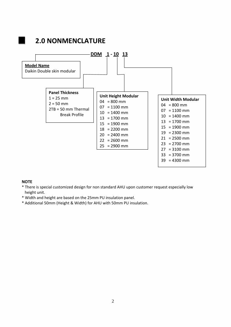
2.0 NONMENCLATURE
DDM 1 - 10 13
NOTE
* There is special customized design for non standard AHU upon customer request especially low
height unit.
* Width and height are based on the 25mm PU insulation panel.
* Additional 50mm (Height & Width) for AHU with 50mm PU insulation.
Model Name
Daikin Double skin modular
Panel Thickness
1 = 25 mm
2 = 50 mm
2TB = 50 mm Thermal
Break Profile
Unit Height Modular
04 = 800 mm
07 = 1100 mm
10 = 1400 mm
13 = 1700 mm
15 = 1900 mm
18 = 2200 mm
20 = 2400 mm
22 = 2600 mm
25 = 2900 mm
Unit Width Modular
04 = 800 mm
07 = 1100 mm
10 = 1400 mm
13 = 1700 mm
15 = 1900 mm
19 = 2300 mm
21 = 2500 mm
23 = 2700 mm
27 = 3100 mm
33 = 3700 mm
39 = 4300 mm
3
3.0 AHU DESIGN FEATURES
3.1 DAIKIN DDM STANDARD FEATURES
• Variable dimensioning features for flexible cabinet sizing (increment 100mm in height and width)
• External Galvanized and internal painted cabinet
• Multiple section depth
• Variable coil casing and drain pan material
• Mixing boxes
• Low leakage damper
• Face and by pass dampers
• Double sloped drain pan
• Different filter grade
• Variable fan selection include forward-curved, backward curved and airfoil
• Variable frequency drive / Frequency inverter (VFD) and thermistor
• Electric heater
• Sound Attenuator/ silencer
• Energy Recovery Section ( Heat Recovery Wheel and Heat Pipe)
• Accessible and maintenance
• Flexibility section for shipment
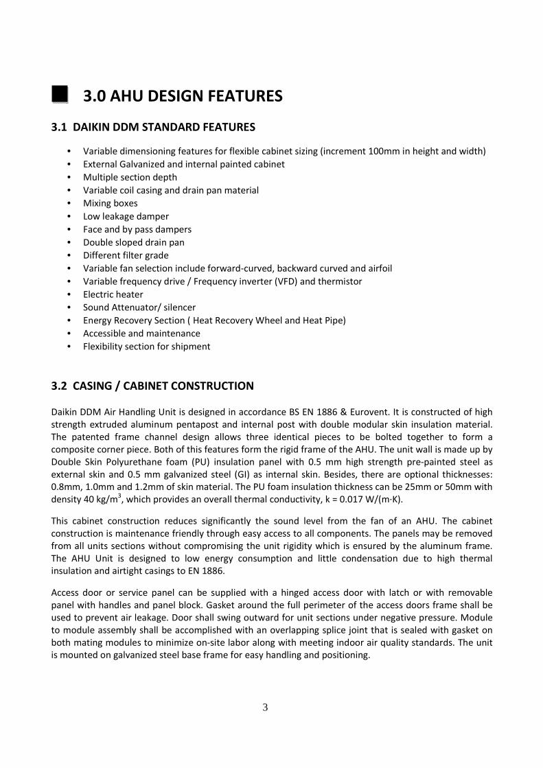
3.2 CASING / CABINET CONSTRUCTION
Daikin DDM Air Handling Unit is designed in accordance BS EN 1886 & Eurovent. It is constructed of high
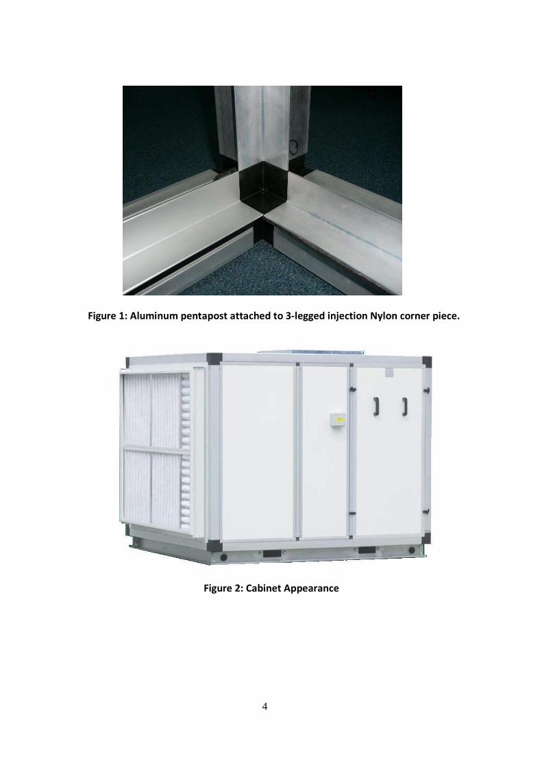
strength extruded aluminum pentapost and internal post with double modular skin insulation material.
The patented frame channel design allows three identical pieces to be bolted together to form a
composite corner piece. Both of this features form the rigid frame of the AHU. The unit wall is made up by
Double Skin Polyurethane foam (PU) insulation panel with 0.5 mm high strength pre-painted steel as
external skin and 0.5 mm galvanized steel (GI) as internal skin. Besides, there are optional thicknesses:
0.8mm, 1.0mm and 1.2mm of skin material. The PU foam insulation thickness can be 25mm or 50mm with
density 40 kg/m3, which provides an overall thermal conductivity, k = 0.017 W/(m·K).
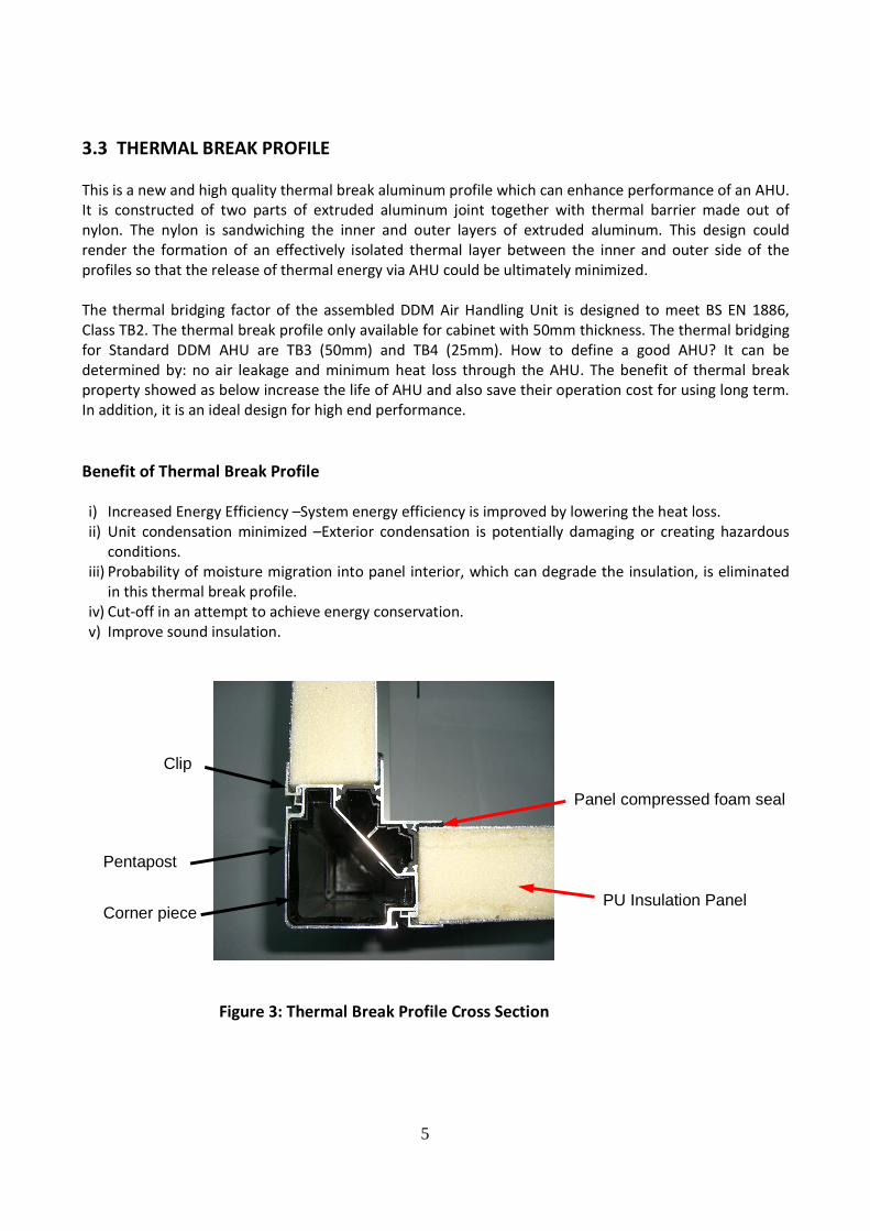
This cabinet construction reduces significantly the sound level from the fan of an AHU. The cabinet
construction is maintenance friendly through easy access to all components. The panels may be removed
from all units sections without compromising the unit rigidity which is ensured by the aluminum frame.
The AHU Unit is designed to low energy consumption and little condensation due to high thermal
insulation and airtight casings to EN 1886.
Access door or service panel can be supplied with a hinged access door with latch or with removable
panel with handles and panel block. Gasket around the full perimeter of the access doors frame shall be
used to prevent air leakage. Door shall swing outward for unit sections under negative pressure. Module
to module assembly shall be accomplished with an overlapping splice joint that is sealed with gasket on
both mating modules to minimize on-site labor along with meeting indoor air quality standards. The unit
is mounted on galvanized steel base frame for easy handling and positioning.
4
Figure 1: Aluminum pentapost attached to 3-legged injection Nylon corner piece.
Figure 2: Cabinet Appearance
5
3.3 THERMAL BREAK PROFILE
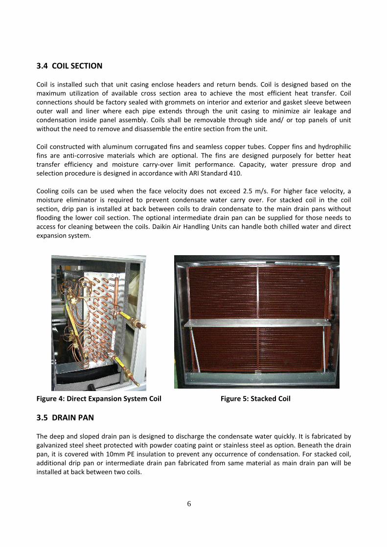
This is a new and high quality thermal break aluminum profile which can enhance performance of an AHU.
It is constructed of two parts of extruded aluminum joint together with thermal barrier made out of
nylon. The nylon is sandwiching the inner and outer layers of extruded aluminum. This design could
render the formation of an effectively isolated thermal layer between the inner and outer side of the
profiles so that the release of thermal energy via AHU could be ultimately minimized.
The thermal bridging factor of the assembled DDM Air Handling Unit is designed to meet BS EN 1886,
Class TB2. The thermal break profile only available for cabinet with 50mm thickness. The thermal bridging
for Standard DDM AHU are TB3 (50mm) and TB4 (25mm). How to define a good AHU? It can be
determined by: no air leakage and minimum heat loss through the AHU. The benefit of thermal break
property showed as below increase the life of AHU and also save their operation cost for using long term.
In addition, it is an ideal design for high end performance.
Benefit of Thermal Break Profile
i) Increased Energy Efficiency –System energy efficiency is improved by lowering the heat loss.
ii) Unit condensation minimized –Exterior condensation is potentially damaging or creating hazardous
conditions.
iii) Probability of moisture migration into panel interior, which can degrade the insulation, is eliminated
in this thermal break profile.
iv) Cut-off in an attempt to achieve energy conservation.
v) Improve sound insulation.
Figure 3: Thermal Break Profile Cross Section
Clip
Corner piece PU Insulation Panel
Panel compressed foam seal
Pentapost
6
3.4 COIL SECTION
Coil is installed such that unit casing enclose headers and return bends. Coil is designed based on the
maximum utilization of available cross section area to achieve the most efficient heat transfer. Coil
connections should be factory sealed with grommets on interior and exterior and gasket sleeve between
outer wall and liner where each pipe extends through the unit casing to minimize air leakage and
condensation inside panel assembly. Coils shall be removable through side and/ or top panels of unit
without the need to remove and disassemble the entire section from the unit.
Coil constructed with aluminum corrugated fins and seamless copper tubes. Copper fins and hydrophilic
fins are anti-corrosive materials which are optional. The fins are designed purposely for better heat
transfer efficiency and moisture carry-over limit performance. Capacity, water pressure drop and
selection procedure is designed in accordance with ARI Standard 410.
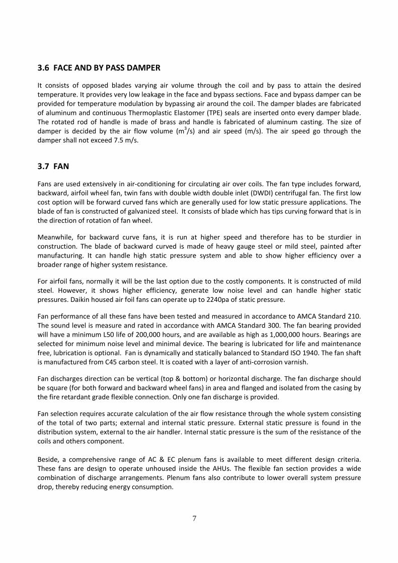
Cooling coils can be used when the face velocity does not exceed 2.5 m/s. For higher face velocity, a
moisture eliminator is required to prevent condensate water carry over. For stacked coil in the coil
section, drip pan is installed at back between coils to drain condensate to the main drain pans without
flooding the lower coil section. The optional intermediate drain pan can be supplied for those needs to
access for cleaning between the coils. Daikin Air Handling Units can handle both chilled water and direct
expansion system.
Figure 4: Direct Expansion System Coil Figure 5: Stacked Coil
3.5 DRAIN PAN
The deep and sloped drain pan is designed to discharge the condensate water quickly. It is fabricated by
galvanized steel sheet protected with powder coating paint or stainless steel as option. Beneath the drain
pan, it is covered with 10mm PE insulation to prevent any occurrence of condensation. For stacked coil,
additional drip pan or intermediate drain pan fabricated from same material as main drain pan will be
installed at back between two coils.
7
3.6 FACE AND BY PASS DAMPER
It consists of opposed blades varying air volume through the coil and by pass to attain the desired
temperature. It provides very low leakage in the face and bypass sections. Face and bypass damper can be
provided for temperature modulation by bypassing air around the coil. The damper blades are fabricated
of aluminum and continuous Thermoplastic Elastomer (TPE) seals are inserted onto every damper blade.
The rotated rod of handle is made of brass and handle is fabricated of aluminum casting. The size of
damper is decided by the air flow volume (m3/s) and air speed (m/s). The air speed go through the
damper shall not exceed 7.5 m/s.
3.7 FAN
Fans are used extensively in air-conditioning for circulating air over coils. The fan type includes forward,
backward, airfoil wheel fan, twin fans with double width double inlet (DWDI) centrifugal fan. The first low
cost option will be forward curved fans which are generally used for low static pressure applications. The
blade of fan is constructed of galvanized steel. It consists of blade which has tips curving forward that is in
the direction of rotation of fan wheel.
Meanwhile, for backward curve fans, it is run at higher speed and therefore has to be sturdier in
construction. The blade of backward curved is made of heavy gauge steel or mild steel, painted after
manufacturing. It can handle high static pressure system and able to show higher efficiency over a
broader range of higher system resistance.
For airfoil fans, normally it will be the last option due to the costly components. It is constructed of mild
steel. However, it shows higher efficiency, generate low noise level and can handle higher static
pressures. Daikin housed air foil fans can operate up to 2240pa of static pressure.
Fan performance of all these fans have been tested and measured in accordance to AMCA Standard 210.
The sound level is measure and rated in accordance with AMCA Standard 300. The fan bearing provided
will have a minimum L50 life of 200,000 hours, and are available as high as 1,000,000 hours. Bearings are
selected for minimum noise level and minimal device. The bearing is lubricated for life and maintenance
free, lubrication is optional. Fan is dynamically and statically balanced to Standard ISO 1940. The fan shaft
is manufactured from C45 carbon steel. It is coated with a layer of anti-corrosion varnish.
Fan discharges direction can be vertical (top & bottom) or horizontal discharge. The fan discharge should
be square (for both forward and backward wheel fans) in area and flanged and isolated from the casing by
the fire retardant grade flexible connection. Only one fan discharge is provided.
Fan selection requires accurate calculation of the air flow resistance through the whole system consisting
of the total of two parts; external and internal static pressure. External static pressure is found in the
distribution system, external to the air handler. Internal static pressure is the sum of the resistance of the
coils and others component.
Beside, a comprehensive range of AC & EC plenum fans is available to meet different design criteria.
These fans are design to operate unhoused inside the AHUs. The flexible fan section provides a wide
combination of discharge arrangements. Plenum fans also contribute to lower overall system pressure
drop, thereby reducing energy consumption.

8
Figure 6: Plenum fan & DWDI centrifugal fan
3.8 MOTOR
Motor is internally mounted integral to an isolated fan assembly. Standard motor shall be horizontal foot
mounting, induction motor, squirrel cage, totally enclosed fan-cooled (TEFC or TEFV) with IP 55 protection
and class F insulation. Motor capacity cannot be undersized but oversized for desired running capacity.
For the desired operation speed between fan and motor, different poles (2, 4, 6 and 8 poles) can be
consider..
MOTOR OPTION
• 380-415 Volt / 3 phase/ 50 Hz ( standard)
• 230/380/440 Volt/ 3 phase/ 60Hz
• Standard efficiency motor (IE1)
• High & Premium efficiency motor (IE2 & IE3)
• Dual speed motor
• Motor with space heater & Thermistor
• Explosion / Flame proof
There are a few components which are able to provide safety,
efficiency and flexibility feature for the operation of AHU. It
includes thermistor, variable frequency drives (VFD),
disconnect switch and others. When operating with VFD,
frequency within 30 to 60 Hz is recommended for standard
induction motor.
Figure 7: Induction Motor

9
3.9 FAN / MOTOR ASSEMBLIES
Fan assemblies are easy to service provided with –
• The adjustable motor bases allow for proper tensioning of
the belts at all times.
• Two-piece split belt guards
• The belt guard is fastened by bolt and nut via three clamps.
Figure 8: Fan / Motor Assemblies
3.10 SPRING ISOLATOR
The fan in AHU can create substantial vibration that will
transform to panels / casing and consequently widespread the
generated sound waves. To avoid this, the spring or rubber
isolator is mounted between the fan compartment and the rest
of the AHU to prevent the transmission of noise and vibration
into panels.
There are two types of isolators used:
• Rubber mounting ( for blower <= model 355)
• 25mm deflection spring ( for blower > model 355)
3.11 THERMISTOR
A thermistor is a type of resistor used to measure temperature changes in protection of windings in
electric motors.
3.12 VFD/ FREQUENCY INVERTER
A VFD provides adjustable speed control of a single fan motor. Normally, an AHU which has been installed
by VFD can vary the frequency within 30 to 60 Hz in order to control the motor rotation speed. It also
provides protection for the motor operation.
3.13 ENERGY RECOVERY
3.13.1 HEAT RECOVERY WHEEL
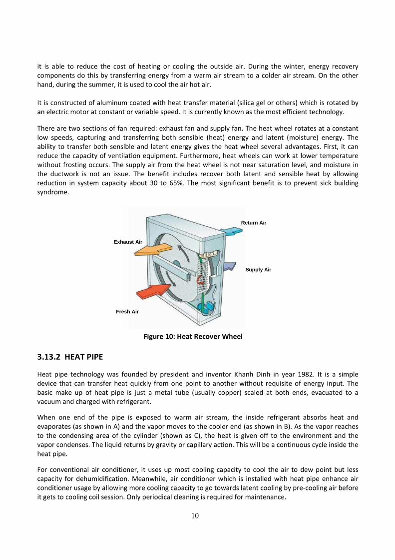
Introducing ventilation from outdoors is essential in maintaining desired indoor air quality. Heat wheel is
available as the option to match this requirement. These energy components can recover 50% or more of
the energy normally exhausted from a building. They are working based on this concept – capture heat
from exhaust air as it passes through the air handling unit and transfer it to the supply air stream. Hence,
Figure 9. Spring Isolator
10
Exhaust Air
Fresh Air
Return Air
Supply Air
it is able to reduce the cost of heating or cooling the outside air. During the winter, energy recovery
components do this by transferring energy from a warm air stream to a colder air stream. On the other
hand, during the summer, it is used to cool the air hot air.
It is constructed of aluminum coated with heat transfer material (silica gel or others) which is rotated by
an electric motor at constant or variable speed. It is currently known as the most efficient technology.
There are two sections of fan required: exhaust fan and supply fan. The heat wheel rotates at a constant
low speeds, capturing and transferring both sensible (heat) energy and latent (moisture) energy. The
ability to transfer both sensible and latent energy gives the heat wheel several advantages. First, it can
reduce the capacity of ventilation equipment. Furthermore, heat wheels can work at lower temperature
without frosting occurs. The supply air from the heat wheel is not near saturation level, and moisture in
the ductwork is not an issue. The benefit includes recover both latent and sensible heat by allowing
reduction in system capacity about 30 to 65%. The most significant benefit is to prevent sick building
syndrome.
3.13.2 HEAT PIPE
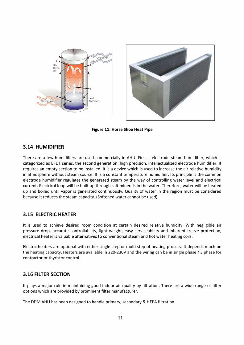
Heat pipe technology was founded by president and inventor Khanh Dinh in year 1982. It is a simple
device that can transfer heat quickly from one point to another without requisite of energy input. The
basic make up of heat pipe is just a metal tube (usually copper) scaled at both ends, evacuated to a
vacuum and charged with refrigerant.
When one end of the pipe is exposed to warm air stream, the inside refrigerant absorbs heat and
evaporates (as shown in A) and the vapor moves to the cooler end (as shown in B). As the vapor reaches
to the condensing area of the cylinder (shown as C), the heat is given off to the environment and the
vapor condenses. The liquid returns by gravity or capillary action. This will be a continuous cycle inside the
heat pipe.
For conventional air conditioner, it uses up most cooling capacity to cool the air to dew point but less
capacity for dehumidification. Meanwhile, air conditioner which is installed with heat pipe enhance air
conditioner usage by allowing more cooling capacity to go towards latent cooling by pre-cooling air before
it gets to cooling coil session. Only periodical cleaning is required for maintenance.
Figure 10: Heat Recover Wheel
11
Figure 11: Horse Shoe Heat Pipe
3.14 HUMIDIFIER
There are a few humidifiers are used commercially in AHU. First is electrode steam humidifier, which is
categorized as BFDT series, the second generation, high precision, intellectualized electrode humidifier. It
requires an empty section to be installed. It is a device which is used to increase the air relative humidity
in atmosphere without steam source. It is a constant temperature humidifier. Its principle is the common
electrode humidifier regulates the generated steam by the way of controlling water level and electrical
current. Electrical loop will be built up through salt minerals in the water. Therefore, water will be heated
up and boiled until vapor is generated continuously. Quality of water in the region must be considered
because it reduces the steam capacity. (Softened water cannot be used).
3.15 ELECTRIC HEATER
It is used to achieve desired room condition at certain desired relative humidity. With negligible air
pressure drop, accurate controllability, light weight, easy serviceability and inherent freeze protection,
electrical heater is valuable alternatives to conventional steam and hot water heating coils.
Electric heaters are optional with either single step or multi step of heating process. It depends much on
the heating capacity. Heaters are available in 220-230V and the wiring can be in single phase / 3 phase for
contractor or thyristor control.
3.16 FILTER SECTION
It plays a major role in maintaining good indoor air quality by filtration. There are a wide range of filter
options which are provided by prominent filter manufacturer.
The DDM AHU has been designed to handle primary, secondary & HEPA filtration.

12
Beside, activated carbon filters are available with designed to improve indoor air quality through the
effective removal of indoor and outdoor gaseous contaminants typically found in the urban environment.
This includes VOCs, SOx, NOx, and Ozone.
3.17 Quick Air Filter Selection Guide
Classification as per EN 779
EN 779 Class G1 G2 G3 G4
Average Arrestance, Am% Am < 65 65 ≤ Am ≤ 80 80 ≤ Am ≤ 90 90 ≤ Am
Recommended Filter - AmerTex R15 AmerTex R29
Aluminum Mesh
AmAir 300E
AmerTex R50
Table 1: Filter Arrestance for Coarse filters in Class G1-G4
EN 779 Class F5 F6 F7 F8 F9
Average Efficiency, Em% 40 ≤ Em ≤ 60 60 ≤ Em ≤ 80 80 ≤ Em ≤ 90 90 ≤ Em ≤ 95 95 ≤ Em
Recommended Filter AmAir 500E DriPak® 2000
DriPak® 2000
Varicel® II
DriPak® 2000
Varicel® II
DriPak® 2000
Varicel VXL
Table 2: Filter Arrestance for fine filters in Class F5-F9
Classification as per EN 1822
EN 1822 Class H 10 H 11 H 12 H 13 H 14
Efficiency (% at 0.3m > 95 > 98 > 99.99 > 99.997 > 99.999
Efficiency (% at MPPS > 85 > 95 > 99.5 > 99.95 > 99.995
Recommended Filter BioCel® I - AstroCel
® I AstroCel
® I AstroCel
® I
Table 3: Filter Efficiency for HEPA Filters Class H10-H14
In addition, filter section can be enhanced by an optional item – filter pressure gauge to ensure regular
filter servicing and prevent clogging. Normally, the filter life span can be indicated by pressure gauge
value for dirty filter should not exceed 300 Pa.

13
Figure 17. A Typical Cut Away View of sound attenuator
3.18 MIXING BOX / DAMPER
It is an air inlet section to mix fresh and return air according to the system designer’s requirement. It can
regulate the amount of outside and return air supplied to the conditioned space. It consists of damper in
parallel blades with opposed rotating blade with driving shaft. The damper blades are fabricated of
aluminum and continuous Thermoplastic Elastomer (TPE) seals are inserted onto every damper blade. The
rotated rod of handle is made of brass and handle is fabricated of aluminum casting. There are a few type
of arrangement: top, rear and combination of top and rear. The mixing box can make use of free cooling
by opening outside air dampers when the ambient air will help to condition the supply air stream. In
addition, dampers maybe individually sized to provide better mixing effect.
3.19 SOUND ATTENUATOR
It has a perimeter galvanized steel frame. Standard pods
is supplied 100mm thick in standard lengths of 900 and
1200mm according to the attenuation required. The
modular widths available are 275mm or 300mm.
Nowadays, sound level will be an essential factor to be
considered as one of the performance of units. Daikin
product has been designing to provide the quietest
sound level. Different attenuator length can be selected
to meet the most stringent sound attenuation
requirements. A comfortable surrounding enhances
human’s working and living life.
Figure 16. Damper & Mixing Box

14
4.0 STANDARD UNITS QUICK SELECTION TABLE
Table 4: Return Air
UNIT Air
Flow ESP
4-ROWS COOLING COIL 1-ROW HEATING COIL MOTOR
SIZE S.C T.C.C Water flow WPD Circuit
T,C Water flow WPD kW
LPS Pa kW kW lps kPa kW lps kPa
0404 646 300 7.3 7.7 0.37 0.27 F 4.7 0.11 0.04 0.75
0407 1027 300 12.6 15.0 0.71 1.16 F 8.8 0.21 0.19 1.1
0410 1408 300 18 22.7 1.08 3.04 F 13.1 0.32 0.48 1.5
0413 1789 300 22.7 30.8 1.47 6.25 F 17.3 0.42 0.95 2.2
0707 1670 300 20.4 24.4 1.16 1.16 F 14.3 0.35 0.19 2.2
0710 2289 300 32.1 42.9 2.04 4.82 F 24.8 0.6 0.76 2.2
0713 2908 300 38.4 50 2.38 6.26 F 28.1 0.69 0.95 3
0715 3321 300 44.5 26 2.79 9.21 F 32.8 0.8 1.39 3.7
1010 3169 350 41.9 54.5 2.60 6.98 M 29.5 0.72 0.48 4
1013 4026 350 54.7 72.9 3.47 14.01 M 39.0 0.95 0.95 5.5
1015 4598 350 68.4 96.0 4.57 30.53 M 52.2 1.27 2.16 4
1019 5741 350 80.0 109.3 5.21 38.05 M 58.8 1.43 0.65 7.5
1021 6312 350 88.7 122.1 5.82 50.05 M 65.8 1.60 3.50 7.5
1315 5619 350 75.3 99.2 4.72 9.2 F 55.4 1.35 1.39 7.5
1319 7016 350 95.3 127.1 6.05 17.09 F 71.8 1.75 2.64 7.5
1321 7715 350 106.1 143.3 6.83 22.83 F 81.4 1.96 3.50 11
1519 7654 450 103.9 138.6 6.60 17.09 F 78.3 1.91 2.65 11
1521 8416 450 115.8 156.3 7.45 22.83 F 87.7 2.14 3.50 11
1819 9568 500 129.9 178.8 8.26 17.09 F 97.9 2.39 2.65 15
1821 10520 500 144.7 195.4 9.31 22.83 F 109.6 2.67 3.50 15
1823 11473 500 167.1 232.5 11.07 38.25 F 130.2 3.17 5.88 15
1827 13378 500 187.2 256.7 12.23 45.29 F 141.9 3.46 6.81 18.5
2027 14270 750 188.6 245.3 11.69 5.69 D 151.4 3.69 6.8 22
2033 17300 750 246.1 335.7 16.50 15.90 D 187.2 5.10 18.5 30
2233 19482 750 262.1 356.9 16.52 10.08 D 210.3 5.12 11.71 37
2239 22900 750 395.0 490.0 23.30 25.60 D 252.2 6.85 28.60 55
2539 24800 750 530.6 389.1 25.27 25.61 D 273.3 7.42 28.57 55
For Cooling Coil: EDB = 27deg. C, EWB = 19.5 deg. C, EWT = 7 deg. C, LWT = 12deg. C
For Heating Coil: EDB =21 deg. C, EWT = 60 deg. C, LWT = 50 deg. C
15
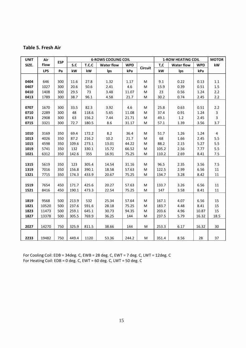
Table 5. Fresh Air
UNIT Air
Flow ESP
6-ROWS COOLING COIL 1-ROW HEATING COIL MOTOR
SIZE. S.C T.C.C Water flow WPD Circuit
T,C Water flow WPD kW
LPS Pa kW kW lps kPa kW lps kPa
0404 646 300 11.6 27.8 1.32 1.17 M 9.1 0.22 0.13 1.1
0407 1027 300 20.6 50.6 2.41 4.6 M 15.9 0.39 0.51 1.5
0410 1408 300 29.5 73 3.48 11.07 M 23 0.56 1.24 2.2
0413 1789 300 38.7 96.1 4.58 21.7 M 30.2 0.74 2.45 2.2
0707 1670 300 33.5 82.3 3.92 4.6 M 25.8 0.63 0.51 2.2
0710 2289 300 48 118.6 5.65 11.08 M 37.4 0.91 1.24 3
0713 2908 300 63 156.2 7.44 21.71 M 49.1 1.2 2.45 3
0715 3321 300 72.7 180.5 8.6 31.17 M 57.1 1.39 3.56 3.7
1010 3169 350 69.4 172.2 8.2 36.4 M 51.7 1.26 1.24 4
1013 4026 350 87.2 216.2 10.2 21.7 M 68 1.66 2.45 5.5
1015 4598 350 109.6 273.1 13.01 44.22 M 88.2 2.15 5.27 5.5
1019 5741 350 132 330.1 15.72 66.52 M 105.2 2.56 7.77 5.5
1021 6312 350 142.6 355 16.91 75.25 M 110.2 2.69 8.41 7.5
1315 5619 350 123 305.4 14.54 31.16 M 96.5 2.35 3.56 7.5
1319 7016 350 156.8 390.1 18.58 57.63 M 122.5 2.99 6.56 11
1321 7715 350 174.3 433.9 20.67 75.25 M 134.7 3.28 8.42 11
1519 7654 450 171.7 425.6 20.27 57.63 M 133.7 3.26 6.56 11
1521 8416 450 190.1 473.3 22.54 75.25 M 147 3.58 8.41 11
1819 9568 500 213.9 532 25.34 57.64 M 167.1 4.07 6.56 15
1821 10520 500 237.6 591.6 28.18 75.25 M 183.7 4.48 8.41 15
1823 11473 500 259.1 645.1 30.73 94.35 M 203.6 4.96 10.87 15
1827 13378 500 305.5 769.9 36.25 144 M 237.5 5.79 16.32 18.5
2027 14270 750 325.9 811.5 38.66 144 M 253.3 6.17 16.32 30
2233 19482 750 449.4 1120 53.36 244.2 M 351.4 8.56 28 37
For Cooling Coil: EDB = 34deg. C, EWB = 28 deg. C, EWT = 7 deg. C, LWT = 12deg. C
For Heating Coil: EDB = 0 deg. C, EWT = 60 deg. C, LWT = 50 deg. C
16
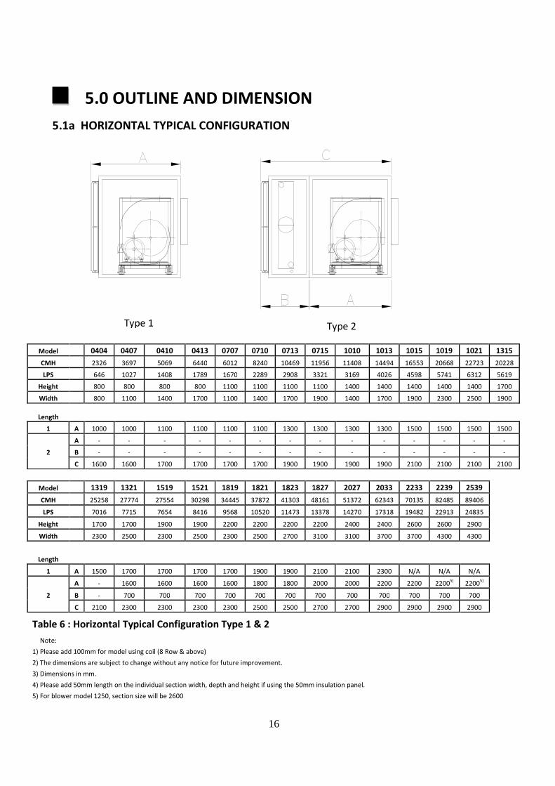
5.0 OUTLINE AND DIMENSION
5.1a HORIZONTAL TYPICAL CONFIGURATION
Model 0404 0407 0410 0413 0707 0710 0713 0715 1010 1013 1015 1019 1021 1315
CMH 2326 3697 5069 6440 6012 8240 10469 11956 11408 14494 16553 20668 22723 20228
LPS 646 1027 1408 1789 1670 2289 2908 3321 3169 4026 4598 5741 6312 5619
Height 800 800 800 800 1100 1100 1100 1100 1400 1400 1400 1400 1400 1700
Width 800 1100 1400 1700 1100 1400 1700 1900 1400 1700 1900 2300 2500 1900
Length
1 A 1000 1000 1100 1100 1100 1100 1300 1300 1300 1300 1500 1500 1500 1500
A - - - - - - - - - - - - - -
2 B - - - - - - - - - - - - - -
C 1600 1600 1700 1700 1700 1700 1900 1900 1900 1900 2100 2100 2100 2100
Model 1319 1321 1519 1521 1819 1821 1823 1827 2027 2033 2233 2239 2539
CMH 25258 27774 27554 30298 34445 37872 41303 48161 51372 62343 70135 82485 89406
LPS 7016 7715 7654 8416 9568 10520 11473 13378 14270 17318 19482 22913 24835
Height 1700 1700 1900 1900 2200 2200 2200 2200 2400 2400 2600 2600 2900
Width 2300 2500 2300 2500 2300 2500 2700 3100 3100 3700 3700 4300 4300
Length
1 A 1500 1700 1700 1700 1700 1900 1900 2100 2100 2300 N/A N/A N/A
A - 1600 1600 1600 1600 1800 1800 2000 2000 2200 2200 22005)
22005)
2 B - 700 700 700 700 700 700 700 700 700 700 700 700
C 2100 2300 2300 2300 2300 2500 2500 2700 2700 2900 2900 2900 2900
Table 6 : Horizontal Typical Configuration Type 1 & 2
Note:
1) Please add 100mm for model using coil (8 Row & above)
2) The dimensions are subject to change without any notice for future improvement.
3) Dimensions in mm.
4) Please add 50mm length on the individual section width, depth and height if using the 50mm insulation panel.
5) For blower model 1250, section size will be 2600
Type 1 Type 2

17
5.1b HORIZONTAL TYPICAL CONFIGURATION
Model 0404 0407 0410 0413 0707 0710 0713 0715 1010 1013 1015 1019 1021 1315
CMH 2326 3697 5069 6440 6012 8240 10469 11956 11408 14494 16553 20668 22723 20228
LPS 646.1 1027 1408 1789 1670 2289 2908 3321 3169 4026 4598 5741 6312 5619
Height 800 800 800 800 1100 1100 1100 1100 1400 1400 1400 1400 1400 1700
Width 800 1100 1400 1700 1100 1400 1700 1900 1400 1700 1900 2300 2500 1900
Length
3
A 900 900 1000 1000 1000 1000 1200 1200 1200 1200 1400 1400 1400 1400
B 1300 1300 1300 1300 1300 1300 1300 1300 1300 1300 1300 1300 1300 1300
C 2200 2200 2300 2300 2300 2300 2500 2500 2500 2500 2700 2700 2700 2700
4
A - - - - - - - - - - - - - -
B - - - - - - - - - - - - - -
C - - - - 500 500 500 500 600 600 600 600 600 600
D - - - - 1700 1700 1900 1900 1900 1900 2100 2100 2100 2100
E 2000 2000 2100 2100 2200 2200 2400 2400 2500 2500 2700 2700 2700 2700
Model 1319 1321 1519 1521 1819 1821 1823 1827 2027 2033 2233 2239 2539
CMH 25258 27774 27554 30298 34445 37872 41303 48161 51372 62343 70135 82485 89406
LPS 7016 7715 7654 8416 9568 10520 11473 13378 14270 17318 19482 22913 24835
Height 1700 1700 1900 1900 2200 2200 2200 2200 2400 2400 2600 2600 2900
Width 2300 2500 2300 2500 2300 2500 2700 3100 3100 3700 3700 4300 4300
Length
3
A 1400 1600 1600 1600 1600 1800 1800 2000 2000 2200 2200 22005)
22005)
B 1300 1300 1300 1300 1300 1300 1300 1300 1300 1300 1300 1300 1300
C 2700 2900 2900 2900 2900 3100 3100 3300 3300 3500 3500 3500 3500
4
A - 1600 1600 1600 1600 1800 1800 2000 2000 2200 2200 22005)
22005)
B - 1300 1400 1400 1400 1500 1500 1500 1500 1700 1700 1900 1900
C 600 - - - - - - - - - - - -
D 2100 - - - - - - - - - - - - E 2700 2900 3000 3000 3000 3300 3300 3500 3500 3900 3900 4100 4100
Table 7 : Horizontal Typical Configuration Type 3 & 4
Note:
1) Please add 100mm for model using coil (8 Row & above)
2) The dimensions are subject to change without any notice for future improvement.
3) Dimensions in mm.
4) Please add 50mm length on the individual section width, depth and height if using the 50mm insulation panel.
5) For blower model 1250, section size will be 2600
Type 3 Type 4

18
5.1c HORIZONTAL TYPICAL CONFIGURATION
Model 0404 0407 0410 0413 0707 0710 0713 0715 1010 1013 1015 1019 1021 1315
CMH 2326 3697 5069 6440 6012 8240 10469 11956 11408 14494 16553 20668 22723 20228
LPS 646 1027 1408 1789 1670 2289 2908 3321 3169 4026 4598 5741 6312 5619
Height 800 800 800 800 1100 1100 1100 1100 1400 1400 1400 1400 1400 1700
Width 800 1100 1400 1700 1100 1400 1700 1900 1400 1700 1900 2300 2500 1900
Length
5
A - - - - - - - - - - - - - -
B - - - - - - - - - - - - - -
C 1100 1100 1100 1100 1200 1200 1200 1200 1300 1300 1300 1300 1300 1300
D 1500 1500 1600 1600 1600 1600 1800 1800 1800 1800 2000 2000 2000 2000
E 2600 2600 2700 2700 2800 2800 3000 3000 3100 3100 3300 3300 3300 3300
6
A - - 1000 1000 1000 1000 1200 1200 1200 1200 1400 1400 1400 1400
B - - 1300 1300 1300 1300 1300 1300 1300 1300 1300 1300 1300 1300
C 2100 2100 2300 2300 2300 2300 2500 2500 2500 2500 2700 2700 2700 2700
Model 1319 1321 1519 1521 1819 1821 1823 1827 2027 2033 2233 2239 2539
CMH 25258 27774 27554 30298 34445 37872 41303 48161 51372 62343 70135 82485 89406
LPS 7016 7715 7654 8416 9568 10520 11473 13378 14270 17318 19482 22913 24835
Height 1700 1700 1900 1900 2200 2200 2200 2200 2400 2400 2600 2600 2900
Width 2300 2500 2300 2500 2300 2500 2700 3100 3100 3700 3700 4300 4300
Length
5
A - 1600 1600 1600 1600 1800 1800 2000 2000 2200 2200 22005)
22005)
B - 600 600 600 600 600 600 600 600 600 600 600 600
C 1300 1300 1400 1400 1400 1500 1500 1500 1500 1700 1700 1900 1900
D 2000 - - - - - - - - - E 3300 3500 3600 3600 3600 3900 3900 4100 4100 4500 4500 4700 4700
6
A 1400 1600 1600 1600 1600 1800 1800 2000 2000 2200 2200 22005)
22005)
B 1300 1300 1300 1300 1300 1300 1300 1300 1300 1300 1300 1300 1300
C 2700 2900 2900 2900 2900 3100 3100 3300 3300 3500 3500 3700 3700
Table 8 : Horizontal Typical Configuration Type 5 & 6
Note:
1) Please add 100mm for model using coil (8 Row & above)
2) The dimensions are subject to change without any notice for future improvement.
3) Dimensions in mm.
4) Please add 50mm length on the individual section width, depth and height if using the 50mm insulation panel.
5) For blower model 1250, section size will be 2600

19
5.1d HORIZONTAL TYPICAL CONFIGURATION
Model 404 407 410 413 707 710 713 715 1010 1013 1015 1019 1021 1315
CMH 2326 3697 5069 6440 6012 8240 10469 11956 11408 14494 16553 20668 22723 20228
LPS 646.1 1027 1408 1789 1670 2289 2908 3321 3169 4026 4598 5741 6312 5619
Height 800 800 800 800 1100 1100 1100 1100 1400 1400 1400 1400 1400 1700
Width 800 1100 1400 1700 1100 1400 1700 1900 1400 1700 1900 2300 2500 1900
Length
A - - - - - - 1200 1200 1200 1200 1400 1400 1400 1400
B - - - - - - 1900 1900 1900 1900 1900 1900 1900 1900
7 C 2100 2100 2200 2200 2200 2200 - - - - - - - -
D 700 700 700 700 700 700 - - - - - - - -
E 2800 2800 2900 2900 2900 2900 3100 3100 3100 3100 3300 3300 3300 3300
A - - 1000 1000 1000 1000 1200 1200 1200 1200 1400 1400 1400 1400
B - - 1300 1300 1300 1300 1300 1300 1300 1300 1300 1300 1300 1300
8 C 400 400 400 400 500 500 500 500 600 600 600 600 600 600
D 2200 2200 - - - - - - - - - - - -
E 2600 2600 2700 2700 2800 2800 3000 3000 3100 3100 3300 3300 3300 3300
Model 1319 1321 1519 1521 1819 1821 1823 1827 2027 2033 2233 2239 2539
CMH 25258 27774 27554 30298 34445 37872 41303 48161 51372 62343 70135 82485 89406
LPS 7016 7715 7654 8416 9568 10520 11473 13378 14270 17318 19482 22913 24835
Height 1700 1700 1900 1900 2200 2200 2200 2200 2400 2400 2600 2600 2900
Width 2300 2500 2300 2500 2300 2500 2700 3100 3100 3700 3700 4300 4300
Length
A 1400 1600 1600 1600 1600 1800 1800 2000 2000 2200 2200 22005)
22005)
B 1900 1900 1900 1900 1900 1900 1900 1900 1900 1900 1900 1900 1900
7 C - - - - - - - - - - - - - D - - - - - - - - - - - - - E 3300 3500 3500 3500 3500 3700 3700 3900 3900 4100 4100 4100 4100 A 1400 1600 1600 1600 1600 1800 1800 2000 2000 2200 2200 2200
5) 2200
5)
B 1200 1300 1300 1300 1300 1300 1300 1300 1300 1300 1300 1300 1300 8 C 600 600 700 700 700 800 800 800 800 1000 1000 1200 1200 D - - - - - - - - - - - - - E 3300 3500 3600 3600 3600 3900 3900 4100 4100 4500 4500 4700 4700
Table 9 : Horizontal Typical Configuration Type 7 & 8
Note:
1) Please add 100mm for model using coil (8 Row & above)
2) The dimensions are subject to change without any notice for future improvement.
3) Dimensions in mm.
4) Please add 50mm length on the individual section width, depth and height if using the 50mm insulation panel.
5) For blower model 1250, section size will be 2600
Type 7 Type 8

20
5.1e HORIZONTAL TYPICAL CONFIGURATION
Model 0404 0407 0410 0413 0707 0710 0713 0715 1010 1013 1015 1019 1021 1315
CMH 2326 3697 5069 6440 6012 8240 10469 11956 11408 14494 16553 20668 22723 20228
LPS 646.1 1027 1408 1789 1670 2289 2908 3321 3169 4026 4598 5741 6312 5619
Height 800 800 800 800 1100 1100 1100 1100 1400 1400 1400 1400 1400 1700
Width 800 1100 1400 1700 1100 1400 1700 1900 1400 1700 1900 2300 2500 1900
Length
A - - - - - - 1200 1200 1200 1200 1400 1400 1400 1400
B - - - - - - 1200 1200 1200 1200 1200 1200 1200 1200
9 C 1100 1100 1100 1100 1200 1200 1200 1200 1300 1300 1300 1300 1300 1300
D 2100 2100 2200 2200 2200 2200 - - - - - - - -
E 3200 3200 3300 3300 3400 3400 3600 3600 3700 3700 3900 3900 3900 3900
Model 1319 1321 1519 1521 1819 1821 1823 1827 2027 2033 2233 2239 2539
CMH 25258 27774 27554 30298 34445 37872 41303 48161 51372 62343 70135 82485 89406
LPS 7016 7715 7654 8416 9568 10520 11473 13378 14270 17318 19482 22913 24835
Height 1700 1700 1900 1900 2200 2200 2200 2200 2400 2400 2600 2600 2900
Width 2300 2500 2300 2500 2300 2500 2700 3100 3100 3700 3700 4300 4300
Length
A 1400 1600 1600 1600 1600 1800 1800 2000 2000 2200 2200 22005)
22005)
B 1200 1200 1200 1200 1200 1200 1200 1200 1200 1200 1200 1200 1200
9 C 1300 1300 1400 1400 1400 1500 1500 1500 1500 1700 1700 1900 1900
D - - - - - - - - - - - - -
E 3900 4100 4200 4200 4200 4500 4500 4700 4700 5100 5100 5300 5300
Table 10 : Horizontal Typical Configuration Type 9
Note:
1) Please add 100mm for model using coil (8 Row & above)
2) The dimensions are subject to change without any notice for future improvement.
3) Dimensions in mm.
4) Please add 50mm length on the individual section width, depth and height if using the 50mm insulation panel.
5) For blower model 1250, section size will be 2600
Type 9
21
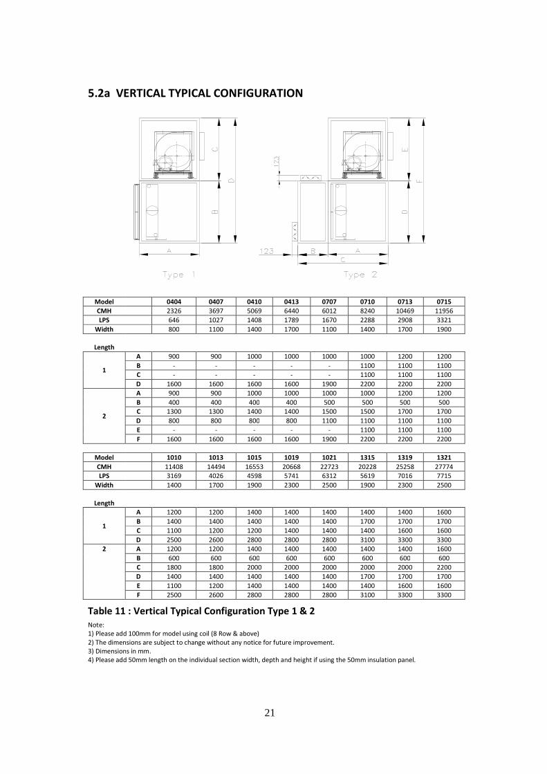
5.2a VERTICAL TYPICAL CONFIGURATION
Model 0404 0407 0410 0413 0707 0710 0713 0715
CMH 2326 3697 5069 6440 6012 8240 10469 11956
LPS 646 1027 1408 1789 1670 2288 2908 3321
Width 800 1100 1400 1700 1100 1400 1700 1900
Length
1
A 900 900 1000 1000 1000 1000 1200 1200
B - - - - - 1100 1100 1100
C - - - - - 1100 1100 1100
D 1600 1600 1600 1600 1900 2200 2200 2200
2
A 900 900 1000 1000 1000 1000 1200 1200
B 400 400 400 400 500 500 500 500
C 1300 1300 1400 1400 1500 1500 1700 1700
D 800 800 800 800 1100 1100 1100 1100
E - - - - - 1100 1100 1100
F 1600 1600 1600 1600 1900 2200 2200 2200
Model 1010 1013 1015 1019 1021 1315 1319 1321
CMH 11408 14494 16553 20668 22723 20228 25258 27774
LPS 3169 4026 4598 5741 6312 5619 7016 7715
Width 1400 1700 1900 2300 2500 1900 2300 2500
Length
1
A 1200 1200 1400 1400 1400 1400 1400 1600
B 1400 1400 1400 1400 1400 1700 1700 1700
C 1100 1200 1200 1400 1400 1400 1600 1600
D 2500 2600 2800 2800 2800 3100 3300 3300
2 A 1200 1200 1400 1400 1400 1400 1400 1600
B 600 600 600 600 600 600 600 600
C 1800 1800 2000 2000 2000 2000 2000 2200
D 1400 1400 1400 1400 1400 1700 1700 1700
E 1100 1200 1400 1400 1400 1400 1600 1600
F 2500 2600 2800 2800 2800 3100 3300 3300
Table 11 : Vertical Typical Configuration Type 1 & 2
Note:
1) Please add 100mm for model using coil (8 Row & above)
2) The dimensions are subject to change without any notice for future improvement.
3) Dimensions in mm.
4) Please add 50mm length on the individual section width, depth and height if using the 50mm insulation panel.
22
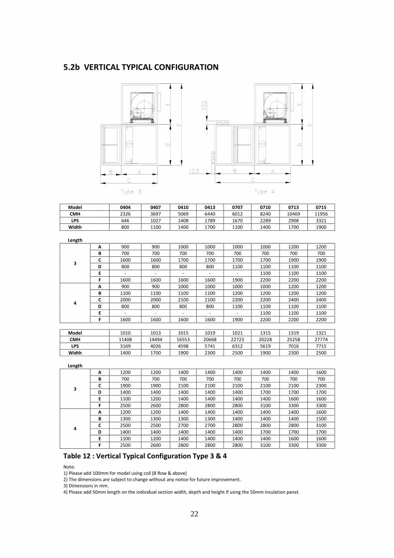
5.2b VERTICAL TYPICAL CONFIGURATION
Model 0404 0407 0410 0413 0707 0710 0713 0715
CMH 2326 3697 5069 6440 6012 8240 10469 11956
LPS 646 1027 1408 1789 1670 2289 2908 3321
Width 800 1100 1400 1700 1100 1400 1700 1900
Length
3
A 900 900 1000 1000 1000 1000 1200 1200
B 700 700 700 700 700 700 700 700
C 1600 1600 1700 1700 1700 1700 1900 1900
D 800 800 800 800 1100 1100 1100 1100
E - - - - - 1100 1100 1100
F 1600 1600 1600 1600 1900 2200 2200 2200
4
A 900 900 1000 1000 1000 1000 1200 1200
B 1100 1100 1100 1100 1200 1200 1200 1200
C 2000 2000 2100 2100 2200 2200 2400 2400
D 800 800 800 800 1100 1100 1100 1100
E - - - - - 1100 1100 1100
F 1600 1600 1600 1600 1900 2200 2200 2200
Model 1010 1013 1015 1019 1021 1315 1319 1321
CMH 11408 14494 16553 20668 22723 20228 25258 27774
LPS 3169 4026 4598 5741 6312 5619 7016 7715
Width 1400 1700 1900 2300 2500 1900 2300 2500
Length
3
A 1200 1200 1400 1400 1400 1400 1400 1600
B 700 700 700 700 700 700 700 700
C 1900 1900 2100 2100 2100 2100 2100 2300
D 1400 1400 1400 1400 1400 1700 1700 1700
E 1100 1200 1400 1400 1400 1400 1600 1600
F 2500 2600 2800 2800 2800 3100 3300 3300
4
A 1200 1200 1400 1400 1400 1400 1400 1600
B 1300 1300 1300 1300 1400 1400 1400 1500
C 2500 2500 2700 2700 2800 2800 2800 3100
D 1400 1400 1400 1400 1400 1700 1700 1700
E 1100 1200 1400 1400 1400 1400 1600 1600
F 2500 2600 2800 2800 2800 3100 3300 3300
Table 12 : Vertical Typical Configuration Type 3 & 4
Note:
1) Please add 100mm for model using coil (8 Row & above)
2) The dimensions are subject to change without any notice for future improvement.
3) Dimensions in mm.
4) Please add 50mm length on the individual section width, depth and height if using the 50mm insulation panel.

23
Figure 18: Discharge duct layout
Notes: 1.Elbows should not be closer than 1 1/2 to 21/2 times the largest dimension of fan discharge opening.
2. Dampers should be placed at least fan diameters downstream of the fan discharge.
FIGURES REPRINTED WITH PERMISSION FROM THE 1979 ASHRAE GUIDE AND DATA BOOK (EQUIPMENT).
6.0 APPLICATION CONSIDERATIONS
6.1 Installation Flexibility
Daikin AHU feature sectionalized design to provide maximum installation flexibility. Mixing box, filter, coil,
fan and access components permit the design flexibility of built-up systems with the cost-effective of
factory fabricated units. Every section is fabricated of heavy-gauge continuous galvanized steel or
extruded aluminum with exacting assembly procedures and rigid quality control standards.
6.2 Mounting and Access
Whether units are floor or ceiling mounted, care should be taken to ensure that the supporting structure
is level and rigid enough for satisfactory unit operation. Ideally, a heavy concrete slab should be used for
bottom mounted units, and main support beams for top hung units. Long floor or ceiling spans should be
avoided.
Unit should be located so as to provide proper access for routine service. Clearance for filter removal on
both sides of the filter section is usually necessary. Clearance should be provided as required for access
panels. Room should be allowed for coil removal. Cooling units require clearance for a trap in the drain
pan line.
Access to the interior of Daikin air handlers is provided by hinged access doors or removable panels
wherever possible. For access between components, a versatile access section features hinged access
doors at both ends.
6.3 Ductwork
Good ductwork layout will minimize system resistance and sound generation. Duct connections to and
from units should allow straight, smooth airflow. Sharp turns in the fan discharge should be avoided,
particularly turns opposed to wheel rotation. Turning vanes should be used. Discharge plenums or any
abrupt change in duct should be avoided.

24
Figure 19: Drain pan traps
6.4 Piping and Drain Fan Traps
Piping should be in accordance with accepted industry
standards. Undue stress should not be applied at the
connection to coil headers. Pipe work should be
supported independently of the coils with adequate
piping flexibility for thermal expansion. Drain lines and
traps should be run full size from the drain pan
connection. Drain pans should have traps to permit the
condensate from the coils to drain freely. On a draw-
through unit, the trap depth and the distance between
the trap outlet and the drain pan outlet should be twice
the negative static pressure under normal unit operation.
6.5 Air Supply Systems and Fan Laws
An air supply system consists of an AHU cabinet, heat exchanger, filters, ductwork, grilles and register
used to distribute air throughout the building. The system is independent of the fan used to supply the
system. The resistance of the system, referred to as static pressure (SP), is dependent upon the quantity
of air (CFM) that is moved through it. The air quantity is determined by the cooling, heating and
ventilating requirements.
For any system, the static pressure will vary directly as the square of the air quantity. This relationship
between CFM and SP establishes the system curve for that system and may be expressed as follows:
2
1
212
2
1
2
2
1
==
CFM
CFMSPSPor
SP
SP
CFM
CFM
The system curve is unique for a particular system configuration. Any change to the system caused by
dirty filters, damper change, etc., will result in new system curve.
For fans operating at low pressures (less than 10” W.G.), the effects of air compression allows fan
operation in a fixed system to be expressed by simple relationships. These relationships are known as fan
laws and may be used to calculate the effects of fan speed and air density changes on this system.
1. The flow rate varies directly with the change in fan speed:
==
1
212
2
1
2
1
RPM
RPMCFMCFMor
RPM
RPM
CFM
CFM
A 10% increase in fan speed will give a 10% increase in air quantity.

25
2. The static pressure varies as the square of the change in fan speed: 2
1
212
2
2
1
2
1
=
=
RPM
RPMSPSPor
RPM
RPM
SP
SP
A 10% increase in fan speed will give a 21% increase in air static pressure.
3. The fan brake horsepower varies as the cube of the change in fan speed:
A 10% increase in fan speed will give a 33% increase in fan horsepower.
4. System static pressure and brake horsepower are directly proportional to the air density:
2
1
2
1
212
=
RPM
RPM
Density
DensitySPSP
3
1
2
1
212
=
RPM
RPM
Density
DensityHPHP
Consequently, the static pressure and brake horsepower decrease with an increase in air temperature or
higher altitude, and increase with a decrease in air temperature or lower altitude.
To determine fan performance for temperatures and altitudes other than standard (70oF, 0 ft. altitude),
the static pressure must be adjusted by the density ratio before the fan RPM and BHP requirement can be
determined. Density ratios are expressed as temperature and altitude conversion factors in Table 13.
AIR ALTITUDE (FEET
TEMP 0 1000 2000 3000 4000 5000 6000 7000 8000
(oF
-20 1.20 1.16 1.12 1.08 1.04 1.00 0.97 0.93 0.89
0 1.15 1.10 1.08 1.02 0.99 0.95 0.92 0.88 0.85
20 1.11 1.06 1.02 0.98 0.95 0.92 0.88 0.85 0.82
40 1.06 1.02 0.98 0.94 0.91 0.88 0.84 0.81 0.78
60 1.02 0.98 0.94 0.91 0.88 0.85 0.81 0.79 0.76
70 1.00 0.96 0.93 0.89 0.86 0.83 0.80 0.77 0.74
80 0.98 0.94 0.91 0.88 0.84 0.81 0.78 0.75 0.72
100 0.94 0.91 0.88 0.84 0.81 0.78 0.75 0.72 0.70
120 0.92 0.88 0.85 0.81 0.78 0.76 0.72 0.70 0.67
140 0.89 0.85 0.82 0.79 0.76 0.73 0.70 0.68 0.65
160 0.85 0.82 0.79 0.76 0.74 0.70 0.68 0.65 0.63
200 0.80 0.77 0.75 0.72 0.69 0.67 0.64 0.62 0.60
250 0.75 0.72 0.69 0.67 0.65 0.62 0.60 0.58 0.56
Table 13: Temperature and altitude conversion
3
1
212
3
2
1
2
1
=
=
RPM
RPMHPHP
RPM
RPM
HP
HP

26
7.0 FAN SPECIFICATION
Fan Section Arrangement Units
Model Available Discharge Maximum Motor R/RI/T/TI Discharge
Fan Size Size Motor Size Mounting Depth (mm)
(mm) (kW) Position
180 230x230 3 Rear 900
0404 200 260x260 3 Rear 900 225 295x295 4 Rear 900
0407 225 295x295 4 Rear 900 250 330x330 4 Side 900 250 330x330 7.5 Side 1000
0410 280 370x370 7.5 Side 1000 315 410x410 7.5 Side 1000
0413 315 410x410 7.5 Side 1000 355 460x460 7.5 Side 1000
0707 280 370x370 4 Side 1000 315 410x410 2.2 Side 1000
0710 315 410x410 7.5 Side 1000 355 460x460 7.5 Side 1000
0713 400 515x515 15 Side 1200
450 575x575 11 Side 1200 0715 400 515x515 18.5 Side 1200
450 575x575 18.5 Side 1200 1010 355 460x460 7.5 Side 1200
400 515x515 7.5 Side 1200 1013 450 575x575 11 Side 1200
500 645x645 7.5 Side 1200 1015 450 575x575 18.5 Side 1400
500 645x645 30 Side 1400
500 645x645 55 Side 1400
1019 560 720x720 55 Side 1400
630 810x810 45 Side 1400 1021 560 720x720 55 Side 1400
630 810x810 55 Side 1400 1315 500 645x645 30 Side 1400
560 720x720 11 Side 1400 1319 560 720x720 35 Side 1400
630 810x810 45 Side 1400 560 720x720 55 Side 1600
1321 630 810x810 55 Side 1600 710 910x910 55 Side 1600
1519 560 720x720 55 Side 1600 630 810x810 45 Side 1600
1521 630 810x810 55 Side 1600 710 910x910 55 Side 1600
1819 630 810x810 45 Side 1600 710 910x910 22 Side 1600
1821 710 910x910 55 Side 1800
800 1010x1010 30 Side 1800
1823 710 910x910 55 Side 1800
800 1010x1010 55 Side 1800
800 1010x1010 55 Side 2000
1827 900 1200x1200 55 Side 2000
1000 1300x1300 55 Side 2000

27
Fan Section Arrangement Units
Model Available Discharge Maximum Motor R/RI/T/TI Discharge
Fan Size Motor Mounting Depth
Size Size
mm kW Position mm
800 1010x1010 55 Side 2000
2027 900 1200x1200 55 Side 2000
1000 1300x1300 55 Side 2000
900 1200x1200 55 Side 2200
2033 1000 1300x1300 55 Side 2200
1120 1430x1430 55 Side 2200
900 1200x1200 55 Side 2200
2233 1000 1300x1300 55 Side 2200
1120 1430x1430 55 Side 2200
1000 1300x1300 55 Side 2200
2239 1120 1430x1430 55 Side 2200
1250 1530x1530 55 Side 2600
2539 1120 1430x1430 55 Side 2200
1250 1530x1530 55 Side 2600
Table 14.

28
COIL
COIL
COIL
COIL
Front
Front inverted
Top
Top Inverted
Horizontal Arrangement Unit.
Vertical Arrangement Unit.
COIL
Front Front inverted
Top Top Inverted
COIL
COIL
COIL
COIL
Rear Rear inverterCOIL
7.1 FAN DISCHARGE ARRANGEMENT
Figure 20.
Figure 21.
29
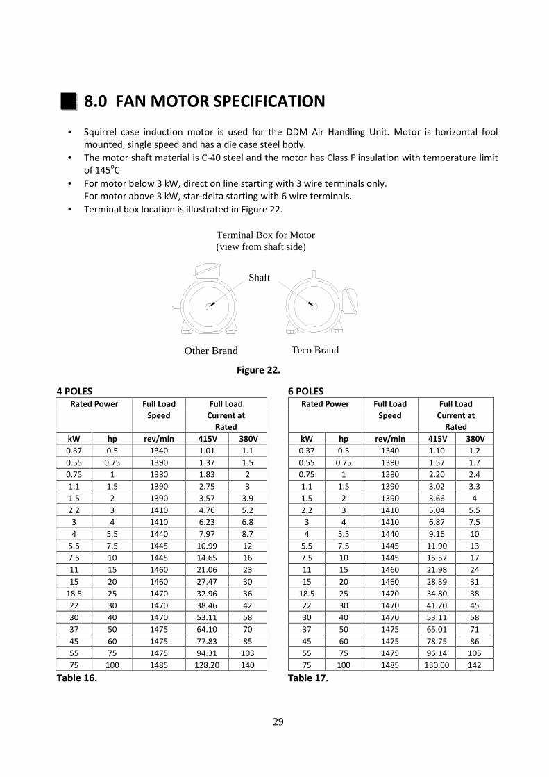
8.0 FAN MOTOR SPECIFICATION
• Squirrel case induction motor is used for the DDM Air Handling Unit. Motor is horizontal fool
mounted, single speed and has a die case steel body.
• The motor shaft material is C-40 steel and the motor has Class F insulation with temperature limit
of 145oC
• For motor below 3 kW, direct on line starting with 3 wire terminals only.
For motor above 3 kW, star-delta starting with 6 wire terminals.
• Terminal box location is illustrated in Figure 22.
4 POLES 6 POLES Rated Power Full Load Full Load Rated Power Full Load Full Load
Speed Current at Speed Current at
Rated Rated
kW hp rev/min 415V 380V kW hp rev/min 415V 380V
0.37 0.5 1340 1.01 1.1 0.37 0.5 1340 1.10 1.2
0.55 0.75 1390 1.37 1.5 0.55 0.75 1390 1.57 1.7
0.75 1 1380 1.83 2 0.75 1 1380 2.20 2.4
1.1 1.5 1390 2.75 3 1.1 1.5 1390 3.02 3.3
1.5 2 1390 3.57 3.9 1.5 2 1390 3.66 4
2.2 3 1410 4.76 5.2 2.2 3 1410 5.04 5.5
3 4 1410 6.23 6.8 3 4 1410 6.87 7.5
4 5.5 1440 7.97 8.7 4 5.5 1440 9.16 10
5.5 7.5 1445 10.99 12 5.5 7.5 1445 11.90 13
7.5 10 1445 14.65 16 7.5 10 1445 15.57 17
11 15 1460 21.06 23 11 15 1460 21.98 24
15 20 1460 27.47 30 15 20 1460 28.39 31
18.5 25 1470 32.96 36 18.5 25 1470 34.80 38
22 30 1470 38.46 42 22 30 1470 41.20 45
30 40 1470 53.11 58 30 40 1470 53.11 58
37 50 1475 64.10 70 37 50 1475 65.01 71
45 60 1475 77.83 85 45 60 1475 78.75 86
55 75 1475 94.31 103 55 75 1475 96.14 105
75 100 1485 128.20 140 75 100 1485 130.00 142
Table 16. Table 17.
Figure 22.
Shaft
OYL Brand Teco Brand
Terminal Box for Motor (view from shaft side)
Other Brand

30
9.0 BELT AND PULLEY SPECIFICATION
• DDM Air Handling Unit comes standard with taper lock pulley and wedge belt with optional
adjustable pulley and belt.
• Standard service factor of 1.5 suitable for 24 hours operation.
9.1 PULLEY ALIGNMENT
• Adjust the motor pulley to align with the fan pulley with the use of a straight edge.
• Do not force belts on the pulleys groove.
• Firstly, loosen the bolts at motor base until belt can slide smoothly over pulleys edge.
• When all the belts are in place, proceed to adjust belt tension using the adjusting nuts on the
motor mount.
• Figure 23 illustrates the pulleys alignment.
Figure 23
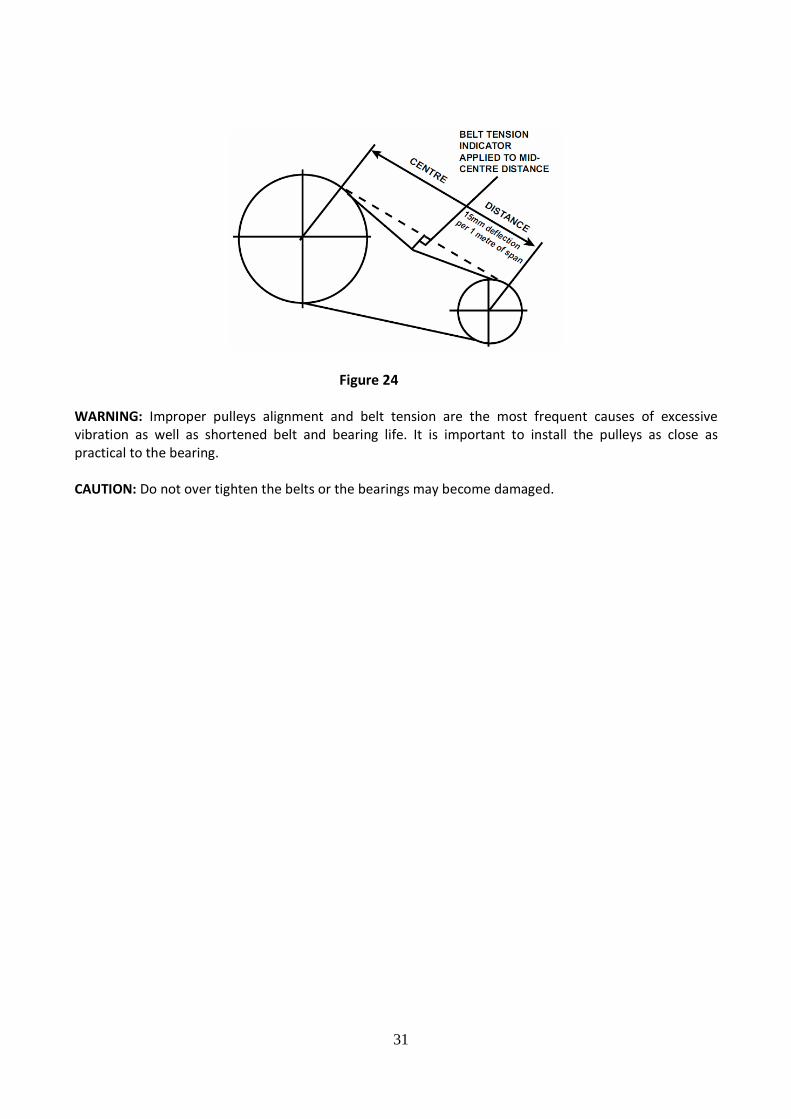
• To check the belt tension, apply a force K large enough at the centre of the belt to deflect the belt
15mm per meter. The deflection force for any belt should be within the minimum and maximum
force shown in Table 18.
• When the tension drops to the minimum value, readjust to the maximum value.
• During normal operation a belt seat itself in pulleys grooves and require periodical checks to
maintain tension.
1
Shafts are
not parallel
to one
another.
2
Shafts are not in
correct alignment
they appear parallel
when seen from
above.
3
Shafts are parallel
and in alignment
but pulleys are
not in alignment
4 Correct installation both shafts and pulleys are parallel and in alignment
31
Figure 24
WARNING: Improper pulleys alignment and belt tension are the most frequent causes of excessive
vibration as well as shortened belt and bearing life. It is important to install the pulleys as close as
practical to the bearing.
CAUTION: Do not over tighten the belts or the bearings may become damaged.

32
10.0 COIL SPECIFICATION
The DDM Air Handling Units can be used for both chilled water system and direct expansion system
application. Coils are designed based on application to best meet the requirements.
• Standard Aluminum fins are maximum 12 FPI (fin per inch). Copper fins are also available as
option. Fin thickness is 0.115mm and fin hardness is H0 and H22 for standard aluminum fin and
others fins respectively. Fins can be coated by Heresite or Hydrophilic fin material as a corrosion
protective layer.
• Standard coil frame is in 1.5mm thick galvanized steel (GI) while stainless steel (SSTL) is available
as an option when copper fin is used to avoid galvanization effect. Coil casing is designed to have
drain holes at the bottom channels to ensure condensate drainage.
• For water system, the coil is available in 1, 2, 3, 4, 5, 6, 8, 10 and 12 rows. Header and collar is
constructed of steel with copper material as the option. Its size is either 42 or 76 mm. Piping
connection is only one sided, either “left” or “right”, viewing from return air side. The connection
for steel header is by Male Pitch Threaded (MPT) joint. Copper header connection will be brazed
joint type and optional for Male Pitch Threaded (MPT).
• For a direct expansion system, the coil is available in 2, 3, 4, 5, 6 and 8 rows. TXV valve is optional
item. Header is only available in copper materials. Pipe connection is by brazing joint.
• The standard working pressure of the coil is 250 psig (17 bar). During fabrication, coil leak test are
perform at pressure of 350 psig (24 bar).
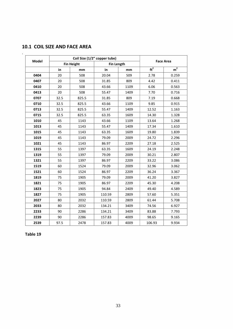
• Coil surface area is standard size for each model and it is common for chilled water and direct
expansion coil type. (Please refer Table 19.)
Figure 25
TOP VIEWRight coil connection and Right Motor Location
REAR
RIGHTSIDE
LEFTSIDE
FRONTFan
Pulley and Belt
Motor
External FilterAir Flow
33
10.1 COIL SIZE AND FACE AREA .
Model Coil Size (1/2” copper tube
Face Area Fin Height Fin Length
in mm in mm ft2 m
2
0404 20 508 20.04 509 2.78 0.259
0407 20 508 31.85 809 4.42 0.411
0410 20 508 43.66 1109 6.06 0.563
0413 20 508 55.47 1409 7.70 0.716
0707 32.5 825.5 31.85 809 7.19 0.668
0710 32.5 825.5 43.66 1109 9.85 0.915
0713 32.5 825.5 55.47 1409 12.52 1.163
0715 32.5 825.5 63.35 1609 14.30 1.328
1010 45 1143 43.66 1109 13.64 1.268
1013 45 1143 55.47 1409 17.34 1.610
1015 45 1143 63.35 1609 19.80 1.839
1019 45 1143 79.09 2009 24.72 2.296
1021 45 1143 86.97 2209 27.18 2.525
1315 55 1397 63.35 1609 24.19 2.248
1319 55 1397 79.09 2009 30.21 2.807
1321 55 1397 86.97 2209 33.22 3.086
1519 60 1524 79.09 2009 32.96 3.062
1521 60 1524 86.97 2209 36.24 3.367
1819 75 1905 79.09 2009 41.20 3.827
1821 75 1905 86.97 2209 45.30 4.208
1823 75 1905 94.84 2409 49.40 4.589
1827 75 1905 110.59 2809 57.60 5.351
2027 80 2032 110.59 2809 61.44 5.708
2033 80 2032 134.21 3409 74.56 6.927
2233 90 2286 134.21 3409 83.88 7.793
2239 90 2286 157.83 4009 98.65 9.165
2539 97.5 2478 157.83 4009 106.93 9.934
Table 19

34
10.2 HEADER SIZE
Model 0404 0407 0410 0413 0707 0710 0713 0715 1010
Row
1 42 42 42 42 42 42 42 42 42
2 42 42 42 42 42 42 42 42 42
3 42 42 42 42 42 42 42 42 42
4 42 42 42 42 42 42 42 42 42
5 42 42 42 42 42 42 42 42 42
6 42 42 42 42 42 42 42 42 76
8 42 42 42 42 42 42 42 42 76
10 76 76 76 76 76 76 76 76 76
12 76 76 76 76 76 76 76 76 76
Table 20a: dimension in mm
Model 1013 1015 1019 1021 1315 1319 1321 1519 1521
Row
1 42 42 42 42 42 42 42 42 42
2 42 42 42 42 42 42 42 42 42
3 42 42 42 76 42 42 42 42 42
4 42 76 76 76 42 42 76 76 76
5 42 76 76 76 42 42 76 76 76
6 76 76 76 76 76 76 76 76 76
8 76 76 76 76 76 76 76 76 76
10 76 76 76 76 76 76 76 76 76
12 76 76 76 76 76 76 76 76 76
Table 20b: dimension in mm
Model 1819 1821 1823 1827 2027 2033 2233 2239 2539
Row
1 42 42 42 42 42 42 42 42 42
2 42 42 42 42 42 42 42 42 42
3 76 76 76 76 76 76 76 76 76
4 76 76 76 76 76 76 76 76 76
5 76 76 76 76 76 76 76 76 76
6 76 76 76 76 76 76 76 76 76
8 76 76 76 76 76 76 76 76 76
10 76 76 76 76 76 76 76 76 76
12 76 76 76 76 76 76 76 76 76
Table 20c: dimension in mm
Above header size is selected base on condition of
EDB/EWB 26.7/19.4°C
EWT/LWT 7/12°C
35
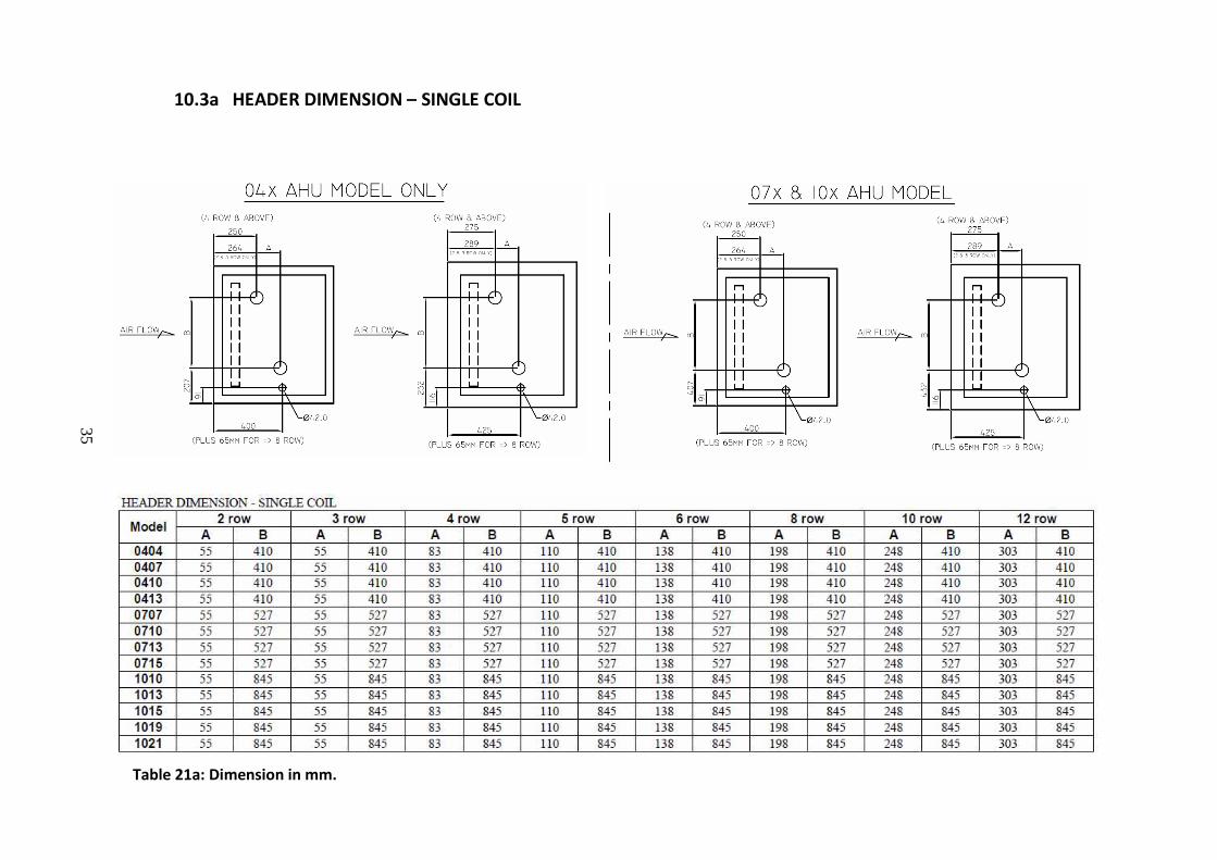
Table 21a: Dimension in mm.
10.3a HEADER DIMENSION – SINGLE COIL

36
10.3b HEADER DIMENSION – 2 LAYER COIL
Table 21b: Dimension in mm.

37
10.3c HEADER DIMENSION – 3 LAYER COIL
Table 21c: Dimension in mm.

38
11.0 HEAT RECOVERY WHEEL SPECIFICATION
Heat recovery wheel is available in DDM AHU selection software. AHU with HRW consists of two sections:
return air side and supply air side. The arrangement is as below. To install the heat wheel in air handling
unit, an empty section is required. The size of heat wheel has to be considered for the specification
drawing. Besides, spaces between heat wheel section and the coil section must be considered to ensure
the most efficient heat transfer between air flow and coil medium at the coil section beside the access for
maintenance.
Figure 26

39
12.0 FILTER
12.1 Standard Filter Specification
Model
Filter Media Size and Quantity
Sliding Filter Frame Universal Filter Frame
24" x 24" 24" x 12" Total
Area(m2
24" x 24" 24" x 12" Total Area
(m2 Qty Area (m
2 Qty Area (m
2 Qty Area (m
2 Qty Area (m
2
0404 1 0.37 0 0.00 0.37 1 0.37 0 0.00 0.37
0407 1 0.37 1 0.19 0.56 1 0.37 1 0.19 0.56
0410 2 0.74 0 0.00 0.74 2 0.74 0 0.00 0.74
0413 2 0.74 1 0.19 0.93 2 0.74 1 0.19 0.93
0707 1 0.37 2 0.00 0.74 1 0.37 2 0.00 0.74
0710 2 0.74 2 0.19 1.11 2 0.74 2 0.19 1.11
0713 2 0.74 3 0.37 1.3 2 0.74 3 0.37 1.30
0715 3 1.11 3 0.37 1.67 3 1.11 3 0.37 1.67
1010 4 1.49 0 0.56 1.49 4 1.49 0 0.56 1.49
1013 4 1.49 2 0.56 1.86 4 1.49 2 0.56 1.86
1015 6 2.23 0 0.00 2.23 6 2.23 0 0.00 2.23
1019 6 2.23 2 0.37 2.6 6 2.23 2 0.37 2.60
1021 8 2.97 0 0.00 2.97 8 2.97 0 0.00 2.97
1315 6 2.23 3 0.37 2.79 6 2.23 3 0.37 2.79
1319 6 2.23 5 0.00 3.16 6 2.23 5 0.00 3.16
1321 8 2.97 4 0.56 3.71 8 2.97 4 0.56 3.71
1519 6 2.23 5 0.93 3.16 6 2.23 5 0.93 3.16
1521 8 2.97 4 0.74 3.71 8 2.97 4 0.74 3.71
1819 9 3.34 3 0.56 3.9 9 3.34 3 0.56 3.90
1821 12 4.46 0 0 4.46 12 4.46 0 0 4.46
1823 12 4.46 0 0 4.46 12 4.46 0 0 4.46
1827 15 5.58 0 0 5.58 12 4.46 3 0.56 5.02
2027 15 5.58 5 0.93 6.51 12 4.46 7 1.30 5.76
2033 18 6.69 6 1.11 7.80 15 5.58 8 1.49 7.06
2233 24 8.93 0 0 8.93 20 7.43 4 0.74 8.18
2239 28 10.41 0 0 10.41 24 8.93 4 0.74 9.66
2539 28 10.41 7 1.3 11.71 24 8.93 10 1.86 10.78
Table 28.

40
Table 30.
12.2 HEPA FILTER SPECIFICATION
Model
HEPA Filter Size c/w Frame and Quantity/unit
Size : 24" x 24" Size : 24" x 12" Total
Qty Area (m² Qty Area (m² Qty Area (m²
0404 1 0.37 0 0.00 1 0.37
0407 1 0.37 1 0.19 2 0.56
0410 2 0.74 0 0.00 2 0.74
0413 2 0.74 0 0.00 2 0.74
0707 1 0.37 2 0.37 3 0.74
0710 2 0.74 2 0.37 4 1.11
0713 2 0.74 2 0.37 4 1.11
0715 2 0.74 3 0.56 5 1.30
1010 4 1.49 0 0.00 4 1.49
1013 4 1.49 0 0.00 4 1.49
1015 4 1.49 2 0.37 6 1.86
1019 6 2.23 0 0.00 6 2.23
1021 6 2.23 2 0.37 8 2.60
1315 4 1.49 2 0.37 6 1.86
1319 6 2.23 0 0.00 6 2.23
1321 6 2.23 2 0.37 8 2.60
1519 6 2.23 3 0.56 9 2.79
1521 6 2.23 5 0.93 11 3.16
1819 9 3.34 0 0.00 9 3.34
1821 9 3.34 3 0.56 12 3.90
1823 12 4.46 0 0.00 12 4.46
1827 12 4.46 3 0.56 15 5.02
2027 12 4.46 7 1.30 19 5.76
2033 15 5.57 8 1.49 23 7.06
2233 15 5.57 8 1.49 23 7.06
2239 18 6.69 6 1.11 24 7.80
2539 24 8.92 0 0.00 24 8.92

J&E Hall Refrigeration Sdn Bhd(A member of DAIKIN group)
Lot 10, Jalan Perusahaan 8, Kawasan Perusahaan Pekan Banting, 42700 Banting, Selangor Darul Ehsan.
Tel: +603 31872911 Fax: +603 3187 8897 Website: www.jehall.com.my