by shaela rahman, baker hughes - amazon s3 · at baker hughes, a top-tier ... vhdl was the language...
TRANSCRIPT
6
FPGA designs are becoming too large to verify by visually checking waveforms, as the functionality has become beyond easy comprehension. At Baker Hughes, a top-tier oilfield service company, we primarily design small scale FPGA designs, typically less than 100 thousand gates, but our designs are growing in size and complexity. As well, they are part of more complex systems that require long lab integration times.
For these reasons, our FPGA design and verification team needed to find a new methodology that does not rely on visual checks, shortens our lab integration testing time, standardizes our testbenches, and makes our functional verification more robust.
VHDL was the language of choice for both our RTL design and testbench, but there was no standardization or robustness for our testbenches. We did not reuse our testbenches, though we had the intention to do so. We knew the Universal Verification Methodology (UVM) provided testbench standardization, which is why we wanted to investigate the adoption of a UVM-based flow.
In order to justify the transition from a VHDL to a UVM testbench, we conducted an evaluation to compare the pros and cons of using three styles of testbench: a simple VHDL testbench, an advanced VHDL testbench, and a UVM testbench. The metrics used to evaluate them were the level of code coverage achieved, the reusability of testbench components, and the ease of creating different stimuli.
PREVIOUS DESIGN AND VERIFICATION FLOW Most of our designs are debugged during lab integration testing. Our design and verification flow begins with an RTL design and a testbench created in VHDL. We apply simple stimuli to our design under test (DUT) and visually inspect the waveforms using a simulator. Once we achieve some confidence in our visual inspection, we go into the lab and download the code to an FPGA and integrate it into the rest of the design, which includes several PCBs. If we see the FPGA is not
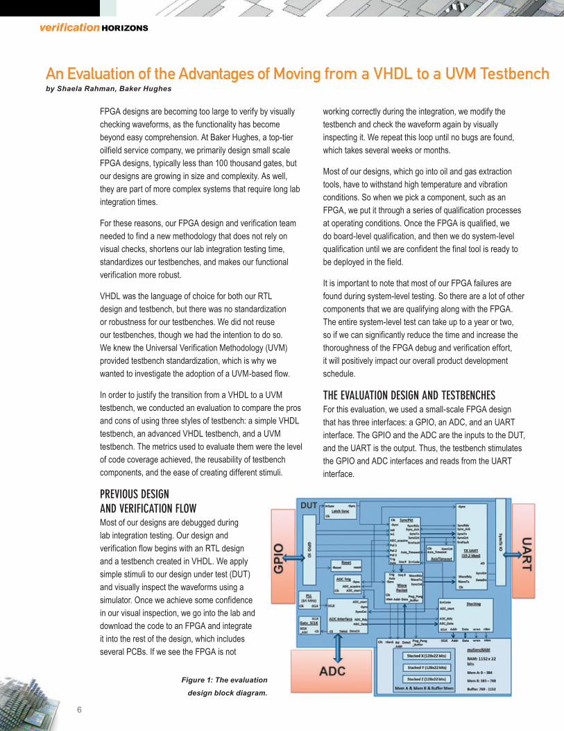
Figure 1: The evaluation
design block diagram.
working correctly during the integration, we modify the testbench and check the waveform again by visually inspecting it. We repeat this loop until no bugs are found, which takes several weeks or months.
Most of our designs, which go into oil and gas extraction tools, have to withstand high temperature and vibration conditions. So when we pick a component, such as an FPGA, we put it through a series of qualification processes at operating conditions. Once the FPGA is qualified, we do board-level qualification, and then we do system-level qualification until we are confident the final tool is ready to be deployed in the field.
It is important to note that most of our FPGA failures are found during system-level testing. So there are a lot of other components that we are qualifying along with the FPGA. The entire system-level test can take up to a year or two, so if we can significantly reduce the time and increase the thoroughness of the FPGA debug and verification effort, it will positively impact our overall product development schedule.
THE EVALUATION DESIGN AND TESTBENCHES For this evaluation, we used a small-scale FPGA design that has three interfaces: a GPIO, an ADC, and an UART interface. The GPIO and the ADC are the inputs to the DUT, and the UART is the output. Thus, the testbench stimulates the GPIO and ADC interfaces and reads from the UART interface.
An Evaluation of the Advantages of Moving from a VHDL to a UVM Testbench by Shaela Rahman, Baker Hughes
7
For the evaluation, we first created a simple VHDL testbench, then transitioned that into a VHDL advanced testbench, and finally transitioned that to a UVM testbench.
Through this transition process, all three testbenches remained equivalent in terms of what they model. Whatever was modeled in the simple VHDL testbench was ported over to the advanced VHDL testbench and then to the UVM testbench. Even though the level of code coverage achieved is one of the metrics, no specific changes were made for the sole purpose of increasing code coverage as that would have compromised the commensurability of the testbench comparisons.
The simple VHDL testbench used RTL-style processes. The advanced VHDL testbench used records for the GPIO, ADC, and UART transactions and used procedures for stimulus and checking. In the UVM testbench, components called “agents” were used for the GPIO, ADC, and UART interfaces. A key aspect of the UVM environment we built was that the test sequences for stimulus generation were isolated. Now let’s look at each in more detail.
TESTBENCH 1: A SIMPLE VHDL TESTBENCH In this testbench, the DUT, stimulus, and checks were modeled in RTL-style processes. The checks were modeled mostly after debugging in the lab.
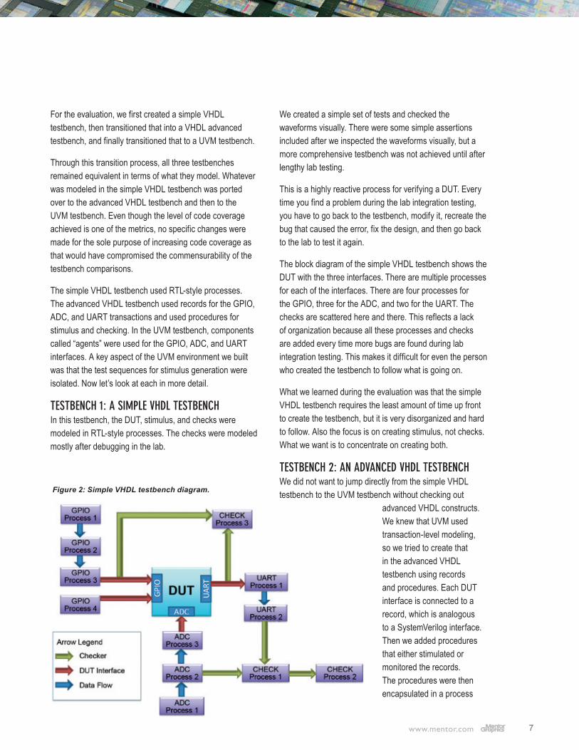
Figure 2: Simple VHDL testbench diagram.
We created a simple set of tests and checked the waveforms visually. There were some simple assertions included after we inspected the waveforms visually, but a more comprehensive testbench was not achieved until after lengthy lab testing.
This is a highly reactive process for verifying a DUT. Every time you find a problem during the lab integration testing, you have to go back to the testbench, modify it, recreate the bug that caused the error, fix the design, and then go back to the lab to test it again.
The block diagram of the simple VHDL testbench shows the DUT with the three interfaces. There are multiple processes for each of the interfaces. There are four processes for the GPIO, three for the ADC, and two for the UART. The checks are scattered here and there. This reflects a lack of organization because all these processes and checks are added every time more bugs are found during lab integration testing. This makes it difficult for even the person who created the testbench to follow what is going on.
What we learned during the evaluation was that the simple VHDL testbench requires the least amount of time up front to create the testbench, but it is very disorganized and hard to follow. Also the focus is on creating stimulus, not checks. What we want is to concentrate on creating both.
TESTBENCH 2: AN ADVANCED VHDL TESTBENCH We did not want to jump directly from the simple VHDL testbench to the UVM testbench without checking out
advanced VHDL constructs. We knew that UVM used transaction-level modeling, so we tried to create that in the advanced VHDL testbench using records and procedures. Each DUT interface is connected to a record, which is analogous to a SystemVerilog interface. Then we added procedures that either stimulated or monitored the records. The procedures were then encapsulated in a process
An Evaluation of the Advantages of Moving from a VHDL to a UVM Testbench by Shaela Rahman, Baker Hughes
8
designated to call only that procedure. The self-checking portion (what’s called the scoreboard in UVM) is modeled in a separate checker procedure. There were three processes to generate the stimulus and monitor the bus activity and one process to validate the results.
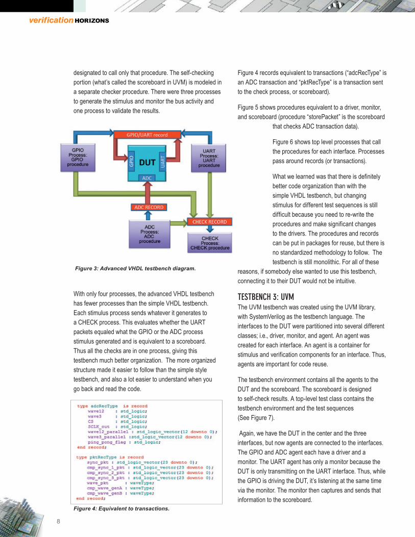
Figure 3: Advanced VHDL testbench diagram.
With only four processes, the advanced VHDL testbench has fewer processes than the simple VHDL testbench. Each stimulus process sends whatever it generates to a CHECK process. This evaluates whether the UART packets equaled what the GPIO or the ADC process stimulus generated and is equivalent to a scoreboard. Thus all the checks are in one process, giving this testbench much better organization. The more organized structure made it easier to follow than the simple style testbench, and also a lot easier to understand when you go back and read the code.
Figure 4: Equivalent to transactions.
Figure 4 records equivalent to transactions (“adcRecType” is an ADC transaction and “pktRecType” is a transaction sent to the check process, or scoreboard).
Figure 5 shows procedures equivalent to a driver, monitor, and scoreboard (procedure “storePacket” is the scoreboard
that checks ADC transaction data).
Figure 6 shows top level processes that call the procedures for each interface. Processes pass around records (or transactions).
What we learned was that there is definitely better code organization than with the simple VHDL testbench, but changing stimulus for different test sequences is still difficult because you need to re-write the procedures and make significant changes to the drivers. The procedures and records can be put in packages for reuse, but there is no standardized methodology to follow. The testbench is still monolithic. For all of these
reasons, if somebody else wanted to use this testbench, connecting it to their DUT would not be intuitive.
TESTBENCH 3: UVM The UVM testbench was created using the UVM library, with SystemVerilog as the testbench language. The interfaces to the DUT were partitioned into several different classes; i.e., driver, monitor, and agent. An agent was created for each interface. An agent is a container for stimulus and verification components for an interface. Thus, agents are important for code reuse.
The testbench environment contains all the agents to the DUT and the scoreboard. The scoreboard is designed to self-check results. A top-level test class contains the testbench environment and the test sequences (See Figure 7).
Again, we have the DUT in the center and the three interfaces, but now agents are connected to the interfaces. The GPIO and ADC agent each have a driver and a monitor. The UART agent has only a monitor because the DUT is only transmitting on the UART interface. Thus, while the GPIO is driving the DUT, it’s listening at the same time via the monitor. The monitor then captures and sends that information to the scoreboard.

9
In the UVM testbench, information about the interfaces at the system level is passed around using transactions. These transactions are generated by the test sequences. The test sequences come up with different test stimuli for the GPIO and ADC transactions. The transactions are generated and passed into the agents, and then passed into the DUT. A copy of that gets passed into the scoreboard.
The scoreboard does automatic checking and is always checking whether the UART packets are equal to the ADC and GPIO transactions.
Critically, the test sequences are isolated from the agents and the testbench environment. This is very important because when you change the test sequences, you don’t
have to change any of the agent’s drivers.
In comparison, with the VHDL testbenches, you have to do significant changes to the drivers, procedures, and processes, which you won’t do unless you find bugs in the lab. It takes too long to do otherwise.
This is a big advantage of the
10
UVM testbench. Because the test sequences are isolated in UVM, you can create another test very quickly in order to improve your testing. In this case, we were able to go from 79% to 85% code coverage by changing the test sequence alone — from ordered to randomized triggers.
Changing a test sequence and re-running code coverage in the UVM environment takes less than a day. In comparison, with a VHDL style testbench it would take several weeks to achieve a similar improvement.
The lessons learned with the UVM testbench are that the test sequences are isolated from the structural testbench and that gives better control in that you can change the stimulus without redesigning the agents. Code coverage was increased easily by changing the test sequence. Using UVM supports an industry standard, so it will encourage testbench standardization. For VHDL there is no testbench industry standard. UVM also improves reusability through object oriented programming (OOP) features, such as inheritance, and by using override components, which are allowed by polymorphism. These are additional benefits of UVM.
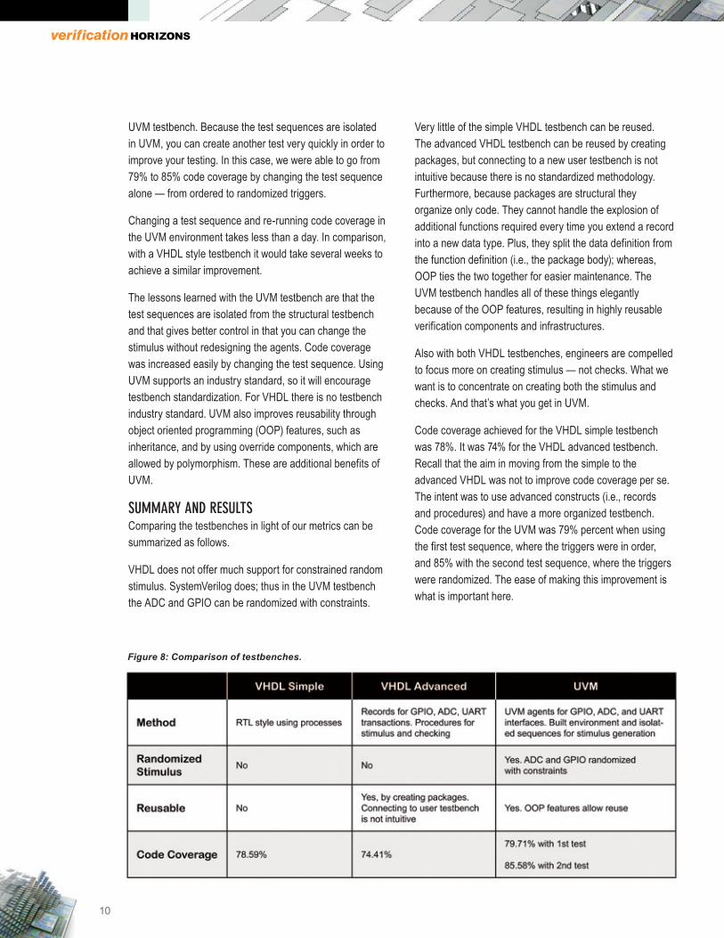
SUMMARY AND RESULTS Comparing the testbenches in light of our metrics can be summarized as follows.
VHDL does not offer much support for constrained random stimulus. SystemVerilog does; thus in the UVM testbench the ADC and GPIO can be randomized with constraints.
Very little of the simple VHDL testbench can be reused. The advanced VHDL testbench can be reused by creating packages, but connecting to a new user testbench is not intuitive because there is no standardized methodology. Furthermore, because packages are structural they organize only code. They cannot handle the explosion of additional functions required every time you extend a record into a new data type. Plus, they split the data definition from the function definition (i.e., the package body); whereas, OOP ties the two together for easier maintenance. The UVM testbench handles all of these things elegantly because of the OOP features, resulting in highly reusable verification components and infrastructures.
Also with both VHDL testbenches, engineers are compelled to focus more on creating stimulus — not checks. What we want is to concentrate on creating both the stimulus and checks. And that’s what you get in UVM.
Code coverage achieved for the VHDL simple testbench was 78%. It was 74% for the VHDL advanced testbench. Recall that the aim in moving from the simple to the advanced VHDL was not to improve code coverage per se. The intent was to use advanced constructs (i.e., records and procedures) and have a more organized testbench. Code coverage for the UVM was 79% percent when using the first test sequence, where the triggers were in order, and 85% with the second test sequence, where the triggers were randomized. The ease of making this improvement is what is important here.

11
The UVM testbench increases robustness of functional verification, and allows you to create flexible, adaptable, scalable testbenches. It offers quantifiable, measurable progress, and changing test sequences can be used to easily increase code coverage. UVM reporting, which we did not discuss, is very powerful and was used in our reviews.
Ultimately, we believe that UVM will reduce our tool integration time by allowing us to attain our ultimate goal of decreasing the time of our lab integration cycles.
Finally, UVM takes away the focus from doing visual waveform checking, and that’s important because FPGAs are becoming too big to check the waveforms visually. Therefore, eventually we are going to have to use UVM for the verification of FPGAs.

VERIFICATION ACADEMY
The Most Comprehensive Resource for Verification Training
25 Video Courses Available Covering
• Formal Verification• Intelligent Testbench Automation• Metrics in SoC Verification• Verification Planning• Introductory, Basic, and Advanced UVM• Assertion-Based Verification• FPGA Verification• Testbench Acceleration• PowerAware Verification• Analog Mixed-Signal Verification
UVM and Coverage Online Methodology Cookbooks
Discussion Forum with more than 6000 topics
UVM Connect and UVM Express Kits
www. verificationacademy.com
25 Video Courses Available Covering
• Formal Verification• Intelligent Testbench Automation• Metrics in SoC Verification• Verification Planning• Introductory, Basic, and Advanced UVM• Assertion-Based Verification• FPGA Verification• Testbench Acceleration• PowerAware Verification• Analog Mixed-Signal Verification
UVM and Coverage Online Methodology Cookbooks
Discussion Forum with more than 6500 topics
UVM Connect and UVM Express Kits
www. verificationacademy.com

Editor: Tom FitzpatrickProgram Manager: Rebecca Granquist
Wilsonville Worldwide Headquarters8005 SW Boeckman Rd.Wilsonville, OR 97070-7777Phone: 503-685-7000
To subscribe visit: www.mentor.com/horizons
To view our blog visit:VERIFICATIONHORIZONSBLOG.COM