by order of the secretary air force...
TRANSCRIPT

BY ORDER OF THE SECRETARY
OF THE AIR FORCE
AIR FORCE INSTRUCTION 11-2F-15
VOLUME 3
18 SEPTEMBER 2014
KADENA AIR BASE
Supplement
10 NOVEMBER 2015
Flying Operations
F-15--OPERATIONS PROCEDURES
COMPLIANCE WITH THIS PUBLICATION IS MANDATORY
ACCESSIBILITY: Publications and forms are available on the e-Publishing website at
www.e-Publishing.af.mil for downloading or ordering.
RELEASABILITY: There are no releasability restrictions on this publication.
OPR: ACC/A3TO
Supersedes: AFI11-2F-15V3, 21 July 2004
Certified by: HQ USAF/A3O
(Brig Gen Giovanni K. Tuck)
Pages: 131
(KADENAAB)
OPR: 18 OG/OGV
Supersedes: AFI11-2F-15V3_ KADENAAB
SUP, 13 September 2011
Certified by: 18 OG/CDF
(Col Joel O. Cook)
Pages: 41
This publication establishes effective and safe operations of the F-15 and implements AFPD 11-
2, Aircraft Rules and Procedures; AFPD 11-4, Aviation Service; and AFI 11-202V3, General
Flight Rules. It establishes the minimum Air Force operations procedures for personnel
performing duties in the F-15. It applies to all F-15 A-D units, including the Air Force Reserve
and Air National Guard (ANG), except where noted otherwise. This publication may be
supplemented at any level, but all supplements must be routed to the Office of Primary
Responsibility (OPR) listed above for coordination prior to certification and approval. Refer
recommended changes and questions about this publication to the OPR listed above using the AF
Form 847, Recommendation for Change of Publication; route AF Forms 847 from the field
through the appropriate chain of command. Requests for waivers must be submitted to the OPR
listed above, or as otherwise stipulated within this publication, for consideration and approval.
The use of the name or mark of any specific manufacturer, commercial product, commodity, or
service in this publication does not imply endorsement by the Air Force. This publication

2 AFI11-2F-15V3_KADENAABSUP 10 NOVEMBER 2015
incorporates Air Combat Command (ACC), Air National Guard (ANG), Pacific Air Forces
(PACAF) and United States Air Forces in Europe (USAFE) supplements using the paragraph
supplementation method. Supplemental material is highlighted in BOLD italics and prefaced
with [ACC], [ANG], [PACAF] or [USAFE] as applicable. Waiver authority to this publication
is established in paragraph 1.3. See paragraph 1.5 for guidance on submitting comments and
suggesting improvements. This instruction requires the collection or maintenance of information
protected by the Privacy Act of 1974. The authority to collect and maintain the records
prescribed in this instruction are 37 USC 301a, Incentive Pay; Public Law 92-204
(Appropriations Act for 1973), Section 715; Public Law 93-570 (Appropriations Act for 1974);
Public Law 93-294 (Aviation Career Incentive Act of 1974); DOD Instruction 7730.57, Aviation
Career Incentive Act of 1974 and Required Annual Report; AFI 11-401, Aviation Management;
and E.O. 9397 (SSN) as amended by Executive Order 13478, Amendments to Executive Order
9397 Relating to Federal Agency Use of Social Security Numbers, November 18, 2008. System
of records notice F011 AF/XOA, Aviation Resource Management System (ARMS), applies.
Ensure all records created as a result of processes prescribed in this publication are maintained in
accordance with Air Force Manual (AFMAN) 33-363, Management of Records, and disposed of
in accordance with the Air Force Records Disposition Schedule (RDS) located in the Air Force
Records Information Management System (AFRIMS).
Note: This instruction contains references to field (subordinate level) publications and forms
which, until converted to departmental level publications and forms, may be obtained from the
respective Major Command (MAJCOM) publication distribution office.
(KADENAAB) Air Force Instruction (AFI) 11-2F-15, Volume 3, F-15--Operations
Procedures, 18 September 2014, is supplemented as follows: It establishes local guidance and
procedures for operating fighter aircraft at Kadena Air Base (AB). It applies to 18th Wing (18
WG) and partner/visiting units at Kadena AB. This publication does not apply to the Air
National Guard or US Air Force Reserve units and members. It is a standalone publication and
must be read in conjunction with AFI11-2F-15, Volume 3. Refer recommended changes and
questions about this publication to 18 OG/OGV, the Office of Primary Responsibility (OPR),
using the AF Form 847, Recommendation for Change of Publication. Ensure that all records
created as a result of processes prescribed in this publication are maintained in accordance with
Air Force Manual (AFMAN) 33-363, Management of Records, and disposed of in accordance
with Air Force Records Information Management System (AFRIMS) Records Disposition
Schedule (RDS) located at https://www.my.af.mil/gcss-af61a/afrims/afrims/.
SUMMARY OF CHANGES
This instruction has been substantially revised and must be completely reviewed. Major changes
include: new Chapter 1 title and content; changes waiver authority for those forces presented to
a Commander, Air Force Forces (COMAFFOR); adds Air-to-Air Interrogator System (AAI) use
guidance, adds fuel conservation guidance, adds long-term structural health mitigation measures;
adds Chapter 6 Air-to-Surface Weapons Employment for High Angle Strafe (HAS), Basic
Surface Attack (BSA) and Maritime Air Support (MAS) missions; adds briefing guide
attachments for HAS and BSA/MAS missions; complies with Headquarters (HQ) USAF
direction to capture Chemical, Biological, Nuclear and High-Yield Explosive (CBRNE)

AFI11-2F-15V3_KADENAABSUP 10 NOVEMBER 2015 3
information from rescinded AFI 10-2602 by creating a new Attachment; changes Crew
Coordination/Passenger/Ground Crew Briefing Guide to emphasize oxygen mask emergencies;
removes items now covered by changes to Instructions and Technical Orders; updates avionics
and weapons system terms to match current suite upgrades; changes all instances of Knots
Calibrated Airspeed (KCAS) to Knots Indicated Airspeed (KIAS); adds non-visual formation
discussion; makes numerous administrative changes; increases standardization with other
Combat Air Forces (CAF) 11-2MDS Volume 3s.
(KADENAAB) This document has been substantially revised and must be completely reviewed.
Major changes include the removal of all local F-15 administrative standards and techniques,
which have been compiled as the 18OG F-15 Administrative Standards pamphlet. What remains
is purely regulatory in nature, and cannot be briefed “non-standard”. This revision incorporates
several recent Flight Crew Information Files (FCIFs) and write-in changes due to local airspace
restructuring. Removed from this document are all references to duplicate information located in
Kadena Air Base Instruction (KABI) 13-204, Airfield Operating Instruction, regarding local area
operations both in flight and on the ground. It assumes a working knowledge of many AFIs and
relies heavily on AFTTP 3-3.F-15, Combat Aircraft Fundamentals, F-15, for standards.
Chapter 1— GENERAL GUIDANCE 10
1.1. References, Abbreviations, Acronyms, and Terms. ................................................ 10
1.2. Responsibilities. ...................................................................................................... 10
1.3. Waivers. .................................................................................................................. 10
1.4. Deviations. .............................................................................................................. 10
1.5. Processing Changes. ............................................................................................... 10
Chapter 2— MISSION PLANNING 11
2.1. Responsibilities. ...................................................................................................... 11
2.2. General Procedures. ................................................................................................ 11
2.3. Map/Chart Preparation. ........................................................................................... 11
2.4. Briefing/Debriefing. ................................................................................................ 12
2.5. Unit Developed Checklists and Local Pilot Aids.................................................... 14
2.6. Stowing Equipment in Bay 5. ................................................................................. 15
2.7. G-suit Use. .............................................................................................................. 15
Chapter 3— NORMAL OPERATING PROCEDURES 16
3.1. Ground Communications. ....................................................................................... 16

4 AFI11-2F-15V3_KADENAABSUP 10 NOVEMBER 2015
3.2. Ground Visual Signals. ........................................................................................... 16
3.3. Preflight. ................................................................................................................. 16
3.4. Ground Operations. ................................................................................................. 17
3.5. Flight Lineup. .......................................................................................................... 17
3.6. Before Takeoff Checks. .......................................................................................... 17
3.7. Takeoff. ................................................................................................................... 17
3.8. Formation Takeoff. ................................................................................................. 18
3.9. Join-up/Rejoin. ........................................................................................................ 18
3.10. Formation, General. ................................................................................................ 19
3.11. Tactical Formation. ................................................................................................. 20
3.12. Chase Formation. .................................................................................................... 21
3.13. Show Formation. ..................................................................................................... 21
3.14. Maneuvering Parameters. ....................................................................................... 22
3.15. Ops Checks. ............................................................................................................ 22
3.16. Radio Procedures. ................................................................................................... 23
3.17. Change of Aircraft Control. .................................................................................... 24
3.18. General Low Altitude Procedures. .......................................................................... 24
3.19. Air Refueling. ......................................................................................................... 26
3.20. Night Procedures. .................................................................................................... 26
3.21. Night Vision Goggles (NVG) Procedures. ............................................................. 27
3.22. Fuel Requirements. ................................................................................................. 29
3.23. Approaches and Landings. ...................................................................................... 29
3.24. Overhead Traffic Patterns. ...................................................................................... 30
3.25. Tactical Overhead Traffic Patterns. ........................................................................ 30
3.26. Touch-and-Go Landings. ........................................................................................ 30
3.27. Low Approaches. .................................................................................................... 30

AFI11-2F-15V3_KADENAABSUP 10 NOVEMBER 2015 5
3.28. Closed Traffic Patterns. .......................................................................................... 31
3.29. Back Seat Approaches and Landings. ..................................................................... 31
3.30. Formation Approaches and Landings. .................................................................... 31
3.31. After Shutdown Procedures. ................................................................................... 32
3.32. Refer to Table 3. ..................................................................................................... 32
Table 3.1. Weather Minimum Summary (Feet/NM/KM). ....................................................... 32
3.33. Refer to Table 3. ..................................................................................................... 32
Table 3.2. Minimum Altitude Summary (in Feet AGL). ......................................................... 33
Chapter 4— INSTRUMENT PROCEDURES 34
4.1. Approach Category. ................................................................................................ 34
4.2. Takeoff and Join-up. ............................................................................................... 34
4.3. Trail Procedures. ..................................................................................................... 34
4.4. Formation Break-up. ............................................................................................... 37
4.5. Formation Penetration. ............................................................................................ 37
4.6. Formation Approach. .............................................................................................. 37
4.7. Simulated Instrument Flight. .................................................................................. 37
4.8. Use of the Heads Up Display (HUD). .................................................................... 37
4.9. Use of the Joint Helmet Mounted Cueing System (JHMCS). ................................ 37
Chapter 5— AIR-TO-AIR WEAPONS EMPLOYMENT 38
5.1. References. .............................................................................................................. 38
5.2. Simulated Gun Employment. .................................................................................. 38
5.3. Maneuvering Limitations. ....................................................................................... 38
5.4. Aerial Gunnery Tow Procedures. ........................................................................... 38
5.5. NORAD VID Procedures. ...................................................................................... 40
Chapter 6— AIR-TO-SURFACE WEAPONS EMPLOYMENT 41
6.1. References. .............................................................................................................. 41

6 AFI11-2F-15V3_KADENAABSUP 10 NOVEMBER 2015
6.2. Weapons Delivery Parameters. ............................................................................... 41
6.3. Simulated Attacks against Range, Off-Range or Manned Targets. ........................ 41
Chapter 7— ABNORMAL OPERATING PROCEDURES 42
7.1. General. ................................................................................................................... 42
7.2. Ground Aborts. ....................................................................................................... 42
7.3. Takeoff Aborts. ....................................................................................................... 42
7.4. Air Aborts. .............................................................................................................. 43
7.5. Engine Malfunctions. .............................................................................................. 44
7.6. Radio Failure. .......................................................................................................... 44
7.7. Severe Weather Penetration. ................................................................................... 45
7.8. Lost Wingman Procedures. ..................................................................................... 45
7.9. Spatial Disorientation (SD). .................................................................................... 46
7.10. Armament System Malfunctions. ........................................................................... 47
7.11. Post Arresting Gear Engagement Procedures. ........................................................ 48
7.12. In-flight Practice of Emergency Procedures. .......................................................... 48
7.13. Search and Rescue (SARCAP) Procedures. ........................................................... 49
7.14. Lateral Asymmetry. ................................................................................................ 49
Table 7.1. Asymmetry ROTs. .................................................................................................. 50
Chapter 8— LOCAL OPERATING PROCEDURES 51
8.1. This chapter is reserved for unit local operating procedures. ................................. 51
Chapter 8—(KADENAAB) LOCAL OPERATING PROCEDURES 53
Section 8A—(KADENAAB) Introduction 53
8.1. (KADENAAB) Scope. ............................................................................................. 53
8.2. (Added-KADENAAB) Deviations. ......................................................................... 53
8.3. (Added-KADENAAB) References. ......................................................................... 53
8.4. (Added-KADENAAB) Changes. ............................................................................. 53

AFI11-2F-15V3_KADENAABSUP 10 NOVEMBER 2015 7
Section 8B—(KADENAAB) General Policy 53
8.5. (Added-KADENAAB) 18 OG Standards. ............................................................... 53
8.6. (Added-KADENAAB) Flight-Duty Period Limitations. ......................................... 53
8.7. (Added-KADENAAB) Go/No-Go Procedures. ....................................................... 53
8.8. (Added-KADENAAB) Situational Emergency Procedure Training (SEPT). ......... 53
8.9. (Added-KADENAAB) Publications. ....................................................................... 54
8.10. (Added-KADENAAB) Life Support Equipment. .................................................... 54
8.11. (Added-KADENAAB) Command and Control. ...................................................... 55
8.12. (Added-KADENAAB) Fuel Requirements. ............................................................ 55
Table 8.1. (Added-KADENAAB) Fuel Required. .................................................................... 56
8.13. (Added-KADENAAB) Weather. ............................................................................. 56
8.14. (Added-KADENAAB) Bird Watch Condition. ....................................................... 56
Section 8C—(KADENAAB) Ground Operations 57
8.15. (Added-KADENAAB) Preflight. ............................................................................ 57
8.16. (Added-KADENAAB) Ground Operations. ............................................................ 57
8.17. (Added-KADENAAB) Taxiing. .............................................................................. 58
Figure 8.1. (Added-KADENAAB) Taxi Out. ............................................................................ 59
8.18. (Added-KADENAAB) Before Takeoff. .................................................................. 59
Section 8D—(KADENAAB) Flying Operations 59
8.19. (Added-KADENAAB) Takeoff. .............................................................................. 59
8.20. (Added-KADENAAB) In-Flight Procedures........................................................... 59
Figure 8.2. (Added-KADENAAB) HOTEL ONE Departure Procedures.................................. 60
Figure 8.3. (Added-KADENAAB) HOTEL ONE Recovery Procedures. ................................. 61
Table 8.2. (Added-KADENAAB) Fuel Imbalances That Yield 5000 Ft-Lb Lateral
Asymmetry............................................................................................................... 63
8.21. (Added-KADENAAB) After Landing. .................................................................... 64
Figure 8.4. (Added-KADENAAB) Taxi Back. .......................................................................... 64
8 AFI11-2F-15V3_KADENAABSUP 10 NOVEMBER 2015
8.22. (Added-KADENAAB) Maintenance Debrief. ......................................................... 65
8.23. (Added-KADENAAB) C2. ...................................................................................... 65
8.24. (Added-KADENAAB) Night Procedures. ............................................................... 66
8.25. (Added-KADENAAB) Two/Four Ship Flight Lead Clarification........................... 66
Section 8E—(KADENAAB) Weapons Employment 66
8.26. (Added-KADENAAB) ALE-45 (CMD) Procedures. .............................................. 66
Section 8F—(KADENAAB) Abnormal Procedures 67
8.27. (Added-KADENAAB) Emergencies. ...................................................................... 67
8.28. (Added-KADENAAB) Divert Procedures. ............................................................. 69
Figure 8.5. (Added-KADENAAB) Nyutabaru Divert. .............................................................. 71
8.29. (Added-KADENAAB) F-15 Alternate Missions. .................................................... 72
8.30. (Added-KADENAAB) Cross Country and Deployment Flights. ............................ 72
8.31. (Added-KADENAAB) Hot Turn Operations. ......................................................... 72
Figure 8.6. (Added-KADENAAB) Hot Pits. ............................................................................. 73
AFI11-2F-15V3_KADENAABSUP 10 NOVEMBER 2015 9
Attachment 1— GLOSSARY OF REFERENCES AND SUPPORTING INFORMATION 74
Attachment 2— CHEMICAL, BIOLOGICAL, RADIOLOGICAL, NUCLEAR, AND
HIGH YIELD EXPLOSIVE (CBRNE) OPERATIONS 83
Attachment 3— GENERAL BRIEFING GUIDE 85
Attachment 4— SPECIAL SUBJECT BRIEFING GUIDE 87
Attachment 5— ADVANCED HANDLING/INSTRUMENT BRIEFING GUIDE 88
Attachment 6— AIR REFUELING BRIEFING GUIDE 89
Attachment 7— AIR COMBAT TRAINING (ACBT) / INTERCEPT BRIEFING GUIDE 91
Attachment 8— ESCORT MISSION BRIEFING GUIDE 95
Attachment 9— AERIAL GUNNERY TOW COORDINATION BRIEFING GUIDE 97
Attachment 10— AERIAL GUNNERY BRIEFING GUIDE 99
Attachment 11— LOW-LEVEL NAVIGATION BRIEFING GUIDE 101
Attachment 12— NVG BRIEFING GUIDE 103
Attachment 13— ALERT BRIEFING GUIDE 106
Attachment 14— HIGH ANGLE STRAFE (HAS) BRIEFING GUIDE 109
Attachment 15— MARITIME AIR SUPPORT (MAS) AND BASIC SURFACE ATTACK
(BSA) BRIEFING GUIDE 112
Attachment 16— CREW COORDINATION/PASSENGER/GROUND CREW BRIEFING
GUIDE 114
Attachment 17— MISSION DEBRIEFING GUIDE 116
Attachment 18—(Added-KADENAAB) LOCAL RADIO CALLS 117
Attachment 19—(Added-KADENAAB) F-15C TANKER ADMIN PROCEDURES 118
Attachment 20—(Added-KADENAAB) F-15 ALTERNATE MISSIONS 121
Attachment 21—(Added-KADENAAB) SURGE OPERATIONS 125
Attachment 22—(Added-KADENAAB) CROSS COUNTRY SAMPLE REQUEST 127
Attachment 23—(Added-KADENAAB) FITS GUIDANCE 129
Attachment 24—(Added-KADENAAB) 18 WG MESL 130

10 AFI11-2F-15V3_KADENAABSUP 10 NOVEMBER 2015
Chapter 1
GENERAL GUIDANCE
1.1. References, Abbreviations, Acronyms, and Terms.
1.1.1. See Attachment 1.
1.2. Responsibilities. (T-2).
1.2.1. This instruction, in conjunction with other governing directives, prescribes procedures
for operating F-15 aircraft under most circumstances. It is not a substitute for sound
judgment.
1.2.2. Procedures not specifically addressed may be accomplished if they enhance safe and
effective mission accomplishment.
1.3. Waivers. (T-2).
1.3.1. Unless another approval authority is cited, waiver authority for this volume is
MAJCOM/A3 or equivalent (e.g. COMAFFOR/A3 [COMAFFOR when AFI 11-202V3,
paragraph 1.6.2.3, stipulations are not met]).
1.3.2. Waivers are issued for a maximum of one year from the effective date.
1.3.3. COMAFFOR staff will notify HQ ACC/A3 and home station MAJCOM/A3 of
waivers within 72 hours of approval.
1.4. Deviations. (T-2).
1.4.1. In the case of an urgent requirement or aircraft emergency, the pilot in command
(PIC) will take appropriate action(s) to safely recover the aircraft.
1.4.2. If time permits, specific MAJCOM/A3 approval will be obtained for one time
deviations from these procedures.
1.5. Processing Changes. (T-1).
1.5.1. Submit recommended changes and questions about this publication through
MAJCOM channels to the OPR per AFI 11-215, USAF Flight Manuals Program (FMP)
using AF Form 847, Recommendation for Change of Publication.
1.5.2. The submitting MAJCOM will forward information copies of AF Forms 847 to all
other MAJCOMs that use this publication. Using MAJCOMs will forward comments on AF
Forms 847 to the OPR.
1.5.3. OPR will:
1.5.3.1. Coordinate all changes to the basic volume with affected MAJCOM/A3s.
1.5.3.2. Forward change recommendations to HQ AFFSA for staffing and HQ USAF/A3
approval.

AFI11-2F-15V3_KADENAABSUP 10 NOVEMBER 2015 11
Chapter 2
MISSION PLANNING
2.1. Responsibilities. (T-2).
2.1.1. The responsibility for mission planning is shared jointly by all flight members and the
operations and intelligence functions of fighter organizations.
2.2. General Procedures. (T-2).
2.2.1. Accomplish sufficient flight planning to ensure safe mission accomplishment to
include fuel requirements, map preparation, and takeoff/landing data.
2.2.1.1. [PACAF] Fly planned over water flights outside the local training area (i. e.,
deployments, cross countries, PDM inputs, etc.) as a two-ship minimum. OG/CC may
approve single-ship missions.
2.2.1.2. [USAFE] In addition, when applicable, pilots will consult the following for
mission planning:
2.2.1.2.1. DOD FLIP Planning Europe, Africa, and Middle East.
2.2.1.2.2. UK Military Low Fly Handbook.
2.2.1.2.3. UK Low Fly Notices to Airmen (NOTAMS).
2.2.1.2.4. UK Royal Flights.
2.2.1.2.5. AFI 11-202V3_USAFESUP_I, Attachment 5 CONTROL OF FIGHTER
AIRCRAFT FOR OFF STATION SORTIES/DIVERT.
2.2.1.2.6. ASRR, Airfield Suitability Report/Summary Airfield Restrictions.
2.2.1.2.7. AFI 13-212, volume 1/USAFE 1, USAFE Range Procedures.
2.2.1.2.8. AFPAM 11-216, Air Navigation
2.2.2. Fuel Conservation. Design procedures for optimal fuel use and efficiency
throughout all phases of mission execution. Incorporate enroute tasks to maximize use of
airborne training opportunities.
2.3. Map/Chart Preparation. (T-2).
2.3.1. Local Area Maps. A local area map is not required if the unit pilot aid includes
jettison areas, divert information, controlled bailout areas, and provides a local area map of
sufficient detail to remain within assigned training areas.
2.3.1.1. [USAFE] On flights from a deployed location, each aircrew will have available
a local map annotated with designated flying areas, emergency airfields, buffer zones,
control zones, and restricted or danger areas if this information is not available in the
aircrew aid.
2.3.2. Charts. Flight Information Publications (FLIP) enroute charts may be used instead of
maps on navigational flights within areas that are adequately covered by these charts.

12 AFI11-2F-15V3_KADENAABSUP 10 NOVEMBER 2015
2.3.2.1. [USAFE] Pilots may use UK Enroute Low Charts to supplement US DoD
Enroute Low charts as deemed necessary. Aircrew will reference UK Flight
Information Handbook for index and chart definitions contained on UK Enroute Low
chart.
2.3.3. Low Altitude Maps.
2.3.3.1. Reference AFMAN 11-217V2, Visual Flight Procedures, chapter 3, for Low
Altitude Map requirements and procedures.
2.3.3.2. For all flights conducted in the low-level structure (i.e. below 1,000 feet AGL or
as defined by host nation), each aircraft in the flight will contain a minimum of one Chart
Handbook Manual (CHUM) updated map of the low altitude route or training areas. The
map will be of a scale and quality that terrain features, hazards, and chart annotations are
of sufficient detail to allow navigation and safe mission accomplishment.
2.3.3.3. Highlight all manmade obstacles at or above the planned flight altitude.
2.3.3.4. IAW AFMAN 11-217V2, Chapter 3, annotate all maps with both an Emergency
Route Abort Altitude (ERAA) for the overall route/area and Minimum Safe Altitudes
(MSA) for each leg of the intended route of flight.
2.3.3.4.1. Compute the ERAA (a.k.a. Emergency Safe Altitude [ESA]) IAW
AFMAN 11-217V2, Chapter 3.
2.3.3.4.2. Compute the MSA at a minimum of 1,000 feet above the highest
obstacle/terrain (rounded up to the next 100 feet) within 5NM of the planned course
to include the aircraft turn radius.
2.3.3.5. [CONUS Only] Aircrew members flying under VFR or inside MTRs will
supplement existing mission planning materials (e.g., CHUM, FLIP AP/1B, etc.) IAW
AFI 11-202V3, ACCSUP, Chapter 2, mission planning requirements.
2.3.3.6. Low level charts and route books used during flight will be annotated with
location and dimensions of class B/C/D airspace, civil/military airfields and other
potential high density traffic areas (e.g., parachute activity areas and ultralight/hang
glider/glider sites, etc.). Within 5 NM of any planned VFR route or MTR lateral
boundary. Applicable airfield approach control frequencies in the vicinity of class B/C/D
airspace will be annotated and briefed on all such flights. In addition, annotate and brief
the intersection of other VR/IR routes (if applicable) and any other possible areas of
conflict.
2.3.3.7. Use of sectional aeronautical charts in flight is not required.
2.3.3.8. Aircrew members flying outside CONUS will follow gaining MAJCOM, theater
or host nation guidance on mission planning. If no gaining MAJCOM, theater or host
nation guidance exists, use the best charts or Falcon View overlay options available to
accomplish the requirements of paragraph 2.3.3.6
2.4. Briefing/Debriefing. (T-2).
2.4.1. Briefings. Flight leaders are responsible for presenting a logical briefing that will
promote safe, effective mission accomplishment. In addition to items required by AFI 11-
202V3, all briefings will include the following:

AFI11-2F-15V3_KADENAABSUP 10 NOVEMBER 2015 13
2.4.1.1. All pilots/crewmembers/passengers must attend the flight briefing unless
previously coordinated with unit supervisors. Anyone not attending the flight brief must
receive a briefing on mission events and emergency procedures.
2.4.1.2. Ensure brief start time provides adequate time to discuss required items and
accounts for mission complexity. As a minimum, begin briefs at least 1.5 hours before
scheduled takeoff. Alert briefs will start in sufficient time to be completed prior to
aircrew changeover.
2.4.1.3. Structure flight briefing to accommodate the capabilities of each flight member.
2.4.1.4. Briefers will reference applicable portions of briefing guides. Items listed may
be briefed in any sequence. Those items published in Air Force Instructions (AFI), Air
Force Tactics, Techniques, and Procedures manuals (AFTTP) or unit standards and
understood by all participants may be briefed as “standard.” Specific items not pertinent
to the mission do not need to be covered.
2.4.1.5. Takeoff and landing data (TOLD) will be annotated on mission data cards. The
minimum TOLD required is maximum abort speed (dry/wet), takeoff distance and speed,
single engine takeoff speed (SETOS), and normal/heavy weight landing distance
(dry/wet).
2.4.1.6. Review takeoff data, and ensure every member of the flight understands it. Place
particular emphasis on takeoff and abort factors during abnormal situations such as
short/wet runway, heavy gross weights, non-standard cable configurations, and abort
sequence in formation flights.
2.4.1.7. Ensure contracts, roles, and responsibilities of each flight member are
established, briefed, and debriefed.
2.4.1.8. Include mission priorities, significant rules (e.g., Rules of Engagement [ROE],
Special Instructions [SPINS], Training Rules [TRs]), task management, weather,
NOTAMs, and Emergency Procedures (EPs).
2.4.1.9. Ensure a formation deconfliction, blind, and get well plan for every phase of
flight is briefed and every flight member understands the plan (see para 3.10). All flight
members are responsible for executing this plan.
2.4.1.10. When dissimilar aircraft are flown in formation, brief flight responsibilities,
proper formation position (to ensure adequate wingtip clearance), and aircraft-unique
requirements for each phase of flight.
2.4.1.11. For missions using Night Vision Goggles (NVG), emphasize proper tuning,
use, and limitations. See para 3.21 for additional procedures.
2.4.1.12. For all low-level mission briefings, place emphasis on obstacle/ground
avoidance, altitude-warning features (low altitude warning tone) low altitude comfort
level, and complacency avoidance.
2.4.1.13. Brief an appropriate alternate mission for each flight. The alternate mission
must be less complex than the primary unless Wings have developed and published
standard alternate mission profiles. The one exception to this rule is that Air Combat
Maneuvers (ACM) may be briefed as an alternate mission from a Basic Fighter

14 AFI11-2F-15V3_KADENAABSUP 10 NOVEMBER 2015
Maneuvers (BFM) surge brief. Brief specific mission elements that differ from the
primary mission or published profiles. Mission elements or events may be modified and
briefed airborne as long as flight safety is not compromised. Flight leads will ensure all
flight members acknowledge changes. Do not fly unbriefed missions or events.
2.4.1.14. All missions will be debriefed.
2.4.2. Deployed Operations, Exercise, and Quick Turn Briefings. If all flight members
attend an initial or mass flight briefing, the flight lead on subsequent flights need brief only
those items that have changed from the previous flight(s).
2.4.2.1. [PACAF, USAFE] On multiple-go days when aircraft turn times do not allow
follow-on mission brief(s) and only the initial flight brief is accomplished for all goes, the
following guidance applies:
2.4.2.1.1. [PACAF, USAFE] Upgrade missions will be planned for the first sortie
flown. Subsequent missions will be of equal or less complexity with no upgrade
training planned without OG/CC approval.
2.4.2.1.2. [PACAF, USAFE] Participants in continuation training missions may fly
their primary or alternate missions in any sequence.
2.4.3. Briefing Guides. Mission briefing guides are contained in the Attachments. Units
may augment these guides as necessary. Pending development by a higher headquarters,
units that fly missions not covered by this instruction or its supplements will develop briefing
guides for those missions and submit them to MAJCOM/A3TO for review.
2.5. Unit Developed Checklists and Local Pilot Aids. (T-2).
2.5.1. Unit developed checklists may be used in lieu of flight manual checklists provided
they contain, as a minimum, all items (verbatim and in order) listed in the applicable
checklist.
2.5.2. Units will produce a pilot aid that, as a minimum, includes:
2.5.2.1. Briefing Guides.
2.5.2.2. Local radio channelization and airfield diagrams.
2.5.2.3. Emergency information (impoundment procedures, emergency action checklists,
no radio [NORDO] procedures, divert information, Search and Rescue procedures, and
On-Scene Commander [OSC] checklist).
2.5.2.4. Arresting gear information for divert bases.
2.5.2.5. Bailout and Jettison Areas.
2.5.2.6. Cross-country procedures to include: command and control, engine
documentation, JOAP samples, and aircraft servicing.
2.5.2.7. Other information as deemed necessary by the units. For example: stereo flight
plans, turnaround procedures, local training areas, instrument preflight, and alert
procedures.

AFI11-2F-15V3_KADENAABSUP 10 NOVEMBER 2015 15
2.6. Stowing Equipment in Bay 5. (T-2).
2.6.1. Stow containers or baggage with hard sides inside a Bay 5 cargo container. Without a
cargo container, stow only locally manufactured fabric intake covers and soft-sided personal
equipment baggage, such as hang-up or A-3 bags, in Bay 5. Items stowed in Bay 5 will be:
2.6.1.1. Positioned 1 foot aft of the top of the canopy thruster “catcher’s mitt.”
2.6.1.2. Forward of the trailing edge of the aft circuit breaker panel on the right wall of
Bay 5 (do not interfere with internal countermeasures set cables).
2.6.1.3. Below the top of the circuit breaker panels on the right wall of Bay 5.
2.6.1.4. Secured with non-stretchable cord in such a manner to prevent movement in all
three axes of motion. Place aircraft safety equipment and egress pins in locally
manufactured fabric bags and stow in panels 154L, 35, 47L and R or in the cockpit map
case. The pilot is responsible for ensuring items stowed in Bay 5 are loaded correctly and
properly secured. The carriage restrictions for the Bay 5 cargo container are identical to
the MXU-648/A cargo pod except for the airspeed restriction, which does not apply. This
guidance does not preclude the pilot from taking any action necessary for safety of flight.
Pilots will comply with the following restrictions:
2.6.1.4.1. Aircraft with items stowed in Bay 5, with or without a cargo container, are
restricted from performing aerobatics.
2.6.1.4.2. Training missions in aircraft with items stowed in Bay 5, with or without a
cargo container, are restricted to LIMITED maneuvering training rules. At no time
during the flight will the pilot execute zero or negative Gravitational Load Factor (G)
maneuvers unless safety of flight dictates.
2.7. G-suit Use. (T-2).
2.7.1. IAW AFI 11-301, Volume 1, ACC Supplement, Aircrew Flight Equipment (AFE)
Program, the following apply:
2.7.1.1. G-suit is required during all flights when 2 or more Gs are anticipated.
16 AFI11-2F-15V3_KADENAABSUP 10 NOVEMBER 2015
Chapter 3
NORMAL OPERATING PROCEDURES
3.1. Ground Communications. (T-2).
3.1.1. The pilot will accomplish the ground crew briefing (when required) in accordance
with the briefing guide contained in this instruction.
3.1.2. Prior to starting the JFS in a B/D model with the Rear Cockpit (RCP) occupied, the
pilot will get an “OK” signal from the rear cockpit occupant.
3.1.3. Normally, the pilot and ground crew will communicate using the intercom during all
engine start and pre-taxi checks. Use the intercom system, to the maximum extent possible,
anytime aircraft engines are operating and maintenance technicians are performing tasks on
the aircraft. Units with active air defense commitments may waive the use of intercom during
alert scrambles.
3.1.3.1. During the After Engine Start flight control checks, confirm the proper
movement and position of the flight control surfaces with the crew chief.
3.2. Ground Visual Signals. (T-2).
3.2.1. When ground intercom is not used, use visual signals IAW AFI 11-218, Aircraft
Operations and Movement on the Ground, and this instruction. All signals pertaining to
operation of aircraft systems will originate with the pilot. The crew chief will repeat the
given signals when it is safe to operate the system. The pilot should not activate any system
that could pose danger to the ground crew prior to receiving proper acknowledgment from
ground personnel. The following signals augment AFI 11-218.
3.2.1.1. JFS START. With clenched fist, pilot makes a pulling motion.
3.2.1.2. FLIGHT CONTROLS CHECK. Raise arm, clench fist, and make a stirring
motion.
3.2.1.3. BRAKE CHECK. Hold left or right arm horizontal, open hand and push
forward, breaking at the wrist (as in applying rudder pedal pressure with feet).
3.2.1.4. DEEC Check. With the fingers and thumb of each hand extended and joined at
the tips, open and close the fingers and thumbs of both hands simultaneously, simulating
nozzle opening and closing.
3.2.1.5. LOSS OF BRAKES WHILE TAXIING. Lower tailhook.
3.2.1.6. GUN ARMAMENT CHECK. Point index finger forward with thumb upward
simulating a pistol and shake head (yes or no).
3.3. Preflight. (T-2).
3.3.1. Do not carry baggage/equipment in an unoccupied F-15B/D rear cockpit (Exception:
forms/maps may be stowed in the map case).
3.3.2. In lieu of HHQ guidance (e.g. theater special instructions), set the emergency locator
beacon to AUTO while on local training missions and ferry flights.
AFI11-2F-15V3_KADENAABSUP 10 NOVEMBER 2015 17
3.4. Ground Operations. (T-2).
3.4.1. IAW AFTTP 3-3.F15, the minimum taxi interval is 150 feet staggered or 300 feet in
trail. Spacing may be reduced when holding short of or entering the runway.
3.4.2. Do not taxi during snow and/or icy conditions until the taxi route and runway have
been checked for safe conditions. In this case, taxi on the centerline with a minimum of 300
feet spacing.
3.4.2.1. [USAFE] Minimum runway condition reading (RCR) on taxiways for taxi
operations is RCR 10.
3.4.3. Maximum taxi speed during sharp turns is 10 knots. Above 10 knots the aircraft may
skid and/or depart the three-point attitude.
3.4.4. Quick Check and Arming. Keep hands in view of ground personnel during quick
check, arming or dearming operations. If the intercom system is not used during end of
runway (EOR) checks, the pilot will establish and maintain visual contact with the ground
personnel to allow the use of visual signals.
3.4.5. Do not taxi in front of aircraft being armed/de-armed with forward firing ordnance.
3.5. Flight Lineup. (T-2).
3.5.1. Flights will line up as appropriate based on weather conditions, runway conditions,
and runway width. Use a minimum of 500 feet spacing between separated elements/flights.
For formation takeoffs, wingmen must maintain wingtip clearance with their element leader.
If runway width precludes line-up with wingtip clearance between all aircraft in the flight,
use 500 feet spacing between elements or delay run-up until the preceding aircraft/element
releases brakes.
3.6. Before Takeoff Checks. (T-2).
3.6.1. Just prior to takeoff, all flight members will inspect each other for proper
configuration and any abnormalities. Wingmen will indicate they are ready for takeoff by a
head nod, radio call, or landing/taxi light signal.
3.7. Takeoff. (T-2).
3.7.1. Per MAJCOM guidance, OG/CC may waive RCR minimum for specified units
operating in cold weather locations, but in no case will takeoffs be conducted with an RCR of
less than 8.
3.7.1.1. [ACC/ANG] Do not takeoff if the RCR is less than 12.
3.7.2. On training missions, do not takeoff if the computed takeoff roll exceeds 80 percent of
the available runway. For single ship takeoffs, if the single ship computed military power
takeoff distance exceeds one-half of the available runway, takeoff using afterburner.
3.7.3. When operating from airfields equipped with a compatible, remotely operated cable,
ensure the departure end cable is raised for all takeoffs and landings, unless another departure
end cable is in place.

18 AFI11-2F-15V3_KADENAABSUP 10 NOVEMBER 2015
3.7.4. Use a minimum of 10 seconds (15 seconds when using afterburners) takeoff interval
between aircraft/elements. When joining “on top” use a minimum of 20 seconds takeoff
interval.
3.7.5. Wing/Group Commander or Ops Group Commander (Supervisor of flying [SOF] for
ANG) may approve intersection takeoffs if operational requirements dictate.
3.8. Formation Takeoff. (T-2).
3.8.1. Formation takeoffs are restricted to elements of two aircraft.
3.8.2. A qualified flight leader must lead a formation takeoff unless an Instructor Pilot (IP)
or flight lead qualified squadron supervisor is in the element.
3.8.3. Aircraft must be within 3,000 pounds weight of each other and symmetrically loaded.
Consider symmetrically loaded as those store loadings that do not require an abnormal trim
or control application to counter a roll or yaw during takeoff and acceleration to climb
airspeed.
3.8.4. In accordance with AFTTP 3-3.F15, for rolling formation takeoffs, the wingman must
be properly aligned on the runway prior to the flight lead advancing the throttle for takeoff.
3.8.4.1. [PACAF, USAFE] Rolling formation takeoffs are not authorized.
3.8.5. Do not make formation takeoffs when:
3.8.5.1. The runway width is less than 125 feet.
3.8.5.2. There is standing water, ice, slush, or snow on the runway.
3.8.5.3. The crosswind or gust component exceeds 15 knots.
3.8.5.4. Loaded with live munitions (excluding air-to-air missiles, 20mm ammunition,
and chaff/flares).
3.8.5.5. Ferrying aircraft from a contractor or AFMC facilities.
3.8.5.6. The computed takeoff roll exceeds 50% of the available runway.
3.9. Join-up/Rejoin. (T-2).
3.9.1. Day weather criteria for a visual flight rules (VFR) join-up underneath: ceiling 1,500
feet and visibility 3 miles.
3.9.2. Reference AFTTP 3-3.F15 for formation rejoin standard contracts (airspeeds, bank
angle, and formation position).
3.9.3. Battle Damage Checks. When circumstances permit, flight leads will direct a battle
damage check after each mission prior to or during return to base (RTB). Except at
night/Instrument Meteorological Conditions (IMC), this check is mandatory following the
expenditure of any ordnance (including all types of 20mm ammunition). Fly no closer than
fingertip formation spacing. Ensure deconfliction in accordance with AFTTP 3-3.F15.
3.9.4. For further join-up procedures, reference AFTTP 3-3.F15 and see Night Joinup
paragraph 3.20.3 and Chapter 4.
3.9.5. Air-to-Air Interrogator (AAI), Identification Friend or Foe/Selective
Identification Feature (IFF/SIF) Operation.

AFI11-2F-15V3_KADENAABSUP 10 NOVEMBER 2015 19
3.9.5.1. Military use of AAI Mode 4 interferes with ATC and civil Mode 3/C codes. F-
15 AAI use in the National Airspace System (NAS) will comply with the following:
3.9.5.2. To reduce the potential for adverse effects on Combat Identification, ATC, and
Traffic Collision Avoidance systems, aircrew will limit interrogations to the minimum
required for the mission.
3.9.5.3. For AAI operation within the United States and its Possessions (US&P), aircrew
will comply with the equipment and operational restrictions as specified in the applicable
Radio Frequency Authorization(s) which can be obtained from the unit spectrum
management office.
3.9.5.4. OCONUS, follow gaining MAJCOM, Theater, or Host Nation guidance for AAI
operation.
3.10. Formation, General. (T-2).
3.10.1. In IMC, the maximum flight size in close/route formation is four aircraft except
when flying in close formation with a tanker.
3.10.2. Do not use rolling maneuvers to maintain or regain formation position below 5,000
feet Above Ground Level (AGL) or in airspace where aerobatics are prohibited.
3.10.3. Airborne visual signals will be in accordance with AFI 11-205, Aircraft Cockpit and
Formation Flight Signals. For four-ship flights, formation changes will be initiated by radio
call, when practical. When formation position changes are directed by radio, all wingmen
will acknowledge prior to initiating the change. A radio call is mandatory when directing
position changes at night or under instrument conditions.
3.10.4. Flight leaders will not break up formations until each wingman has a positive fix
from which to navigate (visual, radar, Embedded Global Positioning System/Inertial
Navigation System [EGI], or Tactical Air Navigation [TACAN]).
3.10.5. Changing Leads.
3.10.5.1. When flying in limited visibility conditions, initiate lead changes from a
stabilized, wings level attitude.
3.10.5.2. The minimum altitude for a lead change is 500 feet AGL over land or 1,000
feet AGL over water (for night see paragraph 3.20.4.2, for IMC see paragraph 4.6.1)
3.10.5.3. Do not initiate lead changes with the wingman further aft than 30 degrees from
line abreast.
3.10.5.4. Flight/element leads will not initiate a lead change unless the aircraft assuming
the lead is in visual contact and in a safe position to do so.
3.10.5.4.1. When flying an instrument approach in IMC, do not initiate lead changes
inside the final approach fix (FAF).
3.10.5.5. Initiate a lead change by visual signal or radio call.
3.10.5.6. Acknowledge receipt of the lead by head nod or radio call, as appropriate.
3.10.5.7. A lead change is effective upon acknowledgment.
3.10.5.8. The former leader then moves to the appropriate wing position.

20 AFI11-2F-15V3_KADENAABSUP 10 NOVEMBER 2015
3.10.6. The flight lead is always responsible for flight actions, regardless of the physical
position in which he flies. Wingmen should always be prepared to fly the number one
position if, in the judgment of the flight lead, such action is warranted.
3.10.7. Pilots who are not flight leads may lead limited portions of missions provided an
instructor pilot (IP) or squadron supervisor is in the same element.
3.10.8. Dissimilar Formations. Dissimilar aircraft may be flown in the same formation if
mission requirements dictate or to expedite traffic flow during departures and recoveries.
Specific procedures will be thoroughly prebriefed.
3.11. Tactical Formation. (T-2).
3.11.1. General. In addition to guidance in AFTTP 3-3.F15, apply the following rules for
flight path deconfliction during tactical maneuvering:
3.11.1.1. Flight/element leads will consider wingman/element position and ability to
safely perform a maneuver before directing it.
3.11.1.2. Wingmen/elements must maneuver relative to the flight lead/lead element and
maintain sight. Trailing aircraft/elements are responsible for deconflicting with lead
aircraft/elements.
3.11.1.3. Wingmen/elements will normally cross above the lead/lead element when
deconfliction is required.
3.11.2. Loss of Visual. Use the following procedures when one or more flight
members/elements lose visual contact within the formation:
3.11.2.1. When any flight member/element calls “Blind,” then the appropriate flight
member/element will immediately respond with “Visual” and a position report or
“Blind.”
3.11.2.2. When the other flight member/element is also “Blind,” that pilot will transmit
his altitude as an immediate action to deconflict flight paths. The flight lead will ensure a
minimum of 500 feet altitude separation is maintained. Avoid climbs/descents through
the deconfliction altitude when possible.
3.11.2.3. When there is not a timely acknowledgment of the original “Blind” call, then
the flight member/element initiating the call will maneuver away from the last known
position of the other flight member/element and alter altitude.
3.11.2.4. If visual contact is still not regained, the flight leader will take additional
positive action to ensure flight path deconfliction within the flight to include a
Terminate/Knock-It-Off call if necessary. Consider scenario restrictions such as
sanctuary altitudes and/or adversary blocks.
3.11.2.5. Aircraft will maintain altitude separation until a visual is regained and, if
necessary, will navigate with altitude separation until mutual support is regained.
3.11.2.6. During certain tactical formations (Tactical, Fighter Data Link [FDL] Tactical,
Night Tactical, weather intercepts, wedge, etc.) visual may be lost due to environmental
conditions, terrain, or desired tactics. Always ensure two sources of deconfliction are
AFI11-2F-15V3_KADENAABSUP 10 NOVEMBER 2015 21
maintained until visual is re-established (A/A TACAN, FDL, sanctuary altitudes,
geographic deconfliction, Radar Situational Awareness [SA], AAI, etc.).
3.11.3. Two-Ship. Deconfliction during tactical maneuvering of two-ship formations is in
accordance with AFTTP 3-3.F15.
3.11.4. Three/Four-Ship (or greater). When flights of more than two aircraft are in
tactical formation:
3.11.4.1. Formation visual signals performed by a flight/element leader pertain only to
the associated element unless specified otherwise by the flight leader.
3.11.4.2. Trailing aircraft/element(s) will maintain sufficient spacing so that primary
emphasis during formation maneuvering/turns is on low altitude awareness and
deconfliction within elements, not on deconfliction between elements.
3.12. Chase Formation. (T-2).
3.12.1. Restrictions. Any pilot may fly safety chase for aircraft under emergency or
impending emergency conditions. In addition:
3.12.1.1. Qualified pilots (including Initial Qualification Training [IQT]/Mission
Qualification Training [MQT] pilots who have successfully completed an
Instrument/Qualification evaluation) may chase as safety observer for aircraft performing
simulated instrument flight or hung ordnance patterns.
3.12.1.2. Specialized missions (i.e., Operational Test and Evaluation [OT&E], Weapon
System Evaluation Program [WSEP], live weapons delivery, etc.) and training conducted
IAW AFI 11-2F-15, Volume 1, F-15 Aircrew Training, may be chased by Combat
Mission Ready (CMR)/Basic Mission Capable (BMC) pilots designated by
Group/Squadron Commanders.
3.12.1.3. All other chase events may only be flown by IP / Stan/Eval Flight Examiners
(SEFEs) or upgrading IPs under the supervision of an IP.
3.12.2. Procedures:
3.12.2.1. A safety observer in a chase aircraft, except IP/SEFE/specialized mission
chase, will maneuver in a 30-60 degree cone with nose/tail clearance to 1,000 feet, to
effectively clear and/or provide assistance.
3.12.2.2. IP/SEFE/specialized mission aircraft will maneuver as necessary, but must
maintain nose/tail separation until required to transition to close formation when deemed
necessary by the IP/SEFE.
3.12.2.3. No chase aircraft will stack lower than the lead aircraft when below 1,000 feet
AGL.
3.13. Show Formation. (T-2).
3.13.1. Brief and fly show formations as approved. Refer to AFI 11-209, Aerial Event Policy
and Procedures, and applicable MAJCOM directives for specific rules and appropriate
approval levels to participate in static displays and aerial events.

22 AFI11-2F-15V3_KADENAABSUP 10 NOVEMBER 2015
3.14. Maneuvering Parameters. (T-2).
3.14.1. Minimum Altitudes. For aerobatics, remain above 5,000 feet AGL. During nose
high/low speed and Air Handling Characteristics (AHC) vertical maneuvering ensure
maneuvers are terminated to allow recovery above 5,000 feet AGL.
3.14.2. Avoid flight through wingtip vortices and jetwash. If it is unavoidable, immediately
unload the aircraft to approximately 1 G.
3.14.3. Do not extend flaps to improve aircraft maneuvering performance during Air Combat
Maneuvering (ACBT).
3.14.4. Long Term Structural Health Mitigation Measures.
3.14.4.1. In order to alleviate unnecessary structural fatigue on the F-15 fleet while
making pilots aware of existing service life issues, units will comply with the following
restrictions:
3.14.4.1.1. Limit maneuvering during administrative portions of the flight (to/from
airspace, patterns, etc.) to less than 5Gs to the maximum extent possible.
3.14.4.1.2. Minimize high G, heavy weight maneuvering if not necessary to
accomplish the mission.
3.14.4.1.3. Minimize unnecessary operation in flight regions most damaging to the F-
15 structure to include:
3.14.4.1.3.1. Repetitive occurrences in double rate/solid tone Overload Warning
System (OWS) beeper.
3.14.4.1.3.2. Consistent flight transients within the 6-7.5 G region.
3.14.4.2. Proper tactics and essential proficiency training are paramount to combat
effectiveness and should not be sacrificed in an attempt to conserve structural health.
3.15. Ops Checks. (T-2).
3.15.1. Accomplish sufficient ops checks to ensure safe mission accomplishment.
Additionally, each pilot should monitor the fuel system carefully throughout the flight to
identify low fuel, trapped fuel, or out of balance situations as soon as possible. Ops checks
are required:
3.15.1.1. During climb or at level off after takeoff.
3.15.1.2. Prior to each (D)ACBT engagement or intercept. In addition, a check for proper
operation of all transfer tanks (wing tanks balanced and tank 1 feeding) will be performed
prior to and between engagements or planned maneuvering above 30 units Angle of
Attack (AOA).
3.15.1.3. Following Air Refueling.
3.15.2. Minimum items to check are engine instruments, total and internal fuel
quantities/balance, G-suit connection, oxygen system, cabin altitude, and G meter/OWS.
3.15.3. For formation flights, the flight leader may initiate ops checks by radio call or visual
signal and wingmen will respond appropriately.

AFI11-2F-15V3_KADENAABSUP 10 NOVEMBER 2015 23
3.15.3.1. The query and response for ops checks will include pointer over counter
readings (Example: “13.5 over 15.0” Exception: Total fuel only may periodically be used
during high demand phases of flight). Following external fuel consumption, ensure tank-
one is feeding correctly and include “Tank-one feeding” in the ops check. Add a
“balanced” call to the normal Ops Check reply when wing fuel balance checks are
required and the difference is no greater than 200 lbs. (Example: “8.5 squared and
balanced”). If wingmen are within 500 lbs. of the flight lead, a “same” call may be used
at the discretion of the OG/CC.
3.15.3.2. When more than one external tank is carried, add a “tanks feeding” call to the
normal Ops Check reply. When flying the two-wing tank configuration, make a “tanks
dry” call once the external tanks are confirmed dry and prior to transitioning to unlimited
training rules. Once the “tanks dry” call has been made, no further reference to tanks
need be made on subsequent Ops Checks.
3.15.4. G-awareness Exercise. (T-2).
3.15.4.1. Reference AFI 11-214 and AFTTP 3-3.F15, Chapter 9. A G-awareness exercise
will be briefed and accomplished on all tactical missions, day or night, with or without
night vision goggles, anytime you plan or are likely to maneuver above 5 G’s. Pilots must
have sufficient visual cues to perform this maneuver. Flight members will maintain a
minimum of 6000 feet separation between aircraft during the execution of all G-
Awareness exercises. Visual lookout and formation contracts will be the primary means
for deconfliction. All available onboard systems will be used to aid in maintaining
separation during execution. If poor weather or night illumination conditions preclude
safe accomplishment of the G-awareness exercise, flight leads will modify the profile and
limit maneuvering accordingly. Briefings for night G-awareness maneuvers will
emphasize wingman deconfliction procedures and maintaining spatial/situational
awareness throughout the maneuver. In accordance with AFTTP 3-3.F15, both turns will
be tactical 180’s.
3.15.4.2. G-awareness maneuvers and all tactical portions of all missions will be taped
hot mike for review of G straining techniques during the debrief.
3.15.4.3. [PACAF, USAFE] Do not use G-awareness turns for systems checks or other
items that detract from the intended purpose.
3.15.4.4. If an operational requirement exists (as determined by the OG/CC) for an
indication of individual aircraft stability, after the second G-Awareness turn the pilot
should accomplish a stability exercise (aircraft with external tanks should accomplish the
stability exercise prior to unlimited maneuvering). This exercise will begin upon the
flight lead's call at 350 KIAS and above 10,000 feet AGL (Mil power for clean
configuration or After Burner [AB] if configured with external tanks). Pilots will execute
the Stability Exercise IAW AFTTP 3-3.F-15.
3.16. Radio Procedures. (T-2).
3.16.1. Preface all communications with the complete flight call sign unless excepted below.
Transmit only that information essential for mission accomplishment or safe flight. Use
visual signals when practical.

24 AFI11-2F-15V3_KADENAABSUP 10 NOVEMBER 2015
3.16.2. Make a “Knock-It-Off”(KIO)/”Terminate” radio call to cease tactical maneuvering
for any reason, particularly when a dangerous situation is developing. Any flight member
may make this call. A KIO applies to any phase of flight and any type of mission. All
participants will acknowledge a KIO by repeating the call.
3.16.3. The flight/mission leader will initiate all radio checks and channel changes.
3.16.4. Acknowledge radio checks that do not require the transmission of specific data by
individual flight members in turn (Example: “2, 3, 4”). Acknowledgment indicates the
appropriate action is complete, in the process of being completed, or the flight member
understands.
3.16.5. In addition to the radio procedures outlined in AFI 11-202 Volume 3, Specific
Mission Guides, and FLIP publications, the following radio transmissions are required:
3.16.5.1. All flight members will acknowledge understanding the initial Air Traffic
Control (ATC) clearance. Acknowledge subsequent ATC instructions when directed by
the flight lead, or anytime during trail departures/recoveries as detailed in paragraph 4.3
3.16.5.2. Gear Checks. Report gear down IAW AFI 11-202V3 after extending the
landing gear and prior to the landing threshold. A wingman or chase need not make this
call during a formation or chased approach.
3.16.6. Use brevity code and other terminology IAW AFI 11-214, AFTTP 3-1.1, General
Planning and Employment Considerations and local standards.
3.17. Change of Aircraft Control. (T-2).
3.17.1. Both pilots of an F-15B/D must know at all times who has control of the aircraft. Use
the statement “You have the aircraft” to transfer aircraft control. The pilot receiving control
of the aircraft will acknowledge “I have the aircraft.” Once assuming control of the aircraft,
maintain control until relinquishing it as stated above.
3.17.2. Exception: If the intercom fails, the pilot in the front cockpit (if not in control of the
aircraft) will shake the stick and assume control of the aircraft, radios, and navigational
equipment unless prebriefed otherwise.
3.18. General Low Altitude Procedures. (T-2).
3.18.1. Fly low level formation positions/tactics using AFTTP 3-1.F-15 and AFTTP 3-3.F15,
as guides.
3.18.2. During briefings, emphasize low altitude flight maneuvering and observation of
terrain features/obstacles along the route of flight. For low altitude training over
water/featureless terrain, include specific considerations with emphasis on minimum altitudes
and spatial disorientation.
3.18.3. All obstacle avoidance planning will be based on Minimum Safe Altitude (MSA) and
Emergency Route Abort Altitude (ERAA) as defined in paragraph 2.3.3.3
3.18.4. If unable to visually acquire or ensure lateral separation from known vertical
obstructions which are a factor to the flight, flight leads will direct a climb no later than
(NLT) 3 NM prior to the obstacle to ensure vertical separation. The climb must be to an

AFI11-2F-15V3_KADENAABSUP 10 NOVEMBER 2015 25
altitude at or above briefed ERAA/MSA. Do not descend below this altitude until
positional/situational awareness dictates it is safe to do so.
3.18.5. At altitudes below 1,000 feet AGL, wingmen will not fly at a lower AGL altitude
than lead.
3.18.6. When crossing high or hilly terrain, maintain positive G and do not exceed
approximately 120 degrees of bank. Maneuvering at less than 1G is limited to upright
bunting maneuvers.
3.18.7. The minimum airspeed for low level navigation is 300 KIAS unless operating IAW
paragraph 5.3.5, low altitude restricted maneuvering target.
3.18.8. Minimum Altitudes. The unit commander will determine and certify pilots’
minimum altitude IAW AFI 11-2F-15 Volume 1, as supplemented. Flight members
participating in approved step-down training programs will comply with the requirements
and restrictions of that program. The following minimum altitudes apply to low level training
unless national rules, route restrictions, or a training syllabus specifies higher altitudes:
3.18.8.1. 500 feet AGL for: Low Altitude Training (LOWAT) Category I qualified
pilots.
3.18.8.2. For night or IMC operation: The minimum altitude is 1000 feet above the
highest obstacle within 5 NM of course unless operating under the conditions of
paragraph 3.21.3
3.18.8.3. [ACC/ANG] 53 WG, 57 WG and AATC will fly low level as required for test
sorties or IAW Weapons School Syllabi.
3.18.8.4. [ANG/USAFE] ANG/USAFE units participating in 53 WG and AATC tests will
fly low level as required to meet test objectives.
3.18.8.5. For over water operation, the minimum altitude is 1000 feet above the surface
unless in sight of land. If in sight of land, the minimum altitude may be lowered to 500
feet above the surface.
3.18.9. During all low altitude operations, the immediate reaction to task saturation, diverted
attention, knock-it-off, or emergencies is to climb to a prebriefed safe altitude (minimum
1000 feet AGL).
3.18.10. Weather minimums for visual low level training are 1,500 feet ceiling and 3 miles
visibility for any route or area, or as specified in FLIP for Military Training Routes, unit
regulations, or national rules, whichever is higher.
3.18.10.1. [USAFE] Weather minimums in countries where minimum low level altitude
is 1000 feet AGL are: ceiling 2,000 feet or 500 feet above planned flight altitude,
whichever is higher, and visibility 8KM. Minimums for low altitude intercept training
in these countries are 2,500 feet AGL and 8 KM visibility.
3.18.11. Low Level Route/Area Abort Procedures:
3.18.11.1. Compute and brief a low-level ERAA for all low level operations IAW
paragraph 2.3.3.4
3.18.11.2. Visual Meteorological Conditions (VMC) route/area abort procedures:

26 AFI11-2F-15V3_KADENAABSUP 10 NOVEMBER 2015
3.18.11.2.1. Maintain safe separation from the terrain and other aircraft.
3.18.11.2.2. Comply with VFR altitude restrictions and squawk applicable
Identification Friend or Foe (IFF)/Selective Identification Feature (SIF) modes and
codes.
3.18.11.2.3. Maintain VMC at all times. If unable, follow IMC procedures outlined
below.
3.18.11.2.4. Attempt contact with controlling agency, if required.
3.18.11.3. IMC route/area abort procedures:
3.18.11.3.1. Immediately climb to, or above, the briefed ERAA.
3.18.11.3.2. Maintain preplanned ground track. Execute appropriate lost wingman
procedures if necessary.
3.18.11.3.3. If deviations from normal route/area procedures are required, or if the
ERAA/MSA is higher than the vertical limits of the route/area, squawk (IFF/SIF)
emergency.
3.18.11.3.3.1. [USAFE] Squawk emergency or according to national rules for all
IMC route aborts.
3.18.11.3.4. Attempt contact with the appropriate ATC agency for an Instrument
Flight Rules (IFR) clearance. If required to fly in IMC without an IFR clearance,
cruise at appropriate VFR altitudes until IFR clearance is received.
3.18.11.3.4.1. [USAFE] Request IFR traffic separation if VMC cannot be
maintained.
3.19. Air Refueling. (T-2).
3.19.1. Pilots undergoing initial or recurrency training in air refueling will not refuel with a
student boom operator (does not apply to KC-10).
3.19.2. Pilots will inform boom operator when refueling from particular tanker type (e.g.,
KC-10, KC-135, KC-46A) for the first time.
3.20. Night Procedures. (T-2).
3.20.1. Night Ground Operations.
3.20.1.1. When ground personnel are working under the aircraft, the anti-collision lights
should be OFF, and the position lights STEADY.
3.20.1.2. Taxi on the taxiway centerline with a minimum of 300 feet spacing.
3.20.1.3. Use the taxi light while taxiing unless it might interfere with an aircraft landing
or taking off. The taxiing aircraft will come to a stop if the area cannot be visually cleared
without the taxi light.
3.20.1.4. Both wingtip position lights, both wing root anti-collision lights, and 2 out of 3
formation lights per side, must be operational for flight (substituting a formation light in
lieu of a wingtip position light is not permitted).
AFI11-2F-15V3_KADENAABSUP 10 NOVEMBER 2015 27
3.20.1.5. For formation takeoffs, flight/element leaders will turn anti-collision lights OFF
and position lights STEADY when reaching the run-up position on the runway. Wingmen
will maintain the anti-collision light ON and position lights STEADY for takeoffs.
3.20.2. Night Takeoff. During a night formation takeoff, direct brake release and
configuration changes on the radio. Following takeoff, each aircraft/element will climb on
runway heading to 1,000 feet AGL before initiating turns, except where departure
instructions specifically preclude compliance.
3.20.3. Night Join-up. Weather criteria for night join-up underneath is a ceiling of 3,000 feet
and 5 miles visibility. After join-up, turn all the anti-collision lights OFF and position lights
to STEADY except for the last aircraft in formation, which will keep the anti-collision light
ON unless otherwise directed by the flight lead.
3.20.4. Night Formation Procedures.
3.20.4.1. When in positions other than fingertip, route, or tactical, maintain aircraft
spacing primarily by instruments, FDL, Radar/AAI, and/or timing. "Use visual
references as a secondary means of deconfliction. If aircraft spacing cannot be ensured,
then establish altitude separation (1,000 feet minimum). Crosscheck instruments at all
times to ensure ground clearance.
3.20.4.2. Do not change lead or wing formation positions below 1,500 feet AGL unless
on RADAR downwind. Direct lead and position changes using the radio and from a
stabilized, wings-level attitude.
3.20.4.3. Night Fingertip/Route Position. Night references for fingertip and route
formation positions are specified in AFTTP 3-3.F-15.
3.20.5. Night Break-up. Prior to a formation break-up at night, the flight leader will transmit
attitude, altitude, airspeed, and altimeter setting, which will be acknowledged by wingmen.
Wingmen will confirm good navigational aids and return aircraft lighting, if reduced, to
normal.
3.20.6. Night Landing. Normally land from an instrument straight-in approach. Refer to AFI
11-202, Volume 3, as supplemented for specific procedures.
3.20.6.1. Only perform night formation landings when required for safe recovery of the
aircraft.
3.21. Night Vision Goggles (NVG) Procedures. (T-2).
3.21.1. USAF/MAJCOM guidance (including AFI 11-202 Volume 3 and AFI 11-214)
outline NVG procedures. AFTTP 3-1.F-15 and AFTTP 3-3.F15 incorporate expanded
tactical guidance. Additionally:
3.21.1.1. NVGs will only be worn by qualified flight members or when upgrading with
NVGs with a qualified NVG instructor in the flight.
3.21.1.2. Fly with NVGs only in MAJCOM approved NVG compatible lighted cockpits.
Permanently modified NVG compatible cockpits that have a degraded light source may
be used for NVG missions at the discretion of the unit commander. All control and
performance instruments must be illuminated by an NVG-compatible light source to
provide immediate reference.

28 AFI11-2F-15V3_KADENAABSUP 10 NOVEMBER 2015
3.21.1.3. Flight leads will brief the appropriate time to don/doff goggles for the sortie to
be flown. Pilots will ensure deconfliction while donning/doffing goggles.
3.21.2. NVGs must be preflight tested and adjusted for the individual in the unit eyelane
prior to NVG operations. Do not wear NVGs during takeoff or landing. Do not don NVGs
until at least 2,000 feet AGL in climbing or level flight. In all cases, remove NVGs prior to
the final approach fix.
3.21.3. NVG equipped aircraft may operate below the ERAA/MSA down to a minimum of
1,000 ft AGL during high-illumination (HI) periods (as defined by AFI 11-214). The flight
lead or individual pilot is the final authority to assess actual illumination for a particular
mission element, based on visibility and terrain features/resolution.
3.21.4. NVGs may be worn for night tanker rejoins, but will be raised to the up/stowed
position or removed no later than the precontact position.
3.21.5. Unless required for battle damage checks or aircraft assistance, wingmen wearing
NVGs will fly no closer than route formation.
3.21.6. Battle Damage Checks. NVGs will remain on. The aircraft performing the check
will approach with position lights bright steady/flash or beacons on while the aircraft being
checked sets external lights to a minimum, preferably off.
3.21.7. In-flight Emergencies with NVGs. During in-flight emergencies, immediately
assess whether the NVGs aid or hinder completing emergency procedures. If they are a
hindrance or the emergency may deteriorate into an ejection situation, remove and stow the
NVGs.
3.21.8. Abnormal Procedures.
3.21.8.1. Lost sight. If you lose sight within a flight, execute appropriate lost wingman
procedures. Consider highlighting position by increasing exterior lighting level,
activating the afterburners, or deploying chaff/flares as the situation warrants.
3.21.8.2. NVG failure. Ensure separation from other aircraft and the ground before
attempting to remedy the NVG failure.
3.21.8.2.1. Transition to instruments.
3.21.8.2.2. Perform lost wingman procedures if appropriate.
3.21.8.2.3. Route abort/climb above MSA if appropriate.
3.21.8.2.4. Terminate/KIO as applicable.
3.21.8.2.5. With other aircraft in the vicinity, direct them to raise their external lights
to non-NVG visible levels if two sources of deconfliction have not been established.
3.21.8.2.6. Attempt to regain NVG operation by switching to the opposite battery.
Once clear of other aircraft and terrain, change the battery. If these steps do not solve
the problem, stow NVGs and proceed with non-NVG plan.
3.21.8.3. Inadvertent flight into weather. Encountering poor weather conditions
during NVG operations may cause loss of SA and aircrew distraction/disorientation.
3.21.8.3.1. Single ship or separated from flight members:

AFI11-2F-15V3_KADENAABSUP 10 NOVEMBER 2015 29
3.21.8.3.1.1. Transition to instruments.
3.21.8.3.1.2. Route abort if LOWAT, otherwise climb/descend to VMC.
3.21.8.3.1.3. Terminate/KIO as applicable.
3.21.8.3.2. Formation flight. If entering weather in formation/close proximity to
other aircraft, perform the first five steps under NVG failure, as appropriate, then
climb/descend to attempt to regain VMC.
3.22. Fuel Requirements. (T-2).
3.22.1. Joker Fuel. A pre-briefed fuel quantity needed to terminate an event and proceed
with the remainder of the mission.
3.22.2. Bingo Fuel. A pre-briefed fuel quantity that allows the aircraft to return to the base
of intended landing or alternate, if required, using preplanned recovery parameters and
arriving with normal recovery fuel as listed below:
3.22.3. Normal Recovery Fuel. The fuel quantity on initial or at the FAF at the base of
intended landing or alternate, if required. Fuel quantity will be as established locally or 2,000
pounds, whichever is higher.
3.22.4. Declare the following when it becomes apparent that an aircraft may land at the
intended destination or alternate, if required, with:
3.22.4.1. Minimum Fuel - 1200 pounds or less.
3.22.4.2. Emergency Fuel - 800 pounds or less.
3.23. Approaches and Landings. (T-2).
3.23.1. The desired touchdown point for a VFR approach is 500 feet from the threshold or
the glideslope interception point for a precision approach. When local procedures or unique
conditions require landing beyond the normal touchdown point, adjust the touchdown point
accordingly.
3.23.2. Minimum pattern and touchdown spacing between landing aircraft is 3,000 feet for
similar aircraft (e.g., F-15 versus F-15), 6,000 feet for dissimilar aircraft (e.g., F-15 versus F-
16) or as directed by MAJCOM or the landing base, whichever is higher. Increase spacing to
6000 feet for similar and 9000 feet for dissimilar when wind conditions increase the
likelihood of encountering wake turbulence or wake turbulence procedures are in effect.
3.23.3. Normally, all aircraft will land in the center of the runway and clear to the turnoff
(cold) side of the runway when speed/conditions permit.
3.23.4. Landing Restrictions.
3.23.4.1. When the computed landing roll exceeds 80 percent of the available runway,
land at an alternate if possible.
3.23.4.2. Do not land over any raised web barrier (e.g., MA-1A, 61QSII).
3.23.4.3. During the aerobrake portion of a normal, dry runway landing, leave flaps
down to provide increased aerodynamic drag and normal nose fall.

30 AFI11-2F-15V3_KADENAABSUP 10 NOVEMBER 2015
3.23.4.4. When the RCR at the base of intended landing is less than 12, land at an
alternate if possible. If an alternate is not available, an approach end or midfield
arrestment is recommended.
3.24. Overhead Traffic Patterns. (T-2).
3.24.1. Overhead patterns can be made with unexpended practice ordnance and unexpended
live air-to-air ordnance.
3.24.2. Initiate the break over the touchdown point or as directed.
3.24.3. Execute individual breaks in a level 180 degree turn to the downwind leg at
minimum intervals of 5 seconds (except IP/SEFE chase or when in tactical formation).
3.24.4. Aircraft must be wings level on final at approximately 300 feet AGL and 1 mile from
the planned touchdown point.
3.25. Tactical Overhead Traffic Patterns. (T-2).
3.25.1. Tactical entry to the overhead traffic pattern is permitted when:
3.25.1.1. The published overhead pattern altitude and airspeed are used.
3.25.1.2. Specific procedures are developed and coordinated with appropriate air traffic
control agencies.
3.25.1.3. No more than four aircraft are in the flight. Aircraft/elements more than 6,000
feet in trail are considered a separate flight.
3.25.1.4. Wingmen in tactical formation offset the runway away from the direction of the
break.
3.25.1.5. Normal downwind, base turn positions, and spacing are flown.
3.26. Touch-and-Go Landings. (T-2).
3.26.1. Fly touch-and-go landings IAW AFI 11-202 Volume 3, as supplemented by
MAJCOM.
3.26.2. Do not fly touch-and-go landings with live or hung ordnance (except a safed 20mm
gun) or with fuel remaining in any external tank.
3.27. Low Approaches. (T-2).
3.27.1. Observe the following minimum altitudes:
3.27.2. Normal/no flap single ship low approaches - so that touchdown does not occur.
3.27.3. IP/SEFE flying chase position - 50 feet AGL.
3.27.4. Formation low approaches and non-IP/SEFE chase - 100 feet AGL.
3.27.5. Chase aircraft during an emergency - 300 feet AGL unless safety or circumstances
dictate otherwise.
3.27.5.1. During go-around, remain 500 feet below VFR overhead traffic pattern altitude
until crossing the departure end of the runway unless local procedures, missed
approach/climbout procedures, or controller instructions dictate otherwise.

AFI11-2F-15V3_KADENAABSUP 10 NOVEMBER 2015 31
3.28. Closed Traffic Patterns. (T-2).
3.28.1. Initiate the pattern at the departure end of the runway unless directed/cleared
otherwise by local procedures or the controlling agency.
3.28.2. When in formation, a sequential closed may be flown with ATC concurrence at an
interval to ensure proper spacing.
3.28.3. Plan to arrive on downwind at 200-250 KIAS.
3.29. Back Seat Approaches and Landings. (T-2).
3.29.1. A RCP landing qualified instructor pilot may accomplish back seat landings. An
upgrading IP may only accomplish back seat landings when a RCP landing qualified IP is in
the front cockpit.
3.29.2. During back seat approaches and landings, the front seat pilot will visually clear the
area, monitor aircraft parameters and configurations, and be prepared to direct a go-around or
take control of the aircraft (as briefed by the rear cockpit IP) if necessary.
3.30. Formation Approaches and Landings. (T-2).
3.30.1. General:
3.30.1.1. Normally accomplish formation landings from a precision approach. If not,
accomplish the landing from a published instrument approach or a VFR straight-in
approach using the Visual Approach Slope Indicator (VASI), if available. In all cases, use
a rate of descent similar to a normal precision approach.
3.30.1.2. A qualified flight lead must lead continuation training formation landings
unless an IP or flight lead qualified squadron supervisor is in the element.
3.30.1.3. Aircraft must be within 3,000 pounds weight of each other and symmetrically
loaded as defined in paragraph 3.8.3
3.30.1.4. Position the wingman on the upwind side if crosswind exceeds 5 knots.
3.30.1.5. The wingman must maintain a minimum of 10 feet lateral wingtip spacing.
3.30.1.6. If the wingman overruns the leader after landing, accept the overrun and
maintain the appropriate side of the runway and aircraft control. Do not attempt to
reposition behind the leader. The most important consideration is wingtip clearance.
3.30.2. Formation landings are prohibited:
3.30.2.1. When the crosswind or gust component exceeds 10 knots.
3.30.2.2. When the runway is reported wet; or ice, slush, or snow is on the runway.
3.30.2.3. When runway width is less than 125 feet.
3.30.2.4. When landing with hung ordnance or unexpended live ordnance (excluding live
air-to-air missiles, 20mm ammunition, or chaff/flares).
3.30.2.5. When the weather is less than 500 feet and 1.5 miles or a flight member’s
weather category, whichever is higher.
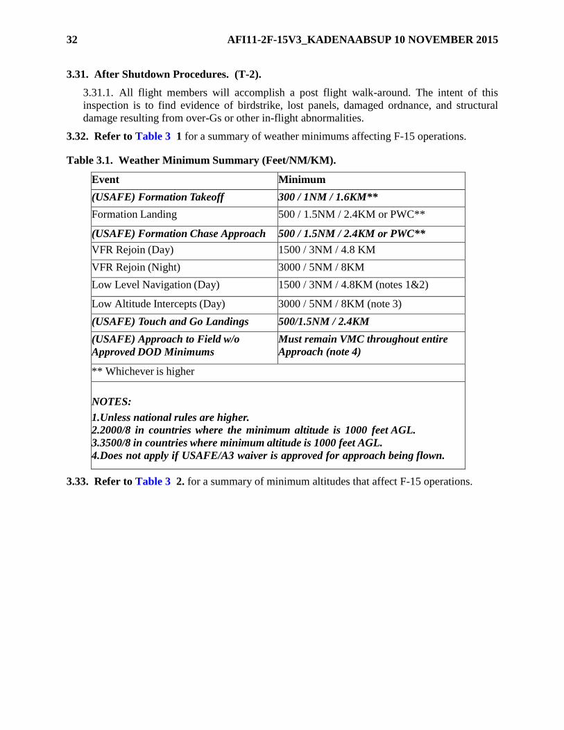
32 AFI11-2F-15V3_KADENAABSUP 10 NOVEMBER 2015
3.31. After Shutdown Procedures. (T-2).
3.31.1. All flight members will accomplish a post flight walk-around. The intent of this
inspection is to find evidence of birdstrike, lost panels, damaged ordnance, and structural
damage resulting from over-Gs or other in-flight abnormalities.
3.32. Refer to Table 3 1 for a summary of weather minimums affecting F-15 operations.
Table 3.1. Weather Minimum Summary (Feet/NM/KM).
Event Minimum
(USAFE) Formation Takeoff 300 / 1NM / 1.6KM**
Formation Landing 500 / 1.5NM / 2.4KM or PWC**
(USAFE) Formation Chase Approach 500 / 1.5NM / 2.4KM or PWC**
VFR Rejoin (Day) 1500 / 3NM / 4.8 KM
VFR Rejoin (Night) 3000 / 5NM / 8KM
Low Level Navigation (Day) 1500 / 3NM / 4.8KM (notes 1&2)
Low Altitude Intercepts (Day) 3000 / 5NM / 8KM (note 3)
(USAFE) Touch and Go Landings 500/1.5NM / 2.4KM
(USAFE) Approach to Field w/o
Approved DOD Minimums
Must remain VMC throughout entire
Approach (note 4)
** Whichever is higher
NOTES:
1.Unless national rules are higher.
2.2000/8 in countries where the minimum altitude is 1000 feet AGL.
3.3500/8 in countries where minimum altitude is 1000 feet AGL.
4.Does not apply if USAFE/A3 waiver is approved for approach being flown.
3.33. Refer to Table 3 2. for a summary of minimum altitudes that affect F-15 operations.
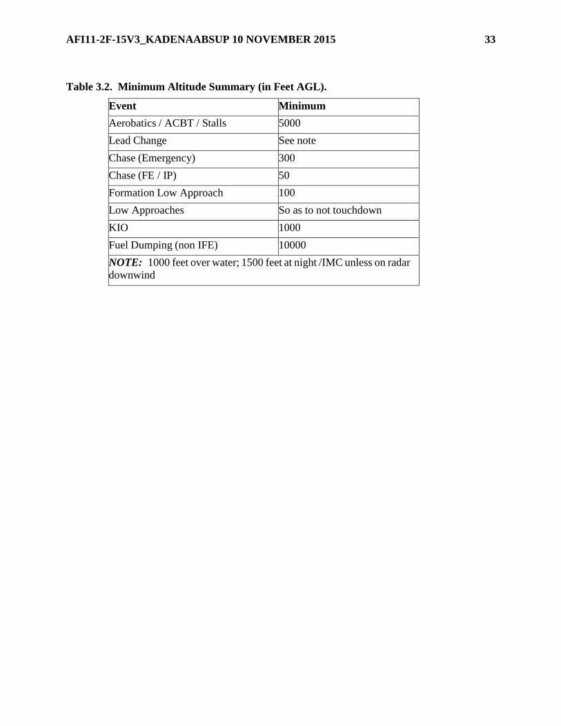
AFI11-2F-15V3_KADENAABSUP 10 NOVEMBER 2015 33
Table 3.2. Minimum Altitude Summary (in Feet AGL).
Event Minimum
Aerobatics / ACBT / Stalls 5000
Lead Change See note
Chase (Emergency) 300
Chase (FE / IP) 50
Formation Low Approach 100
Low Approaches So as to not touchdown
KIO 1000
Fuel Dumping (non IFE) 10000
NOTE: 1000 feet over water; 1500 feet at night /IMC unless on radar
downwind

34 AFI11-2F-15V3_KADENAABSUP 10 NOVEMBER 2015
Chapter 4
INSTRUMENT PROCEDURES
4.1. Approach Category. (T-0).
4.1.1. The F-15 is Approach Category E. Accomplish missed approach IAW flight manual
procedures. Missed approach airspeed is 200-250 KIAS.
4.1.2. Use approach Category D minimums at an emergency/divert airfield where no
Category E minimums are published. Airfields with Category D minimums may be
designated as an alternate (divert) airfield. Further, practice instrument approaches may be
flown using Category D minimums if VMC can be maintained throughout the procedure.
Under these circumstances, approach Category D minimums may be used provided:
4.1.2.1. A straight-in approach is flown.
4.1.2.2. The aircraft is flown at final approach airspeed of 165 KIAS or less.
4.1.2.3. The aircraft is flown at 255 knots true airspeed (KTAS) or less for the missed
approach segment of the approach. At high-pressure altitudes and temperatures 255
KTAS may not be compatible with published missed approach airspeeds and Category D
approaches should not be flown.
4.1.3. The F-15’s EGI is approved for enroute Area Navigation (RNAV). Do not fly RNAV
approaches.
4.1.4. Due to a variety of host nation and International Civil Aviation Organization (ICAO)
procedures which may differ from standard F-15 procedures, pilots must ensure that the
airspeeds they plan to fly on instrument approach procedures are compatible with both
ICAO/Terminal Instrument Procedures (TERPS) and safety of flight requirements.
4.2. Takeoff and Join-up. (T-2).
4.2.1. The flight leader must get an appropriate ATC clearance (altitude block or trail
formation) when a flight join-up is not possible due to weather conditions or operational
requirements. Formation trail departures must comply with instructions for a nonstandard
formation flight as defined in FLIP.
4.2.2. If weather is below 1500 feet and 3 miles, each aircraft/element will climb on takeoff
heading to 1,000 feet AGL before initiating any turns, except when departure instructions
specifically preclude compliance.
4.3. Trail Procedures. (T-2).
4.3.1. General.
4.3.1.1. During trail formations, basic instrument flying is the first priority and must not
be sacrificed when performing secondary trail tasks. Strictly adhere to the briefed
airspeeds, power settings, altitudes, headings, and turn points. If task saturation occurs,
cease attempts to maintain trail, concentrate on flying the instrument departure, and then
notify the flight lead. The flight lead will then notify air traffic control (ATC).
4.3.1.2. Flight leaders will request non-standard formation from ATC.

AFI11-2F-15V3_KADENAABSUP 10 NOVEMBER 2015 35
4.3.1.3. ATC instructions issued to the lead aircraft apply to the entire flight.
4.3.1.4. Flight leads will brief aircraft/element spacing. Minimum spacing between
aircraft when in non-standard formation is 9,000 feet and will be maintained using on
board radar systems.
4.3.1.5. Each aircraft/element will follow the No Radar Contact procedures until the
aircraft/element immediately in trail has radar contact and called “tied.”
4.3.2. No Radar Contact.
4.3.2.1. The flight leader will call initiating all turns. Subsequent aircraft must delay
turns to maintain the desired spacing.
4.3.2.2. Each aircraft/element will maintain 20 seconds or 2-3 mile spacing using all
available aircraft systems and navigational aids to monitor position.
4.3.2.3. During climbs and descents, each aircraft/element will call passing each 5,000
foot altitude increment with altitude and heading (or heading passing) until join-up, level-
off, or the following aircraft/element calls “tied.”
4.3.2.4. Each aircraft/element will call initiating any altitude or heading change.
Acknowledgments are not required; however, it is imperative that preceding
aircraft/elements monitor the radio transmissions and progress of the succeeding
aircraft/elements and immediately correct deviations from the planned route.
4.3.2.5. Each aircraft/element will maintain at least 1,000 feet vertical separation from
the preceding aircraft/element until establishing radar/visual contact, except in instances
where departure instructions specifically preclude compliance. Reduce vertical separation
to 500 feet if necessary to comply with MSA restrictions.
4.3.2.6. In the event a visual join-up cannot be accomplished on top or at level off, the
flight leader will request altitude separation for each succeeding aircraft/element to meet
the requirements of the above paragraph.
4.3.3. Radar Contact.
4.3.3.1. Each aircraft/element will call “tied” when radar contact is established with the
preceding aircraft. Once all aircraft are tied, no further radio calls are required, unless
radar contact is lost. If ATC directs a question, or guidance to a certain aircraft, that pilot
may respond directly to ATC. Flight leads will ensure that wingman are aware of any
unplanned or ATC directed intermediate level off altitudes.
4.3.3.2. In flights of three or more aircraft, use all available aircraft systems (i.e., radar,
TACAN, AAI, FDL, etc.) to ensure that trail is maintained on the correct aircraft.
4.3.4. Trail Departures.
4.3.4.1. Use a minimum of 20 seconds takeoff spacing.
4.3.4.2. Each aircraft/element will accelerate in MIL/AB power until reaching 350
KIAS. Climb at 350 KIAS until reaching cruise mach/KTAS, unless otherwise briefed.
4.3.4.3. Upon reaching 350 KIAS, the flight leader will set 850 FTIT unless otherwise
briefed.

36 AFI11-2F-15V3_KADENAABSUP 10 NOVEMBER 2015
4.3.4.4. Limit all turns to a maximum of 30 degrees of bank.
4.3.5. Enroute Trail. Flight leads must brief airspeeds, power settings, and configurations.
4.3.6. Trail Recovery.
4.3.6.1. Trail recovery procedures must be coordinated/approved through the responsible
ATC facilities and addressed in a local operating procedure or in the unit supplement to
this volume. Trail recoveries will only be accomplished at home stations/deployed
locations where procedures have been established and briefed. As a minimum,
procedures must address each recovery profile, missed approach, climbout, lost contact,
lost communications and desired/maximum spacing requirements.
4.3.6.1.1. [PACAF] Trail recoveries greater than a 2 ship are not authorized for any
arrival at a deployed base other than the pilots’ home station.
4.3.6.2. Limit trail recovery to a maximum of four aircraft.
4.3.6.3. Trail recoveries are authorized when weather at the base of intended landing is
at/above the highest pilot weather category in the flight or approach minimums,
whichever is higher.
4.3.6.4. Trail recoveries will not terminate in simultaneous Precision Approach Radar
(PAR) or Airport Surveillance Radar (ASR) approaches. Recoveries to separate
PAR/ASRs are authorized, flights will split prior to PAR/ASR final.
4.3.6.5. The flight lead must brief the flight on spacing, configuration, and airspeeds.
Minimum spacing between aircraft is 9,000 feet in IMC and will be maintained using on-
board radar.
4.3.6.6. The flight lead must coordinate the trail recovery with ATC prior to taking
spacing.
4.3.6.7. Prior to split-up, the flight lead must ensure that all wingmen have operative
navigational aids and air-to-air radar.
4.3.6.8. Formation break-up will be accomplished IAW paragraph 4.4 Flight
separation will be IAW local ATC directives.
4.3.6.9. The formation must squawk as directed by ATC.
4.3.6.10. ATC instructions to the lead aircraft will be for the entire flight. ATC will
provide radar flight following for the entire formation.
4.3.6.11. Limit all turns to a maximum of 30 degrees of bank.
4.3.6.12. Once established on a segment of a published approach, each aircraft must
comply with all published altitudes and restrictions while maintaining in-trail separation.
4.3.6.13. Unless local procedures establish defined reference points for airspeed/
configuration changes, the flight lead must direct changes by radio. At flight lead’s call,
all aircraft must simultaneously comply with the directed change.
4.3.6.14. All aircraft must report the final approach fix.
4.3.6.15. If contact is lost with the preceding aircraft, the pilot will transmit “Call Sign
(C/S) lost contact.” The preceding aircraft will respond with altitude, airspeed and
AFI11-2F-15V3_KADENAABSUP 10 NOVEMBER 2015 37
heading. Establish altitude deconfliction and coordinate a separate clearance with ATC. If
contact is lost while established on a segment of a published approach, flight members
may continue the approach, but must confirm separation via navigation aids. If separation
cannot be confirmed, execute missed approach or climbout as instructed by ATC.
4.4. Formation Break-up. (T-2).
4.4.1. If possible, accomplish formation break-up in VMC. If IMC, accomplish the break-up
in straight and level flight. Prior to a break-up in IMC, the flight leader must transmit
attitude, airspeed, altitude, and altimeter setting that will be acknowledged by wingmen.
Wingmen must confirm good navigational aids.
4.5. Formation Penetration. (T-2).
4.5.1. Restrict formation penetrations in route/close formation to two aircraft when the
weather at the base of intended landing is less than overhead traffic pattern minimums.
4.5.2. If a formation landing is intended, position the wingman on the appropriate wing prior
to weather penetration.
4.5.3. Formation penetrations using radar trail procedures are authorized when weather at the
base of intended landing is at/above the highest pilot weather category in the flight or
approach minimums, whichever is higher.
4.6. Formation Approach. (T-2).
4.6.1. During IMC formation flights, do not change lead or wing positions below 1,500 feet
AGL unless on RADAR downwind.
4.7. Simulated Instrument Flight. (T-2).
4.7.1. Simulated instrument flight requires a qualified safety observer in either cockpit of the
aircraft or in a chase aircraft. Use all means to clear the area for hazards.
4.7.1.1. A safety observer in the same aircraft must have an operable intercom.
4.7.1.2. A chase aircraft is required in order to log simulated instrument flight in an F-
15A/C. This does not preclude flying approaches in VMC without a chase, however, in
this case place primary emphasis on the “See and Avoid” concept. Chase aircraft will be
in a position where they can effectively clear and/or provide assistance. Chased
instrument approaches may terminate in formation landings.
4.8. Use of the Heads Up Display (HUD). (T-2).
4.8.1. For the F-15A/B/C/D, use the HUD as an additional instrument reference not as the
sole instrument reference. Do not use the HUD to recover from an unusual attitude except
when no other reference is available.
4.9. Use of the Joint Helmet Mounted Cueing System (JHMCS). (T-2).
4.9.1. Although JHMCS displays sufficient aircraft flight symbology to provide basic
situational awareness, it is not intended to be used for primary flight instrumentation. Do not
use JHMCS to recover from an unusual attitude.

38 AFI11-2F-15V3_KADENAABSUP 10 NOVEMBER 2015
Chapter 5
AIR-TO-AIR WEAPONS EMPLOYMENT
5.1. References. (T-2).
5.1.1. AFI 11-214 contains air-to-air procedures, to include operations with live ordnance
applicable to all aircraft. This chapter specifies procedures or restrictions applicable to F-15
operations.
5.2. Simulated Gun Employment. (T-2).
5.2.1. Missions may be flown with a loaded gun provided the gun is safe IAW Technical
Order (T.O.) 1F-15C-34-1-3CL-1 and a trigger check is first performed with the master arm
switch in arm with Training Mode deselected. Point the aircraft away from other aircraft and
inhabited areas during the trigger check. Do not perform a trigger check with a hot gun. If an
aircraft is flown with a hot gun or live missiles, the procedures in AFI 11-214 apply.
5.3. Maneuvering Limitations. (T-2).
5.3.1. Minimum airspeed during low altitude offensive or defensive maneuvering (LOWAT)
is 350 KIAS.
5.3.2. When configured with three external fuel tanks, aircraft will operate under the
LIMITED maneuvering category as defined in AFI 11-214. When configured with external
wing tanks and no centerline tank, UNLIMITED maneuvering is allowed once the externals
are empty (flight manual restrictions still apply). The tank restriction does not apply to aerial
gunnery tow aircraft. Tow aircraft may fly using any approved (for test and evaluation) or
certified (operational) configurations.
5.3.3. Negative-G gun jinks are prohibited.
5.3.4. When acting as a restricted maneuvering target for low altitude intercepts, the
minimum airspeed is 220 KIAS or 20 units AOA, whichever produces the higher airspeed.
5.4. Aerial Gunnery Tow Procedures. (T-2).
5.4.1. AFI 11-214 applies. In addition:
5.4.1.1. AGTS-36 Target Set Deployment. Deploy the target set over areas clear of
surface activity, near the range where shooting will occur. The tow will maintain 240 +/-
10 KIAS and ensure other flight members are clear during deployment. A chase aircraft
will ensure that the AGTS-36 tow reel turbine doors open for deployment and the visual
augmenter (VA) deploys properly. Any time the target set becomes unstable or flies
erratic, the chase aircraft will advise the tow to cut the target loose.
5.4.1.2. AGTS-36 Target Set Reel-In. The tow will slow to 240 +/- 10 KIAS and
initiate target set reel-in when shooting is complete. A chase will evaluate target set
stability and advise the tow of any abnormalities. Recover target sets that have been hit if
they do not exhibit abnormal flight characteristics. However, if a target set becomes
unstable or flies erratic during reel-in, it should be cut loose. Initiate reel-in over areas
clear of surface activity in anticipation of VA release. The chase will ensure the tow reel

AFI11-2F-15V3_KADENAABSUP 10 NOVEMBER 2015 39
turbine doors are closed, the target set locks into place, the VA releases and perform a
BDA on the tow after reel-in is complete.
5.4.1.3. TDU-32 A/B Banner Deployment. The Banner departs the airfield fully
deployed. Enroute to the range, chase aircraft will ensure a stable flying Banner. While in
straight and level flight, the chase pilot will also pass the direction of “Banner lean” in
clock position to the tow pilot. This will establish the best turn direction for employment.
(If Banner is flying at the 10 o’clock position; tow will turn right)
5.4.1.4. TDU-32 A/B Banner Recovery. The tow will return to the drop zone IAW
locally approved procedures for Banner release. Tower will clear the tow to the “drop
zone” and the pilot will release the Banner for recovery by the ground crew.
5.4.1.5. Abnormal Procedures.
5.4.1.5.1. VA fails to deploy. Reel the target set back in and do not use for firing.
5.4.1.5.2. VA fails to release after reel-in. The tow must recover using hung
ordnance procedures.
5.4.1.5.3. Erratic or unstable target set. In all cases where target sets exhibit
unstable or erratic flight characteristics, the target set should be cut loose. Avoid
trying to reel-in a target set that begins to become unstable/erratic, cut it free with
whatever length of cable is present at the time it begins to fly abnormally.
5.4.1.5.4. Target set shot off. Cut the remaining cable off. The cable may jam in the
tow reel if reel-in is attempted without a target set present.
5.4.1.5.5. Cutting target sets loose. Use primary and secondary cutters as the
preferred means to cut target sets loose. If this is unsuccessful, reel out the target set
until the cable/target set fall off. The next options depend on fuel availability, weather
and resources. The tow may try to burn the cable off using afterburner and high AOA
maneuvers. The target set may be drug off in the water. In this case, the chase will fly
no lower than 1000 feet AGL and the tow no lower than 400 feet AGL. If all other
means of cutting the target set loose are unsuccessful and the target set may not be
safely recovered, jettison the AGTS-36 tow reel.
5.4.1.5.6. Landing with cable remaining (no target set). The tow must recover
using hung ordnance procedures. Plan the landing to avoid damage to runway
approach lighting.
5.4.1.5.7. Controlled Jettison of Banner on Takeoff. If circumstances permit, tow
aircraft jettisons Banner IAW local jettison procedures.
5.4.1.5.8. Unable to Release Banner. If possible, gain chase aircraft (shooter
desired) and proceed to local jettison area and attempt jettison. If Banner still
remains, recover IAW local procedures or use (Aerial Gunnery Target Set) AGTS
cable remaining procedures.
5.4.1.5.9. Erratic/Unrecoverable Banner. Jettison in working area.
5.4.1.5.10. Banner Shot Off, Cable Remaining. Release cable in working area.
Shooter rejoins with tow to ensure no cable remains. If cable remains, follow
procedures in 5.4.1.5.6

40 AFI11-2F-15V3_KADENAABSUP 10 NOVEMBER 2015
5.5. NORAD VID Procedures. (T-2).
5.5.1. Turn the HUD camera/Digital Video Recorder (DVR) on during active air defense
visual identification passes no later than 1 NM in the target’s stern and leave it on until after
completing the breakaway maneuver.
AFI11-2F-15V3_KADENAABSUP 10 NOVEMBER 2015 41
Chapter 6
AIR-TO-SURFACE WEAPONS EMPLOYMENT
6.1. References.
6.1.1. AFI 11-214, Air Operations Rules and Procedures, contains Air-to-Surface
procedures and restrictions applicable to all aircraft. This chapter contains procedures and
restrictions specific to F-15 operations.
6.1.2. Air-to-Surface weapons employment includes both live and simulated attacks during
High Angle Strafe (HAS), Basic Surface Attack (BSA) and Maritime Air Support (MAS)
missions including A/G weapons employment against maritime targets.
6.2. Weapons Delivery Parameters. (T-2).
6.2.1. The following parameters and requirements form the basic framework for weapons
delivery training and all deliveries will conform to limits established for each specific event.
6.2.1.1. Gunnery Events. Procedures, training rules, and foul criteria are contained in
AFI 11-214. For over-land training, only preplanned target(s) will be attacked to ensure
target elevation is known and safe escape altitudes are valid.
6.2.1.1.1. High Angle Strafe.
6.2.1.1.1.1. Minimum recovery altitude is at or above pilot Low Altitude Training
(LOWAT) certified category minimums (day).
6.2.1.1.1.2. Minimum recovery altitudes are IAW AFI 11-214 Chapter 5 (night).
6.3. Simulated Attacks against Range, Off-Range or Manned Targets. (T-2).
6.3.1. May be conducted, to include use of Master Arm when carrying practice ordnance
under the following restrictions:
6.3.1.1. No live A/A missiles are loaded.
6.3.1.2. Simulated Strafe.
6.3.1.2.1. Simulated strafe is defined as the combined use of Master Arm and trigger
actuation during a practice gun attack against ground targets.
6.3.1.2.2. Simulated strafe is permitted with a safed gun, loaded or unloaded,
provided a trigger check is previously accomplished.
6.3.1.2.3. Do not perform simulated strafe with a hot gun (loaded or empty).
42 AFI11-2F-15V3_KADENAABSUP 10 NOVEMBER 2015
Chapter 7
ABNORMAL OPERATING PROCEDURES
7.1. General. (T-2).
7.1.1. Follow the procedures in this chapter when other than normal circumstances occur.
These procedures do not supersede flight manual guidance.
7.1.1.1. Do not accept an aircraft for flight with any problem that could jeopardize safe
flight.
7.1.1.2. Do not use a malfunctioning system unless it is required for safe recovery of the
aircraft. Do not continue in-flight troubleshooting a malfunction after completing flight
manual emergency procedures and the aircraft may be safely recovered.
7.1.1.3. Only conduct fuel dumping to reduce aircraft gross weight for safety of flight.
When circumstances permit, dump above 10,000 feet AGL over unpopulated areas.
Ensure the dump switch is returned to normal before landing. Make the appropriate entry
in the AFTO Form 781A, Maintenance Discrepancy and Work Document.
7.1.1.4. Do not taxi aircraft with malfunctions that effect the nosewheel steering or brake
system.
7.1.1.5. For actual or perceived flight control malfunctions, terminate maneuvering and
take appropriate action. If the flight control problem was due to crew member/passenger
stick or rudder interference in B/D model aircraft, the pilot will take appropriate action to
ensure no further flight control interference occurs.
7.2. Ground Aborts. (T-2).
7.2.1. If a flight member aborts prior to takeoff, the flight leader will normally renumber the
flight. Flight leaders must advise the appropriate agencies of such changes.
7.2.2. In the event of an abort, formation flight may only continue if it is led by a qualified
flight lead. The alternatives are a sympathetic abort or proceeding on a pre-briefed single-
ship mission.
7.2.3. Delayed aircraft may join the flight at a briefed rendezvous point or may fly a briefed
alternate single ship mission. If accomplishing a join-up, cease tactical maneuvering until the
delayed aircraft is joined and all flight members are ready to continue.
7.3. Takeoff Aborts. (T-2).
7.3.1. If aborting the takeoff, clear to the appropriate side of the runway as expeditiously as
possible based on position within the element. If this is not feasible because of possible cable
engagement, clear straight-ahead. As soon as practical, give callsign and state intentions. Call
“Cable, Cable, Cable” to indicate a departure-end arrestment. Following aircraft hold their
position, abort or takeoff as appropriate to maintain adequate clearance.
7.3.2. IAW T.O. 1F-15A-1, consideration should be given to hot brakes when brakes are
applied above 100 KIAS. Ground speed, runway length, gross-weight, runway condition,
heavy braking and outside air temperature are all variable factors which could contribute to

AFI11-2F-15V3_KADENAABSUP 10 NOVEMBER 2015 43
hot brakes. If hot brakes are suspected; declare a ground emergency, taxi the aircraft to the
designated hot brake area, and follow hot brake procedures.
7.3.3. If aborting a takeoff at or above 100 KIAS, lower the tailhook. If aborting below 100
KIAS, lower the tailhook if there is any doubt about the ability to stop on the runway.
7.3.4. Following an aborted takeoff, consider having ground maintenance personnel check
the aircraft for hot brakes prior to attempting a subsequent takeoff in the same aircraft.
7.4. Air Aborts. (T-2).
7.4.1. If an abort occurs after takeoff, all aircraft will maintain their original numerical
callsign.
7.4.2. Escort aborting aircraft with an emergency to the field of intended landing. In other
cases, the flight leader will determine if an escort is required.
7.4.3. Abort the mission and land out of a straight-in approach, regardless of apparent
damage or subsequent normal operation, for any of the following:
7.4.3.1. Birdstrike/Foreign Object Damage.
7.4.3.2. Flight control system anomalies. This does not include flight control system
lights that reset IAW flight manual procedures.
7.4.3.3. Engine flameout, stagnation or shutdown.
7.4.4. If an aircraft experiences an over-G, use the following procedures:
7.4.4.1. Perform a battle damage check after all over-Gs.
7.4.4.2. Non-OWS equipped aircraft and OWS equipped aircraft whose OWS is not
operational.
7.4.4.2.1. Terminate the mission and land as soon as practical from a straight-in
approach.
7.4.4.3. Aircraft equipped with an operable OWS system that experiences an over-G.
7.4.4.3.1. Immediately terminate maneuvering and call up the OWS matrix on the
VSD to analyze the displayed parameters.
7.4.4.3.2. If a positive G, level “1” (one) is displayed in any column of the matrix
except mass items (MIT), perform a battle damage check with emphasis on the
overall condition of the aircraft. If no abnormalities are noted, the flight lead may
continue the briefed mission. If a subsequent positive G, level “1” or greater over-G
occurs, terminate the mission, perform a battle damage check, RTB and fly a straight-
in approach, except as noted below.
7.4.4.3.3. If level “1” (positive or negative) or greater is displayed in the MIT
column, terminate the mission, perform a battle damage check, RTB and fly a
straight-in approach.
7.4.4.3.4. If a positive G, level “2” (two) or greater; or a negative G, any level, is
displayed in any column of the matrix, terminate the mission, perform a battle
damage check, RTB and fly a straight-in approach.

44 AFI11-2F-15V3_KADENAABSUP 10 NOVEMBER 2015
7.4.4.4. Document actual over-Gs (positive G, level 1 or greater, or negative G, any
level) in the AFTO Form 781A, Maintenance Discrepancy and Work Document after
flight.
7.4.5. In the F-15B/D, the pilot in command is primarily responsible for handling in-flight
emergencies. The additional aircrew member will provide checklist assistance at the request
of the pilot in command.
7.5. Engine Malfunctions. (T-2).
7.5.1. Report all engine anomalies during maintenance debriefing.
7.6. Radio Failure. (T-2).
7.6.1. General. Individual aircraft experiencing radio failure will comply with procedures
outlined in FLIP, AFI 11-202 Volume 3, this instruction, and local directives.
7.6.2. Formation:
7.6.2.1. Flight members who experience total radio failure while in close or route
formation will maneuver within close/route parameters to attract the attention of another
flight member and give the appropriate visual signals. Terminate the mission as soon as
practical and lead the NORDO aircraft to the base of intended landing or a divert base.
Perform a formation approach to a drop-off on final unless safety considerations dictate
otherwise.
7.6.2.2. If flying other than close/route formation when radio failure occurs, the NORDO
aircraft should attempt to rejoin to a route position at approximately 500 feet on another
flight member. The NORDO aircraft is responsible for maintaining clearances from other
flight members until his presence is acknowledged by a wingrock, signifying clearance to
join. Once joined, the NORDO aircraft will give the appropriate visual signals. If pre-
briefed, the NORDO aircraft may proceed to a rendezvous point and hold. If no one has
rejoined prior to reaching BINGO fuel, the NORDO aircraft should proceed to the base
of intended landing or a divert base. Aircraft experiencing any difficulty/emergency in
addition to NORDO will proceed as required by the situation.
7.6.3. Aerial Gunnery/Air-to-Surface Gunnery/Missile Firing NORDO Procedures:
7.6.3.1. Aircraft will not fire without two-way radio contact.
7.6.3.2. Shooting aircraft: safe the armament switches, join on another member of the
flight or the tow aircraft, IAW paragraph 7.6.2
7.6.3.3. Aerial gunnery tow aircraft: rocks wings and continue the turn if an attack is in
progress. The flight leader of the attacking aircraft will “knock off” the attack and join on
the tow’s wing, remaining clear of the target in the event it is cut. The tow pilot will use
standard hand signals to indicate his difficulty. The flight leader will signal when the
target is cleared for cut with a slicing motion across the throat. After the target is away
and the flight lead determines there is no remaining cable, the tow will RTB with an
escort following the briefed NORDO recovery procedures. If cable remains, follow local
procedures.

AFI11-2F-15V3_KADENAABSUP 10 NOVEMBER 2015 45
7.6.4. NORDO Recovery:
7.6.4.1. Apply the procedures in AFI 11-205 and FLIP.
7.6.4.2. If a formation straight-in approach is flown and a go-around becomes necessary,
the chase will go-around, pass the NORDO aircraft and rock his wings. The NORDO
aircraft will go-around, if the situation allows. If the NORDO aircraft is in formation as a
wingman, the leader will initiate a gentle turn into the wingman and begin the go-around.
7.6.4.3. A NORDO aircraft intending to make an approach-end cable engagement should
signal the escorting aircraft by extending the tailhook. If the NORDO aircraft is not
escorted, the pilot should fly a straight-in approach flashing the landing light on final to
signal the tower.
7.7. Severe Weather Penetration. (T-2).
7.7.1. Avoid flight through severe weather. If unavoidable, flights should break-up and
obtain separate clearances prior to severe weather penetration.
7.8. Lost Wingman Procedures. (T-2).
7.8.1. In any lost wingman situation, immediate separation of aircraft is essential. Upon
losing sight of the leader or if unable to maintain formation, the wingman will
simultaneously:
7.8.1.1. Execute the applicable lost wingman procedures. Refer to para 7.9 for specific
spatial disorientation (SD) considerations. Smooth application of control inputs is
imperative to minimize the effects of SD.
7.8.1.1.1. Transition to primary flight instruments.
7.8.1.1.2. Inform lead by transmitting “C/S is lost wingman.”
7.8.1.1.3. After executing a lost wingman procedure, do not attempt rejoining with
the flight until obtaining permission from the flight lead.
7.8.1.1.4. When able, obtain a separate clearance.
7.8.1.1.5. Observe all published terrain clearance limits.
7.8.1.2. Two- or Three-Ship Flights (three-ship echelon, refer to four-ship
procedures):
7.8.1.2.1. Wings-level flight (climbing, descending, or straight and level). Turn
away using 15 degrees of bank for 15 seconds, then resume original heading.
7.8.1.2.2. Turns:
7.8.1.2.2.1. Outside the Turn. Reverse the direction of turn using 15 degrees of
bank for 15 seconds. Continue straight ahead to ensure separation prior to
resuming the turn.
7.8.1.2.2.2. Inside the Turn. Momentarily reduce power to ensure nose-tail
separation and direct the flight leader to roll out of the turn. Maintain the original
turn. The leader may only resume the turn when separation is ensured.

46 AFI11-2F-15V3_KADENAABSUP 10 NOVEMBER 2015
7.8.1.2.3. Final Approach. Momentarily turn away from lead to ensure clearance
and execute the published missed approach procedure.
7.8.1.2.4. Missed Approach. Momentarily turn away from lead to ensure clearance
and continue the published or assigned missed approach procedure. Climb to 500 feet
above missed approach altitude.
7.8.1.3. Four-Ship Flights. Number 2 and 3 follow the procedures outlined above.
Number 4’s initial action assumes that number 3 has also gone lost wingman. In addition
to paragraph 7.8 number 4 will:
7.8.1.3.1. Wings-Level Flight (climbing, descending, or straight and level). Turn
away using 30 degrees of bank for 30 seconds, then resume the original heading.
7.8.1.3.2. Turns:
7.8.1.3.2.1. Outside the Turn. Reverse direction of turn using 30 degrees of
bank for 30 seconds to ensure separation from lead and number 3.
7.8.1.3.2.2. Inside the Turn. Momentarily reduce power to ensure nose-tail
separation and increase bank angle by 15 degrees. Direct the leader to roll out.
The leader will only resume the turn when separation is ensured.
7.8.1.4. Leader must acknowledge the lost wingman’s radio call and, when appropriate,
transmit attitude, heading, altitude, airspeed, and other parameters.
7.8.1.5. If a wingman becomes separated and any aircraft experiences radio failure, the
aircraft with the operational radio will obtain a separate clearance. The NORDO aircraft
will turn the IFF/SIF to NORMAL code 7600 while proceeding with previous clearance.
If an emergency situation arises along with radio failure, turn the IFF/SIF to
EMERGENCY for the remainder of the flight.
7.8.1.6. Only practice lost wingman procedures in VMC.
7.9. Spatial Disorientation (SD). (T-2).
7.9.1. Conditions that prevent a clear visual horizon or increase pilot tasking are conducive
to SD. To prevent SD, the pilot must increase his instrument crosscheck rate. If SD
symptoms are encountered:
7.9.1.1. Single Ship:
7.9.1.1.1. Concentrate on flying basic instruments with frequent reference to the
attitude indicator. Use heads-down instruments. If flying dual, consider transferring
control to the other crewmember.
7.9.1.1.2. If symptoms persist and conditions permit, fly straight and level flight until
symptoms abate, usually within 60 seconds. Consider using the autopilot.
7.9.1.1.3. If necessary, declare an emergency and advise ATC.
7.9.1.1.4. Note: It is possible for SD to proceed to the point where the aircrew is
unable to see or interpret the flight instruments. In this situation, aircraft control may
be impossible. If this occurs, the aircrew should consider ejecting.
7.9.1.2. Formation Lead:
AFI11-2F-15V3_KADENAABSUP 10 NOVEMBER 2015 47
7.9.1.2.1. Advise the wingmen that he has SD and comply with procedures in
paragraph 7.9.1.1
7.9.1.2.2. Use the wingmen to confirm attitude and provide verbal feedback.
7.9.1.2.3. If symptoms persist, terminate the mission and recover the flight by the
simplest and safest means possible.
7.9.1.3. Formation Wingman:
7.9.1.3.1. Advise lead of the disorientation.
7.9.1.3.2. Lead will advise wingman of aircraft attitude, altitude, heading, and
airspeed.
7.9.1.3.3. If symptoms persist and conditions permit, lead will establish straight and
level flight for 30-60 seconds
7.9.1.3.4. If the above procedures are not effective, lead should consider passing the
lead to the wingman, provided the leader will be able to maintain situational
awareness from a chase position. Transfer lead while in straight and level flight. Once
assuming the lead, maintain straight and level flight for 60 seconds. If necessary,
terminate the tactical mission and recover by the simplest and safest means possible.
7.9.1.4. Greater than 2-Ship Formation. Lead should separate the flight into elements
to more effectively handle a wingman with persistent SD symptoms. Establish straight
and level flight IAW paragraph 4.4 (Formation Break-up). Plan to keep the element
with the SD pilot straight and level while the other element separates.
7.10. Armament System Malfunctions. (T-2).
7.10.1. Inadvertent Release.
7.10.1.1. Record switch positions at the time of inadvertent release and provide to
armament and safety personnel. Record the impact point, if known.
7.10.1.2. Safe the armament switches and do not attempt further release in any mode.
Treat remaining stores as hung ordnance and follow hung ordnance procedures during
RTB.
7.10.1.3. If remaining stores present a recovery hazard, jettison them in a suitable area on
a single pass, if practical.
7.10.2. Failure to Release/Hung Ordnance. If ordnance fails to release when all
appropriate switches are set, proceed as follows.
7.10.2.1. Hung live ordnance or aircraft malfunction that precludes further live weapons
delivery.
7.10.2.1.1. Attempt to release store(s) using an alternate delivery mode. (Not
Applicable [N/A] for Air-to-Air WSEP.) If unsuccessful, attempt to jettison store(s)
using selective jettison procedures. Lastly, consider attempting to selectively jettison
the pylon if ordnance is unsecured or security cannot be determined.
7.10.2.1.2. If ordnance remains on the aircraft, follow the hung ordnance recovery
procedures in paragraph 7.10.4.

48 AFI11-2F-15V3_KADENAABSUP 10 NOVEMBER 2015
7.10.3. Hangfire/Misfire:
7.10.3.1. A missile that fires but fails to depart the aircraft is a hangfire. If this occurs,
the missile should be closely observed and safety checked by a chase pilot.
7.10.3.2. A missile that fails to fire when all appropriate switches were selected is a
misfire. If this occurs, safe the Master Arm switch and follow the hung ordnance
recovery procedures.
7.10.4. Hung Ordnance/Weapons Malfunction Recovery:
7.10.4.1. If practical, visually inspect the aircraft for damage.
7.10.4.2. Declare an emergency for hung live ordnance (not required for hung
practice/inert ordnance or for live unexpended ordnance).
7.10.4.3. If available, obtain a chase aircraft (N/A at night) and avoid populated areas
and trail formations.
7.10.4.4. Land from a straight-in approach.
7.10.5. Miscellaneous Procedures:
7.10.5.1. Pilots will not attempt to expend ordnance using a delivery system with a
known weapons release malfunction.
7.10.5.2. When abnormal missile launch or erratic missile flight is noted after launch,
visually inspect the launching aircraft by another pilot (if possible) to determine if any
damage has occurred.
7.11. Post Arresting Gear Engagement Procedures. (T-2).
7.11.1. Do not shut down the engine(s) unless directed by the ground crew, there is a fire, or
other conditions dictate.
7.11.2. Raise the tailhook on the ground crew’s signal.
7.11.3. Do not taxi until directed.
7.11.4. Comply with local directives.
7.12. In-flight Practice of Emergency Procedures. (T-2).
7.12.1. Simulated Emergency Procedure is defined as any procedure that produces an effect
that closely parallels an actual emergency, such as retarding the throttle to simulate the drag
equivalent to a flamed out engine.
7.12.2. Aborted Takeoff Practice. Only practice aborted takeoffs in the flight simulator,
Cockpit Procedures Trainer (CPT), or, if the trainer is unavailable, a static aircraft.
7.12.3. Simulated in-flight loss of both engines is prohibited.
7.12.4. Practice in-flight engine shutdown is prohibited.
7.12.5. Emergency Landing Patterns (Refer to AFI 11-202 Volume 3).
7.12.5.1. Field Requirements. Practice of emergency landing patterns at active airfields
is authorized provided that crash rescue and air traffic control facilities are available and
in operation.

AFI11-2F-15V3_KADENAABSUP 10 NOVEMBER 2015 49
7.12.5.2. Supervisory Requirements. IQT (including Formal Training Unit [FTU])
pilots require an IP on board the aircraft or in a chase aircraft. MQT (including FTU)
pilots require a SOF in place and an IP or flight lead monitoring from the traffic pattern.
7.12.5.3. Pattern Procedures:
7.12.5.3.1. Include the type of practice emergency pattern in the gear check call.
7.12.5.3.2. Initiate practice single-engine go-arounds in sufficient time to ensure the
aircraft does not descend below 300 feet AGL. Simulated single-engine approaches
may descend below 300 feet AGL provided the approach terminates in a full stop
landing or the go-around from a low approach or touch and go landing is performed
with both engines. When conducting such training, the pilot will advise the
appropriate air traffic controller of his intentions.
7.13. Search and Rescue (SARCAP) Procedures. (T-2).
7.13.1. If an aircraft crashes, immediately attempt to locate possible survivors and initiate
rescue efforts. Expect that the aircrews may initially suffer from shock or have delayed
reactions due to ejection injuries. The following procedures are by no means complete and
should be adjusted to meet each unique search and rescue situation.
7.13.1.1. Knock off maneuvering.
7.13.1.2. Establish a SARCAP commander.
7.13.1.3. Squawk 7700 to alert ATC/Ground Controlled Intercept (GCI) of the
emergency situation.
7.13.1.4. Communicate the emergency situation and aircraft/flight intentions
immediately to applicable control agencies. Use GUARD frequency if necessary.
7.13.1.5. Mark the last known position of survivors/crash site using any means available
(TACAN, EGI, FDL, ATC/GCI position and/or visual references).
7.13.1.6. Remain above the highest ejection altitude, if known, or the highest observed
parachute until determining the position of all possible survivors.
7.13.1.7. Deconflict other aircraft assisting in the SARCAP by altitude to preclude
midair collision. Establish high/low Combat Air Patrol (CAP) as necessary to facilitate
communications.
7.13.1.8. Revise BINGO fuels or recovery bases as required to maintain maximum
SARCAP coverage. Do not overfly the adjusted BINGO fuel.
7.13.1.9. Relinquish SARCAP operation to designated rescue forces upon their arrival.
7.13.1.10. Follow local or briefed procedures.
7.14. Lateral Asymmetry. (T-2).
7.14.1. When a fuel imbalance develops that exceeds 5000 ft/lbs. of lateral asymmetry,
terminate maneuvering and investigate. If the imbalance was caused by a slow feeding
external or internal wing tank, restrict maneuvering to instruments, deployment missions, or
limited maneuvering intercepts less than 30 units AOA, IAW tech order guidance, until the
imbalance is corrected. Pilots will use the High AOA Warning Tone as a tool to limit the

50 AFI11-2F-15V3_KADENAABSUP 10 NOVEMBER 2015
aircraft to less than 30 units. If the imbalance cannot be corrected, terminate the mission. The
above events can be flown to reduce gross weight.
7.14.2. Weapon and stores asymmetry must also be included to compute the total asymmetry
condition.
7.14.3. Use the following rules of thumb in Table 7.1 to determine if a fuel asymmetry
condition exceeds the Dash-1 limit of 5000 ft/lbs:
Table 7.1. Asymmetry ROTs.
Location of Fuel To get total ft/pounds:
Internal Wing Fuel 8 X imbalance = (ft/pounds)
External Wing Fuel 10 X imbalance = (ft/pounds)

AFI11-2F-15V3_KADENAABSUP 10 NOVEMBER 2015 51
Chapter 8
LOCAL OPERATING PROCEDURES
8.1. This chapter is reserved for unit local operating procedures. (T-2).
8.1.1. Procedures herein will not be less restrictive than those contained elsewhere in this
instruction. This chapter is not intended to be a single source document for procedures
contained in other directives or regulations. Avoid unnecessary repetition of guidance
provided in other established directives; however, reference to those directives is acceptable
when it serves to facilitate location of information necessary for local operating procedures.
Each pilot is authorized a copy of this chapter. MAJCOMs or other subordinate agencies
(Numbered Air Force [NAF], Center, etc.), may direct publications approval channels and a
specific format for Chapter 8 based on unique flying areas, missions, and/or procedures.
Unless changed by MAJCOM or subordinate agency, the following procedures apply.
8.1.1.1. When published, units will forward copies to MAJCOM and appropriate
subordinate agencies, who will review the Chapter 8 and return comments or required
changes back to the unit(s), if appropriate. The process need not delay distribution unless
specified otherwise by MAJCOM or a subordinate agency. If a procedure is applicable to
all F-15 A-D units, it will be incorporated into the basic instruction.
8.1.1.1.1. Organize the local chapter in the following format and, as a minimum,
include the following:
8.1.1.1.1.1. Section A. Introduction.
8.1.1.1.1.2. Section B. General Policy.
8.1.1.1.1.3. Section C. Ground Operations.
8.1.1.1.1.4. Section D. Flying Operations.
8.1.1.1.1.5. Section E. Weapons Employment.
8.1.1.1.1.6. Section F. Abnormal Procedures.
8.1.1.1.1.7. Attachments. (Illustrations)
8.1.1.1.2. Include procedures for the following, if applicable:
8.1.1.1.2.1. Command and Control.
8.1.1.1.2.2. Fuel Requirements and Bingo Fuels.
8.1.1.1.2.3. Diversion Instructions.
8.1.1.1.2.4. Jettison Areas/Procedures/Parameters (IFR/VFR).
8.1.1.1.2.5. Controlled Bailout Areas.
8.1.1.1.2.6. Local Weather Procedures.
8.1.1.1.2.7. Unit Standards (Optional).
8.1.1.1.2.8. Approved Alternate Missions.

52 AFI11-2F-15V3_KADENAABSUP 10 NOVEMBER 2015
8.1.1.1.2.9. Cross-Country Procedures (if applicable).
8.1.1.1.2.10. Search and Rescue (SARCAP) Procedures.
8.1.1.1.2.11. Local Environmental Restrictions to Flight Operations (winds, sea
state, temperature, etc.) as applicable to unit locations.
AFI11-2F-15V3_KADENAABSUP 10 NOVEMBER 2015 53
Chapter 8 (KADENAAB)
LOCAL OPERATING PROCEDURES
Section 8A (KADENAAB)—Introduction
8.1. (KADENAAB) Scope. This supplement establishes local operating procedures for Kadena
AB and supplements the basic instruction. It applies to pilots who fly 18th Operations Group (18
OG) F-15s. Most information is specific to Kadena AB. However, when deployed to other
locations, comply with this supplement to the maximum extent possible, or local guidance,
whichever is more restrictive.
8.2. (Added-KADENAAB) Deviations. The 18th Operations Group Commander (18 OG/CC)
or his designated representative may authorize deviations to local procedures specified in this
chapter.
8.3. (Added-KADENAAB) References. The primary references for F-15 operations are T.O.s
1F-15A-1, 1F-15A-1-1, 1F-15C-34-1-3, AFTTP 3-1.F-15, AFTTP 3-3.F-15, AFI 11-214, AFI
11-2F-15V3, and KABI 13-204, Airfield Operations Instruction. This supplement should be used
in conjunction with the Shogun In-flight Guide, Volume 1, F-15, and Volume 2, F-15 Exercise /
Base-X, maintained by 18 OG Standardization and Evaluation (18 OG/OGV).
8.4. (Added-KADENAAB) Changes. Submit recommendations for improvements via AF
Form 847, Recommendation for Change of Publication, to 18 OG/OGV.
Section 8B (KADENAAB)—General Policy
8.5. (Added-KADENAAB) 18 OG Standards. Standards provide a common reference for
conducting daily flying operations. Flight leads may deviate from the standards; however,
deviations must be briefed. Refer to the classified 18 OG Tactical Standards for tactical
employment and the 18 OG Admin Standards for administrative guidance.
8.6. (Added-KADENAAB) Flight-Duty Period Limitations. Pilots and supervisors of flying
(SOF) will adhere to the Flight-Duty Period (FDP) and minimum pilot rest requirements
specified in AFI 11-202, Volume 3, and its PACAF supplement.
8.6.1. (Added-KADENAAB) Fighter FDP may be extended to 14 hours for fighter aircraft
delivery missions including transoceanic (re)deployment with the 18th Wing Commander (18
WG/CC) approval as per PACAF/DO waiver.
8.6.2. (Added-KADENAAB) Pilots may fly up to three sorties per day as long as the third
sortie lands before the end of civil twilight.
8.7. (Added-KADENAAB) Go/No-Go Procedures. Pilots must be current for Flight Crew
Information Files (FCIFs), Volume I, Sections A, B, C, Safety Read File, Stan/Eval periodic
testing requirements, and Situational Emergency Procedures Training (SEPT) prior to being
assigned an aircraft.
8.8. (Added-KADENAAB) Situational Emergency Procedure Training (SEPT).
8.8.1. (Added-KADENAAB) Accomplish a SEPT each calendar month in accordance with
AFI 11-2F-15, Volume 1. Failure to accomplish by the end of the month will result in
54 AFI11-2F-15V3_KADENAABSUP 10 NOVEMBER 2015
grounding until subsequently completed. Log SEPTs on Kadena AB Form 18, Situational
Emergency Procedure Training (SEPT) Card. Maintain the current cards near the squadron
operations desk. Squadron project officers should ensure SEPT cards are taken on flying
temporary duties (TDYs).
8.8.2. (Added-KADENAAB) SEPT sessions will be accomplished in accordance with AFI
11-2F-15, Volume 1, the current Ready Aircrew Program (RAP) Tasking Message, and
individual squadron policy.
8.8.2.1. (Added-KADENAAB) Pilots will cover the SEPT Topic of the Month during
each SEPT session. 18 OG F-15 Stan/Eval (18 OG/OGV) will publish an SEPT Topic of
the Month list. This list will be included in each new reprint of the Kadena AB Form 18,
Situational Emergency Procedure Training (SEPT) Card.
8.8.2.2. (Added-KADENAAB) SEPT sessions will include at least one flight lead and
will cover at least ten emergency procedures (EPs). At least 5 of 10 EPs must be critical
EPs marked with an “*” on the SEPT card. Cover each EP at least once per half year.
Discuss situations that include weather and other factors that require pilots to work
through the decision making process to safely recover the aircraft.
8.9. (Added-KADENAAB) Publications.
8.9.1. (Added-KADENAAB) Pilots will carry the following on all flights:
8.9.1.1. (Added-KADENAAB) T.O.1F-15A-1CL-1, Flight Checklist.
8.9.1.2. (Added-KADENAAB) T.O. 1F-15C-34-1-3CL-1, Nonnuclear Weapons
Delivery Checklist.
8.9.1.3. (Added-KADENAAB) Shogun In-Flight Guide, Volume 1, F-15.
8.9.1.4. (Added-KADENAAB) Shogun Eagle Driver Supplement.
8.9.1.5. (Added-KADENAAB) Appropriate FLIP:
8.9.1.5.1. (Added-KADENAAB) En Route Supplement (with any applicable
change notices).
8.9.1.5.2. (Added-KADENAAB) Flight Information Handbook.
8.9.1.5.3. (Added-KADENAAB) Volume 1.
8.9.1.5.4. (Added-KADENAAB) Volume 2.
8.9.1.5.5. (Added-KADENAAB) En Route Charts 3, 4, 5, and 6.
8.9.1.5.6. (Added-KADENAAB) Kadena AB Form 4 (or substitute), F-15 Flight
Data, on local missions. A substitute Kadena AB Form 4, as a minimum, must
include all information on the front of the Kadena AB Form 4 including Takeoff and
Landing Data (TOLD).
8.9.2. (Added-KADENAAB) During Exercises pilots will also carry a Shogun In-Flight
Guide, Volume 2, F-15 Exercise/Base X.
8.10. (Added-KADENAAB) Life Support Equipment.

AFI11-2F-15V3_KADENAABSUP 10 NOVEMBER 2015 55
8.10.1. (Added-KADENAAB) Pilots will check their life support equipment thoroughly
prior to each flight. Oxygen and communications connections will be checked on a
compatible tester, if available.
8.10.2. (Added-KADENAAB) Select Pressure Breathing (PBG) on the aircraft oxygen
regulator for all flights.
8.10.3. (Added-KADENAAB) Pilots will wear the survival vest IAW current MAJCOM
wear policy and any applicable waivers.
8.11. (Added-KADENAAB) Command and Control.
8.11.1. (Added-KADENAAB) Aborts. If a flight member ground aborts, the flight lead
may renumber the flight as required and inform squadron operations. Squadron operations
will notify Shogun 10 of the change.
8.11.2. (Added-KADENAAB) Single-Ship Policy. Approved local single-ship missions
due to airborne fallout are advanced handling or dedicated instrument sorties. Both require
operations supervisor approval when other F-15s are airborne or squadron commander
(SQ/CC) or squadron deputy commander (SQ/DO) approval when no other F-15s are
airborne. SQ/CC, SQ/DO or designated rep approval is required for single-ship AHC sorties
by inexperienced pilots. Single-ship aircraft will attempt to utilize airspace occupied by other
F-15s to the max extent possible and establish radio contact on area common or C2. Single-
ship aircraft will also establish two-way radio contact with the SOF (Shogun 10) to include
area entry, check-in every 30 minutes, and monitor SOF frequency during RTB. Single-ship
off island cross-country flights requires 18 OG/CC or designated representative approval.
8.11.3. (Added-KADENAAB) Rescue support is coordinated by the SOF.
8.11.4. (Added-KADENAAB) Cables at MCAS Futenma. During all local single-
runway operations or anticipated dual runway closure during daily operations, the SOF will
verify the cable status at MCAS Futenma.
8.12. (Added-KADENAAB) Fuel Requirements.
8.12.1. (Added-KADENAAB) VFR Fuel Requirement. Set area bingos to arrive at the
FAF or initial with at least 2,000# (day) and 3,000# (night or single runway ops). Once
established in the local VFR or RADAR pattern, pilots will weigh AFI 11-2F-15, Volume 1,
training requirements/currencies, land times, tower crew training and pattern congestion to
continue pattern work or land, but pilots will land with at least 1,500#.
8.12.2. (Added-KADENAAB) IFR Fuel Requirement. Set area bingos (day or night) to
arrive at the FAF with at least the required alternate/divert fuel in accordance with Table 8.1
During IFR conditions, contact the SOF, as required, for the most current weather
information.

56 AFI11-2F-15V3_KADENAABSUP 10 NOVEMBER 2015
Table 8.1. (Added-KADENAAB) Fuel Required.
Airfield Status Fuel Required at FAF / Initial
Day VFR Recoveries – Either Pattern Open 2,000 #
Night VFR Recoveries or Single Runway Ops 3,000 #
IFR Recoveries – Naha/Futenma Alternate 3,000 #
IFR Recoveries – Nyutabaru Alternate 8,000 #
8.13. (Added-KADENAAB) Weather.
8.13.1. (Added-KADENAAB) Weather Conditions. The 18 OG/CC (or designated rep),
Top 3, or SOF may WX Hold takeoffs. Expect this WX Hold call to come from the SOF, in
consultation with the 18 OG/CC. Individual squadrons will make the decision to delay or
CNX flying. This decision will be from the SQ/CC or DO, and can be delegated to the Top 3.
Upon making a WX CNX call, Top 3 will notify the 18 OG/CC (or designated rep) and all
required agencies IAW WX Cancel checklist. During this notification, the Top 3 must clarify
that they are only speaking for the 44 FS or 67 FS, not all flying for the OG.
8.13.2. (Added-KADENAAB) Extreme Circumstances. The 18 OG/CC or designated
rep may decide to cancel flying for the entire wing in extreme cases. Example: An inbound
typhoon, impending contingency operation, etc.
8.13.3. (Added-KADENAAB) Local Wind Limit. Kadena F-15s will not fly training
sorties in airspace where current or forecast surface prevailing winds exceed 30 knots or
gusts above 40 knots. Local F-15 flying will be canceled if Kadena AB current or forecast
surface prevailing winds exceed 30 knots or gusts above 40 knots. Local wind limit may be
waived by the 18 OG/CC on a case by case basis.
8.13.4. (Added-KADENAAB) Local Wave Heights Limit. Due to the limited reporting
capability of accurate wave heights in the local flying area, the best information is available
on the Kadena Weather sharepoint page. The SOF, in conjunction with the 18 OG/CC or his
representative, will use the following wave height guidance to determine suitability for
fighter flying operations.
8.13.4.1. (Added-KADENAAB) Wave heights 10’ or greater: No local F-15C sorties
may be launched unless waived by the 18 OG/CC.
8.13.5. (Added-KADENAAB) On Island Alternates. MCAS Futenma should be the
primary alternate, if current or forecast weather allows.
8.13.6. (Added-KADENAAB) Fighter Index of Thermal Stress (FITS) guidance applies to
pilots outside of an air-conditioned environment. An F-15C with engines running and an
operable Environmental Control System (ECS) is considered an air-conditioned environment.
See Attachment 23 for Fighter Index of Thermal Stress chart.
8.14. (Added-KADENAAB) Bird Watch Condition.
8.14.1. (Added-KADENAAB) Reference KABI 13-204.
8.14.2. (Added-KADENAAB) Bird Watch Condition Moderate. F-15Cs loaded with full
external wing tanks will use AB for takeoff until reaching 250 knots. At 250 knots the pilot
will select military power and initiate a 250 knot climb to level off at 1000 feet MSL. Remain

AFI11-2F-15V3_KADENAABSUP 10 NOVEMBER 2015 57
below 1300 feet MSL and accelerate to climb speed until past the departure end of the
runway.
Section 8C (KADENAAB)—Ground Operations
8.15. (Added-KADENAAB) Preflight.
8.15.1. (Added-KADENAAB) Step Brief. Qualified operations supervisors will brief, at a
minimum, aircraft tail number, parking location, configuration, maintenance status, airfield
status to include significant Notice to Airmen (NOTAMs), hazards, constraints, weather,
tanker/AWACS/GCI/adversary coordination and status, and overall Operational Risk
Management (ORM). Ops sups will ensure all go-no-go items and currencies have been
reviewed. Step time will allow for a minimum of 10 minutes at the jet for preflight ops.
8.15.2. (Added-KADENAAB) For cross-country flights or deployment sorties Dash-21
gear [intake covers, canopy strut, horse blanket (ECS vent cover)] will be tied down in Bay 5
or stowed with grounding wire and safing pins.
8.15.3. (Added-KADENAAB) Mode 4, Have-Quick (HQ), and Fighter Data Link (FDL)
will be rotated on the Zulu date. Pilots must check the aircraft forms to verify the Mode 4 and
FDL crypto dates.
8.15.4. (Added-KADENAAB) Pilots will tighten thumbscrews on the Kadena Instrumented
Training System (KITS) pods with a screwdriver after installing the Data Transfer Device
(DTD).
8.16. (Added-KADENAAB) Ground Operations.
8.16.1. (Added-KADENAAB) Ground Abort. Coordinate appropriate aircraft write-ups
before stepping to a spare. If a pilot ground aborts two aircraft after starting engines on both,
do not start a third aircraft with the intent to fly the scheduled sortie, unless waived by
SQ/CC or SQ/DO or designated representative. Multiple engine starts, for the purpose of
accomplishing redball actions do not constitute an “abort.” Apply FITS guidance if
appropriate.
8.16.2. (Added-KADENAAB) DVRS Procedures. Title tapes in accordance with the
checklist or exercise spins. On local training missions, pilots will turn the DVRS on as soon
as practical after engine start on the first sortie, but prior to taxi out, and leave it on until just
prior to shutdown after the last sortie of the day. Intercom volume should be up for the
trigger check and G-Awareness turns.
8.16.3. (Added-KADENAAB) Partially Full External Fuel Tanks. Based on fuel
densities varying with outside air temperature and slight inaccuracies of the fuel quantity
gauge, pilots will consider any external fuel tank indicating 3,500 pounds or more to be full.
If the external fuel quantity is reading less than 3,500 pounds the pilot will return the jet to
maintenance for a fuel top-off or step to a spare (if available).
8.16.4. (Added-KADENAAB) Ground Operations of the Emergency Gear Extension
Handle. There is no written guidance in maintenance T.O.s or in Ops Pubs that allow or
direct the use of the Emergency Gear Extension handle to resolve a situation where the gear
doors need to be opened while engines are running. Example: When a safety pin streamer is
stuck in the gear door.
58 AFI11-2F-15V3_KADENAABSUP 10 NOVEMBER 2015
8.16.4.1. (Added-KADENAAB) Pilots will ensure a thorough walk-around is
accomplished, highlighting inspection of all safety pins and streamers. Ensure safe
removal of safety pin streamers from the gear doors prior to engine start.
8.16.4.2. (Added-KADENAAB) If a safety pin streamer is discovered to be stuck in the
landing gear door after engine start, the pilot will adhere to the following:
8.16.4.2.1. (Added-KADENAAB) Pilots will shut down both engines.
8.16.4.2.2. (Added-KADENAAB) Maintenance personnel will manually open the
gear door and remove the trapped streamer.
8.16.4.2.3. (Added-KADENAAB) Once all maintenance actions/documentation are
complete, the pilot will initiate restart procedures.
8.16.4.2.4. (Added-KADENAAB) If the discrepancy is not noticed until the aircraft
reaches EOR, maintenance may direct the pilot to return to parking to accomplish the
above steps.
8.17. (Added-KADENAAB) Taxiing.
8.17.1. (Added-KADENAAB) Wingtip Clearance. 18 OG assigned F-15s are approved
for taxi within 10 feet of the maintenance dehumidifier units (MDU) in the Upper Fighter
Ramp (UFR) with a measured wingtip clearance of 4.7 feet. Pilots will not attempt to taxi
into or out of a flow through without a marshaller clearly visible to the pilot. No equipment
or items will be placed on top of the MDU while an aircraft is taxiing in or out of the affected
parking spot, unless required for mission accomplishment. If mission-essential equipment or
items must be placed on top of the MDU, a wing-walker must be used on that side of the
aircraft during taxi operations. Approved areas for the MDUs are designated with permanent
markings.
8.17.2. (Added-KADENAAB) Routing. See Figure 8.1
8.17.2.1. (Added-KADENAAB) Runway 5. UFR to Taxiway Echo to Taxiway Kilo is
standard for flow throughs 1-25. UFR to Taxiway Delta to Taxiway Kilo is standard for
flow throughs 26-50.. Note: Use caution at Echo near Golf and the UFR for returning
fighters.
8.17.2.2. (Added-KADENAAB) Runway 23. UFR to Golf via the Northeast
Connector is standard for flow throughs 1-20. Echo to Golf is standard for flow throughs
21-50. If desired, request Taxiway Echo to Kilo from Ground. Note: Use caution at Echo
near Golf and the UFR for returning fighters.

AFI11-2F-15V3_KADENAABSUP 10 NOVEMBER 2015 59
Figure 8.1. (Added-KADENAAB) Taxi Out.
8.18. (Added-KADENAAB) Before Takeoff.
8.18.1. (Added-KADENAAB) EOR. F-15s will arm and quick check before all flights.
Upon entering the arming area, park in the available position farthest from the runway with
the flight echeloned toward the runway.
Section 8D (KADENAAB)—Flying Operations
8.19. (Added-KADENAAB) Takeoff.
8.19.1. (Added-KADENAAB) Line-up in accordance with AFTTP 3-3.F-15.
8.19.2. (Added-KADENAAB) Single-ship rolling takeoffs are authorized as required.
Pilots will verify safe arming and configuration prior to takeoff by ensuring no streamers,
pins or covers are installed in any aircraft in the formation.
8.19.3. (Added-KADENAAB) Always use the runway with operational departure end
barriers. Caution: During Cable Bird launch and recovery operations, both approach
and departure end barriers will be removed from the inside runway (05R/23L) from 10
minutes prior until 15 minutes after the launch or recovery operation.
8.20. (Added-KADENAAB) In-Flight Procedures. Local in-flight procedures can be found
in KABI 13-204.
8.20.1. (Added-KADENAAB) Departure. Consider filing a HOTEL ONE flight plan to
W-173 if WX precludes transition to VFR prior to airspace entry. The HOTEL ONE flight
plan is only authorized with W-173. See Figure 8.2 and Figure 8.3.

60 AFI11-2F-15V3_KADENAABSUP 10 NOVEMBER 2015
Figure 8.2. (Added-KADENAAB) HOTEL ONE Departure Procedures.

AFI11-2F-15V3_KADENAABSUP 10 NOVEMBER 2015 61
Figure 8.3. (Added-KADENAAB) HOTEL ONE Recovery Procedures.
8.20.2. (Added-KADENAAB) F-15 2-Tank Maneuvering Limitations.
8.20.2.1. (Added-KADENAAB) Avoid spiking the AOA below 10,000 AGL/AWL.
8.20.2.2. (Added-KADENAAB) To the maximum extent possible, 18 OG F-15 pilots
will continue to fly 3/6/9K’ perch BFM in the clean configuration. Should an opportunity
to execute 3/6/9K’ perch BFM in a 2-tank configuration arise, pilots will weigh the
benefits of this training against their ORM for that mission, as well as adhere to the
following guidance.

62 AFI11-2F-15V3_KADENAABSUP 10 NOVEMBER 2015
8.20.2.2.1. (Added-KADENAAB) 18 OG F-15 pilots will be allowed to execute
3/6/9K’ perch BFM while configured with external wing fuel tanks, provided they
meet the following criteria:
8.20.2.2.1.1. (Added-KADENAAB) Pilots will read and be familiar with the
following 5 documents:
8.20.2.2.1.1.1. (Added-KADENAAB) 18th Wing Brief: F-15 Perch BFM
with External Wing Tanks.
8.20.2.2.1.1.2. (Added-KADENAAB) Preventing Departures in the F-15A-
D: Proper Jet Inspections and Aircraft Handling Characteristics (AHC)
Application, USAF Weapons School Instructor Paper, Maj “Sled” Smith,
October 2005.
8.20.2.2.1.1.3. (Added-KADENAAB) F-15C/D 2-Bag Maneuvering
Restrictions, 422 TES, Capt “Sick” Friedman, March 2012.
8.20.2.2.1.1.4. (Added-KADENAAB) High AOA Operation of the F-15A-D
with and without External Tanks, Boeing White Paper, 15 June 2005.
8.20.2.2.1.1.5. (Added-KADENAAB) T.O. 1F-15A-1, Section VI: Flight
Characteristics.
8.20.2.2.1.2. (Added-KADENAAB) Pilots will discuss Eagle Handling
Characteristics and 3/6/9K’ perch BFM while configured with external wing tanks
with an IP.
8.20.2.2.1.3. (Added-KADENAAB) First assignment pilots will be cleared for 2
Bag BFM after completion of the Advanced BFM MQT sortie in accordance with
the 18 OG F-15C Flying Training Syllabus. Previous assignment F-15 pilots may
have this flight waived by the SQ/CC.
8.20.2.2.1.4. (Added-KADENAAB) All 18 OG F-15 pilots will accomplish a
Stability Exercise in ANY configuration, for ANY planned maneuvering above
30 CPU AOA, to include BFM and perch ACM. Proper execution of the Stability
Exercise can be found in AFTTP 3-3.F-15. Prior to executing the Stability
Exercise, ensure external wing tanks are dry and internal wing tanks are balanced
and feeding.
8.20.3. (Added-KADENAAB) Limited Maneuvering Configurations. If the T.O. 1F-
15A-1 limits the aircraft AOA to less than 30 CPU then pilots will also operate under limited
maneuvering restrictions as defined by AFI 11-214, Air Operations Rules and Procedures.
8.20.4. (Added-KADENAAB) Imbalances. Wingman will inform flight leads of any fuel
imbalance of 500lbs or greater.

AFI11-2F-15V3_KADENAABSUP 10 NOVEMBER 2015 63
Table 8.2. (Added-KADENAAB) Fuel Imbalances That Yield 5000 Ft-Lb Lateral
Asymmetry.
WPNS Zero AIM-9 – 8A
No KITS
KITS - 8A
No AIM-9
AIM-9 - 2B
KITS - 8A
KITS - 2B
AIM-9 – 8A
Start Heavy L
R
1733
L
R
3352
L
R
3061
L
R
1442
L
R
2024
Internal
Heavy 900 450 1100 200 1050 250 850 450 950 350
External
Heavy 700 350 850 150 800 150 650 350 700 300
8.20.5. (Added-KADENAAB) Air Refueling Procedures. See Attachment 19.
8.20.6. (Added-KADENAAB) Kadena Airspace.
8.20.6.1. (Added-KADENAAB) Airspace. Fly VFR hemispheric altitudes to and from
the areas when operating VFR.
8.20.6.2. (Added-KADENAAB) Supersonic Flight. 18 OG F-15s will limit
supersonic operations to overwater training areas and greater than 15 NM from any land.
Additionally, avoid supersonic flight within 5,000’ or 5 NM of rotary wing aircraft and
known surface vessels. Report supersonic flight within 15 NM of land on the AF Form
121, Sonic Boom Log.
8.20.7. (Added-KADENAAB) Recoveries.
8.20.7.1. (Added-KADENAAB) Nonstandard Trail. Flight leads should consider
radar status, experience level, fuel remaining, weather categories, etc. when determining
who leads the radar trail formation and landing order.
8.20.7.2. (Added-KADENAAB) Flight leads send wingmen to trail via a radio call after
confirming wingmen’s good radar and NAVAIDS. Wingmen lock and call “C.S. Tied”
on the Aux.
8.20.7.3. (Added-KADENAAB) Multiple Radar Patterns. Expect Kadena standard
radar climb-out. Advise tower when executing climb-out, and expect push to RAPCON
for further vectors.
8.20.7.4. (Added-KADENAAB) Off-Station Approaches. Practice approaches at
Naha require USFJ coordination and approval. Practice approaches at Futenma are not
allowed without prior coordination/approval from Futenma base operations, due to noise
abatement procedures.
8.20.8. (Added-KADENAAB) Landing.
8.20.8.1. (Added-KADENAAB) Minimum Spacing. Reduced Same Runway
Separation (RSRS) is defined in KABI 13-204. If a go-around is required, do not directly
overfly aircraft on the runway. Caution: The runway approach and departure ends
are exceptionally slick during wet weather due to rubber buildup.

64 AFI11-2F-15V3_KADENAABSUP 10 NOVEMBER 2015
8.20.8.2. (Added-KADENAAB) Once at a safe taxi speed, pilots should cross raised
cables with the nose gear offset 1 foot to the left or right side of a cable attachment point
in order to avoid rollover of attachment points by the main gear.
8.21. (Added-KADENAAB) After Landing.
8.21.1. (Added-KADENAAB) De-Arm. Park in the de-arm position farthest from the
runway with the flight echelon toward the runway. Normally, aircraft will taxi back to the
chocks immediately after de-arm is complete as a single ship. Taxi toward the runway before
looping behind others in de-arm to limit jet blast and FOD.
8.21.2. (Added-KADENAAB) If de-arm is full, hold in the designated holding areas until
de-arm space is available.
8.21.3. (Added-KADENAAB) Call ground for clearance to taxi to parking or hot pits.
Include “…via Fighter Rinse Facility”. If using the fighter rinse facility. See Paragraph
8.21.5 for rinse facility procedures.
8.21.4. (Added-KADENAAB) Taxi Back. See Figure 8.4
Figure 8.4. (Added-KADENAAB) Taxi Back.

AFI11-2F-15V3_KADENAABSUP 10 NOVEMBER 2015 65
8.21.5. (Added-KADENAAB) Fighter Rinse Facility. F-15s will use the Fighter Rinse
Facility after the last flight of the day, to the max extent practical. The Rinse Facility can
accommodate a single 4 ship every 10 minutes (for system recharge). A NOTAM will be
issued when the Fighter Rinse Facility is unavailable. After de-arm, request taxi clearance
with ground prior to proceeding, and be vigilant for taxi conflicts. See KABI 13-204 for
procedures and taxi flow.
8.22. (Added-KADENAAB) Maintenance Debrief.
8.22.1. (Added-KADENAAB) Prior to maintenance debrief, pilots will check DVRS to
ensure the system operated properly. Write-up malfunctions and poor picture quality. Debrief
all flight and ground aborts in maintenance debrief section. Maintenance codes for aircraft
are as follows:
8.22.2. (Added-KADENAAB) Code 1. Aircraft flyable with no discrepancies.
8.22.3. (Added-KADENAAB) Code 2. Aircraft flyable and capable of further mission
assignment with normal turnaround time. However, the aircraft has minor discrepancies or
partially inoperative systems. Operations superintendents will coordinate with maintenance
supervisors to determine suitability of Code 2 aircraft to fly subsequent training missions.
8.22.4. (Added-KADENAAB) Code 3. Aircraft or aircraft system has major discrepancies
that may require repair/ replacement prior to further mission assignment, or major
discrepancies with tactical systems render the aircraft non-fully mission capable (Non-FMC).
8.23. (Added-KADENAAB) C2. Efforts should be made by flight leads to coordinate a phone
or face-to-face brief (day prior) / debrief (post-flight) with C2 controllers. At a minimum, send a
data card prior to flight and flight critique post flight. Brief and use Have Quick and secure voice
on every mission with AWACS if able. C2 cannot approve extensions or schedule changes to the
range period. Coordinate range extensions through C2 with squadron operations.
8.23.1. (Added-KADENAAB) JASDF. Operates continuously, monitors 276.3 and is
available for flight following. The Sector Operations Center is “RODERICK.” Primary sites
include “HARRIER” (west), “READMIT” (northeast), and “ZEPPELIN” (all others).
8.23.2. (Added-KADENAAB) USAF. The 623d Air Control Flight (623 ACF) call sign
“LIGHTSWORD” operates from a joint USAF/JASDF facility at Naha.
8.23.3. (Added-KADENAAB) USMC. “VICE SQUAD” is available only for missions as
reflected in the 18 OG weekly flying schedule. Coordinate 24 hours in advance to add/cancel
scheduled sorties.
8.23.4. (Added-KADENAAB) 961st Airborne Air Control Squadron. Coordinate with
“COWBOY” the day before the mission or with a ground liaison officer (GLO) the morning
of the mission. Use the pre-briefed frequency or the C2 Check-In frequency (233.1) for
airborne contact.
8.23.4.1. (Added-KADENAAB) When AWACS’s primary radar is “bent,” control
using the IFF system, if authorized by the E-3 mission crew commander, may be
possible. To ensure that controlled aircraft understand the situation, weapons directors
will transmit on initial contact “COWBOY is IFF only, provide own separation from
strangers.” F-15 pilots will acknowledge. The controller can only see squawking aircraft.
During the mission, controllers can transmit applicable tactical information including

66 AFI11-2F-15V3_KADENAABSUP 10 NOVEMBER 2015
bogey dope and picture calls; however, snaps and vectors are advisory in nature. F-15
pilots must ensure safe separation from strangers prior to accepting directive calls from
the controller.
8.23.5. (Added-KADENAAB) Traffic Advisories. Traffic advisories will be provided to
the maximum extent practical. Monitor the working area common frequency when practical.
C2 may not have both entering and exiting flights on the same frequency. Check-out with C2
when area work is completed.
8.24. (Added-KADENAAB) Night Procedures. A night phase brief will be given to all pilots
prior to night employment per the squadron’s training plan.
8.24.1. (Added-KADENAAB) Aircraft Required Lighting. Aircraft lighting will be in
accordance with AFI 11-2F-15, Volume 3. In addition, one vertical stabilizer light (either
anti-collision or position) and the landing light must be operative.
8.25. (Added-KADENAAB) Two/Four Ship Flight Lead Clarification. In accordance with
AFI 11-2F-15, Volume 1, and the 18th OG F-15C Flying Training Syllabus, after the successful
completion of 2-ship flight lead syllabus, the 2-ship flight lead is cleared to tactically employ two
aircraft in daily training and contingency operations as well as administratively control a
maximum of eight aircraft in daily training to orchestrate 2 v X (up to 6), or 2 + 2 v X (up to 4)
training as required by the operations training plan. After the successful completion of 4-ship
flight lead syllabus, the 4-ship flight lead is cleared to tactically employ four aircraft in daily
training and contingency operations and administratively control a maximum of 12 aircraft in
daily training to orchestrate 4 v X (up to 8) or 4 + X v Y (with X+Y = no more than 8) training
as required by the operations training plan. Any blue air employment of more than four aircraft
requires the flight lead to complete a mission commander checkout.
Section 8E (KADENAAB)—Weapons Employment
8.26. (Added-KADENAAB) ALE-45 (CMD) Procedures.
8.26.1. (Added-KADENAAB) During ground operations, keep the countermeasures
dispenser (CMD) off except when accomplishing the CMD ground bit check. Accomplish
this check on Taxiway K (RWY 05) or Taxiway K/G (RWY 23) and write up any
discrepancies after flight. At Kadena, keep the CMD switch in OFF until “feet wet” and
greater than 10 miles from the coast. If diverting to Futenma or Naha, attempt to dispense all
chaff and flares “feet wet” greater than 10 miles from the coast. Off station, follow deployed
operating procedures. Regardless of location, chaff employment is authorized only within
warning area boundaries.
8.26.2. (Added-KADENAAB) To reduce the risk of aircraft collision with expendable
countermeasures, the following restrictions apply: During training, 18 OG fighter aircraft
will not dispense/deploy countermeasures (chaff, flare, or similar decoys – tethered or not)
with a known attacking aircraft within 3,000’ behind the defender. When training with non-
18 OG aircraft, the same restriction is to be applied by the defender and must be briefed as a
special instruction. Countermeasure use is not restricted when approaching high aspect
merges.
AFI11-2F-15V3_KADENAABSUP 10 NOVEMBER 2015 67
Section 8F (KADENAAB)—Abnormal Procedures
8.27. (Added-KADENAAB) Emergencies. Unless briefed otherwise, handle in-flight
emergencies (IFEs) within elements and attempt to escort the aircraft with the IFE to landing.
Recover via a straight-in ILS / TACAN or visual approach as required. Notify the appropriate
ATC agency as soon as possible. Request a single-frequency approach and coordinate with
Shogun 10 as required. Reference the Shogun In-flight Guide, Volume 1 (Pink Pages), for more
information.
8.27.1. (Added-KADENAAB) Aborts. Transmit “Call Sign, Aborting” in the aux radio if
able. Switch back to tower and repeat the call adding “Cable, Cable, Cable” if required. Use
speed brake as a visual signal. Trailers: Slow speed – abort behind, or high speed – takeoff
(consider max AB, but do not directly overfly aircraft on runway).
8.27.2. (Added-KADENAAB) Aircraft Departure From Controlled Flight. After any
suspected or actual departure from controlled flight, discontinue the mission and RTB.
Conduct a battle damage (BD) check (and a flight controllability check if required). Land via
straight-in approach with chase. Inform operations superintendent of the event and save tapes
for tape review by squadron supervision. Write up all departures in AFTO Forms 781 in
accordance with T.O. 1F-15A-1-1 procedures and submit a 1-hour report to safety regardless
of cause.
8.27.2.1. (Added-KADENAAB) Pilots may continue to fight if three yaw rate warning
tones or less are experienced in the commanded direction under the following
circumstances:
8.27.2.1.1. (Added-KADENAAB) The aircraft is in a flight regime where tones are
possible, but not intended (i.e. 18K’ MSL, 300 KIAS, in a nose low rudder reversal
(clam)).
8.27.2.1.2. (Added-KADENAAB) The pilot has the SA to accurately perceive and
count the number of tones produced.
8.27.2.2. (Added-KADENAAB) If the previous criteria are not met, or any doubt as to
the actual number of tones exists, then “Knock Off” the fight and follow the procedures
in Paragraph 8.27.2.
8.27.2.3. (Added-KADENAAB) Any time yaw rate warning tones are experienced in
flight, the pilot will review the occurrence with an IP and inform the Weapons Officer,
Director of Operations, or the Commander. The instructor will discuss how to prevent
yaw rate warning tones in future flights.
8.27.3. (Added-KADENAAB) Rescue. Aircraft with initial visual on the accident/survivor
is the initial on-scene commander (OSC) until lowest digit flight lead coordinates another
OSC and designates an airborne mission commander (AMC). If AWACS or a KC-135
aircraft are available, they will become the AMC. If the AMC is an F-15, utilize C2 over
Shogun 10 aux. The AMC will be the primary command and control for rescue forces. The
OSC will coordinate with survivor on 243.0 or 282.8 (as required) over C2 aux, to
communicate with both the survivor and the AMC. OSC will keep the accident area in sight,
mark the position, and relay information to AMC.

68 AFI11-2F-15V3_KADENAABSUP 10 NOVEMBER 2015
8.27.3.1. (Added-KADENAAB) If the flight was working autonomously, the OSC
should utilize Shogun 10 aux to relay information to any other airborne players. After
initial contact with survivor, use 282.8 as primary rescue frequency. Note: Only the
OSC and survivor should use this frequency.
8.27.3.2. (Added-KADENAAB) Rescue forces will take control on arrival. Japan Coast
Guard (JCG) or JASDF rescue forces may arrive on scene using different frequencies. To
prevent any conflicts, one radio in the holding stack should contact
RODERICK/LIGHTSWORD to help deconflict with JASDF rescue forces.
8.27.4. (Added-KADENAAB) Controlled Bailout. Reference KABI 13-204, Dash-1
checklist, and Shogun In-flight Guide, Volume 1.
8.27.5. (Added-KADENAAB) Emergency/Alternate Airfields. Primary alternate: MCAS
Futenma. Use Naha if weather/conditions do not allow landings at Futenma. Consider Ie
Shima under dire circumstances. Reference the Shogun In-flight Guide, Volume 1, for divert
procedures.
8.27.6. (Added-KADENAAB) NORDO. If blind, proceed in the assigned block to the
designated point and hold in the block in VMC if able. If no aircraft rejoin by joker fuel or
the end of area time, RTB in accordance with Shogun In-flight Guide, Volume 1, procedures,
squawk M3 7600, and input voice callsign “NRDO” on the Own Data Page of the FPCD.
NORDO aircraft will be escorted to landing as soon as practical. Normally, element integrity
will be used for RTB.
8.27.7. (Added-KADENAAB) Hung Ordnance Procedures. There are two types of hung
ordnance. “Category 1” is hung live ordnance (including flares), resulting in a full response
by all applicable agencies. “Category 2” includes hung inert bombs or gun anomalies,
resulting in limited response by all applicable agencies. With hung “Category 1” ordnance,
safe switches and declare an emergency. State the hung ordnance category. Avoid populated
areas on RTB and utilize a chase aircraft. Land from a straight-in approach. A flare is
considered “hung” when the squib fired and the flare is partially ejected and therefore “hung”
vice CMD or squib problems where there is not an attempt to eject the flare.
8.27.8. (Added-KADENAAB) Canopy Unlocked Procedures. If a canopy unlocked light
during flight is not corrected by Dash-1 procedures, recover the aircraft via hung ordnance
Category 2 procedures in the Shogun In-flight Guide Volume 1.
8.27.9. (Added-KADENAAB) Engine Anomalies. Accomplish a battle damage check
after any engine anomaly.
8.27.10. (Added-KADENAAB) Landing Gear Anomalies. If the barrier is not engaged
with a gear anomaly, stop straight ahead and have the gear pins installed (traffic and runway
availability permitting). Safety permitting, the aircraft may then be taxied or towed to park.
8.27.11. (Added-KADENAAB) Practice Barrier Engagements / Cable Certification
Procedures. Practice barrier engagements during Exercises or barrier certifications require
18 OG/CC or designated representative approval. Practice engagements and certifications
must be scheduled and pre-briefed prior to step with the pilot, ops sup, fire chief, wing safety,
airfield management, crash recovery and barrier maintenance. During the engagement all
AFI11-2F-15V3_KADENAABSUP 10 NOVEMBER 2015 69
above players, plus ground control, should coordinate on the SOF (Shogun 10) frequency.
The fire chief is the on-scene commander.
8.27.11.1. (Added-KADENAAB) Go through de-arm, engage the barrier toward the
longer part of the runway. Do not accomplish on landing roll. The maximum speed is 100
knots. Following a barrier engagement, the aircraft will shut down and be towed off of
the runway.
8.27.11.2. (Added-KADENAAB) Slingshot/power out/rollback barrier extractions are
prohibited in accordance with AFI13-204_PACAFSUP, Functional Management of
Airfield Operations.
8.27.12. (Added-KADENAAB) Hot Brakes Procedures. If suspected, confirmed, or
abort occurred above 100 knots, inform tower and taxi to hot brake area. Hot brake areas are
located in each arm/de-arm area offset toward the runway, and between flow-through 50 and
taxiway Delta on the upper fighter ramp. Stop with nose of aircraft facing into the wind. Do
not shut engines down until instructed to do so.
8.27.13. (Added-KADENAAB) Brake Failures. If a brake failure occurs on the runway,
lower the tail hook (if required), stop straight ahead, advise tower and wait for assistance to
shut down.
8.27.14. (Added-KADENAAB) Taxi After Emergencies. If any doubt concerning aircraft
safety exists, get chocked, call for a tug and shut down. Coordinate with the SOF (Shogun
10) for further instruction. Do not taxi aircraft with malfunctions that affect the nose wheel
steering or brake system (hydraulic failures, higher than normal thrust, anti-skid failures).
8.27.15. (Added-KADENAAB) Chase Formation. Any pilot may fly safety chase for
aircraft under emergency or impending emergency conditions. Qualified pilots (including
MQT pilots who have successfully completed an instrument/qualification evaluation) may
chase as safety observer for aircraft performing simulated instrument flight or hung ordnance
patterns. Specialized missions (i.e., OT&E, WSEP, live weapons delivery, etc.) and training
conducted in accordance with AFI 11-2F-15, Volume 1, F-15--Aircrew Training, may be
chased by CMR/BMC pilots designated by group/squadron commanders. All other chase
events may only be flown by IP/FEs or upgrading IPs under the supervision of an IP. Except
IP/FE/specialized missions, a chase aircraft will maneuver in a 30°-60° cone with nose/tail
clearance to 1,000’, to effectively clear and/or provide assistance. IP/FE/specialized mission
aircraft will maneuver as necessary, but must maintain nose/tail separation until required to
transition to close formation when deemed necessary by the IP/FE. No chase aircraft will
stack lower than the lead aircraft when below 1,000’ AGL. All chase aircraft will attempt to
fly on the outside of the turn at Kadena during overhead patterns. The minimum altitude
summary is included in the Shogun In-flight Guide, Volume 1.
8.28. (Added-KADENAAB) Divert Procedures.
8.28.1. (Added-KADENAAB) Monitor Shogun 10 (Ch 10, 302.5) when divert becomes a
possibility. Reference Shogun In-flight Guide, Volume 1, for divert information (airfield
description, routing and/or fuel requirements). If diverting to Futenma, declare an emergency
if there are any CMDs remaining.

70 AFI11-2F-15V3_KADENAABSUP 10 NOVEMBER 2015
8.28.2. (Added-KADENAAB) Figure 8 5. is an example of an off-island divert from the
Shogun In-flight Guide. It is not an approach plate so consult FLIP as appropriate. Use it as a
quick reference for initial actions to get to Nyutabaru from the FAF. For example, from
Kadena, go 034° for 394 NM, NHT is CH 97 and the Lat/Long is listed. With 6250# at the
FAF, a 2 bag F-15 following the profile will land with 2000#. Add 200# fuel consumption
for every 25 kts headwind. The profile is from the bingo charts in the Dash-1 checklist and
assumes a mil power climb from sea level at 350 KIAS to FL 455 with – 220s, fly .88 Mach
en route. The level off block gives a gouge for how much fuel remains and the fuel flow in
pph. A 30-min checkpoint gives another check on all the same numbers. The descent block is
for an idle power, 220 KIAS descent for recovery. There are also blocks for the airfield
diagram and quick reference approach availability and data.
8.28.3. (Added-KADENAAB) Nyutabaru. Nyutabaru is the primary off-island divert
location. Figure 8.5 is an excerpt from the Shogun In-flight Guide, Volume 1. It is for
reference only and pilots should consult FLIP as appropriate during an actual divert situation.
CAUTION: This divert profile crosses reduced visual separation minimum (RVSM)
airspace. F-15s may be capped at FL270 based on not being RVSM equipped. This
restriction adds roughly 1100# to the calculated divert fuels in the IFG. Therefore, aircraft
with 8000# or more at the FAF can accept a level off prior to optimum cruise altitude. 8000#
will be the standard fuel required for Nyutabaru as the alternate but pilots must make a
decision early based on configuration, wind, fuel state, and ATC compliance to determine if
the minimum fuel profile must be flown. Do not hesitate to declare an emergency if ATC
does not give the clearance required to stay on the minimum fuel profile.

AFI11-2F-15V3_KADENAABSUP 10 NOVEMBER 2015 71
Figure 8.5. (Added-KADENAAB) Nyutabaru Divert.
8.28.4. (Added-KADENAAB) When accomplishing fuel calculations in the cockpit,
remember that use of Attitude Director Indicator (ADI) mode and fuel flows to determine
fuel burned for the time remaining does not account for the fuel saved (400-600#) in the
descent.
8.28.5. (Added-KADENAAB) Jettison at Optimum Cruise Altitude. Jettison external
stores over water as required to ensure safe recovery.
8.28.6. (Added-KADENAAB) Shimoji Shima. Shimoji Shima is an emergency field only.
It is not normally used as an alternate because the field has no cables and radar is required to
find the FAF.
8.28.7. (Added-KADENAAB) After landing at the divert airfield, contact the home unit
and 18 WG Command Post with divert location, number of aircraft, and aircraft status. If
deployed, contact squadron supervision at the deployed location.

72 AFI11-2F-15V3_KADENAABSUP 10 NOVEMBER 2015
8.29. (Added-KADENAAB) F-15 Alternate Missions. See Attachment 20.
8.30. (Added-KADENAAB) Cross Country and Deployment Flights.
8.30.1. (Added-KADENAAB) Procedures. In accordance with AFI 11-202, Volume 3,
PACAF Supplement, cross country requests are approved by 18 OG/CC or his designated
representative. Submit a cross country request (Attachment 22), approved by SQ/CC,
SQ/DO, or Assistant DO to 18 OG/CC not later than 1200L, 10 days prior to departure.
Cross country itineraries will be posted at the squadron and 18 WG Command Post. Once off
station, SQ/CC or SQ/DO must approve deviations from the itinerary. The 18 WG Command
Post will be notified of changes to the itinerary.
8.30.2. (Added-KADENAAB) Execution. Conduct flights on IFR flight plans to the
maximum extent possible. Proposed VFR legs must be annotated on the request form and
approved by the 18 OG/CC. Carry at least one copy of flight orders. Wear an anti-exposure
suit when required. Landings must be accomplished before local sunset unless approved by
the 18 OG/CC, or designated representative. Bases of intended landing must have operational
and compatible instrument approaches and NAVAIDS for anticipated or forecast weather
conditions. Comply with AFI 11-202, Volume 3, takeoff and landing restrictions. JP-4/5/8
single point refueling, liquid oxygen, and nitrogen service must be available. Ensure the
aircraft are equipped with Joint Oil Analysis Program (JOAP) kits, probe and intake covers,
tank and weapons safety pins (if required), FLIP pubs, and aircraft forms. The gun must be
mechanically and electrically safe and unloaded if manning a static display. Ensure security
is adequate. Relay the following to 18th Wing Command Post prior to takeoff when off
station: Tail numbers, call sign, expected takeoff time, and destination. Upon arrival (not
later than 2 hours after landing), pass the following: Tail numbers, call sign, aircraft status,
actual takeoff and landing times, sortie duration flown, next proposed takeoff time and
destination, and point of contact at cross country location. Ensure all safety and servicing
measures are complied with before leaving the aircraft.
8.30.3. (Added-KADENAAB) Deployments. Prior to deployments or cross country
flights, ensure the flight planning process includes a thorough study of terrain elevations
encountered en route, in the operating areas, and during the recovery phase. Ensure pilots are
aware of, and brief adjusted controlled and uncontrolled ejection altitudes for all deployment
phases and on every deployed location mission. Non-DoD approaches require HQ PACAF
approval. Forward requests for approval to 18 OG/OGV not later than 30 days prior to
intended use. The 18 OG/OGV will forward to PACAF. Pilots must then confirm approach
approval.
8.30.4. (Added-KADENAAB) Static Displays. Comply with AFI 11-209. Reference
Shogun Eagle Driver Supplement.
8.30.5. (Added-KADENAAB) Flyovers. For all flyovers reference AFI 11-209 for
guidance.
8.31. (Added-KADENAAB) Hot Turn Operations.
8.31.1. (Added-KADENAAB) A “Hot Turn” is refueling the aircraft without shutting down
both engines or doing a through-flight/munitions reload and then flying another sortie. Hot
turns are normally accomplished during surges or exercises. Normally, the crew chief will

AFI11-2F-15V3_KADENAABSUP 10 NOVEMBER 2015 73
plug-in with a comm cord. No more than two hot turns (three flights) may be flown in
sequence without a through-flight inspection.
8.31.2. (Added-KADENAAB) Hot Pits. Cursory will normally be accomplished in de-arm
after normal checks are complete. Shut down the #1 engine when directed and taxi single
engine to the Hot Pits. Do not delay for wingmen unless briefed or directed otherwise. Taxi
via taxiway Kilo and hold short of Service Apron 3, if required, for aircraft departing the Hot
Pits. Normally, there are 2 or 3 Hot Pit refueling spots. If they are full, hold on the southwest
side of Service Apron 3 with a maximum of 4 aircraft. When complete, taxi single engine to
arming via taxiway Kilo. Taxi clockwise on Service Apron 3. See Figure 8.6
8.31.2.1. (Added-KADENAAB) In addition to procedures covered in the T.O. 1F-15A-
1CL, pilots will also turn off the KITS pod to prevent it from overheating. Failure to do
this will most likely result in a failure to track on subsequent sorties post Hot Pits.
Figure 8.6. (Added-KADENAAB) Hot Pits.
8.31.3. (Added-KADENAAB) Surge Operations Specifics. See Attachment 21.
BURTON M. FIELD, Lt Gen, USAF
DCS, Operations, Plans and Requirements
(KADENAAB)
BARRY R. CORNISH, Brigadier General, USAF
Commander

74 AFI11-2F-15V3_KADENAABSUP 10 NOVEMBER 2015
Attachment 1
GLOSSARY OF REFERENCES AND SUPPORTING INFORMATION
References
AFI 11-2F-15, Volume 1, F-15 Aircrew Training, 7 September 2010
(Added-KADENAAB) AFI 11-202, Volume 3, PACAF Supplement, General Flight Rules, 11
July 2011
AFI 11-202, Volume 3, General Flight Rules, 22 October 2010
AFI 11-205, Aircraft Cockpit and Formation Flight Signals, 19 May 1994
AFI 11-209, Aerial Event Policy and Procedures, 4 May 2006
AFI 11-214, Air Operations Rules and Procedures, 14 August 2012
AFI 11-218, Aircraft Operations and Movement on the Ground, 28 October 2011
AFI 11-301, Volume 1, ACC Supplement, Aircrew Flight Equipment (AFE) Program,
23 April 2010
AFI 11-404, Centrifuge Training for High-G Aircrew, 28 October 2005
(Added-KADENAAB) AFI 11-418, Operations Supervision, 15 September 2011; Incorporating
Change 1, 1 March 2013
AFI 33-360, Publications and Forms Management, 25 September 2013
AFI 48-123, Medical Examinations and Standards, 24 September 2009
AFI 91-202, The US Air Force Mishap Prevention Program, 5 August 2011
AFMAN 11-217, Volume 1, Instrument Flight Procedures, 22 October 2010
AFMAN 11-217, Volume 2, Visual Flight Procedures, 22 October 2010
AFMAN 11-217, Volume 3, Supplemental Flight Information, 23 February 2009
AFMAN 33-363, Management of Records, 1 March 2008
AFPAM 10-100, Airman’s Manual, 1 March 2009
AFPAM 11-216, Air Navigation, 1 March 2001
AFPAM 11-419, G-Awareness for Aircrew, 1 December 1999
(Added-KADENAAB) AFPAM 48-151, Thermal Injury, 18 November 2002
AFPAM 91-212, Bird/Wildlife Aircraft Strike Hazard (BASH) Management Techniques,
1 February 2004
AFPD 11-2, Aircrew Operations, 19 January 2012
AFPD 11-4, Aviation Service, 1 September 2004
(Added-KADENAAB) AFTO Form 781A, Maintenance Discrepancy and Work Document
AFTTP 3-1.General Planning, 2 February 2012

AFI11-2F-15V3_KADENAABSUP 10 NOVEMBER 2015 75
AFTTP 3-1.F-15, Tactical Employment—F-15, 1 November 2007
(Added-KADENAAB) AFTTP 3-3.F-15, Combat Aircraft Fundamentals, F-15, 10 October
2014
AFTTP 3-3.F-15, Combat Aircraft Fundamentals—F-15, 18 May 2012
(Added-KADENAAB) 18 OG F-15C Flying Training Syllabus, March 2015
(Added-KADENAAB) 18 WGP 91-212, Bird Aircraft Strike Hazard (BASH) Plan, October
2014
(Added-KADENAAB) AFI 11-301, Volume 1, PACAF Supplement, AircrewFlight Equipment,
12 April 2012
(Added-KADENAAB) KADENAABI 13-204, Airfield Operations Instruction, 27 March 2015
T.O. 1F-15A-1, Flight Manual USAF Series F-15A/B/C/D Aircraft, Change 5, 1 November 2012
T.O. 1F-15A-1-1, Flight Manual Performance Data USAF Series F-15A/B/C/D Aircraft,
Change 5, 1 November 2012
T.O. 1F-15A-1CL-1, Flight Crew Checklist USAF Series F-15A/B/C/D Aircraft,
Change 5, 1 November 2012
T.O. 1F-15C-34-1-3, Non-Nuclear Weapons Delivery Manual (Air-to-Air) USAF Series F-
15A/B/C/D Aircraft, Change 3, 1 November 2012
T.O. 1F-15C-34-1-3CL-1, Flight Crew Nonnuclear Weapon Delivery Checklist (Air-to-Air)
USAF Series F-15A/B/C/D Aircraft, Change 3, 1 November 2012
(Added-KADENAAB) Shogun In-flight Guide, Volume 1, F-15C, 11 January 2011
(Added-KADENAAB) Shogun In-flight Guide, Volume 1, Shogun Eagle Driver Supplement, 1
August 2013
(Added-KADENAAB) Shogun In-flight Guide, Volume 2, F-15 Exercise/Base X, May 2010
(Added-KADENAAB) Prescribed Forms
(Added-KADENAAB) Kadena AB Form 18, Situational Emergency Procedure Training
(SEPT) Card
(Added-KADENAAB) Kadena AB Form 4, F-15 Flight Data
Adopted Forms
AF Form 847, Recommendation for Change of Publication
(Added-KADENAAB) AF Form 121, Sonic Boom Log
Abbreviations and Acronyms
(Added-KADENAAB) AFI —Air Force instruction
AAI—Air-to-Air Interrogator
AB—After Burner

76 AFI11-2F-15V3_KADENAABSUP 10 NOVEMBER 2015
ACBT—Air Combat Training
ACC—Air Combat Command
ACCA—Aircrew Contamination Control Area
ACM—Air Combat Maneuvers
ACMI—Air Combat Maneuvering Instrumentation
AFE—Aircrew Flight Equipment
AFI—Air Force Instruction
AFMAN—Air Force Manual
AFRIMS—Air Force Records Information Management System
AFTTP—Air Force Tactics, Techniques, and Procedures
AGL—Above Ground Level
AGSM—Anti-G Straining Maneuver
AGTS—Aerial Gunnery Target Set
AHC—Aircraft Handling Characteristics
ANG—Air National Guard
AOA—Angle of Attack
ARMS—Aviation Resource Management System
ASR—Airport Surveillance radar
ATC—Air Traffic Control
AWACS—Airborne Warning and Control System
(Added-KADENAAB) AAMD —all aspect missile defense
(Added-KADENAAB) AAR – Air-To-air refueling
(Added-KADENAAB) AB —air base
(Added-KADENAAB) ADI —attitude director indicator
(Added-KADENAAB) AEF —air expeditionary force
(Added-KADENAAB) AFMAN —Air Force manual
(Added-KADENAAB) AGSM – Anti-G straining maneuver
(Added-KADENAAB) ALTRV —altitude reservation
(Added-KADENAAB) AMC —airborne mission commander
(Added-KADENAAB) ASD —aircraft sortie duration
(Added-KADENAAB) ATIS —Automated Terminal Information System
(Added-KADENAAB) AWL —above water level

AFI11-2F-15V3_KADENAABSUP 10 NOVEMBER 2015 77
BASH—Bird/Wildlife Aircraft Strike Hazard
BFM—Basic Fighter Maneuvers
BMC—Basic Mission Capable
BSA—Basic Surface Attack
(Added-KADENAAB) BASH —bird aircraft strike hazard
(Added-KADENAAB) BD —battle damage
(Added-KADENAAB) BDA —battle damage assessment
(Added-KADENAAB) BFM —basic fighter maneuvers
(Added-KADENAAB) BIT – Built-in test
(Added-KADENAAB) BOBR —bullseye own bearing and range
(Added-KADENAAB) BRAAH —bearing range altitude aspect and heading
(Added-KADENAAB) BVR —beyond visual range
(Added-KADENAAB) BWC —bird watch condition
CAF—Combat Air Forces
CAP—Combat Air Patrol
CBRNE—Chemical, Biological, Radiological, Nuclear, and High Yield Explosive Operations
CG—Center of Gravity
CMR—Combat Mission Ready
COMAFFOR—Commander, Air Force Forces
CPT—Cockpit Procedures Trainer
C/S—Call Sign
CW—Chemical Warfare
(Added-KADENAAB) C2 —Command and Control (both air and ground based)
(Added-KADENAAB) CAS —control augmentation system
(Added-KADENAAB) CMD —countermeasures dispenser
(Added-KADENAAB) CPU —cockpit units
(Added-KADENAAB) CW —chemical warfare
DVR—Digital Video Recorder
(Added-KADENAAB) DME —distance measuring equipment
(Added-KADENAAB) DoD —Department of Defense
(Added-KADENAAB) DTD —data transfer device
(Added-KADENAAB) DTM —data transfer module

78 AFI11-2F-15V3_KADENAABSUP 10 NOVEMBER 2015
ECM—Electronic Countermeasures
EGI—Embedded Global Positioning System/Inertial Navigation System
EOR—End of Runway
EP—Emergency Procedure
ERAA—Emergency Route Abort Altitude
(Added-KADENAAB) ECS —Environmental Control System
(Added-KADENAAB) EGI – Embedded GPS—INS
(Added-KADENAAB) EP —emergency procedure
(Added-KADENAAB) EPE —emergency procedure evaluation
(Added-KADENAAB) ETA —estimated time of arrival
FAF—Final Approach Fix
FDL—Fighter Data Link
FE—Flight Examiner
FLIP—Flight Information Publications
FMP—Flight Manuals Program
FTU—Formal Training Unit
(Added-KADENAAB) FCF —functional check flight
(Added-KADENAAB) FCIF —flight crew information file
(Added-KADENAAB) FDL —fighter data link
(Added-KADENAAB) FDP —Flight Duty Period
(Added-KADENAAB) FITS —fighter index of thermal stress
(Added) FLIP — Flight Information Publications
(Added-KADENAAB) FLUG —flight lead upgrade
(Added-KADENAAB) FMC —fully mission capable
(Added-KADENAAB) FMT —frequency managed training
(Added-KADENAAB) FOD —foreign object debris
(Added-KADENAAB) FTIT —fan turbine inlet temperature
G—Gravitational Load Factor
GCI—Ground Controlled Intercept
(Added-KADENAAB) GLO —ground liaison officer
(Added-KADENAAB) GPS —Global Positioning System
HAS—Hardened Aircraft Shelter; High Angle Strafe

AFI11-2F-15V3_KADENAABSUP 10 NOVEMBER 2015 79
HI—High-illumination
HQ—Headquarters
HUD—Heads Up Display
(Added-KADENAAB) HQ – Have-Quick
IAW—In Accordance With
ICAO—International Civil Aviation Organization
IFE—In-Flight Emergency
IFF—Identification Friend or Foe
IFR—Instrument Flight Rules
IMC—Instrument Meteorological Conditions
IP—Instructor Pilot
IQT—Initial Qualification Training
(Added-KADENAAB) ICS —internal countermeasures set
(Added-KADENAAB) IFG – In—flight guide
(Added-KADENAAB) ILS —Instrument Landing System
(Added-KADENAAB) INS —Inertial Navigation System
(Added-KADENAAB) INTX —intercept
(Added-KADENAAB) IPUG —instructor pilot upgrade
JHMCS—Joint Helmet Mounted Cueing System
(Added-KADENAAB) JASDF – Japan Air Self-Defense Force
(Added-KADENAAB) JCG —Japan Coast Guard
(Added-KADENAAB) JOAP —Joint Oil Analysis Program
KCAS—Knots Calibrated Airspeed
KIAS—Knots Indicated Airspeed
KTAS—Knots True Airspeed
KM—Kilometers
KIO—Knock It Off
(Added-KADENAAB) KIAS —knots indicated air speed
(Added-KADENAAB) KITS —Kadena Interim Tracking System
LOWAT—Low Altitude Training
(Added-KADENAAB) LAB —line abreast
(Added-KADENAAB) LFE —large force exercise
80 AFI11-2F-15V3_KADENAABSUP 10 NOVEMBER 2015
(Added-KADENAAB) LS —life support
MAJCOM—Major Command
MAS—Maritime Air Support
MIT—Mass Item
MQT—Mission Qualification Training
MSA—Minimum Safe Altitude
MSL—Mean Sea Level
(Added-KADENAAB) MA —manual auxiliary
(Added-KADENAAB) MP —manual primary
(Added-KADENAAB) MRM —medium range missile
(Added-KADENAAB) MWOD —multiple word of day
N/A—Not Applicable
NAF—Numbered Air Force
NLT—Not Later Than
NM—Nautical Miles
NORDO—No Radio
NOTAMS—Notices to Airmen
NVG—Night Vision Goggles
(Added-KADENAAB) NAVAIDS —navigational aids
(Added-KADENAAB) NOTAM —Notice To Airmen
OPR—Office of Primary Responsibility
OT&E—Operational Test and Evaluation
OWS—Overload Warning System
(Added-KADENAAB) ORM —Operational Risk Management
(Added-KADENAAB) OSC – On-scene commander
PACAF—Pacific Air Forces
PAR—Precision Approach Radar
(Added-KADENAAB) PBG —pressure breathing
(Added-KADENAAB) PID —positive identification
(Added-KADENAAB) QC —Quality Check
RCP—Rear Cockpit
RCR—Runway Condition Report

AFI11-2F-15V3_KADENAABSUP 10 NOVEMBER 2015 81
RDS—Records Disposition Schedule
RFA—Radio Frequency Authorization
RNAV—Area Navigation
ROE—Rules of Engagement
RTB—Return to Base
RWR—Radar Warning Receiver
(Added-KADENAAB) RAP —Ready Aircrew Program
(Added-KADENAAB) RAPCON — Radar Approach Control
(Added-KADENAAB) RDS —rounds
(Added-KADENAAB) RVSM —reduced visual separation minimum
SARCAP—Search and Rescue Combat Air Patrol
SA—Situational Awareness
SD—Spatial Disorientation
SETOS—Single Engine Takeoff Speed
SIF—Selective Identification Feature
SOF—Supervisor of Flying
SPINS—Special Instructions
(Added-KADENAAB) SCL —standard combat load
(Added-KADENAAB) SEPT —Situational Emergency Procedure Training
(Added-KADENAAB) SFA —single frequency approach
(Added-KADENAAB) SIM —simulator
(Added-KADENAAB) SOF —supervisor of flying
(Added-KADENAAB) SPINS —special instructions
TACAN—Tactical Air Navigation
TERPS—Terminal Instrument Procedures
TOLD—Takeoff and Landing Data
T.O—Technical Order
TRs—Training Rules
(Added-KADENAAB) TCAS —Traffic Collision Avoidance System
(Added-KADENAAB) TDY —temporary duty
(Added-KADENAAB) TI —tactical intercept
(Added-KADENAAB) TOD —time of day

82 AFI11-2F-15V3_KADENAABSUP 10 NOVEMBER 2015
(Added-KADENAAB) TOLD —takeoff and landing data
US&P—United States and its Possessions
USAF—United States Air Force
USAFE—United States Air Forces in Europe
(Added-KADENAAB) UFR —Upper Fighter Ramp
(Added-KADENAAB) UHF —ultra high frequency
(Added-KADENAAB) USFJ —United States Forces Japan
(Added-KADENAAB) USMC —United States Marine Corps
VA—Visual Augmenter
VASI—Visual Approach Slope Indicator
VFR—Visual Flight Rules
VMC—Visual Meteorological Conditions
(Added-KADENAAB) VID —visual identification
(Added-KADENAAB) VLO —visual look out
(Added-KADENAAB) VORTAC – Very High Frequency Omni-directional radio beacon,
tactical air navigation
(Added-KADENAAB) VTR —video tape recorder
WSEP—Weapon Systems Evaluation Program
WG—Wing
(Added-KADENAAB) WEZ —weapon engagement zone
(Added-KADENAAB) WG —wingman
(Added-KADENAAB) WX —weather
AFI11-2F-15V3_KADENAABSUP 10 NOVEMBER 2015 83
Attachment 2
CHEMICAL, BIOLOGICAL, RADIOLOGICAL, NUCLEAR, AND HIGH YIELD
EXPLOSIVE (CBRNE) OPERATIONS
A2.1. General Information. (T-2).
A2.1.1. Potential adversary use of CBRNE weapons against a friendly airfield presents a
serious threat to flying operations. Although the most effective way for aircrews to avoid
this threat is to be airborne before these weapons are detonated or dispersed and then land at
a field that has not been contaminated, all personnel must be prepared to operate from a field
that has come under CBRNE attack.
A2.2. Mission Preparation. (T-2).
A2.2.1. Be aware of the status of the CBRNE environment at the planned launch and
recovery airfields, potential divert bases, and throughout the area in which the sortie may fly.
Know the current and forecast surface wind direction and on the MOPP level in effect for
relevant sectors of the airfield. Don appropriate aircrew chemical defense equipment
(ACDE) or Ground Crew Ensemble (GCE) to match the appropriate MOPP level (reference
AFPAM 10-100, Airman’s Manual) and carry individual protective equipment (IPE) as
required.
A2.3. Stepping to Fly and Aircraft Preflight. (T-2).
A2.3.1. This may entail donning ACDE or transitioning from GCE to ACDE. Take
precautions to protect aircrew from injury and or contamination while in transit from the
squadron facility to the aircraft. If possible, transport aircrew in a vehicle that provides
overhead cover (enclosed vehicle). If aircrew travel on foot is unavoidable, choose a route
that takes maximum advantage of available overhead cover (sun shades, buildings, etc.)
to avoid agents that may be settling from the air. If extra aircrew members are available for
preflight duties, consider assigning them to do so wearing GCE. This will allow the aircrew
actually flying to minimize exposure.
A2.3.1.1. Alarm Red (or Theater Equivalent) Prior to Engine Start. If Alarm Red
occurs during the step or preflight process, take cover and don appropriate MOPP. This
may require use of the ground crew mask. A hardened aircraft shelter (HAS) provides
optimum protection, if available. Use caution if entering a HAS that contains aircraft or
equipment. Close doors after entry. If a HAS or other overhead cover is not immediately
available, accept the best rapidly reachable cover.
A2.4. Engine Start to Takeoff. (T-2).
A2.4.1. If a HAS is available, use it to minimize exposure time by accomplishing aircraft
arming and EOR procedures inside the HAS (if local procedures permit) and by delaying taxi
time as long as possible prior to takeoff.
A2.4.1.1. Aircraft Launch to Survive. Units will develop local procedures to provide
this option to the commander. In general, aircraft may launch-to-survive any time after
engine start if they have sufficient fuel and safe, expeditious access to a runway. This
option may only be practical for aircraft that are near the EOR prior to takeoff or that
have just landed.
84 AFI11-2F-15V3_KADENAABSUP 10 NOVEMBER 2015
A2.4.1.2. Alarm Red (or Theater Equivalent) Prior to Taxi. If in a HAS, the normal
procedure is to shut down. Ensure ground personnel are aware of the alarm warning, as
engine noise may preclude effectiveness of normal alert notification procedures. Use
hand signals if necessary to be sure that ground personnel assume proper MOPP and
close HAS doors. If not in a HAS, procedures may include launch to survive.
A2.4.1.3. Alarm Red (or Theater Equivalent) After Taxi. Units typically establish
procedures for this contingency depending on whether additional protection is available
along the taxi route. For instance, if empty HAS are available, taxiing aircraft may be
directed to shelter there. Ideally, ground crew sheltering in such a HAS would be
available to assist in normal engine shutdown procedures and to close HAS doors. If
protection is not available, the best option may be launch to survive. Maintain contact
with Command and Control (C2) entities (Wing Operations Center, Maintenance
Operations Center, Supervisor of Flying, etc.) to ensure unity of effort in the overall plan.
A2.5. Takeoff to Landing. (T-2).
A2.5.1. Contamination. If Chemical Warfare (CW) agent contamination occurs prior to
takeoff, flying the aircraft will dissipate the agent to some degree. The greatest dissipation
will occur during flights at lower altitudes and longer airborne times. Because the agent may
have entered wheel wells, flaps, etc., consider flying in landing configuration to increase
airflow to these areas. However, merely flying the aircraft is unlikely to achieve complete
decontamination.
A2.5.2. Preparing to Land. Aircrew should remain aware of the status of primary and
alternate landing locations. Do not attempt to land during Alarm Red situations unless there
is no other option. Follow C2 directions and either hold or divert. If mission needs prevent
divert, hold until the Alarm Red (or theater equivalent) has cleared or become an Alarm
Black. Prior to landing, gain awareness of contaminated sectors of the airfield and of
current/forecast surface winds. Use this information in conjunction with C2 direction to plan
a route from landing to engine shutdown. The liquid deposition phase following a CW
airburst attack can extend up to 1 hour. If landing during Alarm Black, expect a
contaminated environment and MOPP 4.
A2.6. Landing to Engine Shutdown. (T-2).
A2.6.1. Take advantage of any protection available, minimizing taxi time and distance.
Maintain contact with C2 in order to remain aware of unexploded ordnance and/or damage to
airfield movement surfaces. If a HAS is available and local procedures permit, accomplish
aircraft de-arm and EOR procedures there. If Alarm Red (or Theater Equivalent) occurs
between landing and engine shutdown, considerations are similar to those in para A2.4
A2.7. After Engine Shutdown. (T-2).
A2.7.1. Don appropriate MOPP. If circumstances permit, accomplish normal post-flight
inspection procedures. If the aircraft is not contaminated, close the canopy. If there is any
suspicion of personnel contamination, aircrew will process through an aircrew contamination
control area (ACCA). Accomplish maintenance debriefings under cover to the maximum
extent possible.

AFI11-2F-15V3_KADENAABSUP 10 NOVEMBER 2015 85
Attachment 3
GENERAL BRIEFING GUIDE
A3.1. MISSION DATA
A3.1.1. Time Hack
A3.1.2. EP/Threat of the Day
A3.1.3. Mission Objective(s)
A3.1.4. Mission Overview
A3.1.5. Mission Data Card
A3.1.5.1. Mission Commander/Deputy Lead
A3.1.5.2. Joker/Bingo Fuel
A3.1.5.3. Takeoff and Landing Data
A3.1.5.4. Working Area
A3.1.6. Weather/Sunrise/Sunset/Moon Illumination
A3.1.7. NOTAMs/Bird Strike Potential
A3.1.8. Personal Equipment
A3.1.9. FCIF/Pubs/Maps
A3.2. GROUND PROCEDURES
A3.2.1. Pre-Flight
A3.2.1.1. Aircraft
A3.2.1.2. Armament
A3.2.2. Check-In
A3.2.3. Taxi/Marshaling/Arming
A3.2.4. Spare Procedures
A3.3. ATAKEOFF
A3.3.1. Runway Lineup
A3.3.2. Formation Takeoff/Takeoff Interval
A3.3.3. Abort
A3.3.4. Jettison Procedures
A3.3.5. Low Altitude Ejection
A3.3.6. Landing Immediately After Takeoff
A3.4. DEPARTURE/ENROUTE
A3.4.1. Routing

86 AFI11-2F-15V3_KADENAABSUP 10 NOVEMBER 2015
A3.4.2. Trail Departure
A3.4.3. Join-Up/Formation
A3.4.4. Systems/Ops Checks
A3.5. RECOVERY
A3.5.1. Rejoin
A3.5.2. Battle Damage Check
A3.5.3. Type Recovery
A3.5.4. Flight Break-Up
A3.5.5. Pattern and Landing
A3.5.6. After Landing/De-Arm
A3.5.7. Emergency/Alternate Airfields

AFI11-2F-15V3_KADENAABSUP 10 NOVEMBER 2015 87
Attachment 4
SPECIAL SUBJECT BRIEFING GUIDE
(AS APPLICABLE)
A4.1. Instructor Responsibilities
A4.2. Chase Procedures
A4.3. IFF Procedures
A4.4. Radar/Visual Search Responsibilities/Midair Collision Avoidance
A4.5. Dissimilar Formations
A4.6. Carriage / Jettison Limitations
A4.6.1. External Stores Limitations
A4.6.2. Bay 5 Stowage Requirements / Limitations
A4.7. Terrain Avoidance
A4.7.1. Departure/Enroute/Recovery
A4.7.2. Use of Radar Altimeters/MSL Floor Settings
A4.8. Bird Strike Procedures/Use of Visor(s)
A4.9. Hazards Associated with Human Factors (i.e., Channelized Attention, Task Saturation/
Prioritization, and Complacency)
A4.10. G-Awareness
A4.10.1. G-Suit connection/G-tolerance/G-Awareness Turn
A4.10.2. Use of L-1 Anti-G Straining Maneuver (AGSM)
A4.11. Visual Illusions/Perceptions
A4.12. Spatial Disorientation/Unusual Attitudes
A4.13. Lost Wingman
A4.14. Radio Inoperative
A4.15. SARCAP
A4.16. Recall Procedures
A4.17. SIIs

88 AFI11-2F-15V3_KADENAABSUP 10 NOVEMBER 2015
Attachment 5
ADVANCED HANDLING/INSTRUMENT BRIEFING GUIDE
A5.1. AIRWORK
A5.1.1. Airspace Restrictions
A5.1.2. Area Orientation
A5.1.3. Instructor Responsibilities
A5.1.4. Maneuvers
A5.2. APPROACHES
A5.2.1. Frequencies
A5.2.2. Holding
A5.2.3. Penetration
A5.2.4. Missed Approach / Climb Out
A5.3. SPECIAL SUBJECTS
A5.3.1. “G” Awareness
A5.3.2. Fuel Awareness/AB Use/Consumption Rates
A5.3.3. Maneuvering Limitations
A5.3.3.1. Airspeed and “G”
A5.3.3.2. Recognition/Prevention/Recovery From Out of Control
A5.3.3.3. Maneuvering at Heavyweight/High Angles of Attack/Asymmetrical
Configuration
A5.3.3.4. Effects of CG Throughout the Flight
A5.3.3.5. Time to Ground Impact
A5.3.3.5.1. Wings Level
A5.3.3.5.2. Overbank/Under G
A5.3.4. Hazards Associated with Human Factors (i.e., Channelized Attention, Task
Saturation/Prioritization, and Complacency)

AFI11-2F-15V3_KADENAABSUP 10 NOVEMBER 2015 89
Attachment 6
AIR REFUELING BRIEFING GUIDE
A6.1. GENERAL
A6.1.1. Tanker Call Sign(s)/Receiver Assignments
A6.1.2. Refueling Track(s)
A6.1.2.1. Altitude
A6.1.2.2. Airspeed
A6.1.2.3. Airspace Restrictions
A6.1.3. ARIPs, ARCPs, ARCTs
A6.1.4. Radio Frequencies
A6.2. BUDDY PROCEDURES
A6.2.1. Departure
A6.2.2. Join-Up
A6.3. ENROUTE
A6.3.1. Route of Flight
A6.3.2. Formation
A6.3.3. Ops Checks
A6.4. RENDEZVOUS
A6.4.1. Type Rendezvous
A6.4.2. Holding Procedures/Formation
A6.4.3. Ground Radar Assistance
A6.4.4. Tanker Identification - TACAN/Radar/AAI/FDL/Visual
A6.4.5. Radar Procedures/Techniques
A6.4.6. Wingman/Deputy Lead Responsibilities
A6.4.7. Receiver Formation/Join-Up Procedures
A6.4.8. Rendezvous Overrun
A6.5. REFUELING
A6.5.1. Checklist Procedures
A6.5.2. Radio Calls
A6.5.3. Refueling Order
A6.5.4. Techniques
A6.5.5. Radio Silent Procedures

90 AFI11-2F-15V3_KADENAABSUP 10 NOVEMBER 2015
A6.5.5.1. EMCON
A6.5.5.2. Visual Signals
A6.5.6. Fuel Off-Load
A6.5.7. Bingo Fuel (Abort Points/Abort Bases)
A6.5.8. Drop-Off Procedures
A6.5.9. Wake Turbulence
A6.6. REFORM AND EXIT
A6.6.1. Formation
A6.6.2. Clearance
A6.7. EMERGENCY PROCEDURES
A6.7.1. Breakaway Procedures
A6.7.2. Systems Malfunctions
A6.7.3. Damaged Receptacle
A6.8. IMC/NIGHT CONSIDERATIONS
A6.8.1. Lost Wingman Procedures
A6.8.2. Aircraft Lighting
A6.9. SPECIAL SUBJECTS
A6.9.1. Fuel Awareness/AB Use/Consumption Rates
A6.9.2. Flight Path Deconfliction/Other Receiver Considerations
A6.9.3. Hazards Associated with Human Factors (i.e., Channelized Attention, Task
Saturation/Prioritization, and Complacency)

AFI11-2F-15V3_KADENAABSUP 10 NOVEMBER 2015 91
Attachment 7
AIR COMBAT TRAINING (ACBT) / INTERCEPT BRIEFING GUIDE
A7.1. GENERAL/ADVERSARY COORDINATION/GCI COORDINATION
A7.1.1. Call Signs
A7.1.2. Number and Type Aircraft
A7.1.3. Scenario
A7.1.3.1. Objective(s)
A7.1.3.2. Type Threat Simulated/Tactics Limitations (If Any)
A7.1.3.3. CAP Points/Target Locations
A7.1.3.4. Safe Areas/FEBA/Ground Threats
A7.1.3.5. VID/EID/BVR Criteria
A7.1.4. Mission Contingencies
A7.1.4.1. Single Radar Scope/No GCI
A7.1.4.2. Single Frequency
A7.1.4.3. Area Weather/Alternate Mission
A7.1.4.4. Minimum Participants (Primary/Alternate Missions)
A7.1.5. Area Information
A7.1.5.1. Controlling Agency (GCI/AWACS/ACMI)
A7.1.5.1.1. GCI/Flight
A7.1.5.1.2. Comm Requirements
A7.1.5.1.3. Type/Level of Control
A7.1.5.2. Airspace Restrictions
A7.1.5.3. CAP Points/Target Locations
A7.1.5.4. Frequencies
A7.1.5.5. Squawks
A7.1.5.6. Block Altitudes/Min Altitudes/Flight Parameters
A7.1.5.7. Transmissions
A7.1.5.7.1. KIO
A7.1.5.7.2. Shots/Kills
A7.1.5.7.3. Fuel/Altitude Awareness
A7.1.6. Rendezvous/Recovery Procedures
A7.1.6.1. Dissimilar Formation

92 AFI11-2F-15V3_KADENAABSUP 10 NOVEMBER 2015
A7.1.7. Weapons Employment
A7.1.7.1. Simulated Ordnance (Type/Quantity)
A7.1.7.2. Shot Criteria
A7.1.7.3. Kill Criteria/Removal
A7.1.7.4. Shot/Kill Passage
A7.1.8. Training Rules
A7.1.9. Emergency Procedures
A7.1.9.1. Recovery
A7.1.9.2. Escort Procedures
A7.1.10. Debriefing (Time/Place)
A7.2. FLIGHT/ELEMENT TACTICS
A7.2.1. Avionics Set-up
A7.2.1.1. Radar
A7.2.1.2. EGI
A7.2.1.3. IFF
A7.2.1.4. Air-to-air TACAN
A7.2.1.5. FDL
A7.2.2. CAP/Patrol Phase
A7.2.2.1. Type Pattern
A7.2.2.2. Formation/Altitude/Airspeed
A7.2.2.3. Search Responsibilities
A7.2.2.4. Commit
A7.2.2.4.1. Criteria/Range
A7.2.2.4.2. Procedures
A7.2.3. Ingress/Intercept Phase
A7.2.3.1. Formation/Altitude/Airspeed
A7.2.3.2. Detection
A7.2.3.2.1. Search Responsibilities (Radar/Visual)
A7.2.3.2.2. Radar Sorting
A7.2.3.3. Targeting Plan
A7.2.3.4. Intercept Type/Planned Tactics
A7.2.3.4.1. Plan (Direct Attack/Deception)

AFI11-2F-15V3_KADENAABSUP 10 NOVEMBER 2015 93
A7.2.3.4.2. Mutual Support Requirements
A7.2.3.4.3. Identification Requirements/Procedures
A7.2.3.4.4. Minimum Altitudes/Airspeeds
A7.2.3.4.5. Vertical/Horizontal Conversions/Turning Room
A7.2.3.5. Night/IMC Intercepts
A7.2.3.5.1. ECM/Chaff/ Evasion Restrictions
A7.2.3.5.2. Radar Requirements
A7.2.3.5.3. Altitude Separation Requirements
A7.2.4. Engagement Phase
A7.2.4.1. Plan
A7.2.4.1.1. Turn and Fight
A7.2.4.1.2. Hit and Run
A7.2.4.1.3. Abort
A7.2.4.2. Clearance for Wingman to Engage
A7.2.4.2.1. Offensive
A7.2.4.2.2. Defensive
A7.2.4.3. Alternate Plan (Degraded Situation)
A7.2.5. Egress/Separation Phase
A7.2.5.1. Disengagement Plan (Why/When/How)
A7.2.5.1.1. Loss of Mutual Support
A7.2.5.1.2. Fuel
A7.2.5.1.3. Ordnance
A7.2.5.2. Egress Formation/Responsibilities
A7.2.6. Contingencies
A7.2.6.1. Single Contact
A7.2.6.2. Short Range Commit
A7.2.6.3. Single Ship (Loss of Mutual Support)
A7.2.6.4. Safe Escape/Rendezvous Point
A7.2.7. Live Missile/Hot Gun Safety Procedures
A7.2.8. Additional Considerations
A7.2.8.1. Threat Reaction
A7.2.8.2. Degraded Systems

94 AFI11-2F-15V3_KADENAABSUP 10 NOVEMBER 2015
A7.2.8.3. Tactical Lead Changes
A7.2.8.4. Bandit Options
A7.2.8.5. Film/DVR
A7.2.8.6. Codewords
A7.2.8.7. Environmental Considerations
A7.2.9. Alternate Mission
A7.2.9.1. Type Mission (refer to appropriate mission briefing guide)
A7.2.9.2. Mission Objectives
A7.3. SPECIAL SUBJECTS
A7.3.1. “G” Awareness
A7.3.2. Fuel Awareness/AB Use/Consumption Rates
A7.3.3. Flight Path Deconfliction
A7.3.4. Maneuvering Limitations
A7.3.4.1. Airspeed and “G”
A7.3.4.2. Recognition/Prevention/Recovery from Out of Control
A7.3.4.3. Time to Ground Impact
A7.3.4.3.1. Wings Level
A7.3.4.3.2. Overbank/Under “G”
A7.3.5. Hazards Associated with Human Factors (i.e., Channelized Attention, Task
Saturation/Prioritization, and Complacency)

AFI11-2F-15V3_KADENAABSUP 10 NOVEMBER 2015 95
Attachment 8
ESCORT MISSION BRIEFING GUIDE
A8.1. ENROUTE TO RENDEZVOUS/POST-MISSION NAVIGATION
A8.1.1. Formation
A8.1.2. Route of Flight
A8.1.3. Control Agency Call Sign/Frequency
A8.2. RENDEZVOUS
A8.2.1. Protected Force Call Sign
A8.2.2. Altitude
A8.2.3. Airspeed
A8.3. ESCORT PROCEDURES
A8.3.1. Type Formation
A8.3.2. Tactics
A8.3.3. Commit
A8.3.3.1. Criteria/Range
A8.3.3.2. Procedures
A8.3.4. Escort Route
A8.3.5. ECM/RWR
A8.4. TRAINING RULES
A8.5. ALTERNATE MISSION
A8.5.1. Type Mission (refer to appropriate mission briefing guide)
A8.5.2. Mission Objectives
A8.6. SPECIAL SUBJECTS
A8.6.1. Airspace Restrictions
A8.6.2. “G” Awareness
A8.6.3. Fuel Awareness/AB Use/Consumption Rate
A8.6.4. Flight Path Deconfliction
A8.6.5. Maneuvering Limitations
A8.6.5.1. Airspeed and “G”
A8.6.5.2. Recognition/Prevention/Recovery from Out of Control
A8.6.6. Time to Ground Impact
A8.6.6.1. Wing Level

96 AFI11-2F-15V3_KADENAABSUP 10 NOVEMBER 2015
A8.6.6.2. Overbank/Under “G”
A8.6.7. Hazards Associated with Human Factors (i.e., Channelized Attention, Task
Saturation/Prioritization, and Complacency)

AFI11-2F-15V3_KADENAABSUP 10 NOVEMBER 2015 97
Attachment 9
AERIAL GUNNERY TOW COORDINATION BRIEFING GUIDE
A9.1. TOW COORDINATION
A9.1.1. Ground/Takeoff./Departure
A9.1.2. Rendezvous
A9.1.3. Airspace Data
A9.1.4. GCI Support
A9.1.5. Target Launch/Chase
A9.1.6. Shooter Order
A9.1.7. Type Pattern
A9.1.8. Tow Altitude Block(s)/Flight Parameters
A9.1.9. Intercept Phase/Pattern Set-Up
A9.1.10. Arming Procedures
A9.1.11. Timing
A9.1.12. Tow Maneuvering Parameters
A9.1.13. Shooter/Firing Plan
A9.1.14. Radio Procedures
A9.1.15. Termination
A9.1.15.1. Timing
A9.1.15.2. Minimum Altitude
A9.1.15.3. Joker/Bingo Fuel
A9.1.15.4. Winchester
A9.1.15.5. Fouls
A9.1.16. Armament Safety Check
A9.1.17. Scoring
A9.1.18. Subsequent Set-Ups
A9.1.19. Target Drop Procedures
A9.1.20. Recovery Order
A9.1.21. Abnormal Procedures
A9.1.21.1. Erratic Target
A9.1.21.1.1. During Deployment
A9.1.21.1.2. During Employment
98 AFI11-2F-15V3_KADENAABSUP 10 NOVEMBER 2015
A9.1.21.2. Target Drag-Off
A9.1.21.3. Recovery With Target/Cable
A9.1.21.4. NORDO
A9.1.21.4.1. During Engagement
A9.1.21.4.2. Target Drop
A9.1.21.4.3. Visual Signals
A9.1.21.4.4. Recovery

AFI11-2F-15V3_KADENAABSUP 10 NOVEMBER 2015 99
Attachment 10
AERIAL GUNNERY BRIEFING GUIDE
A10.1. GENERAL
A10.1.1. Formation
A10.1.2. Area Information
A10.1.2.1. Controlling Agency
A10.1.2.2. Airspace Restrictions
A10.1.2.3. Frequencies
A10.1.3. Switch Positions
A10.1.4. Arming Procedures
A10.1.5. Intercept / Set-Up
A10.1.6. Shooter Sequence
A10.1.7. Position Changes
A10.1.8. Chase Procedures
A10.1.9. Timing
A10.2. EMPLOYMENT
A10.2.1. Firing Parameters
A10.2.1.1. Minimum Range
A10.2.1.2. Overtake
A10.2.1.3. Angle-Off
A10.2.1.4. Error Analysis
A10.2.2. Contingencies
A10.2.2.1. Avionics Malfunctions
A10.2.2.2. Gun Malfunctions
A10.2.2.3. Range Estimation Without Radar
A10.2.3. Safety Considerations
A10.2.3.1. Target Fixation
A10.2.3.2. Debris Avoidance
A10.2.3.3. Fouls
A10.3. TRAINING RULES
A10.4. SPECIAL INTEREST ITEMS
A10.5. ALTERNATE MISSION

100 AFI11-2F-15V3_KADENAABSUP 10 NOVEMBER 2015
A10.5.1. Type Mission (refer to appropriate mission briefing guide)
A10.5.2. Mission Objectives
A10.6. SPECIAL SUBJECTS
A10.6.1. Minimum Altitudes
A10.6.2. “G” Awareness
A10.6.3. Fuel Awareness/Ops Checks/AB Use/Consumption Rates
A10.6.4. Maneuvering Limitations
A10.6.4.1. Airspeed/”G”/Stress
A10.6.4.2. Recognition/Prevention/Recovery From Out of Control
A10.6.5. Hazards Associated with Human Factors (i.e., Channelized Attention, Task
Saturation/Prioritization, and Complacency)

AFI11-2F-15V3_KADENAABSUP 10 NOVEMBER 2015 101
Attachment 11
LOW-LEVEL NAVIGATION BRIEFING GUIDE
A11.1. GENERAL
A11.1.1. Route/Clearance/Restrictions
A11.1.2. Flight Responsibilities
A11.1.2.1. Navigation
A11.1.2.2. Radar/Visual Search
A11.1.3. Entry/Spacing /Holding/Initial Altitude (MSA)
A11.2. ROUTE PROCEDURES
A11.2.1. Fence Checks
A11.2.2. Tactical Formation/Turns
A11.2.3. Low Level Navigation
A11.2.3.1. Dead Reckoning/Use of Navigation Aids/ Equipment (i.e. EGI/SIT)
A11.2.3.2. Radar Procedures/Techniques
A11.2.3.3. Visual Procedures/Techniques
A11.2.3.4. Updates/Calibrations
A11.2.3.5. Time/Fuel Control
A11.2.3.6. Terrain Following/Avoidance/Wingman Considerations
A11.2.3.7. Leg Altitudes/Set Clearance Plane/Obstacles (MSL/AGL)
A11.2.3.8. Turnpoint Acquisition
A11.2.4. Threat Reactions
A11.2.4.1. RWR/ECM/CHAFF/FLARES
A11.2.4.2. Engagement Criteria
A11.2.4.3. Flight Path Deconfliction
A11.2.4.4. Termination
A11.3. EMERGENCIES
A11.3.1. Aircraft Malfunctions
A11.3.2. Route Abort Procedures (ERAA/MSA)/ATC Frequencies
A11.4. TRAINING RULES
A11.5. SPECIAL INTEREST ITEMS
A11.6. ALTERNATE MISSION
A11.6.1. Type mission (refer to appropriate mission briefing guide)

102 AFI11-2F-15V3_KADENAABSUP 10 NOVEMBER 2015
A11.6.2. Mission Objectives
A11.7. SPECIAL SUBJECTS
A11.7.1. Airspace Restrictions
A11.7.2. “G” Awareness/Ops Checks
A11.7.3. Fuel Awareness/AB Use/Consumption Rates
A11.7.4. Flight Path Deconfliction
A11.7.5. Maneuvering Limitations
A11.7.5.1. Airspeed and “G”
A11.7.5.2. Recognition/Prevention/Recovery From Out of Control
A11.7.6. Time to Ground Impact
A11.7.6.1. Wings Level
A11.7.6.2. Overbank/Under “G”
A11.7.7. Night Considerations
A11.7.8. Hazards Associated with Human Factors (i.e., Channelized Attention, Task
Saturation/Prioritization, and Complacency)

AFI11-2F-15V3_KADENAABSUP 10 NOVEMBER 2015 103
Attachment 12
NVG BRIEFING GUIDE
This guide is meant to highlight general NVG considerations, and provides a reference for a
basic NVG briefing. All applicable NVG considerations should be incorporated into the specific
briefing for the mission being flown.
A12.1. WEATHER/ILLUMINATION
A12.1.1. Civil/Nautical Twilight
A12.1.2. Moon Rise/Set Times/Phase/Elevation/Azimuth
A12.1.3. Ceiling/Visibility
A12.1.4. Lux/EO TDA
A12.1.5. Obscurants to Visibility
A12.2. NVG PREFLIGHT
A12.2.1. Check Adjustments/Helmet Fit and Security
A12.2.2. Batteries
A12.2.3. Resolution/Focus
A12.2.4. NVG Compatible Flashlight
A12.3. COCKPIT PREFLIGHT
A12.3.1. Cockpit Setup
A12.3.2. Cockpit Lighting (Leaks)/Mirrors Up
A12.3.3. Cockpit FAM
A12.3.4. Check Focus and Stow for Taxi
A12.4. BEFORE TAKEOFF
A12.4.1. Don NVGs/Check and Adjust/Disconnect
A12.4.2. Stow for Takeoff
A12.5. AIRBORNE
A12.5.1. Exterior Lights
A12.5.2. Donning and Doffing Procedures
A12.5.3. Scan Pattern
A12.5.3.1. Forward Scan
A12.5.3.2. Narrow Field of View
A12.5.3.3. Peripheral Vision
A12.5.3.4. Scan Techniques

104 AFI11-2F-15V3_KADENAABSUP 10 NOVEMBER 2015
A12.5.4. Join-up and Enroute Considerations
A12.5.4.1. Rejoin/Closure
A12.5.4.2. Air to Air TACAN/FDL
A12.5.4.3. G-Awareness Considerations
A12.5.4.3.1. Lighting
A12.5.4.3.2. Deconfliction/Separation
A12.6. MISSION
A12.6.1. Route Study/Scene Interpretation
A12.6.1.1. NVG Predictions/Albido
A12.6.1.2. Terrain/Shadowing/Visual Illusions/Visible Horizon
A12.6.1.3. City/Cultural Lighting
A12.6.1.3.1. Direction/Orientation of Lighting
A12.6.1.3.2. Aggressive Formation Maneuvering
A12.6.1.3.3. Terrain Avoidance
A12.6.1.3.4. Map Reading
A12.7. TARGET AREA
A12.7.1. RV/Holding Procedures (NVG Differences)
A12.7.2. NVG Lost Wingman
A12.7.3. Deliveries/Pattern Procedures
A12.7.3.1. Minimum Altitudes
A12.7.3.2. Flight Member Responsibilities
A12.7.3.3. Moth Effect
A12.7.3.4. Deconfliction
A12.7.3.5. External Lighting/Deconfliction Procedures
A12.7.4. Threat ID and Reaction
A12.7.5. Egress
A12.8. NVG SAFETY
A12.8.1. NVG Lost Sight
A12.8.2. NVG Lost Wingman
A12.8.3. Depth Perception
A12.8.4. Visual Illusions
A12.8.5. NVG Failure

AFI11-2F-15V3_KADENAABSUP 10 NOVEMBER 2015 105
A12.8.6. Battery Failure/Swap Out
A12.8.7. Overconfidence in NVG Capabilities
A12.8.8. Entering Weather/Transition to Instruments
A12.8.9. Correct Lighting of Primary/Secondary Flight Instruments
A12.8.10. Disorientation/Misorientation/Vertigo
A12.8.11. Deconfliction ROE
A12.8.12. Transference
A12.8.13. Target Fixation
A12.8.14. Lack of Attitude Information
A12.8.15. Fatigue
A12.8.16. Aircraft Emergency and NVG BDA Considerations
A12.8.17. Ejection/Goggles Off
A12.8.18. Laser Eye Protection (LEP) Use
A12.8.19. NVG FOD Considerations (Batteries, Equipment, Filters, etc)

106 AFI11-2F-15V3_KADENAABSUP 10 NOVEMBER 2015
Attachment 13
ALERT BRIEFING GUIDE
This guide is all-inclusive and is designed to incorporate all the applicable items from the
General Briefing Guide. If a specialized mission such as air refueling is anticipated, the specific
briefing guide for that mission should also be used.
A13.1. MISSION DATA
A13.1.1. Time Hack
A13.1.2. Mission Data Card
A13.1.2.1. Call Signs
A13.1.2.2. Aircraft/Location / Status
A13.1.2.3. Takeoff/Landing Data (Worst Case)
A13.1.2.4. Joker/Bingo Fuel
A13.1.3. Actual/Forecast Weather
A13.1.3.1. Home base
A13.1.3.2. Alternates
A13.1.3.3. Individual Weather Category/Mandatory Status
A13.1.4. NOTAMs
A13.1.5. FCIF/Pubs/Maps
A13.1.6. Personal Equipment
A13.1.7. Alert Packet
A13.1.7.1. Authenticators/Duress Code
A13.1.7.2. Security Procedures
A13.1.8. Airfield Status
A13.1.8.1. Actual versus Max Allowable Tailwind
A13.1.8.2. Barriers
A13.1.8.3. Navigation Aids
A13.1.8.4. Hazards to Taxi/RCR
A13.2. GROUND PROCEDURES
A13.2.1. Aircraft/Armament Preflight
A13.2.2. Cockpit Set-Up
A13.2.3. Engine Run/Hot Preflight
A13.2.4. Crew Chief Briefing

AFI11-2F-15V3_KADENAABSUP 10 NOVEMBER 2015 107
A13.2.5. Quick Check Procedures
A13.3. LAUNCH PROCEDURES
A13.3.1. Notification/UHF Frequency/Authentication Requirement
A13.3.2. Status
A13.3.2.1. Airborne Order
A13.3.2.2. Battle Stations
A13.3.2.3. Runway Alert
A13.3.2.4. Scramble
A13.3.3. Taxi
A13.3.4. Takeoff/Runway Lineup/Interval/Formation
A13.3.4.1. Day VMC/IMC
A13.3.4.2. Night VMC/IMC
A13.3.5. Join-up/Trail Formation/Power Settings/Airspeeds
A13.4. IN-FLIGHT PROCEDURES
A13.4.1. Formation
A13.4.2. Airspeeds
A13.4.3. Weapons Safe Checks
A13.4.4. Radar Search Responsibilities
A13.4.5. Degraded Fire Control System
A13.4.6. Transfer of Lead Procedures
A13.4.7. Ops Checks
A13.4.8. EMCON Procedures
A13.4.9. Region Minimum Safe Altitude (MSA)
A13.4.10. VID Procedures
A13.4.10.1. Authority Required to Close
A13.4.10.2. Formation/Tactics
A13.4.10.3. Range/Altitude Separation Requirements on Target Prior Permission to
Close With/Without Visual Contact
A13.4.10.4. Radar Lock-On Requirements
A13.4.10.5. Maximum Closure Speed
A13.4.10.6. Minimum Airspeed
A13.4.10.7. Loss of Contact Procedures
A13.4.10.8. Breakaway Procedures

108 AFI11-2F-15V3_KADENAABSUP 10 NOVEMBER 2015
A13.4.10.9. Restrictions
A13.4.11. Aircraft in Distress
A13.4.11.1. Minimum Closure Distance
A13.4.11.2. Visual Signals - Day/Night
A13.4.11.3. Escort Procedures
A13.4.11.4. Recovery/Landing Visual Signals
A13.4.11.5. Dissimilar Formation Procedures
A13.4.12. Jettison Procedures
A13.4.13. Lost Wingman
A13.4.14. SARCAP
A13.4.15. Emergency Airfields
A13.5. SPECIAL SUBJECTS
A13.5.1. Emergency of the Day
A13.5.2. Fuel Awareness
A13.5.3. Maneuvering Limitations
A13.5.4. Recognition/Prevention/Recovery from Loss of Control
A13.5.5. Spatial Disorientation
A13.5.6. Recall Procedures
A13.5.7. Rules of Engagement (ROE)
A13.5.8. Hazards Associated with Human Factors (i.e., Channelized Attention, Task
Saturation/Prioritization, and Complacency)
A13.6. GROUND CREW BRIEFING
A13.6.1. Act only on pilot’s instructions
A13.6.2. Ground emergency procedures
A13.6.3. Hand signals
A13.6.4. Aircraft danger areas

AFI11-2F-15V3_KADENAABSUP 10 NOVEMBER 2015 109
Attachment 14
HIGH ANGLE STRAFE (HAS) BRIEFING GUIDE
A14.1. GENERAL
A14.1.1. Range / Off-Range Information
A14.1.2. Target / Range / Airspace Description
A14.1.3. Restrictions
A14.1.4. Range / Airspace Entry / Holding
A14.1.5. Radio Procedures
A14.1.6. Formation
A14.1.7. Sequence of Events
A14.1.8. Pattern Procedures
A14.1.9. Aircraft Fallout Plan
A14.1.10. Rejoin on Range for Late Takeoffs
A14.2. EMPLOYMENT
A14.2.1. Employment Procedures / Techniques: Avionics / Switch Positions
A14.2.2. Weapons Switchology
A14.2.3. Radar Switchology
A14.2.4. Ground track / Altitude / Airspeed
A14.2.5. Radar / Techniques
A14.2.6. Entry Airspeed / Altitude
A14.2.7. Target Acquisition
A14.2.8. Pattern Corrections
A14.2.9. Roll-In
A14.2.10. Position
A14.2.11. Techniques (Pitch / Bank / Power) Roll-Out / Wind Effect
A14.2.12. Final
A14.2.13. Dive Angle – 25 degrees for Strafe
A14.2.14. Airspeed
A14.2.15. HUD Depiction
A14.2.16. Sight Picture / Corrections / Aim-Point
A14.2.17. Trigger Actuation Parameters
A14.2.18. Climbing Safe Escape Maneuver Procedures

110 AFI11-2F-15V3_KADENAABSUP 10 NOVEMBER 2015
A14.2.19. Live Ordnance Considerations
A14.2.20. Safe Escape / Safe Separation / Frag Avoidance
A14.2.21. Flare Pattern
A14.2.22. Flare Release Points and Interval
A14.2.23. Wind Effect / Offset
A14.2.24. Dud Flare Procedures
A14.2.25. Switching Aircraft Patterns
A14.3. OVER WATER OPERATIONS
A14.3.1. Employment Techniques
A14.3.2. Depth Perception / Reduced Visual Cues
A14.3.3. Distance / Altitude Estimation
A14.3.4. Timing
A14.3.5. Visual / Aircraft References to Establish Pattern
A14.3.6. Special Considerations
A14.3.7. Adjusted Minimum Altitudes
A14.3.8. Moving targets
A14.4. RANGE DEPARTURE PROCEDURES
A14.4.1. Armament Safety Checks
A14.4.2. Rejoin
A14.5. ABNORMAL PROCEDURES
A14.5.1. Battle Damage
A14.5.2. Inadvertent Release
A14.5.3. Gun Unsafe / Jam / Hot Gun
A14.6. TRAINING RULES
A14.7. SPECIAL INTEREST ITEMS
A14.8. ALTERNATE MISSION
A14.9. SPECIAL SUBJECTS
A14.9.1. Error Analysis
A14.9.2. Fouls
A14.9.3. Minimum Altitudes
A14.9.4. Target Fixation
A14.9.5. G-Awareness

AFI11-2F-15V3_KADENAABSUP 10 NOVEMBER 2015 111
A14.9.6. Fuel Awareness / Ops Checks / AB Use / Consumption Rates
A14.9.7. Maneuvering Limitations
A14.9.8. Airspeed / G
A14.9.9. Recognition / Prevention / Recovery from Out of Control
A14.9.10. Time to Ground Impact
A14.9.11. Wings Level Overbank / Under G
A14.9.12. Human Factors Considerations (i.e., Channelized Attention, Task Saturation /
Prioritization, and Complacency)

112 AFI11-2F-15V3_KADENAABSUP 10 NOVEMBER 2015
Attachment 15
MARITIME AIR SUPPORT (MAS) AND BASIC SURFACE ATTACK (BSA) BRIEFING
GUIDE
A15.1. GENERAL
A15.1.1. Range / Off-Range Procedures
A15.1.2. Target / Range / Airspace Description
A15.1.3. Restrictions
A15.1.4. Range / Airspace Entry / Holding
A15.1.5. Radio Procedures
A15.1.6. Formation
A15.1.7. Sequence of Events
A15.1.8. Aircraft Fallout Plan
A15.2. EMPLOYEMENT
A15.2.1. Employment Procedures / Techniques: Avionics / Switch Positions
A15.2.2. Weapons Switchology / Delivery Mode
A15.2.3. Radar Switchology
A15.2.4. Ground track / Altitude / Airspeed
A15.2.5. Radar / Techniques
A15.2.6. Backup Deliveries
A15.2.7. Entry Airspeed / Altitude
A15.2.8. Target Acquisition
A15.2.9. Roll-In
A15.2.10. Position
A15.2.11. Techniques (Pitch / Bank / Power) Roll-Out / Wind Effect
A15.2.12. Final
A15.2.13. Shot Altitude / Strafe Dive Angle – 25 degrees
A15.2.14. Airspeed
A15.2.15. HUD Depiction
A15.2.16. Sight Picture / Corrections / Aim-Point
A15.2.17. Trigger Actuation
A15.2.18. Pickle Parameters
A15.2.19. Release Indications
A15.2.20. Climbing Safe Escape Maneuver Procedures
A15.2.21. Special Procedures:
A15.2.21.1. Live Ordnance Considerations Safe Escape / Safe Separation Fuse Arming / Frag
Avoidance
A15.2.21.2. Flare Pattern
A15.2.21.3. Flare Release Points and Interval
A15.2.21.4. Wind Effect / Offset
A15.2.21.5. Dud Flare Procedures
A15.2.21.6. Switching Aircraft Patterns

AFI11-2F-15V3_KADENAABSUP 10 NOVEMBER 2015 113
A15.3. OVER WATER OPERATIONS
A15.3.1. Employment Techniques
A15.3.2. Depth Perception / Reduced Visual Cues
A15.3.3. Distance / Altitude Estimation
A15.3.4. Timing
A15.3.5. Visual / Aircraft References to Establish Pattern
A15.3.6. Special Considerations
A15.3.7. Adjusted Minimum Altitudes
A15.3.8. Moving Targets
A15.3.9. Range / Airspace Departure Procedures: Armament Safety Checks
A15.3.10. Rejoin
A15.4. ABNORMAL PROCEDURES
A15.4.1. Battle Damage / Parameters Hung / Unexpended Ordnance
A15.4.2. Inadvertent Release
A15.4.3. Gun Unsafe / Jam / Hot Gun
A15.5. TRAINING RULES
A15.6. SPECIAL INTEREST ITEMS
A15.7. ALTERNATE MISSION
A15.8. SPECIAL SUBJECTS
A15.8.1. Error Analysis
A15.8.2. Fouls
A15.8.3. Minimum Altitudes
A15.8.4. Target Fixation
A15.8.5. G-Awareness
A15.8.6. Fuel Awareness / Ops Checks / AB Use / Consumption Rates
A15.8.7. Maneuvering Limitations
A15.8.8. Airspeed / G / Stress (Carriage / Release)
A15.8.9. Recognition / Prevention / Recovery from Out of Control
A15.8.10. Time to Ground Impact Wings Level Overbank / Under G
A15.8.11. Human Factors Considerations (i.e., Channelized Attention, Task Saturation /
Prioritization, and Complacency)

114 AFI11-2F-15V3_KADENAABSUP 10 NOVEMBER 2015
Attachment 16
CREW COORDINATION/PASSENGER/GROUND CREW BRIEFING GUIDE
A16.1. GROUND OPERATIONS
A16.1.1. Ramp safety (danger areas / hearing and eye protection)
A16.1.2. Foreign object damage (FOD) considerations
A16.1.3. Normal ingress and egress
A16.1.4. Strap-in procedures / proper use of restraints
A16.1.5. Life support equipment
A16.1.6. Oxygen system - Preflight and normal settings
A16.1.7. Canopy procedures
A16.1.8. Ejection seat procedures
A16.1.9. Critical switches and controls
A16.1.10. Safety precautions (e.g., stick/leg interference)
A16.1.11. Prohibitions and restrictions
A16.1.12. Communications connections and use
A16.2. FLIGHT OVERVIEW AND PROFILE
A16.2.1. Takeoff and departure
A16.2.2. Route, air work, maneuvers
A16.2.3. Anti-G straining maneuver
A16.2.4. Transfer of aircraft control
A16.2.5. Recovery, pattern, and landing
A16.2.6. In-flight checks (challenge and response)
A16.3. ABNORMAL PROCEDURES
A16.3.1. Emergency ground egress
A16.3.2. Abort
A16.3.3. In-flight emergency procedures
A16.3.4. Bird strike
A16.3.5. Smoke and fume elimination
A16.3.6. Physiological
A16.3.7. Ejection / bail out
A16.3.8. Intercom failure

AFI11-2F-15V3_KADENAABSUP 10 NOVEMBER 2015 115
A16.3.9. Oxygen Emergency Procedures - confirm passenger demonstrates mask operation
and proper regulator settings
A16.4. GROUND CREW
A16.4.1. Ground emergency procedures
A16.4.2. Hand signals
A16.4.3. Aircraft danger areas

116 AFI11-2F-15V3_KADENAABSUP 10 NOVEMBER 2015
Attachment 17
MISSION DEBRIEFING GUIDE
A17.1. GROUND PROCEDURES
A17.2. MISSION DEBRIEFING GUIDE
A17.3. TAKEOFF/JOIN-UP/DEPARTURE
A17.4. ENROUTE PROCEDURES
A17.5. RECOVERY/LANDING/AFTER LANDING
A17.6. GENERAL
A17.6.1. SIIs
A17.6.2. Radio Procedures
A17.6.3. Flight Discipline/Effectiveness
A17.7. MISSION ACCOMPLISHMENT/ANALYSIS
A17.7.1. Mission Reconstruction
A17.7.2. Mission Support
A17.7.3. DVR Assessment
A17.7.4. Anti-G Straining Maneuver Effectiveness
A17.7.5. Learning Objectives Achieved
A17.7.6. Lessons Learned
A17.7.7. Recommendations for Improvement
A17.8. COMMENTS/QUESTIONS
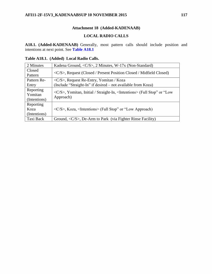
AFI11-2F-15V3_KADENAABSUP 10 NOVEMBER 2015 117
Attachment 18 (Added-KADENAAB)
LOCAL RADIO CALLS
A18.1. (Added-KADENAAB) Generally, most pattern calls should include position and
intentions at next point. See Table A18.1
Table A18.1. (Added) Local Radio Calls.
2 Minutes Kadena Ground, <C/S>, 2 Minutes, W-17x (Non-Standard)
Closed
Pattern <C/S>, Request (Closed / Present Position Closed / Midfield Closed)
Pattern Re-
Entry
<C/S>, Request Re-Entry, Yomitan / Koza
(Include “Straight-In” if desired – not available from Koza)
Reporting
Yomitan
(Intentions)
<C/S>, Yomitan, Initial / Straight-In, <Intentions> (Full Stop” or “Low
Approach)
Reporting
Koza
(Intentions)
<C/S>, Koza, <Intentions> (Full Stop” or “Low Approach)
Taxi Back Ground, <C/S>, De-Arm to Park (via Fighter Rinse Facility)

118 AFI11-2F-15V3_KADENAABSUP 10 NOVEMBER 2015
Attachment 19 (Added-KADENAAB)
F-15C TANKER ADMIN PROCEDURES
A19.1. (Added-KADENAAB) General Guidance. It is the responsibility of the flight lead or
mission commander to coordinate with tanker assets the day prior to the mission, if known. If
short notice tankers become available, the flight lead or mission commander will make a
reasonable effort to coordinate with the tanker aircraft commander or flight lead prior to step.
Opportune AR situations are the one exception to this policy.
A19.2. (Added-KADENAAB) Preflight Planning. Air refueling specifics will be outlined in
the tanker coordination sheet for daily flying or in the appropriate SPINS/ATO for exercises. The
18 OSS/OSO is responsible for issuing the tanker coordination sheet for daily 18 WG AAR
operations. Squadron scheduling shops will adhere to the policies and timelines as determined by
18 OSS/OSO.
A19.2.1. (Added-KADENAAB) Ops Supervision. Squadron operations supervisors will
confirm the status of tankers and/or receivers before stepping aircrew (See Paragraph 8.15.1
Step Brief). Each squadron is responsible for notifying all affected players if there are
changes to the plan. Additionally, the SOF will monitor tankers/receivers and pass any real-
time changes to the affected players as time and conditions permit.
A19.2.2. (Added-KADENAAB) Altitude Deconfliction. The standard AAR altitude for
tankers is FL240 in all tracks except MOOSE-2 and EDIX-1, -2, & -3. Tanker base altitude
in MOOSE-2 is FL230 and EDIX-1, -2, & -3 is FL210. Tankers operating in formation will
stack 500’ above the formation lead; i.e., lead tanker at FL240, #2 at FL245, etc. Receivers
will be assigned initial rendezvous altitudes via the coordination sheet. Receivers will
maintain a minimum of 1,000’ below the tanker altitude until visual or cleared higher by the
tanker. Subsequent receivers will be stacked 1,000’ below preceding flights; i.e., Bat 1,
FL230, Demon 1, FL220, Cock 1, FL210.
A19.3. (Added-KADENAAB) Track Arrival. Unless coordinated otherwise, tankers will
enter the airspace and remain within 5NM of the border until reaching the refueling area, at
which time they will proceed direct to the anchor point and set up an orbit. Formations may
proceed direct to the tanker after radio contact is established and cleared by the tanker lead or
C2.
A19.4. (Added-KADENAAB) Command and Control. C2 should control tanker operations
in local airspace. Tanker operations can continue if the controlling agency falls out. The lead
tanker aircraft commander has the ultimate authority for conducting AAR.
A19.4.1. (Added-KADENAAB) Communications. C2 will provide control on AAR
rendezvous. Receivers will contact the boom when directed by C2 or the tanker. The standard
AAR rendezvous frequencies are 233.1 primary, 288.0 secondary. Table A18.1 outlines the
standard communications plan for local AAR.

AFI11-2F-15V3_KADENAABSUP 10 NOVEMBER 2015 119
Table A19.1. (Added) F-15 AAR Communications Plan.
A19.4.2. (Added-KADENAAB) Rendezvous. C2 will control operations in the air
refueling track and receiver/tanker rendezvous. All aircraft will set altimeter to 29.92 unless
directed otherwise by C2 or the lead tanker aircraft commander. At initial contact with C2
(on RDVZ) or the tanker lead (on Boom/AAR PRI), receivers will transmit position, altitude,
and weapons status (“Cock 1, 15 miles to the South at Flight Level 2-3-0, noses cold,
switches safe”).
A19.4.2.1. (Added-KADENAAB) Rendezvous Under C2. C2, in coordination with
the tanker lead, will direct receivers to the appropriate tanker. Receivers should contact
C2 as soon as possible and will change frequencies as directed by the controller.
Receivers will initially set altitudes outlined in the tanker coordination sheet. GCI may
redirect the receivers to different altitudes to effect the rejoin and/or manage multiple
receiver flights. It is important that C2 maintains positive control over rendezvous
operations in coordination with the tanker lead. Receivers not on time for their scheduled
ARCT may have to cancel AAR.
A19.4.2.2. (Added-KADENAAB) Rendezvous Without C2. Receivers may conduct
AAR operations without C2. In this case, receivers must adhere to the times and altitudes
outlined on the tanker coordination sheet until in radio contact with the tanker lead.
Initially, receivers will proceed toward the anchor point. After establishing radio contact
with the tanker on AAR (boom) primary, they may proceed directly to the tanker with
approval from the tanker lead. All receivers must be on the common AAR (boom)
primary frequency for deconfliction. The tanker lead has the ultimate authority to control
the flow of receivers to and from the rendezvous.
A19.5. (Added-KADENAAB) Night Procedures. Follow IMC procedures as described in
AFTTP 3-3.F-15C, even during night VMC. Highest digit receiver keeps anti-collision beacons
on for the flight until proceeding to the astern area, widest digit turns beacons on when highest

120 AFI11-2F-15V3_KADENAABSUP 10 NOVEMBER 2015
digit turns beacons off. Example: In a 4-ship, 4 has beacons on and all others are beacons off.
The 3 turns beacons on when 4 turns beacons off. When 4 returns to 3’s wing, 4 turns beacons on
and 3 turns beacons off.
A19.6. (Added-KADENAAB) Departing the AR Track. Receivers will depart the track high.
Climb to 1,000’ above the highest aircraft in the air refueling formation before initiating a turn;
i.e. in a formation of two tankers at FL240 and FL 245, receivers will depart at FL 255. Use
caution departing formation refueling ops during IMC. C2 will control AR track departures. In
the event C2 is not available, the tanker lead will control departure flow.
A19.7. (Added-KADENAAB) Emergency Procedures. Handle EPs in accordance with
applicable MDS guidance. Under normal circumstances, do not refuel with an EP or
malfunctioning AR system. If an emergency arises that requires air refueling, coordination
between tanker and receiver aircrew takes priority over all EMCON considerations.
A19.8. (Added-KADENAAB) Opportune Air Refueling. Opportune Air Refueling is a plan
to help coordinate real-time air refueling opportunities increasing 18 WG interoperability.
Opportune Air Refueling addresses daily mission changes (i.e., weather, receiver fallout, etc.)
where time does not allow use of the tanker coordination sheet. This includes airborne KC-135s
that have returned to the local area and have offload available. Flight leads will ensure all flight
members are properly briefed on AAR before using Opportune Air Refueling.
A19.8.1. (Added-KADENAAB) The Shogun In-flight Guide, Volume 1 F-15C, contains
the standard anchor point and altitude information for all local AR tracks.
A19.8.2. (Added-KADENAAB) Contact squadron ops sup to set up Opportune Air
Refueling. With squadron ops sup approval, squadron ops personnel will coordinate with 909
ARS Ops to determine tanker availability. The AR procedures in the preceding paragraphs
apply. Planned deviations will be specifically briefed. Receivers conducting Opportune Air
Refueling must obtain appropriate deconfliction before entering the tanker track.
A19.9. (Added-KADENAAB) Airspace. AR will be scheduled in local airspace via the tanker
coordination sheet. In the case where aerial refueling and ACBT are being conducted in the same
airspace, 18 OSS/OSO will assign altitude and/or geographic deconfliction on the daily airspace
sheet. When using altitude as the primary means of deconfliction, there must be a minimum of
2,000’ between floors and ceilings; e.g., Bat in EAGLE below FL180; AR in EAGLE above
FL200. This deconfliction plan will also be included on the tanker coordination sheet. Airspace
limited by altitude may restrict the number of flights able to refuel within the same timeframe.
A19.10. (Added-KADENAAB) Contingencies. Any changes to any part of the AAR plan
must be communicated to all players as soon as possible. After aircraft launch (receivers or
tankers), the SOF (or Shogun Control, during exercises/contingencies) via C2 will serve as the
focal point for distributing information. Any aircraft that cannot comply with the tanker
coordination sheet for any reason (fallout, weather, etc) will pass alibis to Shogun 10. Shogun 10
will attempt to contact all players affected by the change (flight discrete freqs, C2, Tiger Ops,
etc). Airborne aircraft and C2 should contact Shogun 10 for the most current information.
AFI11-2F-15V3_KADENAABSUP 10 NOVEMBER 2015 121
Attachment 20 (Added-KADENAAB)
F-15 ALTERNATE MISSIONS
A20.1. (Added-KADENAAB) Alternate missions for F-15s include Instruments, AHC, BFM,
ACM, or TI. See paragraph 8.11.3 for single-ship policy.
A20.1.1. (Added-KADENAAB) The flight lead is responsible for ensuring all participants
are aware of any alternate mission that may be flown. At a minimum, cover specific fallout
examples that may arise and the mission type that will result given that fallout.
A20.1.2. (Added-KADENAAB) Alternate missions will be less demanding or complex
than the primary mission. Approved missions from the in-flight guide (AHC, BFM, ACM
and TI) may qualify as an alternate mission, assuming they are less demanding or complex
than the primary. If multiple formations attend the same coordination brief, a BFM primary
mission may be upgraded to a more complex ACM mission due to MX fallout. Examples
follow:
A20.1.2.1. (Added-KADENAAB) Example 1. Primary mission is LFE 8vX (Cope
Thunder, Red Flag). Weather precludes launch of adversaries. F-15s decide to fly. A 4v4
Blue vs. Red Tactical Intercept (TI) mission is acceptable. Blue 1-4 executes with Blue
SPINs. Red 1-4 (formerly Blue 5-8) executes with LFE-briefed adversary Red SPINs.
Red must have pre-briefed a Red-air tactic. Limited maneuvering applies.
A20.1.2.2. (Added-KADENAAB) Example 2. Primary mission is ACT 4vX (Local
OCA/DCA), and maintenance fallout on the Blue side with no spare aircraft available
results in a 3-ship for Blue Air. Blue 1 may pull a Red Air player over to the Blue side
provided that player sat in the overall coordination brief. To transition from Red to Blue,
the pilot must be a qualified 2-Ship flight lead, at a minimum. If the player swapping
from Red to Blue was NOT in the tactical element brief, a missionized sortie CANNOT
be flown, but TI in accordance with AFTTP 3-1.F-15 is allowed.
A20.1.2.3. (Added-KADENAAB) Example 3. Primary mission is 4v4 TI. A 2v4 TI
mission may be flown. ACM, BFM, AHC, or Instruments may also be flown.
A20.1.2.4. (Added-KADENAAB) Example 4. Primary mission is ACM. BFM, AHC,
or Instruments may be flown.
A20.1.2.5. (Added-KADENAAB) Example 5. Primary mission is BFM. The only
fallout missions that may be flown are AHC or Instruments, unless multiple formations
attended the same coordination brief, and combining formations for ACM was briefed as
a fallout option.
A20.1.3. (Added-KADENAAB) During surge operations, combining flight members and
flexing between BFM and ACM is allowed to provide for logical flow and to maximize
training. All anticipated missions will be briefed in accordance with Attachment 21, Surge
Operations.
A20.1.4. (Added-KADENAAB) Use of Spare IPs for MQT, FLUG, and IPUG. The
SQ/DO or higher must concur with the spare IP plan. With SQ/DO approval, the following
situations can be modified on a case by case basis. The following details IP fallout options:

122 AFI11-2F-15V3_KADENAABSUP 10 NOVEMBER 2015
A20.1.4.1. (Added-KADENAAB) BFM. Briefed and flown as scheduled. No
mixing/matching of IP/Students.
A20.1.4.2. (Added-KADENAAB) ACM, TI, or ACT missions. There is an option for
a spare IP Red Air pilot to spare forward into the position of Blue 1 (or Blue 2 in the case
of FLUG or IPUG) if Blue 1 falls out. In order to spare forward, the following provisions
must be met:
A20.1.4.2.1. (Added-KADENAAB) The spare IP Red Air pilot must be a qualified
IP.
A20.1.4.2.2. (Added-KADENAAB) The spare IP Red Air pilot must be designated
prior to and attend the blue air element brief. Red air coordination for the fallout IP
will occur prior to step.
A20.1.4.2.3. (Added-KADENAAB) The spare IP Red Air pilot will review the
student’s grade book in advance.
A20.2. (Added-KADENAAB) AHC. See the Shogun In-flight Guide, Volume 1, F-15 or
AFTTP 3-3.F-15 for specific maneuvers.
A20.3. (Added-KADENAAB) BFM.
A20.3.1. (Added-KADENAAB) General. Load SCL-1. Use modified AIM-9 WEZ for
perch BFM, and full-up AIM-9M/X for Combat Perch and High Aspect BFM. Kill Criteria:
2 shots / 1 guns track. No AIM-120-only kills. Missile shots within the first 5 seconds on a
perch setup and pre-merge (neutral setup) shots do not count towards kills. 5,000’ Floor. 500’
Bubble.
A20.3.2. (Added-KADENAAB) BFM Objectives. See Table A19.1
Table A20.1. (Added) BFM Objectives.
Offensive Maneuver to a WEZ and kill while maintaining the offensive
Separate before going defensive.
Defensive
Defeat the initial threat of weapons employment
Deny subsequent weapons employment opportunities
Neutralize, separate, or go offensive.
High Aspect
Maneuver to a WEZ and kill the bandit.
Maneuver to gain the offensive
Separate before becoming defensive.
A20.3.3. (Added-KADENAAB) Perch Setups. In accordance with AFTTP 3-3.F-15
except starting altitude will be 18,000’ MSL and 6K/9K base airspeed 430 KIAS.
A20.3.4. (Added-KADENAAB) Combat Perch Setups. 16,000’-18,000’. 4AA. 2.5nm
line abreast. Check turn into defender. Offender calls “2.2 miles” and any aspect angle other
than 4. The Offender will call, “fight’s on” at any range between 2.2NM and 10K’. CMD
actuations will be limited to 4 actuations by the Defender, and no CMDs for the Offender.
The Offender will simulate an AA-11 shooter while the Defender employs to the full limits
of the AIM-9X.
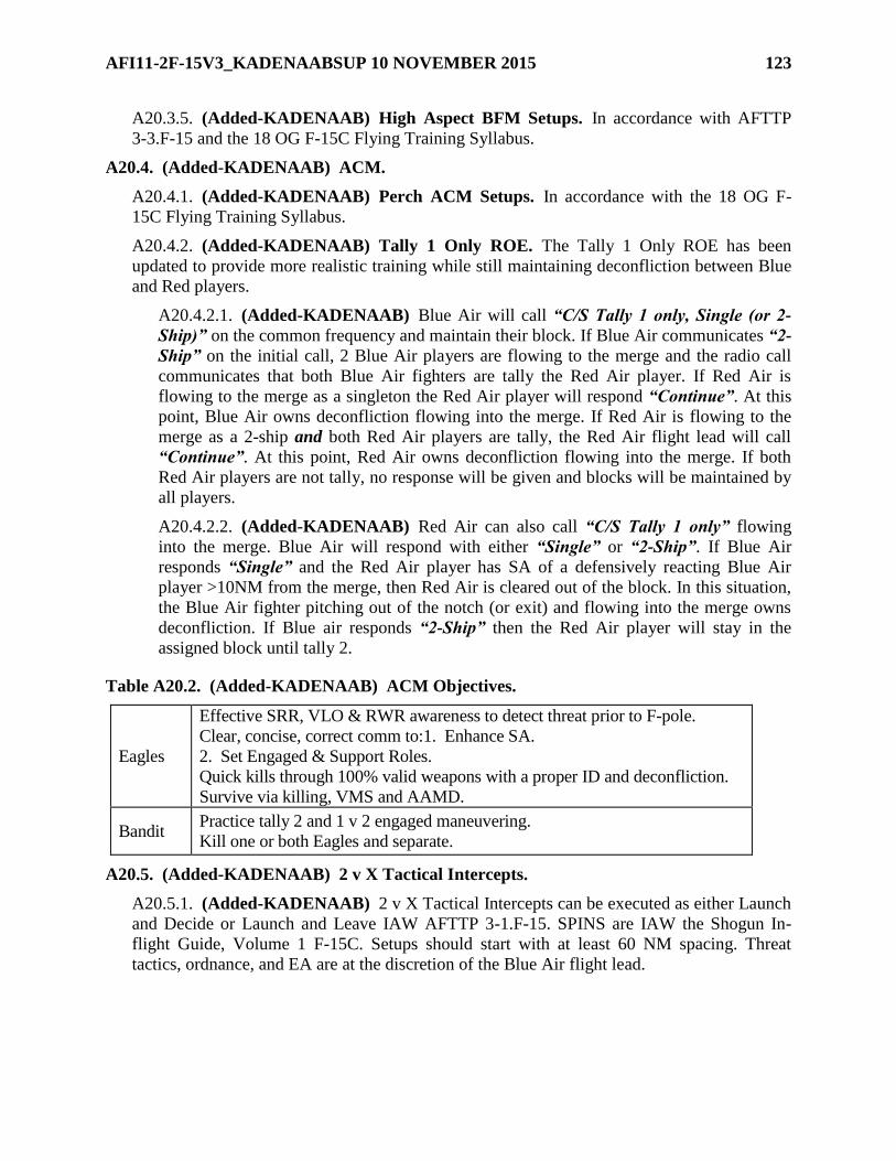
AFI11-2F-15V3_KADENAABSUP 10 NOVEMBER 2015 123
A20.3.5. (Added-KADENAAB) High Aspect BFM Setups. In accordance with AFTTP
3-3.F-15 and the 18 OG F-15C Flying Training Syllabus.
A20.4. (Added-KADENAAB) ACM.
A20.4.1. (Added-KADENAAB) Perch ACM Setups. In accordance with the 18 OG F-
15C Flying Training Syllabus.
A20.4.2. (Added-KADENAAB) Tally 1 Only ROE. The Tally 1 Only ROE has been
updated to provide more realistic training while still maintaining deconfliction between Blue
and Red players.
A20.4.2.1. (Added-KADENAAB) Blue Air will call “C/S Tally 1 only, Single (or 2-
Ship)” on the common frequency and maintain their block. If Blue Air communicates “2-
Ship” on the initial call, 2 Blue Air players are flowing to the merge and the radio call
communicates that both Blue Air fighters are tally the Red Air player. If Red Air is
flowing to the merge as a singleton the Red Air player will respond “Continue”. At this
point, Blue Air owns deconfliction flowing into the merge. If Red Air is flowing to the
merge as a 2-ship and both Red Air players are tally, the Red Air flight lead will call
“Continue”. At this point, Red Air owns deconfliction flowing into the merge. If both
Red Air players are not tally, no response will be given and blocks will be maintained by
all players.
A20.4.2.2. (Added-KADENAAB) Red Air can also call “C/S Tally 1 only” flowing
into the merge. Blue Air will respond with either “Single” or “2-Ship”. If Blue Air
responds “Single” and the Red Air player has SA of a defensively reacting Blue Air
player >10NM from the merge, then Red Air is cleared out of the block. In this situation,
the Blue Air fighter pitching out of the notch (or exit) and flowing into the merge owns
deconfliction. If Blue air responds “2-Ship” then the Red Air player will stay in the
assigned block until tally 2.
Table A20.2. (Added-KADENAAB) ACM Objectives.
Eagles
Effective SRR, VLO & RWR awareness to detect threat prior to F-pole.
Clear, concise, correct comm to:1. Enhance SA.
2. Set Engaged & Support Roles.
Quick kills through 100% valid weapons with a proper ID and deconfliction.
Survive via killing, VMS and AAMD.
Bandit Practice tally 2 and 1 v 2 engaged maneuvering.
Kill one or both Eagles and separate.
A20.5. (Added-KADENAAB) 2 v X Tactical Intercepts.
A20.5.1. (Added-KADENAAB) 2 v X Tactical Intercepts can be executed as either Launch
and Decide or Launch and Leave IAW AFTTP 3-1.F-15. SPINS are IAW the Shogun In-
flight Guide, Volume 1 F-15C. Setups should start with at least 60 NM spacing. Threat
tactics, ordnance, and EA are at the discretion of the Blue Air flight lead.

124 AFI11-2F-15V3_KADENAABSUP 10 NOVEMBER 2015
Table A20.3. (Added-KADENAAB) TI Blue Air Objectives.
Eagles
Effective sensors to build the 3-D picture and target all factor groups
Execute intercepts to WEZ manage/WEZ deny
Clear, Concise, Correct SA enhancing comm
100% valid ID and weapons employment
Survive via killing, AAMD, IRMD, and flow
A20.6. (Added-KADENAAB) Tactical Exercises. The following exercises can be briefed as
“standard” and used to/from training areas or when weather / fuel precludes a full-up
engagement.
A20.6.1. (Added-KADENAAB) Multiple Weapons Exercise. In accordance with AFTTP
3-3.F-15.
A20.6.2. (Added-KADENAAB) Tracking Gun Exercise. In accordance with AFTTP 3-
3.F-15.
A20.6.3. (Added-KADENAAB) Medium Angle Snap Shot Exercise. In accordance with
AFTTP 3-3.F-15.
A20.6.4. (Added-KADENAAB) High Angle Snap Shot Exercise. In accordance with
AFTTP 3-3.F-15.
A20.6.5. (Added-KADENAAB) BVR AAMD. In accordance with AFTTP 3-3.F-15,
AFTTP 3-1.F-15, and the Shogun In-flight Guide, Volume 1 F-15C.

AFI11-2F-15V3_KADENAABSUP 10 NOVEMBER 2015 125
Attachment 21 (Added-KADENAAB)
SURGE OPERATIONS
A21.1. (Added-KADENAAB) This policy establishes operational guidance to ensure safe,
efficient F-15 surge operations. Surges allow for efficient sortie generation. The nature of a surge
also carries an increased risk in comparison to the normal flying schedule. When that risk
exceeds an acceptable level, squadron leadership or the flight lead will call “Knock it off.” The
following guidance applies for surges:
A21.1.1. (Added-KADENAAB) The mixing and matching of flight lead and wingmen (in
accordance with current Letter of X’s) is authorized as long as the overall guidance of this
policy is met.
A21.1.2. (Added-KADENAAB) All flyers will receive the same mass brief. Two or more
squadrons desiring the option of mixing and matching flight leads and wingmen must either
brief together in the same location or receive identical briefings created by wing weapons if
briefings are in separate locations. The intent is to prevent single ship missions when BFM or
ACM can be accomplished. Operations supervisors will use good judgment and coordinate
pairings.
A21.1.3. (Added-KADENAAB) Primary mission and surge tactical objectives (BFM,
ACM, TI, etc.) will be thoroughly briefed.
A21.1.4. (Added-KADENAAB) Mass brief will cover WX, NOTAMS, admin, standard
out/back, and TRs.
A21.1.5. (Added-KADENAAB) Desired learning objectives and KIO criteria will be
thoroughly briefed. Due to the increased tempo of surge operations, more conservative KIO
criteria will be used by flight leads.
A21.1.6. (Added-KADENAAB) There will be a dedicated portion of the mass brief
covering all pertinent tactical phases of flight for the primary mission. The 18 WG and CAF
F-15 tactical standards will be utilized.
A21.1.7. (Added-KADENAAB) Red Air options will be briefed and understood. A hard
copy of a Red Air playbook will be available to each pilot for review.
A21.1.8. (Added-KADENAAB) MQT students may fly in the surge with the following
guidance:
A21.1.9. (Added-KADENAAB) The primary option for an MQT student is to brief and fly
with a dedicated IP. MQT students will only fly missions that are commensurate with their
progress in the MQT syllabus. Example: If MQT student is complete with BFM phase and is
currently in the ACM phase, then student can fly BFM or their current MQT ACM Upgrade
sortie with the dedicated/briefed IP. They cannot fly in a TI or ACT mission.
A21.1.10. (Added-KADENAAB) However, any IP can fly with any MQT pilot, assuming
both attended the surge brief. If this option is used, the type of mission will reduce to one that
the student has already demonstrated proficiency in. Example: If MQT student is complete
with BFM phase and is currently in the ACM phase, they can fly BFM. They cannot fly the
MQT ACM upgrade sortie, or any TI or ACT mission.

126 AFI11-2F-15V3_KADENAABSUP 10 NOVEMBER 2015
A21.1.11. (Added-KADENAAB) Alternate missions will be briefed. Alternate missions
will be less demanding than the primary and conform to standing alternate mission guidance.

AFI11-2F-15V3_KADENAABSUP 10 NOVEMBER 2015 127
Attachment 22 (Added-KADENAAB)
CROSS COUNTRY SAMPLE REQUEST
Figure A22.1. (KADENAAB) Cross Country Sample Request
MEMORANDUM FOR XX FS/DO DATE
XX FS/CC
18 OG/CC
FROM: XX FS/XX (CAPT XXXX)
SUBJECT: Cross Country Request
1. Request approval for a 4-ship cross country beginning on <date> and returning on <date>.
The itinerary and pilot qualifications are:
ITINERARY
DATE FROM (T/O) TO (LAND) FUEL (IAF) PPR
REM 21 Jun Kadena AB, JA (0800) Kwang Ju AB, ROK (0930) 4400# C03
Gas & Go
21 Jun Kwang Ju AB, ROK (1100) Osan AB, ROK (4430) 4700# 040702
RON
22 Jun Osan AB, ROK (1030) Kwang Ju AB, ROK (4400) 4700# F01
Gas & Go
22 Jun Kwang Ju AB, ROK (1100) Osan AB, ROK (4430) 4700# 040702
RON
24 Jun Osan AB, ROK (1400) Kadena AB, JA (1530) 4400# N/A
Return
QUALIFICATIONS
NAME RANK QUAL EXP LVL WX HRS
(TOT/PAA)
Ragman, Joe S. Capt IP/FE E A 1900/1400
Paper, Wase T. Lt WG I C 400/150
Galland, Adolf G. Maj IP E B 4,000/300
Bader, DouglasLtWGEC5,000/200
2. The purpose of this cross country is to conduct Off-Station Navigation Proficiency Training
and increase familiarity with the Korean AOR.
JOE B. AIRFORCE, Capt, USAF
F-15 Aircraft Commander

128 AFI11-2F-15V3_KADENAABSUP 10 NOVEMBER 2015
1st Ind to XX FS/XX, DATE, Cross Country Request
XX FS/DO
MEMORANDUM FOR XX FS/CC
Recommend approval/disapproval.
IAM A. WONDER, Lt Col, USAF
Operations Officer, XX FS
2d Ind, XX FS/CC
MEMORANDUM FOR 18 OG/CC
Recommend approval/disapproval.
JOHN Q. COMMANDER, Lt Col, USAF
Commander, XX Fighter Squadron
3d Ind, 18 OG/CC
MEMORANDUM FOR XX FS/XX
Approved/disapproved.
THEBIG NMI BOSS, Colonel, USAF
Commander, 18th Operations Group

AFI11-2F-15V3_KADENAABSUP 10 NOVEMBER 2015 129
Attachment 23 (Added-KADENAAB)
FITS GUIDANCE
Table A23.1. (Added-KADENAAB) Fighter Index of Thermal Stress (FITS) Reference
Values and Flag Colors.
Dry Bulb
Temperature
Zone Dew Point Temperature
(F) 30 40 50 60 70 80 90 100 >110
70 70 73 76 81 86 X X X X
75 74 77 80 84 89 X X X X
80 NORMAL 77 80 83 87 92 98 X X X
85 81 83 86 90 95 101 X X X
90 84 87 90 93 98 104 110 X X
95 88 90 93 96 101 108 112 X X
100 91 93 96 99 104 109 115 122 X
105 CAUTION 94 96 99 102 107 112 118 124 X
110 97 99 102 105 109 114 120 126 133
115 100 102 105 109 112 117 123 129 136
120 DANGER 104 105 108 111 115 120 125 131 138
A23.1. (Added-KADENAAB) FITS Caution Zone. The following procedures should be
implemented:
A23.1.1. (Added-KADENAAB) Be alert for symptoms of heat stress.
A23.1.2. (Added-KADENAAB) Drink plenty of non-caffeinated fluids.
A23.1.3. (Added-KADENAAB) Avoid exercise 4 hours prior to take off.
A23.1.4. (Added-KADENAAB) Limit ground operations time to 90 minutes outside an air-
conditioned environment. An F-15C with canopy closed and an operating ECS qualifies as an
air-conditioned environment.
A23.2. (Added-KADENAAB) FITS Danger Zone. In addition to the above procedures:
A23.2.1. (Added-KADENAAB) Limit ground operations to 45 minutes time outside air-
conditioned environment.
A23.2.2. (Added-KADENAAB) After the second ground abort under FITS Danger, the
pilot must go back into an air-conditioned environment for 30 minutes of rest.

130 AFI11-2F-15V3_KADENAABSUP 10 NOVEMBER 2015
Attachment 24 (Added-KADENAAB)
18 WG MESL
Table A24.1. (Added-KADENAAB) 18 WG Minimum Essential Systems List (MESL).
SYSTEM/SUBSYSTEM TNG
SORTIE
Deployment Sortie
(note 1,2)
Airframe X X
Cockpit & Fuselage Compartments X X
Landing Gear X X
Flight Controls X X
Turbofan Power plant X X
Auxiliary Power plant X X
AC/Press (Manuel Mode Only) X X
Electric Power Supply X X
Ext Lighting System (per OG night stds) X X
Interior Light Sys/Caution light Panel X X
Hydraulic and Pneumatic Power Supply X X
Fuel System X X
Oxygen System X X
Miscellaneous Utilities X X
Instruments X X
Autopilot
Control Augmentation System X X
Built-In-Test Display Group X X
Malfunction Analysis and Recording X X
Integrated Guidance and Flight Control X X
UHF/VHF Communication X(note 3) X(note 3)
Have Quick X
Ky58 including crypto (note 4) X*
Integrated CNI Control Set X X
Intercommunication System for B/D N/A N/A
IFF Transponder Set
Mode 1 / 2
Mode 3/C
Mode 4 including crypto
X*
X*
X*
X
IFF Interrogator Set X*
Instrument Landing Set X X
EGI System including crypto X X
Inertial Navigation (RLG) X X
Fighter Data Link System including crypto X X*
Tactical Air Navigation X X
Radar Set X* X*3

AFI11-2F-15V3_KADENAABSUP 10 NOVEMBER 2015 131
Indicator Group OD-60/A (VSD) X* X*
Head Up Display Set X
Digital Video Recorder System X
MPCD/FPCD X X
Joint Helmet Cueing X*
Weapons Delivery (note 5) X
Gun System X
RWR ALR-56C X
Interference Blanker X X
Electronic Warfare Warning Set
ALQ-135 Band 1, 2 X*
ALQ-135 Band 3 X
Countermeasures Dispenser X
Emergency Equipment X X
Explosive Device and Components X X
Notes:
1. OPLAN sorties will be Full System List (FSL) unless determined by 18 OG/CC.
2. Any reduction in system requirements will be: 1) coordinated with MX to ensure the
capability of correction is available at the intended destination and 2) coordinated with
Tactical Command and Control to ensure the deployment aircraft with a reduced MESL
will not be rolled into a combat sortie. If the requirement to fly a combat sortie exists and
cannot be waived, or the parts/capability for a MX solution does not exist at or enroute to
the deployed base, before the aircraft will be required to fly a combat sortie then the
OPLAN MESL is FSL.
3. Only need 1 UHF radio for deployment/Local training.
4. One operational KY radio required per four ship.
5. All Eight (8) Aim-120 & (4)/Aim-9 Stations are required.
*Can be waived by squadron Top 3 depending on mission/weather constraints.