by order of the commander lakenheath...
TRANSCRIPT
BY ORDER OF THE COMMANDER
RAF LAKENHEATH (USAFE)
LAKENHEATH INSTRUCTION
13-201
2 FEBRUARY 2017
Command and Control Operations
AIRFIELD OPERATIONS
PROCEDURES
COMPLIANCE WITH THIS PUBLICATION IS MANDATORY
ACCESSIBILITY: Publications and forms are available on the e-Publishing website at
www.e-Publishing.af.mil for downloading or ordering.
RELEASABILITY: There are no releasability restrictions on this publication.
OPR: 48 OSS/OSA
Supersedes: LAKENHEATHI 13-201,
22 October 2012
Certified by: 48 OG/CC
(Col Donn C. Yates)
Pages: 96
This publication implements Air Force Policy Directive (AFPD) 13-2, Air Traffic, Airfield,
Airspace and Range Management, and interfaces with Air Force Instruction (AFI) 13-204
Volume 3, Airfield Operations Procedures and Programs. It establishes procedures and
guidelines relating to Air Traffic Control (ATC) services, operation of the airfield, associated
equipment, and local flying. It applies to all units assigned to 48th Fighter Wing (48 FW). Refer
recommended changes and questions about this publication to the OPR listed above using the AF
Form 847, Recommendation for Change of Publication; route AF Form 847 from the field
through the appropriate chain of command. Ensure that all records created as a result of
processes prescribed in this publication are maintained in accordance with Air Force Manual
(AFMAN) 33-363, Management of Records, and disposed of in accordance with Air Force
Records Information Management System (AFRIMS) Records Disposition Schedule (RDS).
SUMMARY OF CHANGES
This document has been substantially revised and must be completely reviewed. Major changes
include: Suspension of Runway (RWY) operations following heavy aircraft arrival/departure,
Runway Surface Condition (RSC) and Runway Condition Reading (RCR) procedures,
Instrument Flight Rules (IFR) departure procedures, standard climb-out altitude, radar flight
following requirements for STANTA, Visual Flight Rules (VFR) pattern altitudes and
procedures, Special VFR authorization, hung ordnance and missile procedures, non-radar
2 LAKENHEATHI13-201 2 FEBRUARY 2017
procedures, civil use of Unmanned Aerial Systems (UAS) on RAF Lakenheath (LKH), paradrop
operations, Large Force Exercise (LFE) taxi procedures, and coordination requirements for
Uncontrolled Airfield Operations (UAO).
1. AUTHORITY AND RESPONSIBILITIES. .......................................................... 3
2. AIRFIELD INFORMATION. ................................................................................ 4
Table 2.1. Routine Large Frame Parking. ................................................................................ 11
Table 2.2. Contingency Large Frame Parking (May limit aircraft movement on TWY N). ... 11
Table 2.3. Fighter Parking Maximum on Ground (MOG). ...................................................... 11
Table 2.4. LKH Frequencies/UHF Channelization. ................................................................. 12
3. FLYING AREAS. ................................................................................................... 20
4. FLIGHT PLANNING. ............................................................................................ 22
5. GROUND OPERATIONS...................................................................................... 23
6. DEPARTURE PROCEDURES. ............................................................................. 25
7. ARRIVAL PROCEDURES. ................................................................................... 29
8. HELICOPTER OPERATIONS. ............................................................................. 40
9. EMERGENCY PROCEDURES. ............................................................................ 44
10. MISCELLANEOUS PROCEDURES. ................................................................... 55
11. PARADROP PROCEDURES. ............................................................................... 68
12. NON-RADAR OPERATIONS. .............................................................................. 71
LAKENHEATHI13-201 2 FEBRUARY 2017 3
Attachment 1— GLOSSARY OF REFERENCES AND SUPPORTING INFORMATION 74
Attachment 2— UNCONTROLLED AIRFIELD OPERATIONS (UAO) 83
Attachment 3— AIRFIELD DIAGRAM 88
Attachment 4— CMATZ 89
Attachment 5— MVA CHART 90
Attachment 6— STEREO FLIGHT PLANS 91
Attachment 7— FIGHTER DEPARTURES/ARRIVALS 92
Attachment 8— RADAR TRAFFIC PATTERNS 93
Attachment 9— HELICOPTER VFR DEPARTURES/ARRIVALS 94
Attachment 10— LAKENHEATH DROP ZONE 95
Attachment 11— RAF MILDENHALL VFR RECOVERY POINTS 96
1. AUTHORITY AND RESPONSIBILITIES.
1.1. Authority. This publication interfaces with Air Force Instruction (AFI) 13-204 Volume
3, AFI 11-202 Volume 3, General Flight Rules, Federal Aviation Administration Order
(FAAO) 7110.65, Air Traffic Control (ATC), Regulatory Article (RA) 3000 Series, Air
Traffic Management, Manual of Military Air Traffic Management (MMATM), Civil
Aviation Authority Publication (CAP) 774, International Civil Aviation Organization (ICAO)
procedures, Military Air Traffic Services, Royal Air Force (RAF) Military Radar and
Military Air Traffic Operation (MATO) Procedures and Patterns for East Anglia.
1.2. Responsibilities. 48th Operations Group Commander (OG/CC) will ensure this
instruction is maintained, enforced, viable, and is the waiver authority for local policies
contained herein, unless otherwise specified.
1.2.1. 48th Operations Support Squadron Commander (OSS/CC) will ensure revisions to
this instruction are fully coordinated with applicable base agencies.
1.2.2. 48 OG Standardization and Evaluation (OG/OGV) will validate and disseminate
interim changes and applicable attachments to this instruction via an appropriate medium.
1.2.3. 48 OSS Airfield Operations Flight (OSS/OSA) will compile, consolidate, and
coordinate changes to this instruction and is responsible for its content.
1.2.4. 48 FW Scheduling (OSS/OSOS) will ensure Temporary Duty (TDY) units flying
local missions are assigned a host unit. Host units will brief and ensure understanding of
procedures contained in this instruction before a TDY unit begins flying local sorties.
1.2.5. Non-hosted units shall contact the 48 OSS, Airfield Operations Flight Commander
(AOF/CC), 48 OG/OGV and 48 FW Safety (FW/SE) to schedule these briefings prior to
flying local sorties.

4 LAKENHEATHI13-201 2 FEBRUARY 2017
1.3. Recommending Changes. The 48 OSS/OSA reviews this instruction bi-annually; submit
all requested changes to the AOF/CC or designated representative.
2. AIRFIELD INFORMATION.
2.1. Runways (RWY) and Taxiways (TWY). RWY 06/24 is 8,998 feet long by 150 feet
wide, the airfield elevation 32 feet mean sea level (MSL); RWY 24 is the primary instrument
RWY. The first 500 feet of RWY 06 and the first 1000 feet of RWY 24 are grooved
concrete; the remaining is a porous friction surface (PFS). RWY 06 overrun is 997 feet long
and RWY 24 is 938 feet long; both are non-load bearing. See Attachment 3 for airfield
diagram depicting RWY/TWY designators.
2.1.1. RWY Restrictions.
2.1.1.1. To prolong the lifespan, reduce wear and prevent damage/shifting of the PFS
portion of the RWY, all aircraft turns on, onto, or off of the RWY (including tows)
must only be accomplished on the concrete portion. Heavy utility vehicles, such as
fire trucks, must also enter and exit the RWY from the concrete ends.
2.1.1.2. Short takeoff and vertical landing aircraft are not permitted to perform
vertical takeoffs or landings on/over the PFS.
2.1.2. Permanently Closed/Unusable Portions of the Airfield.
2.1.2.1. The pavement between point 2 north and TWY Whiskey (commonly referred
to as the Gantry area) is not usable for aircraft operations.
2.1.2.2. The pavement at Juliet bubble is permanently closed.
2.1.3. RWY Selection Procedures.
2.1.3.1. RAF Lakenheath (LKH) Control Tower (TWR) Watch Supervisor/Senior
Controller (WS/SC) will select the RWY in use based on weather, availability of
arresting gear, airfield lighting, and opportunity for practice approaches.
2.1.3.2. Prior to commencing a RWY change, TWR WS/SC will pre-coordinate with
LKH Radar Approach Control (RAPCON) and Supervisor of Flying (SOF).
2.1.3.3. RWY Change Notification Procedures.
2.1.3.3.1. Upon commencing and completing a RWY change, TWR will inform
RAPCON, Airfield Management Operations (AMOPS), 48 OSS Weather Flight
(OSS/OSW), 48th Civil Engineer Squadron Fire and Emergency Services
(CES/CEF), and RAF Mildenhall (MLD) Tower. RAPCON and TWR will also
broadcast an advisory on all appropriate frequencies. TWR will update the
Automatic Terminal Information Service (ATIS).
2.1.3.3.2. AMOPS will advise Transient Alert (TA), 48 FW Command Post
(FW/CP), and 48 CES Power Production (CES/CEOFP).
2.1.3.3.3. CES/CEOFP will request CES/CEF assistance to reconfigure the cables
when needed.
2.1.3.3.4. SOF will notify OG/CC and each Squadron Operations Supervisor
(Ops Sup).
LAKENHEATHI13-201 2 FEBRUARY 2017 5
2.2. Control of Ground Traffic in the Controlled Movement Area (CMA).
2.2.1. CMA. See also Lakenheath Instruction (LAKI) 13-202, Airfield Driving, for
vehicle operation procedures in the CMA.
2.2.1.1. The CMA is defined as the RWY, overruns, and all areas within 150 feet of
the paved surface of the RWY and overruns. The areas between the RWY hold lines
and the RWY are included in the CMA.
2.2.1.2. TWR is responsible for controlling the movement of vehicles, equipment,
and personnel in the CMA. TWR will continuously monitor the ramp net during
airfield operating hours.
2.2.1.3. Construction in the CMA.
2.2.1.3.1. All construction must be pre-approved by the Airfield Manager (AFM).
2.2.1.3.2. AMOPS will inform TWR of pertinent data, including radio call sign.
2.2.1.3.3. Work personnel must follow all procedures listed in LAKI 13-202.
2.2.1.3.4. The 48th Civil Engineer Squadron (48 CES) will provide an escort
vehicle for construction vehicles/personnel who do not have two-way
communication with TWR.
2.2.1.4. In the event of radio failure, all vehicles and personnel will exit the RWY
and remain a minimum of 150 feet from the edge of the RWY or overruns until two-
way radio communication with TWR is re-established.
2.2.1.4.1. TWR will immediately notify AMOPS when two-way communications
with any vehicle or personnel within the CMA is lost.
2.2.1.4.2. AMOPS will respond to vehicles and personnel within the CMA when
loss of two-way communications happens to provide an escorted departure from
the CMA.
2.2.1.4.3. If TWR is unable to reestablish two-way radio communication with
personnel within the CMA, controllers shall flash the RWY lights on and off
and/or use light gun signals to alert personnel to immediately vacate the area.
2.2.1.5. AMOPS and 48 CES/CEF will continuously monitor the ramp and crash nets
respectively.
2.2.2. Uncontrolled Movement Area. The uncontrolled movement area is defined as
TWYs (excluding the portion between the RWY and hold lines), aircraft parking areas,
protected aircraft shelters, and bubble parking areas.
2.2.3. RWY access for personnel and vehicles.
2.2.3.1. Authorized vehicles are permitted to cross the RWY only when in direct
two-way radio communication with TWR and verbal approval is granted by TWR.
Authorized vehicles will only cross the RWY for mission-essential duties. To the
maximum extent possible vehicles will use the airfield perimeter road to transit
between the north and south sides of the airfield.
6 LAKENHEATHI13-201 2 FEBRUARY 2017
2.2.3.2. Vehicles escorting a towed and/or emergency aircraft must be in two-way
radio contact with TWR if a RWY crossing is required.
2.2.3.3. Procedures for RWY access during TWR and AMOPS closures.
2.2.3.3.1. When TWR closes, TWR will broadcast on the RAMP and CRASH
NETS: “ATTENTION ON THE NET, LAKENHEATH TOWER IS NOW
CLOSED. FOR ACCESS TO THE RUNWAY, CONTACT EAGLE OPS ON
THIS NET.”
2.2.3.3.2. All vehicles shall contact 48 FW/CP (call sign: EAGLE OPS) when
exiting or requesting access to utilize any portion of the CMA.
2.2.3.3.3. 48 FW/CP will monitor the RAMP and CRASH NETS and verify the
airfield status for each vehicle, stating, “(CALL SIGN), EAGLE OPS, AIRFIELD
CLOSED, PROCEED AT YOUR DISCRETION, USE CAUTION, REPORT
OFF,” or, if mistakenly called when the TWR is open, “(CALL SIGN), EAGLE
OPS, AIRFIELD OPEN, CONTACT TOWER FOR CMA ACCESS.”
2.2.3.3.4. When TWR opens, TWR will broadcast on the RAMP and CRASH
NETS: “ATTENTION ON THE NET, LAKENHEATH TOWER IS NOW
OPEN. ALL VEHICLES RESPOND WITH CALL SIGN AND POSITION IN
THE CMA.”
2.2.3.3.5. AMOPS will conduct a RWY sweep prior to opening the airfield to
ensure that all vehicles are accounted for in the CMA. Once all vehicles are
accounted for, TWR will broadcast on the RAMP and CRASH NETS: “TOWER
HAS CONTROL OF THE RUNWAY.”
2.3. ATC Facilities.
2.3.1. Normal airfield, TWR, and AMOPS operating hours are Monday through
Thursday 0600-2200L and Friday 0600L-1800L.
2.3.1.1. The airfield, TWR, and AMOPS are closed on all United States (US)
holidays and United Kingdom (UK) Bank Holidays.
2.3.1.2. The airfield, TWR, and AMOPS are closed on all 48 FW Goal Days, No-Fly
Days, and USAFE Family Days. AMOPS will issue a closure NOTAM and inform
TA, Barrier Maintenance, and 48 CES/CEF at least 3 days before the closure.
2.3.2. RAPCON operates 24 hours a day, 7 days a week.
2.3.3. 48 FW/CP is the point of contact (POC) for initiating short-notice procedures to
open the airfield outside normal operating hours.
2.3.3.1. 48 FW/CP will request authorization from 48 OG/CC or designated
representative.
2.3.3.2. If authorization is granted, 48 FW/CP will then notify designated 48
OSS/OSA and 48 OSS/OSW representatives, who will in turn contact any additional
personnel needed to open.
2.3.3.3. 48 FW/CP will notify any additional agencies required by the original
requestor (e.g. TA, Fuels personnel, etc.).
LAKENHEATHI13-201 2 FEBRUARY 2017 7
2.3.3.4. 48 OSS/OSA will identify designated representatives (see 2.3.3.2.) in writing
to 48 FW/CP.
2.3.3.5. The response time for 48 OSS/OSA personnel to open facilities is 90
minutes.
2.3.4. OG/CC approval is required for any wing or transient operation (including aircraft
diverts from MLD) that requires the airfield be open outside of published hours. For
operations during quiet hours, see paragraph 2.17. Note: OG/CC approval may be
obtained via the approval of the flying schedule. Aircraft requiring the airfield be open
more than 30 minutes after the approved scheduled time will require separate approval.
The airfield will not remain open, and TWR will not provide ATC instructions without
OG/CC approval. TWR will issue an advisory that TWR and the airfield are closed, and
recommend termination of operations if necessary.
2.3.4.1. TWR and AMOPS will open the RWY 60 minutes prior to an aircraft’s
Estimated Time of Arrival (ETA) or Estimated Time of Departure (ETD).
2.3.4.2. For departures, the airfield (TWR and AMOPS) will remain open for 30
minutes after last departure.
2.3.4.3. For arrivals, the airfield (TWR and AMOPS) will remain open for 30
minutes after last landing or when advised by the pilot of engine shutdown,
whichever is first.
2.3.5. Both TWR and AMOPS must be on-duty for aircraft operations except in
accordance with (IAW) Attachment 2, Uncontrolled Airfield Operations (UAO).
2.4. Airfield Lighting Systems.
2.4.1. RWY 06/24 has Precision Approach Path Indicators (PAPI), High Intensity RWY
Lights (HIRL), RWY End Identifier Lights (REIL), High Intensity Approach Lights
(HIAL), and sequenced flashing lights (SFL). An airfield beacon is located on the north
side of the airfield.
2.4.2. Lighting Inspections.
2.4.2.1. AMOPS will inspect airfield lighting, including obstruction lighting daily.
2.4.2.2. 48 CES airfield lighting personnel will check the approach lighting system
and SFLs and report outages to AMOPS.
2.4.2.3. AMOPS will document unserviceable light outages.
2.4.2.4. AMOPS will contact 48 CES/CEF via telephone when outages render a
lighting system unusable during night or low visibility flying operations outside 48
CES normal operating hours.
2.4.3. 48 CES airfield lighting personnel will report to AMOPS at 0800L hours every
weekday morning the airfield is open to obtain the prior day’s outage report. They will
also make every effort to repair all lighting deficiencies the same day and return to
AMOPS at the end of each duty day to report repairs, system status, and any pertinent
information.
8 LAKENHEATHI13-201 2 FEBRUARY 2017
2.4.4. TWR has control of the airfield lighting panel and will operate airfield lights and
visual aids IAW MMATM, FAAO JO 7110.65, and local operating procedures (LOP),
for all aircraft operations.
2.4.5. Inoperative HIAL system procedures:
2.4.5.1. TWR will (if initially identifying the outages) advise AMOPS, RAPCON,
and all aircraft under their control of the outage.
2.4.5.2. AMOPS will advise TWR, RAPCON, and 48 FW/CP of airfield lighting
outages, and process a Flight Safety Notice to Airmen (NOTAM).
2.4.5.3. RAPCON will advise Swanwick Mil ATC and aircraft under their control of
the outage.
2.4.5.4. 48 FW/CP will notify the 492/493/494 Fighter Squadrons (FS), 56 Rescue
Squadron (RQS), and the OG/CC of the outage.
2.4.5.5. Upon restoration of the approach lights, all agencies will make the same
notifications.
2.4.6. When TWR is closed, changes to airfield lighting will be coordinated through 48
CES/CEF who will coordinate changes with 48 CES airfield lighting personnel.
2.5. Aircraft Arresting Systems.
2.5.1. Normal cable configuration will be the last four cables for the RWY in use
available, with the first two cables unavailable. The minimum arresting system
requirement for fighter operations is at least one departure end Barrier Arresting Kit-12
(BAK-12). Arresting systems are numbered one to six, starting at the RWY 06 approach
end E-5 cable.
2.5.1.1. E-5 cables (one and six) are located 95 feet into each overrun.
2.5.1.2. Single system (50000 pounds [nominal] at 180 knots maximum) BAK-12
(two and five) are located 1,200 feet from the threshold on each end.
2.5.1.3. Single system (50000 pounds [nominal] at 180 knots maximum) BAK-12s
(three and four) are located 2,500 feet from the threshold on each end.
2.5.1.4. BAK-12s can be engaged from either direction. Note: The Primary Crash
Alarm System (PCAS) will not be activated for practice cable engagements.
2.5.1.5. BAK-12 cables are tied down across the RWY to prevent excessive cable
bounce. A total of eight tie down straps are used per BAK-12 with four located either
side of the RWY centerline. If the cables are not tied down, 48 CES/CEOFP will
notify TWR and AMOPS. TWR will ensure aircraft are notified, and AMOPS will
issue a NOTAM as needed. Cables that are not tied down remain fully operational.
Additionally, the prescribed number of tie-downs, outlined above as eight per each
BAK- 12, should be kept in use to the maximum extent possible. AMOPS will notify
TWR and/or SOF when cable tie-downs are missing but will not suspend RWY
operations unless directed to do so by SOF, the AFM or 48 CES/CEOFP. Instead,
cable tie-downs will be replaced as soon as possible on a non-interference basis with
departure/recovery operations.
LAKENHEATHI13-201 2 FEBRUARY 2017 9
2.5.2. Successive cable engagements on the BAK-12s require a minimum interval of 15
minutes for re-set and recertification. No minimum time interval is established for
successive engagements on E-5 cables (one and six), however, re-set and recertification
are estimated to take in excess of 30 minutes. Engaged cables must be inspected, and
recertified by 48 CES/CEOFP prior to successive engagements. Additional time may be
required as the situation dictates. In extreme emergency situations, it is possible to have
one aircraft engaging the departure end arresting system and a successive aircraft
engaging an approach end arresting system; approach end cables should not be engaged
over a raised E-5 cable in the approach end underrun. If feasible, the second aircraft
should divert as directed by the SOF or 48 FW/CP.
2.5.2.1. In the rare event that a successive cable engagement is required, TWR must
be notified of any nonstandard cable status and/or debris (cable tape connectors, etc.)
left on the RWY.
2.5.2.2. If a cable is needed for a subsequent engagement before checks are
complete, the senior 48 CES/CEOFP official determines usability and notifies TWR
and AMOPS.
2.5.2.3. Following a cable engagement with subsequent inbound emergency aircraft
(that will not require a cable), the SOF may direct 48 CES/CEOFP to delay cable
inspection and recertification until any emergency aircraft have landed.
2.5.3. Recovery of aircraft into arresting systems while other aircraft are still on the
RWY will be at the discretion of the SOF.
2.5.4. All cables must be removed prior to the arrival and/or departure of EC/RC-135s
and U-2 aircraft.
2.5.5. AMOPS will notify 48 CES/CEOFP when cables need to be reconfigured or if a
system malfunction exists. Outside of normal duty hours, weekends and on holidays,
AMOPS will notify 48 CES/CEF who will, in turn notify 48 CES/CEOFP.
Approximately 20 minutes is required for cable reconfiguration.
2.5.6. ATC will issue cable advisory IAW FAAO JO 7110.65.
2.5.7. Maintenance and Inspection:
2.5.7.1. 48 CES/CEOFP will:
2.5.7.1.1. Perform maintenance inspections using the applicable technical orders/
regulations.
2.5.7.1.2. Perform daily, weekly, monthly, quarterly, semiannual, and annual
arresting system inspections.
2.5.7.1.3. Inspect and certify equipment following engagements and upon SOF,
TWR, or AMOPS request.
2.5.7.1.4. Cable status and service conditions are defined as follows:
2.5.7.1.4.1. Normal operation: Available for immediate use.
2.5.7.1.4.2. Limited service: Capable of one engagement with no rewind
capability.
10 LAKENHEATHI13-201 2 FEBRUARY 2017
2.5.7.1.4.3. Out of service: Not available and off RWY.
2.5.7.1.5. Notify AMOPS and TWR of cable limitations.
2.5.7.1.6. Contact TWR for access to arresting system equipment. 48
CES/CEOFP will be allowed to enter and work in cable huts during scheduled
flying after coordinating with TWR.
2.5.7.1.7. Perform uninterrupted recurring maintenance every Sunday from
sunrise to 1200L if the airfield is closed or after coordination with TWR.
2.5.7.1.8. Use only fully qualified personnel to maintain, inspect, and repair
equipment.
2.5.7.1.9. Correct equipment malfunctions or deficiencies if able, or report them
to AMOPS if they cannot be corrected.
2.5.7.1.10. Request 48 CES/CEF assistance through TWR and assist with
resetting and certifying cables after any engagement.
2.5.7.2. 48 CES/CEF will:
2.5.7.2.1. Set arresting system equipment to conform to direction of traffic, or as
requested by TWR, during 48 CES/CEOFP non-duty hours, weekends, holidays,
and wing down days.
2.5.7.2.2. Reset and/or help 48 CES/CEOFP reset the arresting system after each
engagement. Note: Only 48 CES/CEOFP personnel may recertify a cable.
2.5.7.2.3. Notify TWR when access to arresting system equipment is required
and when all personnel and vehicles are off the RWY after resetting and
inspecting the equipment.
2.5.7.2.4. Use only qualified personnel to maintain and inspect arresting system
equipment.
2.5.7.2.5. Report arresting system malfunctions to AMOPS, 48 CES/CEOFP, and
TWR.
2.5.7.3. TWR will:
2.5.7.3.1. Notify AMOPS before releasing arresting systems to 48 CES/CEOFP
for maintenance or configuration changes.
2.5.7.3.2. Notify pilots of the location of arresting system malfunctions or
deficiencies.
2.5.7.3.3. Afford RWY access priority to 48 CES/CEOFP to the maximum
extent.
2.5.7.4. AMOPS will:
2.5.7.4.1. Check and report obvious unsatisfactory conditions of the arresting
system that could compromise the system’s operation.
2.5.7.4.2. Notify 48 EMS/MXMMR (Crash Recovery) at DSN 226-2811 and 48
CES/CEF at least 15 minutes prior to any scheduled barrier certifications.

LAKENHEATHI13-201 2 FEBRUARY 2017 11
2.6. Parking Plan/Restrictions.
2.6.1. Refer 48 FW Plan 13-213, Aircraft Parking Plan. Note: Transient fighter aircraft
will normally park on the south side of the airfield (south of the RWY) or as directed by
AMOPS. Helicopters will normally park on TWY Whiskey.
2.6.2. Transient aircraft parking plan. The following tables allow routine parking,
refueling, upload/download of cargo, and taxi operations.
Table 2.1. Routine Large Frame Parking.
Table 2.2. Contingency Large Frame Parking (May limit aircraft movement on TWY N).
Table 2.3. Fighter Parking Maximum on Ground (MOG).
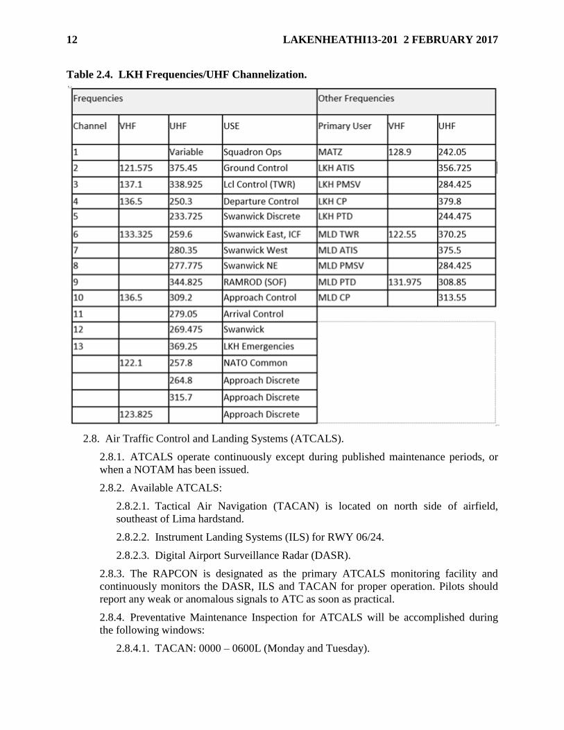
2.7. Local Frequencies/Channelization. The following frequencies/ultra-high frequency
(UHF) channels are utilized for LKH.
12 LAKENHEATHI13-201 2 FEBRUARY 2017
Table 2.4. LKH Frequencies/UHF Channelization.
2.8. Air Traffic Control and Landing Systems (ATCALS).
2.8.1. ATCALS operate continuously except during published maintenance periods, or
when a NOTAM has been issued.
2.8.2. Available ATCALS:
2.8.2.1. Tactical Air Navigation (TACAN) is located on north side of airfield,
southeast of Lima hardstand.
2.8.2.2. Instrument Landing Systems (ILS) for RWY 06/24.
2.8.2.3. Digital Airport Surveillance Radar (DASR).
2.8.3. The RAPCON is designated as the primary ATCALS monitoring facility and
continuously monitors the DASR, ILS and TACAN for proper operation. Pilots should
report any weak or anomalous signals to ATC as soon as practical.
2.8.4. Preventative Maintenance Inspection for ATCALS will be accomplished during
the following windows:
2.8.4.1. TACAN: 0000 – 0600L (Monday and Tuesday).
LAKENHEATHI13-201 2 FEBRUARY 2017 13
2.8.4.2. ILS: 0000 – 0700L (Monday, Wednesday, and Friday).
2.8.4.3. DASR: 0000 – 0600L (Monday – Friday).
2.9. Transient Alert (TA) Services.
2.9.1. TA is available during published airfield hours. Services and facilities available to
support transient aircraft are published in the Instrument Flight Rules (IFR) Supplement
ENAME. Coordination for TA support outside published hours must be requested
through AMOPS. TA services are required for transient aircraft operations.
2.9.1.1. Helicopters are expected to park on TWY Whiskey and small frame or
fighter-type aircraft on Charlie North.
2.9.1.2. LKH does not have a designated drag chute deployment area. Aircraft will
be instructed to retain chute to parking. If unable to retain chute, aircraft will release
chute at their discretion and TA will retrieve dropped chute.
2.9.1.3. Per TA’s contract, Transient Aircraft are defined as aircraft en route from
one location to another that may require routine servicing.
2.9.1.4. Aircraft visiting RAF Lakenheath for the purpose of flying multiple sorties
with local flying units are NOT considered Transient Aircraft and therefore must
arrange for their own maintenance.
2.10. Transient Aircraft Operations.
2.10.1. AMOPS will notify TWR, RAPCON, 48 OSS/OSW and TA of all
inbound/outbound transient aircraft to include call sign, aircraft type, times and any
arrival or departure time updates. Additionally, AMOPS will notify TWR of transient
aircraft parking locations.
2.10.2. TWR will notify TA when transient aircraft are within 15 miles (time
permitting). TA should expect aircraft to arrive on schedule and be in place accordingly.
2.10.3. RAPCON will contact the Range Control Officer for the deactivation of Stanford
Training Area/Danger Area 208 (STANTA) prior to any transient aircraft conducting an
instrument approach to RWY 24. Solicitation of visual approaches (weather permitting)
will be exercised to the maximum extent possible to avoid the deactivation of STANTA.
2.10.4. AMOPS will brief transient aircrew on noise abatement and engine run
procedures listed in this instruction.
2.11. Automatic Terminal Information Service (ATIS).
2.11.1. Current ATIS will be available at least one hour prior to start of scheduled wing
flying and until wing flying has terminated (including helicopters), with the exception of
Uncontrolled Airfield Operations (UAO).
2.11.2. Message format is IAW FAAO JO 7110.65. Additional items include TWR
pattern status, alternate airfield, RWY Surface Condition (RSC), STANTA status,
weather advisories/watches/warnings, and other data pertinent to aircraft operations.
2.11.3. Aircrew shall obtain the ATIS prior to initial contact with LKH approach or
ground control, and advise ATC on initial contact.
14 LAKENHEATHI13-201 2 FEBRUARY 2017
2.12. Arm/De-arm and Hot Pit Areas.
2.12.1. Arm/de-arm areas are depicted on airfield diagram (Attachment 3).
2.12.1.1. Maintenance Operations Center (MOC) will notify TWR and the
Emergency Communications Center (ECC) of scheduled arming/de-arming of aircraft
with forward firing munitions.
2.12.1.2. The 48th Aircraft Maintenance Squadron (AMXS) and 748 AMXS will
provide qualified personnel for arming/de-arming of aircraft with forward firing
munitions.
2.12.1.3. Aircraft with hung ordnance will be de-armed IAW para 9.11.
2.12.1.4. Pilots will ensure aircraft are properly aligned prior to arming/de-arming.
2.12.1.5. The first aircraft in the arming area will occupy the slot furthest from the
RWY. The first aircraft in the de-arming area will occupy the slot closest to the
RWY.
2.12.1.6. Aircraft with forward firing munitions shall park IAW the safe heading
markings in the arm/de-arm areas.
2.12.2. Hot pit operations will be accomplished on Charlie North, TWY Hotel, Alpha
North and the 40 and Golf bubbles.
2.13. Aircraft Towing Procedures.
2.13.1. When the airfield is open and an aircraft tow is required on the airfield, MOC
shall contact TWR when the towing operation is ready to begin and state the intended
movement of towing operation. MOC will ensure they adhere to airfield restrictions that
are sent via NOTAMs.
2.13.2. Towing operations that remain on either Sierra or November TWY are not
required to be in two-way radio communication with TWR, but must always give way to
aircraft operations. Ideally, towing should be done outside of normal wing flying window
hours.
2.13.3. Towing operators requiring RWY crossing approval must be in direct two-way
radio communications with TWR (via the ramp net) or be escorted by another vehicle
that has direct two-way radio communications with TWR.
2.14. Airfield Maintenance, Sweeper and Mowing Operations.
2.14.1. Any work on or near any TWY, RWY, or overrun must be coordinated through
the AFM or designated representative. AFM, or designated representative, will brief the
work supervisor on hazards, clearance requirements, and will coordinate as necessary
with appropriate agencies.
2.14.2. Sweeper operations will be conducted IAW the Airfield Sweeper Operations and
Recall Procedures Letter between 48 OSS/OSA and 48 CES Horizontal Repair Section
(CES/CEOH).
2.14.3. Due to the unique requirements of LKH’s natural environment, mowing
operations will be coordinated on a case-by-case basis.
LAKENHEATHI13-201 2 FEBRUARY 2017 15
2.14.4. Requests for airfield restriction or closure will be submitted through the AFM.
2.15. RWY Surface Condition (RSC) and RWY Condition Reading (RCR) Values.
2.15.1. AMOPS determines an RSC and RCR IAW AFI 13-204 Volume 3, TO 33-1-23,
Equipment and Procedures for Obtaining Runway Condition Readings, and procedures
outlined in this instruction. An RSC is expressed for two surfaces, concrete and PFS (i.e.
wet/wet, wet/dry). TWR will notify AMOPS and 48 OSS/OSW of the beginning and end
of any observed precipitation.
2.15.1.1. AMOPS will verify the RSC by physically inspecting the RWY as required
and when requested by the SOF or TWR and report it IAW AFI 13-204 Volume 3.
Additionally, AMOPS determines whether the RWY is wet or dry by driving down
the RWY 20 feet on each side of the centerline. Methods used to check the RWY
include physically touching the RWY surface for water, observing visible patches,
ponding or standing water, observing spray off of a vehicle or observing pavement
discoloration. When discoloration is noted moisture should be verified through
physical means, i.e. touching RWY surface.
2.15.1.2. RSC will always be provided for both surfaces of the RWY, due to their
significantly different frictional characteristics. The first value will be for the concrete
surface and the second value for the PFS. ATC will report RSC to aircraft stating,
“CONCRETE SURFACE (WET/DRY), POROUS FRICTION SURFACE
(WET/DRY).”
2.15.2. LKH’s Porous Friction Surface (PFS) has increased friction characteristics
resulting in improved braking action during wet RWY conditions when compared to
normal concrete RWY surfaces. The increased PFS friction characteristics have been
validated with flood testing at a depth of up to 1mm through independent testing. Testing
has shown that when the PFS is wet with 1mm of water on the surface it provides a
friction level equivalent to RCR 20.
2.15.3. Standardized RSC measurements are critical to ensuring aircrew use accurate
takeoff and landing data (TOLD). Utilizing TOLD corresponding to the actual friction
characteristics of the RWY allows aircrew to take advantage of the unique capabilities of
the PFS RWY and operate with increased safety and effectiveness.
2.15.3.1. AMOPS will use the following criteria to help standardize the RSC status:
2.15.3.1.1. Dry RWY – Observer should be able to see the texture of the RWY.
Moisture should not be present on any surface used to test the RWY, i.e. hand,
napkin, etc.
2.15.3.1.2. Wet RWY – Observer should be able to see the texture of the RWY.
Moisture should be present on any surface used to test the RWY, i.e. hand,
napkin, etc. No standing water should be present.
2.15.3.1.3. Wet RWY with Standing Water – At least 1 millimeter of water must
be present when testing areas on the RWY to constitute standing water; only
report standing water if 1 millimeter of water or more is present. When AMOPS
observes a reflection or glassy type surface instead of seeing the texture of the
RWY or when they observe evidence of raindrop splashes on the surface, they
16 LAKENHEATHI13-201 2 FEBRUARY 2017
should test water depth and report RSC accordingly. AMOPS personnel will not
report depth of water in millimeters. If standing water is present, simply use the
phrase “Wet Runway with Standing Water” while estimating to the nearest 1/10
of an inch to remain IAW AFI 13-204 Volume 3.
2.15.3.2. The SOF may relay specific TOLD instructions for locally assigned aircraft
via the ATIS.
2.15.4. AMOPS will relay RSC and RCR information to TWR and 48 OSS/OSW and
will issue a NOTAM.
2.15.5. ATC will issue RCR information IAW FAAO JO 7110.65.
2.15.5.1. Locally assigned aircraft will follow RCR restrictions listed in the
appropriate Mission-Design Series (MDS) v3 or as approved by the OG/CC or SOF.
2.15.5.2. Every effort should be made to allow AMOPS personnel to check the RSC
and RCR during rapidly changing conditions. If AMOPS personnel feel the RSC or
RCR value has potentially changed to become a hazard to operations, they should
invalidate the previous reported condition and advise TWR.
2.16. Procedures/Requirements for Conducting RWY Inspections/Checks. IAW AFI 13-204
Volume 3 and local checklists, AMOPS will conduct daily airfield inspections and additional
airfield checks (as required) in response to in-flight emergencies, to examine RSC/RCR,
Foreign Object Damage (FOD), Bird Aircraft Strike Hazard (BASH), construction, daytime
and nighttime airfield lighting serviceability, and any other items affecting the status of the
airfield.
2.17. Engine Test/Run-up Procedures.
2.17.1. If the airfield is open, MOC will inform TWR of all engine runs and pass the
aircraft tail number and location prior to start of engine run.
2.17.2. When the airfield is closed, the agency responsible for conducting an engine run
must notify ECC. Note: Engine runs will not normally be approved during UK quiet
hours.
2.17.3. Transient aircraft engine runs.
2.17.3.1. Transient aircraft engine runs will be pre-coordinated with the AFM.
Engine runs up to 80 percent power will be performed on Victor Ramp or TWY
Whiskey.
2.17.3.2. If required, full-power engine runs will be performed on the RWY.
2.17.3.3. AMOPS will notify TWR of all approved engine runs.
2.17.3.4. Should an aircraft request an uncoordinated engine run, TWR will obtain
location/power settings and coordinate with AMOPS.
2.18. Quiet Hours/Noise Abatement Procedures.
2.18.1. UK quiet hour and noise abatement procedures are published in United States Air
Forces Europe (USAFE) Instruction (USAFEI) 11-201, Flying Operations Conducted at
USAF-Occupied Royal Air Force (RAF) Installations in the United Kingdom (UK). The
LAKENHEATHI13-201 2 FEBRUARY 2017 17
following paragraphs are in addition to these procedures and in the event of any conflicts,
USAFEI 11-201 takes precedence.
2.18.2. All fixed-wing aircraft, including transients, are prohibited from flying visual
flight rules (VFR) patterns between the end of civil twilight (after sunset) to the
beginning of civil twilight (before sunrise) due to noise abatement considerations for base
housing. IFR patterns, to include numerous practice approaches, are permitted during
normal airfield operating times.
2.18.3. Cross-country aircraft recovering on Saturday, Sunday, US or UK holidays are
limited to one straight-in approach (IFR approach, visual straight- in) to a full-stop
landing.
2.18.4. Maximum performance takeoffs will not be made at LKH, or off-station, except
for functional check flight (FCF) and incentive flights. Additional exceptions require
OG/CC approval for missions at LKH. Note: Weather requirement for maximum
performance takeoffs is at least a 2000 foot ceiling and 5000 meters visibility, and the
ability to recover in Visual Meteorological Conditions (VMC).
2.18.5. Aircrew will avoid over-flying local towns or villages below 3000 feet above
ground level (AGL) (such as Ely, Lakenheath, Thetford, Hockwold, Croxton Park, and
Weeting) when operating VFR. When operating in VMC under the direction of a
controlling agency, pilots should request avoidance vectors.
2.18.6. Aircrew will avoid over-flying Brandon or Santon Downham below 5000 feet
AGL and will avoid this area laterally by half (½) a nautical mile (NM). This restriction
is not required if the aircrew is established on a precision or non-precision final approach
to RWY 24 (VMC or Instrument Meteorological Conditions [IMC]).
2.18.7. After departing RWY 24 aircrew will ensure that they are at least one Distance
Measuring Equipment (DME) and prior to the cut out canal (a large drainage ditch
located at approximately one DME from RWY 24 departure end) before turning.
2.18.8. After departing RWY 06 via the TIDPU 1A or IPKOP 1 DP, off-route deviations
may be approved passing 10 DME, traffic permitting.
2.18.9. Special quiet hours.
2.18.9.1. Special quiet hours are determined by the 48th Maintenance Group
Commander (MXG/CC) and 48 OG/CC and are normally relayed through the SOF
and by NOTAM. Special quiet hour procedures must be routed through 48
OSS/OSOS not later than (NLT) 1200L, three weeks prior to the event start date. The
request must include the type of event, location, and expected start and end times (in
Local and Zulu). Any changes to information submitted in the request must be
forwarded to 48 OSS/OSOS as soon as possible or the change request may be
disapproved.
2.18.9.2. 48 OSS/OSOS will determine, based on the information in the request,
what types of operations will be restricted to provide a reasonable balance between
flying operations and reduced noise for the event. Before forwarding the request to
the 48 OG/CC and the 48 MXG/CC, 48 OSS/OSOS will assign a quiet hour code
from the following list:
18 LAKENHEATHI13-201 2 FEBRUARY 2017
2.18.9.2.1. Code A: No takeoffs, landings, engine runs, taxis, or Aerospace
Ground Equipment (AGE) equipment operation. No noise on the airfield.
2.18.9.2.2. Code B: No takeoffs, engine runs, AGE equipment operation or taxis
on the south side of the RWY. Landings straight in to a full stop, hold on the
north side of the RWY.
2.18.9.2.3. Code C: No takeoffs or taxis on south side of the RWY. Landings
straight in to a full stop, hold on the north side of the RWY. No engine runs or
AGE equipment operation near (location of event).
2.18.9.2.4. Code D: No takeoffs. Landings straight in to a full stop (used for LKH
indoor events and MLD quiet hours).
2.18.9.2.5. Code E: No takeoffs, multiple VFR patterns or MLD over flight
below 3000’ (used for MLD quiet hours).
2.18.9.2.6. Code F: No takeoffs or MLD over flight below 3000’ (used for MLD
quiet hours).
2.18.9.2.7. Code G: No MLD over flight below 3000’ (used for MLD quiet
hours).
2.18.9.3. Notifications when approved.
2.18.9.3.1. 48 OSS/OSOS will notify the flying squadrons, 48 OSS/OSA, 48
OG/OGV, MOC, and 48th Maintenance Operations Flight, Plans, Scheduling, and
Documentation (48 MOS/MXOOP).
2.18.9.3.2. 48 OG/OGV will ensure the SOF is aware of any restrictions during
operations.
2.18.9.3.3. 48 MOS/MXOOP will distribute the information to appropriate noise
producing units.
2.18.9.3.4. AMOPS will send a NOTAM and relay times and/or restrictions to
TWR, RAPCON, flying squadrons and pertinent aircraft.
2.18.9.4. The SOF and/or MOC will determine if an activity (i.e. engine run, taxi)
can be conducted during quiet hours. The SOF will contact OG/CC if any deviations
to special event quiet hour policy are required.
2.18.9.4.1. The SOF is the POC for aircraft ground (engine start and taxi) and
flying operations.
2.18.9.4.2. MOC is the POC for maintenance operations during quiet hours.
2.19. Precision Approach Critical Area Protection.
2.19.1. See AFI 13-204 Volume 3 for weather minimums and specifics regarding
protection of precision approach critical areas.
2.19.2. IAW AFI 13-204 Volume 3, there are four critical areas to protect. ICAO
standards are used to define the dimensions of the areas to be protected for the RWY 24
glideslope and localizer. Federal Aviation Administration (FAA) criteria are used to
define the dimensions of the areas to be protected for the RWY 06 glideslope and
LAKENHEATHI13-201 2 FEBRUARY 2017 19
localizer. Note: Using FAA criteria for the RWY 06 glideslope prevents protecting an
area that would interfere with highway A1065 traffic. See Attachment 3 for ILS critical
areas.
2.19.3. The ATIS may include instrument hold line restrictions to protect the ILS critical
areas near point 4 north/south and point 1 north/south. TWR will issue hold-short
instructions to taxiing aircraft and place an advisory on the ATIS as required. When
critical area protection is necessary, entry into the north side arm/de-arm areas may be
restricted.
2.19.4. Localizer Critical Areas: TWR will activate the loop road traffic lights to protect
precision approach critical areas when aircraft are 6-mile final to RWY 24 on an ILS
approach, until the aircraft has landed or gone missed approach. See AFI 13-204 Volume
3 for protecting precision approach critical areas.
2.19.5. Instrument Landing System (ILS) Critical Areas:
2.19.5.1. Procedures for securing the ILS critical area when the Critical Area Light is
operational:
2.19.5.1.1. TWR shall activate the ILS critical area lights and instruct taxiing
aircraft to hold short of the instrument hold lines under the conditions detailed in
AFI 13-204 Volume 3, for protecting precision approach critical areas.
2.19.5.1.2. TWR will also make an appropriate notification on the ATIS
broadcast.
2.19.5.2. Procedures for securing the ILS critical area when the critical area light is
inoperative:
2.19.5.2.1. 48 OSS/OSA will provide or coordinate for security detail personnel
to stop vehicular traffic at all ILS hold lines/traffic lights for the RWY in use.
2.19.5.2.2. TWR will:
2.19.5.2.2.1. Advise AMOPS when critical area lights are inoperative and
warrant activation of the critical area security detail.
2.19.5.2.2.2. Establish radio contact with each member of the security detail
on the ramp net.
2.19.5.2.2.3. Instruct the security detail to, “SECURE THE CRITICAL
AREA” prior to an aircraft on an ILS approach reaching the final approach fix
(FAF).
2.19.5.2.2.4. Not allow an aircraft on an ILS approach to proceed past the
FAF until the security detail advises, “CRITICAL AREA SECURE.”
2.19.5.2.2.5. Instruct the security detail to, “RELEASE THE CRITICAL
AREA” after subject aircraft has landed.
2.19.5.2.2.6. Advise AMOPS when the security detail is no longer needed.
2.19.5.2.3. AMOPS will:
2.19.5.2.3.1. Supervise the security detail and conduct detailed augmentee
20 LAKENHEATHI13-201 2 FEBRUARY 2017
training.
2.19.5.2.3.2. Use appropriate number of personnel for RWY in use to assist in
the ILS glideslope critical area security detail.
2.19.5.2.3.3. Issue a frequency modulation (FM) radio to each member of the
detail.
2.19.5.2.3.4. Deploy the detail to the appropriate ILS critical area security
points.
2.19.5.2.3.5. Ensure a member of the security detail establishes radio contact
with TWR on the ramp net.
2.19.5.2.3.6. Ensure each member of the detail stops all vehicle traffic from
proceeding into the ILS critical area when advised by TWR to “SECURE
THE CRITICAL AREA.”
2.19.5.2.3.7. Advise TWR, “CRITICAL AREA SECURE” when the vehicle
is clear of the ILS critical area.
2.19.5.2.3.8. Allow traffic to proceed when TWR advises, “RELEASE THE
CRITICAL AREA.”
2.19.5.2.3.9. Terminate the detail when advised by TWR it is no longer
needed.
2.20. Restricted Areas on the Airfield. Restricted areas on LKH airfield are described in 48
FW Plan 31-101, Integrated Defense Plan (IDP).
2.21. Opening/Closing/Suspending/Resuming RWY Operations.
2.21.1. AMOPS, TWR WS/SC, or the SOF has the authority to suspend operations to the
RWY.
2.21.2. Because heavy aircraft movements may cause the RWY to be contaminated with
FOD, TWR WS/SC shall suspend RWY operations immediately after a heavy AN-124,
B-747, or C-5 aircraft completes a take-off, full stop, touch-and-go, or stop-and-go.
AMOPS shall conduct a FOD sweep and notify TWR when RWY operations may be
resumed. Prior to a FOD sweep being completed, the SOF may authorize F-15 aircraft to
cross the RWY in areas where the heavy aircraft did not touch down.
2.21.3. After an emergency aircraft lands (not including emergency fuel), the TWR
WS/SC will immediately suspend RWY operations. AMOPS must perform a visual
inspection of the RWY surface prior to resuming operations. The SOF has the authority
to temporarily suspend a RWY sweep (FOD check) for locally assigned aircraft. If the
SOF exercises this authority, he/she assumes responsibility for operations until the FOD
check has been accomplished at the earliest opportunity and AMOPS will document the
suspension of the RWY sweep in their daily events log.
2.21.4. Only the AFM or designated representative may open/close or resume operations
after suspension of RWY operations.
3. FLYING AREAS.
LAKENHEATHI13-201 2 FEBRUARY 2017 21
3.1. Local Flying Area/VFR Local Training Areas. The 48 FW local flying area is defined as
the airspace over the entire UK and the adjacent water area to the Flight Information Region
(FIR)/upper FIR boundaries including the Dutch Temporary Reserve Airspace (TRA),
excluding all of Ireland.
3.2. Aerodrome Traffic Zone (ATZ).
3.2.1. TWR is the controlling and approving agency for operations within the LKH ATZ.
3.2.2. ATZ dimensions are that airspace within 2.5 NM from the center of the airfield
and from the ground to 2000 feet AGL.
3.2.3. Unusual maneuvers are not authorized in LKH ATZ airspace except as specifically
authorized by LOPs. Unusual maneuvers include any intentional maneuver involving an
abrupt change in an aircraft’s attitude, an abnormal altitude, or abnormal acceleration not
necessary for normal flight. Unusual maneuvers will not be approved unless they are
essential to performance of flight in ATZ airspace. All requests must be coordinated
through 48 OSS/OSA and approved by the 48 OG/CC.
3.3. Combined Military Aerodrome Traffic Zone (CMATZ).
3.3.1. RAPCON is the controlling agency for the CMATZ, excluding airspace contained
with LKH and MLD ATZs.
3.3.2. The CMATZ, shown in Attachment 4, is the airspace within 5 NM of the mid-
point of both LKH’s and MLD’s RWYs, from the surface to 3000 feet AGL. This
airspace includes stubs, which are projected from the 5 NM radius aligned with the
instrument final approach path and have a length of 5 NM. The stubs are 4 NM wide at
LKH (2 NM either side of the centerline) and 7 NM wide at MLD (2 NM north and 5
NM south of centerline) and include the vertical airspace from 1000 feet above field
elevation to 3000 feet above field elevation.
3.3.3. Military aircraft intending CMATZ penetration must receive a clearance from
LKH Approach prior to entering the CMATZ. Caution: Civil aircraft may fly through the
CMATZ without the prior knowledge or consent of LKH Approach. Due to the close
proximity of various airfields, aircrew should make every effort to see, avoid, and remain
cognizant of other traffic, especially when LKH is using RWY 24 and MLD is using
RWY 29.
3.3.4. The CMATZ is encompassed by Class G (uncontrolled) airspace. RAPCON
provides ATC services to aircraft upon request within the Class G airspace within a 40
NM radius from LKH at or below Flight Level (FL) 195.
3.3.5. Control instructions from radar controllers to all military aircraft operating in or en
route to the CMATZ are mandatory to ensure that the required separation minima is
maintained.
3.3.6. For formation recoveries when VFR pattern is closed, formation flight leads will
advise Swanwick Mil ATC of recovery intention, i.e. formation or radar trail.
3.4. Types of Service.
3.4.1. The airspace in East Anglia, including the LKH CMATZ, is predominately Class
G, which is uncontrolled airspace.
22 LAKENHEATHI13-201 2 FEBRUARY 2017
3.4.2. The types of service available to aircraft in Class G airspace are Deconfliction
Service (DS), Traffic Service (TS), and Basic Service (BS) IAW CAP 774. LKH
RAPCON uses a radar Minimum Vectoring Altitude (MVA) chart for aircraft under DS
and will not issue altitude clearances below the MVA. See Attachment 5. Further, LKH
RAPCON will not vector aircraft under TS or DS when the aircraft is below the MVA
unless the pilot in command assumes responsibility for maintaining their own terrain and
obstruction clearance IAW CAP 774. Note: Aircraft departing or free-calling RAPCON
should expect TS until another radar service is agreed upon.
3.4.3. RAPCON is not authorized to provide Procedural Service (PS).
3.5. Separation of Aircraft.
3.5.1. Regardless of service type, aircraft executing an instrument/IFR procedure will be
afforded 1000 feet and/or 3 NM separation from other aircraft executing an
instrument/IFR procedure. Additional separation will be added for the required spacing
and application of wake turbulence and/or formation flights. Note: The reduced vertical
separation of 500 feet listed in RA 3228 will not be applied by LKH RAPCON
controllers to 48 FW aircraft.
3.5.2. Aircraft in the TWR pattern will be issued traffic information to the maximum
extent possible. It is the pilot’s responsibility to see and avoid. Aircrew should remain
vigilant of their proximity to the MLD approach/departure corridors to avoid possible
Traffic Alert and Collision Avoidance System (TCAS) resolutions.
3.5.3. Aircraft receiving service from RAPCON will be provided the full separation
standard required by the level of service being offered.
4. FLIGHT PLANNING.
4.1. Filing Flight Plans.
4.1.1. Stereo flight plans. 48 OG/OGV is the OPR for stereo flight plans. LKH stereo
flight plans are listed in Attachment 6.
4.1.2. 48 FW flying units may fax, email or electronically file (via Patriot Excalibur)
flight plans with AMOPS; original flight plans will be maintained at respective flying
units. All other original flight plans shall be maintained at AMOPS.
4.1.3. International Flight Plans. All 48 FW flying units may fax their Department of
Defense (DD) Form 1801, DOD International Flight Plan, to AMOPS for processing.
Although a minimum of 4 hours prior to ETD is required to process flight plans, the
Foreign Clearance Guide recommends international flight plans be filed at least 24 hours
prior.
4.2. Calculated Takeoff Time (CTOT). European airspace is overcrowded on most
occasions, and is especially saturated during the summer months and holidays. When
required, and in order to manage demand the Central Flow Management Unit (FMU)
(Brussels, Belgium) calculates and issues a CTOT to AMOPS (see 6.1.4.).
4.3. Military Authority Assumes Responsibility for Separation of Aircraft (MARSA).
4.3.1. MARSA is a condition whereby the military services involved assume
responsibility for separation between participating military aircraft in the ATC system. It
LAKENHEATHI13-201 2 FEBRUARY 2017 23
is used only for required IFR operations, and the following guidelines will be followed
when MARSA is employed:
4.3.1.1. Flight leads must plan and brief/coordinate with all flights involved in the
operation.
4.3.1.2. Mission commanders will ensure all participants are familiar with 2 NM
maximum spacing between elements of non-standard formations.
4.3.1.3. Flight leads are encouraged to coordinate with ATC as far in advance as
possible.
4.3.2. MARSA cannot be invoked or denied indiscriminately by pilots or controllers.
5. GROUND OPERATIONS.
5.1. Startup/Taxi Procedures.
5.1.1. Monitor ground control frequency (CH 2/375.45) during engine start and taxi.
5.1.2. Monitor ATIS (356.725) prior to calling for taxi instructions.
5.1.3. Contact ground control for taxi prior to leaving the hardstands; state call sign,
number of aircraft in flight, ATIS code, parking locations, and intended flight plan.
5.1.3.1. Notify ground control if any part of the flight will taxi separately.
5.1.3.2. Acknowledge the active RWY issued in taxi instructions.
5.1.3.3. Include call signs of flight members if not filed as a single flight.
5.1.4. USAF aircraft will not depart without a flight plan on file at AMOPS. RAF and
other foreign country aircraft may depart VFR without a flight plan on file, if the flight
will remain within the confines of UK island mainland.
5.1.4.1. The SOF may approve local aircraft to taxi without a flight plan on file.
TWR will advise AMOPS of a no flight plan aircraft.
5.1.4.2. AMOPS will enquire with the appropriate FS, 48 FW/CP, and/or SOF for
resolution and further instructions if necessary.
5.1.5. Pilots will not taxi/depart unless radio communications can be maintained with
TWR.
5.1.6. Taxi on TWY/taxilane/taxitrack centerline (staggered taxi not authorized.)
5.1.7. Taxi direction in all protected aircraft parking areas will be clockwise unless
approved by ground control. Note: Back taxiing on TWY Romeo is not authorized.
5.1.8. Unless mission needs dictate otherwise, use arming area nearest departure RWY.
5.1.9. Change frequencies to ground control and continue to monitor Guard frequency,
once they have exited the active RWY and stopped.
5.1.10. Request approval to taxi to parking or against the taxi flow.
5.1.11. Use caution on ramps, TWYs, and shelter areas for uncontrolled vehicles.
24 LAKENHEATHI13-201 2 FEBRUARY 2017
5.1.12. Taxi speed is restricted to 25 knots (or aircraft limits) on all TWYs, taxilanes and
taxitracks. Do not exceed 15 knots ground speed in parking areas or ramps.
5.2. Large Force Exercise (LFE) Procedures.
5.2.1. Participating aircraft will be annotated in the remarks section of the daily flying
schedule.
5.2.2. LFE aircraft will taxi opposing flow to the departure end of the active RWY via
TWY Sierra and arm on the south side; the phrase “REQUEST L-F-E TAXI FLOW”
shall be utilized on the initial call to ground control. Once armed, aircrew will request to
cross the RWY and taxi to the active RWY via TWY November; holding will be
accomplished on the north side arming and bubble areas as necessary or requested.
5.2.3. After landing, normal de-arm and taxi procedures apply.
5.3. Airfield/Taxi Restrictions.
5.3.1. Aircraft with a wingspan greater than an F-15 (42 feet, 10 inches) are prohibited
from taxiing on TWY Sierra, Uniform, and south of the Cargo Deployment Facility
located on TWY Victor due to the wingtip clearance requirements.
5.3.2. Aircraft with a wingspan greater than an A-10 (57 feet, 6 inches) are prohibited
from parking on the northern portion of the Golf bubble due to inadequate wingtip
clearance.
5.3.3. Aircraft with a wingspan greater than 56 feet are prohibited from taxiing on TWY
Whiskey when a transient aircraft larger than a C-130 (wingspan of 133 feet) is parked on
TWY Whiskey.
5.3.4. Due to the close proximity of the north-side perimeter road to TWY November
(approximately 102 feet from centerline to road edge), aircraft with a wingspan 154 feet
or greater (e.g. E-3) may not use TWY November while vehicles are on the road.
5.3.5. Vehicular blocking procedures. When aircraft with a wingspan 145 feet or greater
(e.g. E-3) require use of TWY November, vehicles traversing perimeter road must remain
outside wingtip clearance requirements for TWY November.
5.3.5.1. Upon notification of inbound/outbound aircraft, TWR shall notify AMOPS
to pre-position for vehicular control.
5.3.5.2. When the inbound aircraft reaches 10 mile final, or outbound aircraft calls
for permission to taxi for departure, TWR shall turn on the perimeter road traffic
lights and inform AMOPS to stop traffic on perimeter road.
5.3.5.3. AMOPS will position themselves to stop traffic on perimeter road until the
aircraft has taxied to park or taxied to the RWY for departure.
5.3.6. In order to maintain adequate wingtip clearances aircraft with a wingspan greater
than a C-130 (133 feet) are prohibited from taxiing off the RWY onto TWY November
when there are aircraft in the North Arm/De-Arm areas. These aircraft shall be held on
the RWY or given instructions to conduct a 180 degree turn on the concrete portion of the
RWY and proceed to the opposite end Arm/De-Arm area if it is not in use.

LAKENHEATHI13-201 2 FEBRUARY 2017 25
5.3.7. Security fencing north of TWY November is 141 feet from TWY centerline.
Aircraft with a wingspan greater than 232 feet (e.g. AN-124) must have a wing walker to
use TWY November between the point 4 North Arm/De-Arm and Golf.
5.3.8. Heavy aircraft jet thrust avoidance procedures. There are no areas on LKH that
require heavy jet thrust avoidance procedures; however, to avoid potential Foreign Object
Damage (FOD) hazards, four-engine jet aircraft will shut-down/down-speed outboard
engines on TWYs to the maximum extent possible.
5.3.9. To mitigate FOD hazards, the arm/de-arm area to the rear of a heavy aircraft
executing a 180 degree turn on the RWY must be free of aircraft.
5.3.9.1. TWR will issue heavy aircraft the appropriate direction of turn so that
aircraft thrust is directed toward an arm/de-arm area that is not occupied by aircraft.
5.3.9.2. AMOPS will conduct a FOD check of the arm/de-arm area prior to that area
being reopened for use.
6. DEPARTURE PROCEDURES.
6.1. General.
6.1.1. LKH departures enter Class G (uncontrolled) airspace. IFR clearances are not
issued in uncontrolled airspace.
6.1.2. Intersection departures are not authorized.
6.1.3. TWR will relay amended departure instructions as issued by RAPCON.
6.1.4. CTOT (see also 4.2).
6.1.4.1. AMOPS will coordinate General Air Traffic (GAT) CTOTs.
6.1.4.2. Aircraft must takeoff within 5 minutes before or 10 minutes after a CTOT.
6.1.4.3. If an aircraft is unable to meet its CTOT, AMOPS will coordinate for a new
CTOT.
6.1.4.4. Aircrew will inform ground control of a CTOT by stating “CALCULATED
TAKEOFF TIME” when starting engines.
6.1.5. Aircrew requesting an unrestricted climb will coordinate with ground control prior
to taxiing.
6.1.6. Locally assigned aircraft will notify TWR 10 minutes prior to being ready for
departure.
6.1.7. All aircraft will remain on ground control frequency until a squawk is issued.
6.1.8. A SOF is required for F-15 departures IAW AFI 11-418 Lakenheath Supplement,
Operations Supervision.
6.1.9. Locally assigned aircraft may only depart via radar vectors, a published DP, 24V
departure or VFR Low Level (VLL) departure.
6.1.10. Protection of 360-degree overhead. All aircraft will maintain at or below 1000
feet until passing departure end of RWY, to protect the 360-degree overhead pattern.
26 LAKENHEATHI13-201 2 FEBRUARY 2017
6.1.11. 48 FW aircraft will:
6.1.11.1. Establish a positive climb angle to reduce noise level in nearby
communities.
6.1.11.2. During formation join-ups, do not reduce the climb rate for acceleration and
overtake.
6.1.11.3. Terminate afterburner at 300 knots indicated airspeed (KIAS) if not
carrying heavy weights or performing an unrestricted climb (all wingmen will
comply).
6.2. IFR Departure Procedures.
6.2.1. IFR departures will be allocated squawks as assigned by Swanwick Mil ATC and
RAPCON.
6.2.2. Departure instructions will normally be, “(aircraft ID), (DP name) DEPARTURE
APPROVED.”
6.2.2.1. IPKOP 1 DP when RWY 06 is in use and STANTA is inactive or active up
to 2500 feet MSL. 48 FW assigned aircraft should expect “Local Climb-out.”
6.2.2.2. TIDPU 1A DP when RWY 06 is in use and STANTA is active above 2500
feet MSL.
6.2.2.3. ASROT 1B DP when RWY 24 is in use.
6.2.3. Aircraft will maintain RWY heading at or below 1000 feet MSL until crossing the
departure end of the RWY.
6.3. VFR Departures.
6.3.1. VLL departure.
6.3.1.1. VLL weather minimums are at least 1800-foot ceiling and 8000 meters
visibility.
6.3.1.2. “(aircraft ID) VFR LOW LEVEL APPROVED, SQUAWK 7001” indicates
approval to depart the CMATZ via VLL Departure, see Attachment 7.
6.3.1.3. VLL departures will remain on TWR frequency, squawk 7001, climb and
maintain 1300 feet MSL to Charlie and call departing the ATZ. Note: VLLs must be
booked with AMOPS prior to taxi/departure. ATC will not make changes to flight
plans when aircraft are taxiing or ready for departure. Aircrew can accomplish this by
contacting squadron ops or SOF.
6.3.1.4. Departing RWY 24, execute a right turn at 1 DME avoiding Lakenheath
village.
6.3.1.5. Departing RWY 06, execute a left turn at departure end and fly standard
ground track to Charlie.
6.3.1.6. To remain low level, pilots must have booked into the appropriate low fly
areas and will comply with all Host Nation low level operations. Aircraft canceling a
DP and requesting VLL must have booked into low fly areas through their squadron
ops.
LAKENHEATHI13-201 2 FEBRUARY 2017 27
6.3.1.7. During Fen Restricted Pattern procedures, climb to 2500 feet MSL.
Minimum weather is 3000-foot ceiling and 8000 meters visibility. Note: Aircraft
departing on the VLL will not receive radar services from Swanwick Mil ATC.
6.3.2. 24V departure.
6.3.2.1. Weather requirement for 24V is at least a 2500-foot ceiling and 8000 meters
visibility (to allow flight above the low fly structure after passing Charlie).
6.3.2.2. “(aircraft ID) 24 VICTOR APPROVED” indicates approval to depart the
CMATZ via the 24V departure; see Attachment 7.
6.3.2.3. The 24V is a local procedure designed to expedite departures and available
only to 48 FW assigned aircraft. When requested, it allows aircraft to depart VFR on
RWY 24 to pick up the IFR portion of a flight plan when conflicting traffic
inbound/outbound to MLD would normally cause an ATC hold for release.
6.3.2.4. 48 FW aircraft may file for the 24V or may request it prior to departure.
6.3.2.4.1. 48 FW aircraft do not have to be booked through Swanwick Mil ATC
to use the 24V; they may request it at any time as long as the minimum weather
requirements are available.
6.3.2.4.2. 48 FW aircraft requesting the 24V must still wait for a Swanwick Mil
ATC assigned squawk before they receive departure clearance unless they waive
Swanwick Mil ATC service. Note: The only difference with the 24V is that it
allows RAPCON to reduce the required radar cutoffs, which protect arrivals,
departures, and missed approach corridors at MLD.
6.3.2.4.3. RAPCON may impose a “hold for release” with aircraft requesting a
24V departure at their discretion.
6.3.2.4.4. TWR must obtain squawk from RAPCON.
6.3.2.4.5. Depart on a heading of 240 degrees. Cross LKH 1 DME at or below
1000 feet, turn right direct Charlie, cross Charlie at 1500 feet. Then, climb VMC
to at or above 2000 feet. Upon passing Feltwell, turn to a track of 060 degrees to
intercept LKH R-026, cross LKH R-026/13 DME at or below FL 190. Depart
VMC or as instructed. Note: TS is the only service available until passing Charlie.
Aircraft must remain VFR until DS is available.
6.3.2.4.6. Avoid direct over-flight of the RAF Feltwell satellite tracking facility.
6.3.2.5. During Fen Restricted Pattern Procedures, climb to 2500 feet MSL.
Minimum weather is 3000-foot ceiling and 8000 meters visibility.
6.4. VFR Departure Requirements.
6.4.1. VFR operations are prohibited for all fixed wing aircraft, including transients,
between the end of civil twilight (dusk) to the beginning of civil twilight (dawn).
Additionally, VFR operations are prohibited during published quiet hours. For more
information on quiet hour and noise abatement procedures, see paragraph 2.18.
6.4.2. Special VFR (SVFR) operations are prohibited for F-15 aircraft.
28 LAKENHEATHI13-201 2 FEBRUARY 2017
6.4.3. During Fen Restricted Pattern Procedures, minimum weather is a 3000-foot ceiling
and 8000 meters of visibility. Fen Restricted Pattern procedures are effective by 48 FW
Safety Read File.
6.5. Formation Departures.
6.5.1. All formation departure (standard or non-standard) elements are MARSA.
6.5.2. Upon initial contact, aircrews will advise TWR when requesting a formation take-
off.
6.5.3. A standard formation is defined as the formation elements are contained within 1
NM laterally and at the same level or altitude within 100 ft vertically.
6.5.4. Non-standard formation departures are standard at LKH.
6.5.4.1. Non-standard formation departures will be no more than 20 second spacing
between each element. Lateral separation between the lead and last element will not
exceed 3 NM for 2-ship, 6 NM for a 3-ship, 9 NM for a 4-ship, unless pre-
coordinated and approved by ATC.
6.5.4.2. Upon initial contact, aircrews will advise TWR of their element spacing (if
other than as defined in 6.5.4.1), i.e. “(callsign), NON-STANDARD, (number MILE)
TRAIL.”
6.5.5. Non-standard formation flight lead and last element will squawk their flights ATC
assigned Mode 3A code.
6.6. Transient Departure Instructions.
6.6.1. Departure instructions will be, “(aircraft ID), DEPART THE RAF
LAKENHEATH MATZ VIA (DP name) DEPARTURE (or RAPCON assigned radar
vectors and altitude), CROSS DEPARTURE END AT OR BELOW 1000 EXPECT
FURTHER CLEARANCE EN-ROUTE. DEPARTURE FREQUENCY WILL BE
250.3/136.5, ADVISE 10 MINUTES PRIOR TO DEPARTURE FOR COORDINATION
FOR SQUAWK” (as assigned by Swanwick Mil ATC).
6.6.2. Airway joining clearances are obtained from the departure facility when departing
aircraft join the airway within 10 minutes of departure.
6.6.3. Non-locally assigned aircraft VFR departures: State route of flight and altitude
requested when taxiing. Departures must adhere to noise abatement procedures. TWR
will instruct aircraft to advise 10 minutes prior to departure for RAPCON coordination.
TWR will coordinate VFR requests with RAPCON. RAPCON must approve VFR
departures due to aircraft transitions through the CMATZ. Expect frequency change to
RAPCON on departure for traffic advisories, unless TWR has conflicting traffic.
6.6.3.1. RWY 24: TWR will issue the following instructions, “VFR DEPARTURE
AUTHORIZED, AT 1 DME/MILE TURN RIGHT HEADING 360 FOR NOISE
ABATEMENT, CONTACT DEPARTURE 250.3 FOR TRAFFIC ADVISORIES.”
6.6.3.2. RWY 06: TWR will issue the following instructions, “VFR DEPARTURE
AUTHORIZED, ON DEPARTURE FLY HEADING 075 FOR NOISE
ABATEMENT, CONTACT DEPARTURE 250.3 FOR TRAFFIC ADVISORIES.”
LAKENHEATHI13-201 2 FEBRUARY 2017 29
6.7. Aborted Takeoffs.
6.7.1. Aborted takeoffs automatically cancel takeoff clearance for all remaining elements
in the flight. Takeoff clearance for any remaining elements must be reissued prior to
reattempting takeoff.
6.7.2. Pilots will call “CABLE, CABLE, CABLE” on TWR/departure frequency if a
barrier engagement is anticipated.
7. ARRIVAL PROCEDURES.
7.1. Arrival Procedures.
7.1.1. The constraints of local controlled airspace and danger area airspace dictate that
arrival and pattern procedures be followed diligently.
7.1.2. All aircraft returning to base, regardless of service type, will contact LKH
Approach as soon as possible with intentions. Unless operational necessity exists, aircraft
shall not exceed 350 knots within 20 miles of LKH.
7.2. Aircraft Recall Procedures.
7.2.1. During a wing recall, all F-15 aircraft can expect recovery via radar trail
procedures.
7.2.2. The SOF may direct full stop landings.
7.2.3. In order to keep aircrew informed of changing situations that affect airborne
aircraft, TWR will request RAPCON and Swanwick Mil ATC (through RAPCON)
broadcast messages when advised by the SOF or 48 FW/CP. Additionally, Distress and
Diversion (D&D) may broadcast on 243.0.
7.2.3.1. Aircraft recall: “ATTENTION ALL RAF LAKENHEATH AIRCRAFT,
THIS IS A WEATHER RECALL. RETURN TO BASE IMMEDIATELY.
ACKNOWLEDGE RECEIPT OF THIS MESSAGE TO COMMAND POST, SOF,
OR AIR TRAFFIC CONTROLLING AGENCY.”
7.2.3.2. Change of alternate: “ATTENTION ALL RAF LAKENHEATH
AIRCRAFT, THE WEATHER ALTERNATE HAS CHANGED TO (new alternate).
ACKNOWLEDGE RECEIPT OF THIS MESSAGE TO COMMAND POST, SOF,
OR YOUR AIR TRAFFIC CONTROLLING AGENCY.”
7.2.3.3. Aircraft accountability check: “ATTENTION ALL RAF LAKENHEATH
AIRCRAFT, THIS IS AN AIRCRAFT ACCOUNTABILITY CHECK.
ACKNOWLEDGE RECEIPT OF THIS MESSAGE TO COMMAND POST, SOF,
OR THROUGH YOUR AIR TRAFFIC CONTROLLING AGENCY AND
CONFIRM CALL SIGN.”
7.2.3.4. Aircraft diversions: “ATTENTION ALL RAF LAKENHEATH
AIRCRAFT, DIVERT IN PROGRESS. CONTACT COMMAND POST, SOF, OR
YOUR AIR TRAFFIC CONTROLLING AGENCY IMMEDIATELY.”
7.3. Approach Procedures Provided to 48 FW Aircraft.
7.3.1. LKH RAPCON will provide approach services using the following procedures.
30 LAKENHEATHI13-201 2 FEBRUARY 2017
7.3.1.1. Handoff from Swanwick Mil ATC: On initial contact, RAPCON shall assign
the aircraft to channel 10 (LKH approach) normally accomplished 40 NM from
airfield.
7.3.1.2. Handoff to arrival: RAPCON shall instruct aircraft to contact LKH arrival on
channel 11, normally accomplished 20 NM from the airfield.
7.3.2. Aircraft executing a missed approach/standard climb-out will contact LKH arrival
on channel 11.
7.3.3. Flights desiring a single frequency approach must make such a request upon initial
contact with LKH approach channel 10 or through coordination with Swanwick Mil
ATC.
7.4. Radar-in-Trail Recovery.
7.4.1. Locally assigned aircraft may conduct airborne radar-in-trail arrivals. Flight lead
will notify RAPCON as soon as possible of intentions to conduct a radar-in-trail arrival.
7.4.2. Normal spacing between flight elements is 1.5 to 2 NM. To ensure flight integrity,
TWR will not sequence VFR aircraft between radar-in-trail flight elements, regardless of
spacing.
7.4.3. Unless otherwise directed, control instructions, including breakouts or go-arounds,
apply to the lead element only.
7.4.4. All aircraft in the flight will conduct the same type of instrument approach.
7.4.5. The last element will squawk the same as the flight lead.
7.4.6. Radar-in-trail aircraft will be controlled individually for missed approach and lost
communications. See paragraphs 7.18. and 9.22. for missed approach and lost
communications procedures.
7.4.7. Radar-in-trail recovery is limited to a maximum of four aircraft.
7.4.8. Aircrews conducting radar-in-trail recoveries are responsible for their own
separation between elements of their flight while on final for full-stop landings. To
ensure appropriate departure separation, multiple practice radar in-trail approaches that
do not terminate with a full-stop landing must be conducted only in VMC. During
practice approaches in VMC conditions, after an executed low approach/landing, the
flight is responsible for their own separation until ATC initiates flight split-ups for
individual control.
7.5. Radar Traffic Patterns.
7.5.1. See Attachment 8 for LKH/MLD radar traffic patterns.
7.5.2. During periods when STANTA is active above 2500 feet MSL, the south corridor
should be released to RAPCON for use.
7.5.2.1. If the south corridor is released and RWY 24 is in use, all aircraft will be
vectored to intercept the LKH TACAN 062 radial to commence the TACAN or ILS
approaches. Once established on the 062 radial, the aircraft is clear of the active
portion of STANTA and descent through the south corridor is authorized.

LAKENHEATHI13-201 2 FEBRUARY 2017 31
7.5.2.2. If the southern corridor is active above 2500 feet MSL and RWY 24 is in
use, aircraft should expect recovery via the TWR pattern (weather conditions
permitting). If the TWR pattern is closed, expect vectors for a visual approach,
TACAN Alpha approach, or circling approach. In the event of an in-flight
emergency, RAPCON has the ability to halt firing in STANTA to allow passage.
7.5.3. Radar Traffic Patterns.
7.5.3.1. RWY 24. The STANTA north corridor (1.6 NM wide) allows aircraft to fly a
standard rectangular pattern to RWY 24 at 3000 feet MSL. Due to the north corridor
configuration, a slightly extended downwind leg or vectors across final approach may
be required.
7.5.3.2. RWY 06. This pattern requires aircraft to be vectored north of the RWY 06
extended centerline normally at 3000 feet MSL. Base leg turn should be kept clear of
Ely (town center) and Ely Cathedral at 2000 feet MSL or above to the maximum
extent possible. Descent will be given when aircraft are well clear of Ely or after
conflicting traffic, arriving MLD RWY 11 or departing RWY 29, has been resolved.
7.5.4. Transient Arrivals. LKH RAPCON will contact the Range Control Officer for the
deactivation of STANTA prior to any transient aircraft conducting an instrument
approach to RWY 24. Solicitation of visual approaches (weather permitting) will be
exercised to the maximum extent possible to avoid the deactivation of STANTA Range.
7.6. Radar Flight-Following. RAPCON shall flight follow with the Digital Airport
Surveillance Radar (DASR) as required.
7.6.1. RAPCON will flight follow ILS and TACAN approaches under the following
conditions:
7.6.1.1. All military single-piloted turbojet aircraft when:
7.6.1.1.1. The ceiling is below 1500 feet AGL and/or visibility is less than 8000
meters.
7.6.1.1.2. At night.
7.6.1.2. When requested by pilot.
7.6.2. Pilots will contact TWR during landing roll out (i.e., “TWR, EAGLE 01, ILS
rollout”) and monitor the local control frequency while on the RWY. Note: ATC will not
issue communications transfer instructions to locally assigned aircraft unless TWR local
control frequency is inoperative.
7.7. TACAN Alpha Procedures.
7.7.1. Normally, TACAN Alpha will only be used when LKH is landing RWY 24,
STANTA is active to 7,500 feet, the south corridor is HOT, and LKH TWR patterns are
not available.
7.7.1.1. TACAN Alpha approaches may be conducted with TWR WS/SC, RAPCON
WS/SC, and SOF approval IAW TACAN Alpha proficiency days regardless of
STANTA activity. SOF shall coordinate with TWR and RAPCON WS/SC if a
TACAN Alpha proficiency day is determined prior to the start of flying.
32 LAKENHEATHI13-201 2 FEBRUARY 2017
7.7.1.2. TACAN Alpha approaches may be approved by TWR WS/SC, RAPCON
WS/SC, and SOF on non-proficiency days on a case-by-case basis.
7.7.1.3. Aircrews requesting practice TACAN Alpha approaches on non-proficiency
days should expect to be sequenced last due to the sterilization of the TWR patterns
and sequencing from LKH Approach/Arrival along with other normal flow
operations.
7.7.1.4. If TWR WS/SC, RAPCON WS/SC, and SOF approve TACAN Alpha
approaches IAW paragraphs 7.8.1.1. and 7.8.1.2., all TWR patterns will be closed
until the last TACAN Alpha approach lands.
7.7.2. The TACAN Alpha is limited to a single ship or 2-ship radar trail (no more than 2
NM) full stops only. Formation approaches not authorized.
7.7.2.1. Chase formations are authorized only during check rides in VMC (1500
feet/5km) conditions only and for emergencies as needed. When TWR patterns are
closed, the first element of the formation must conclude the approach in a full-stop.
The element conducting the chase maneuver must return to radar (local climb-out) for
re- sequencing.
7.7.2.2. SOF will coordinate with TWR and RAPCON WS/SC with the call signs of
the aircraft conducting check rides.
7.7.3. Aircrew should plan for delays up to 15 minutes and monitor fuel status
accordingly.
7.7.4. RAPCON will normally transfer aircraft communications to TWR at 10 DME but
NLT the FAF.
7.7.5. ATC will reiterate to aircrews to execute a circle to the north for a right base for
landing.
7.7.6. Preceding TACAN Alpha aircraft or flight must be landing assured before
subsequent TACAN Alpha aircraft cross the FAF.
7.7.7. For departures, the last element of a departure flight must be in departure roll
before inbound aircraft on the TACAN Alpha cross the FAF.
7.7.8. The TACAN Alpha procedure will not be authorized when RWY 06 is in use.
7.8. Visual Approach.
7.8.1. Requests for a visual approach will be made with RAPCON.
7.8.2. Approach control services will be provided until visual contact with the airfield or
traffic to follow is established.
7.8.3. RAPCON controllers will retain control of aircraft conducting visual approaches
to RWY 24 until clearance from STANTA is ensured.
7.8.4. Pilots unfamiliar with LKH will be given an instrument approach when RWY 06
is in use.
7.9. VFR Traffic Pattern/Initial Entry Point Altitudes and Weather Minimums.
7.9.1. Pattern Altitudes (feet in MSL).
LAKENHEATHI13-201 2 FEBRUARY 2017 33
7.9.1.1. Straight-in: 1,000.
7.9.1.2. Overhead: 1,500.
7.9.1.3. Closed Traffic: 1,500.
7.9.1.4. Re-entry via Bravo/Delta: 2,000.
7.9.1.5. Initial entry via Bravo/Charlie/Delta: 2,500.
7.9.1.6. High Tactical Initial (HTI): Between FL50 and FL80.
7.9.2. Fen Restricted Pattern Altitudes (feet in MSL).
7.9.2.1. Re-entry via Bravo: 3,000.
7.9.2.2. Initial entry via Charlie: 3,500.
7.9.3. Weather Requirements.
7.9.3.1. The ceiling requirement for each VFR pattern/entry point is 500 feet above
the specified pattern altitude. For HTI, the ceiling shall be 500 feet above the
requested altitude.
7.9.3.2. Visibility.
7.9.3.2.1. Charlie: 8,000 meters (5 miles).
7.9.3.2.2. All others: 5,000 meters (3 miles).
7.10. Protection of the 360-degree Overhead.
7.10.1. All locally assigned aircraft (including those deployed to RAF LKH) will
maintain at or below 1000 feet until passing departure end of RWY during VMC, to
protect the 360-degree overhead pattern.
7.10.2. Transient aircraft will be issued pertinent restrictions with departure
instructions/climb-out/go-around procedures.
7.11. Initial Entry to VFR Traffic Patterns.
7.11.1. Aircraft may enter the VFR patterns via initial, HTI, Delta/Bravo for initial,
Charlie to downwind, TWR to TWR transfers, or following an instrument approach.
7.11.2. For aircraft entering the pattern via Bravo/Charlie/Delta or initial, RAPCON will
not descend aircraft below the specified pattern/initial entry point altitude unless prior
coordinated with TWR. Requests for entry into the VFR pattern, including vectors for
initial, should be made with RAPCON. If TWR deems the patterns too saturated,
downwind entries will be denied and aircraft can expect vectors for an instrument
approach.
7.11.2.1. Location of Points.
7.11.2.1.1. Bravo: LKH 292/5 NM, N52-25.8/E000-24.7, Shippea Hill railway
station.
7.11.2.1.2. Charlie: LKH 333/4 NM, N52-28.0/E000-29.3, Blackdyke Farm
Bridge.
34 LAKENHEATHI13-201 2 FEBRUARY 2017
7.11.2.1.3. Delta: LKH 096/6 NM, N52-24.0/E000-42.2, Olleys Farm midway
between Elveden and Thetford.
7.11.3. Initial Entry via Delta/Bravo.
7.11.3.1. Pilots vectored to Bravo or Delta must report the entry point or airfield in
sight prior to being transferred to TWR.
7.11.3.2. If traffic to follow is not in sight, aircraft will not descend below the initial
entry point altitude; in the absence of traffic or if traffic is in sight, aircraft may
descend to 2,000 MSL upon reaching Bravo/Delta and follow overhead/straight-in
procedures.
7.11.3.3. NLT 5 miles or pilot reports airfield in sight, RAPCON will instruct the
aircraft to “CONTACT TOWER.”
7.11.4. Initial Entry via Charlie to Downwind (see 7.12.7.3.).
7.11.4.1. Aircraft arriving from the north may fly Charlie to downwind, weather and
traffic permitting.
7.11.4.2. Requests for Charlie to downwind will be made on initial contact with
RAPCON. After coordinating with TWR, RAPCON will direct aircraft to proceed to
the airfield via Charlie and descend to the initial entry point altitude.
7.11.4.3. If Charlie or the airfield is not in sight prior to 5 miles, the aircraft will
remain with RAPCON and be re-sequenced to recover via an instrument approach.
7.12. VFR Pattern Procedures.
7.12.1. TWR WS/SC will determine the available traffic patterns for locally assigned
aircraft. Pattern selection will be based on weather, availability of arresting gear, airfield
lighting, ATCALS, and visibility restrictions hampering TWR ability to sequence traffic.
As deemed necessary, TWR WS/SC may close any or all VFR traffic patterns due to
visibility or ceiling limitations. The TWR WS/SC will coordinate pattern restrictions with
the SOF and RAPCON WS/SC.
7.12.2. All fixed-wing aircraft, including transients, are prohibited from flying VFR
patterns between the end of civil twilight (after sunset) to the beginning of civil twilight
(before sunrise) due to noise abatement considerations for base housing. Additionally,
these operations are prohibited during published quiet hours. IFR patterns, to include
numerous practice approaches, are permitted during normal airfield operating times.
7.12.3. Mandatory VFR position reports. The following position reports must be made to
TWR:
7.12.3.1. Departing Bravo, Charlie, or Delta inbound.
7.12.3.2. Prior to entering the traffic pattern.
7.12.3.3. Initial.
7.12.3.4. Turn to base leg with gear check.
7.12.3.5. One mile north (if requesting Charlie to downwind).
7.12.4. Closed Traffic.
LAKENHEATHI13-201 2 FEBRUARY 2017 35
7.12.4.1. The closed traffic fixed-wing pattern will be flown to the south, inside the
airfield boundary. Unless instructed by TWR, base leg should not extend beyond cut
out canal. If crosswind for closed traffic pattern on RWY 24 cannot be initiated prior
to abeam the TWR (normal procedure for either RWY), it will be delayed until past
departure end so as to avoid over-flight of base housing.
7.12.4.2. If TWR cannot approve closed traffic prior to the cut out canal for RWY
24, pilots will re-enter via Delta.
7.12.5. Overhead Pattern.
7.12.5.1. Pilots will proceed to initial via vectors, Delta, or Bravo.
7.12.5.2. Aircraft will turn initial at 3 miles, unless otherwise directed by TWR.
Maintain 2,000 feet until reaching initial, then descend to 1,500 feet, to ensure de-
confliction with aircraft on final. During fen-restricted procedures, aircraft re-entering
via Bravo at 3,000 feet may descend to 2,000 feet upon reaching Bravo.
7.12.5.3. RWY 24. The normal break point is approach end with left turns. Break
shall not be delayed in order to prevent last wingman from proceeding beyond the
cutoff canal (approximately 1 DME). If necessary, re-entry will be via a left-hand
pattern to Delta.
7.12.5.4. RWY 06: The normal break point is approach end with right turns. Pilots
will, unless directed otherwise by TWR, turn base inside cutoff canal to avoid
interfering with MLD traffic. If necessary, re-entry will be via a left-hand pattern to
Bravo.
7.12.5.5. Flight lead of 4-ship formations should not delay break beyond midfield to
alleviate wingmen having to re-enter (unless otherwise instructed by TWR).
7.12.6. Straight-in. Pilots will fly the normal VFR pattern ground track for entry and at
Bravo/Delta request a straight-in. If a straight-in is approved, pilots will descend to 1000
feet MSL, configure on base and turn to intercept a 2-3 mile final. If a straight-in is
disapproved, pilots will proceed as directed by TWR.
7.12.7. Charlie to downwind:
7.12.7.1. On initial contact with TWR, pilots will state “(CALLSIGN), CHARLIE
TO DOWNWIND;” TWR will respond with either “REPORT ONE MILE NORTH”
or “UNABLE, REPORT (BRAVO OR DELTA).”
7.12.7.2. Pilots call TWR one mile north of the airfield for Charlie to downwind
approval.
7.12.7.3. Altitude procedures.
7.12.7.3.1. Aircraft may descend to 2,000 MSL in the absence of traffic or if
traffic re-entering to Bravo is in sight. If downwind entry is approved, pilots may
begin descent to pattern altitude once directly over the RWY.
7.12.7.3.2. During fen-restricted procedures, aircraft may descend to 3,000 MSL
in the absence of traffic or if traffic re-entering to Bravo is in sight. Aircraft may
then descend to 2,000 MSL when clear of fen. If downwind entry is approved,
36 LAKENHEATHI13-201 2 FEBRUARY 2017
pilots may begin descent to pattern altitude once directly over the RWY.
7.12.7.4. RWY 24. If TWR disapproves a RWY 24 Charlie to downwind at or before
one mile north, pilots will remain at initial entry point altitude and report Delta,
unless otherwise instructed.
7.12.7.5. RWY 06.
7.12.7.5.1. If TWR disapproves a RWY 06 Charlie to downwind entry at Charlie,
pilots will remain at initial entry point altitude and report Bravo, unless otherwise
instructed.
7.12.7.5.2. If TWR disapproves a RWY 06 Charlie to downwind entry at one
mile north, pilots can expect to proceed direct to Delta at initial entry point
altitude and hold for further instructions as directed by TWR.
7.12.7.6. All Charlie to downwind entry ground tracks will offset to the departure
end of RWY 06, with the western aircraft overflying the RWY no further west than
midfield. Additionally, the inside downwind ground track will be unchanged and
crews should continue to make every effort to avoid over flight of Lakenheath Village
and base housing.
7.12.7.7. Downwind entry maneuver not permitted by four-ship formations. Two-by-
two ship recoveries permitted, but must be coordinated with TWR prior to Charlie.
7.12.8. Re-entry.
7.12.8.1. Following a low approach, go-around, or when carrying through initial,
aircraft may request or be instructed to “RE-ENTER.”
7.12.8.2. When re-entry to VFR pattern is required or requested, pilots will proceed
to Bravo as directed by TWR for RWY 06 or Delta for RWY 24 via the routes
depicted (Attachment 7).
7.12.8.3. RWY 24. At departure end turn left to avoid the base housing area, (an
early turn-out may be approved by TWR and must be completed NLT abeam the
TWR). Maintain 500-1000 feet until clear of inside downwind. Proceed to Delta;
check left to a 305-degree heading directly toward the southeast corner of Brandon.
Intercept a three-mile initial, giving way to aircraft established on initial and
instrument final.
7.12.8.4. RWY 06. At departure end, turn left to a 310-degree heading and proceed
direct to Bravo. Depart Bravo heading 140-degree to a 3 NM initial. Be aware of the
proximity of MLD. Give way to aircraft established on initial and instrument final.
7.12.8.5. Pilots will avoid over-flight of the high school, base housing, and the
hospital.
7.12.8.6. During fen-restricted procedures, aircraft re-entering via Bravo at 3,000 feet
may descend to 2,000 feet upon reaching Bravo.
7.12.8.7. After leaving Bravo/Delta, follow Overhead Pattern procedures.
7.12.9. High Tactical Initial.
LAKENHEATHI13-201 2 FEBRUARY 2017 37
7.12.9.1. The only tactical arrival/departure authorized at LKH is HTI.
7.12.9.2. HTI will only be flown by 48 FW aircraft to RWY 24.
7.12.9.3. Pilots will report field in sight to RAPCON and can expect to be transferred
to TWR NLT 8 NM from the airport. If the pilot is unable to report the airport in sight
prior to 8 NM, they will remain with RAPCON and be re-sequenced to recover via an
instrument approach or other VFR recovery procedure.
7.12.9.4. Aircraft executing HTI and aircraft entering the TWR pattern will be de-
conflicted by the TWR via the following:
7.12.9.4.1. Aircraft on HTI will be held above the field until aircraft inbound
from Charlie have turned downwind leg. Simultaneous HTI procedures are
authorized if the succeeding aircraft has reported the proceeding aircraft in sight
and has been instructed to follow by ATC. TWR will coordinate with RAPCON
when holding is required.
7.12.9.4.2. Aircraft in holding will remain within 3NM from RAFL and will not
to encroach on MLD airspace.
7.12.9.4.3. Should aircraft in holding lose sight of the airfield, aircrew shall
advise TWR and expect re-sequencing back into the radar pattern.
7.12.9.4.4. Re-entry from the TWR pattern to a HTI is not authorized.
7.12.9.5. Wingman will offset no more than 1.5 NM to the north. Flight elements
will be no more than 2 aircraft abreast. Maximum flight size will not exceed 4 aircraft
with minimum of 1 NM spacing between elements. In trail operations are not
authorized.
7.12.9.6. Pilots will advise TWR “HI-TAC INITIAL” and TWR will respond
“REPORT BREAK/BASE, ALTIMETER (number),” authorizing continuation of the
HTI procedure (i.e. descent/break). When unable to complete the HTI procedure,
pilots shall maintain HTI altitude and proceed as directed by ATC.
7.12.9.7. Standard HTI break point will be mid-field.
7.13. Special Procedures.
7.13.1. Aerial displays. Scheduled fly-by operations supporting base ceremonies must be
authorized by OG/CC. Coordination will be accomplished with the AOF/CC at least 24
hours in advance.
7.13.2. Under no circumstances will non-ATC agencies be authorized to broadcast on
ATC frequencies.
7.13.3. ATC will not approve unscheduled aerial displays, nonstandard approaches, or
any other nonstandard operation. Requests for such maneuvers will be referred to OG/CC
through the 48 FW/CP or SOF.
7.13.4. Civil aircraft, except flight check aircraft, are not authorized to conduct practice
approaches unless aircrew has a local area briefing and the operation is approved by
OG/CC.
38 LAKENHEATHI13-201 2 FEBRUARY 2017
7.14. Reduced Same Runway Separation (RSRS). Application of RSRS will be IAW AFI
13-204 Volume 3 USAFE Supplement, with the exception of: Minimum RSRS is six
thousand feet between a formation landing behind a full stop, touch-and-go, or low approach.
7.15. Restricted Low Approach Procedures.
7.15.1. TWR may clear an aircraft for a restricted low approach over personnel, or over a
preceding landing or taxiing aircraft. TWR will not clear an aircraft for an altitude
restricted low approach over aircraft in takeoff position.
7.15.2. TWR shall inform all personnel on the RWY and/or overrun of the restricted low
approach aircraft and altitude.
7.15.3. Phraseology:
7.15.3.1. No aircraft in the overhead pattern “(aircraft ID) CLEARED LOW
APPROACH AT OR ABOVE 550 FEET (AT OR ABOVE 1000 FEET for heavy jet
aircraft) TRAFFIC (description and location).”
7.15.3.2. Aircraft in the overhead pattern, “(aircraft ID) CLEARED LOW
APPROACH BETWEEN 550 FEET AND 1000 FEET (AT 1000 for heavy jet
aircraft) UNTIL DEPARTURE END OF RUNWAY TRAFFIC (description and
location).”
7.16. Climb-out Instructions.
7.16.1. Locally assigned aircraft completing practice approaches and requiring radar
services will be instructed to “EXECUTE LOCAL CLIMB-OUT.” All aircrew will
follow the standard climb-out flight profile in paragraph 7.16.3. Note: DME is from LKH
TACAN. If DME is not available from the LKH TACAN, LKH RAPCON will issue
alternate climb-out instructions on a case by case basis.
7.16.2. Climb-out instructions for aircraft entering the VFR pattern are “AFTER
COMPLETING LOW APPROACH/TOUCH-AND-GO/OPTION, MAINTAIN VFR,
CONTACT TWR.”
7.16.3. Standard Climb-out:
7.16.3.1. RWY 06. “ON DEPARTURE AFTER COMPLETING (LOW
APPROACH/ TOUCH-AND-GO/OPTION), FLY RWY HEADING, CLIMB AND
MAINTAIN 4000, AT 1 DME TURN RIGHT HEADING 075, AT 4 DME TURN
LEFT HEADING 310.”
7.16.3.2. RWY 24. “ON DEPARTURE AFTER COMPLETING (LOW
APPROACH/ TOUCH-AND-GO/OPTION), FLY RWY HEADING, CLIMB AND
MAINTAIN 4000, AT 1 DME TURN RIGHT HEADING 360.”
7.16.3.3. Aircraft will maintain at or below 1000 feet until departure end of RWY.
Transient aircraft will be instructed to, “CROSS DEPARTURE END OF RUNWAY
AT OR BELOW 1000 FEET.” Note: Departing RWY 24, turning right beyond 1
DME may cause confliction with MLD departures or successive missed approaches.
7.16.4. Transient aircraft will be issued complete climb-out instructions.
LAKENHEATHI13-201 2 FEBRUARY 2017 39
7.16.5. When RWY 06 is in use and the STANTA danger area is active above 2500 feet,
all aircraft will execute the TIDPU 1A DP. Practice approaches may be limited at the
discretion of the RAPCON WS due to STANTA configuration and possible traffic
saturation.
7.17. Airborne Voice Communications and Radio Transmissions.
7.17.1. Position calls: Accurate position calls are important for radar and TWR
sequencing. When possible use DME for all position calls except in the VFR pattern.
7.17.2. Initial aircraft contact: Initial contact will include call sign, position, ATIS code,
and pattern intentions.
7.17.3. Gear reports: Pilots will report position, gear down, and intentions.
7.17.4. IAW FAAO JO 7110.65, controllers must ensure pilot acknowledgment/read
back of all clearances and instructions. After receiving approach/landing clearance, pilots
will acknowledge by repeating the clearance.
7.18. Missed Approach Procedures.
7.18.1. During VMC and when the traffic pattern is open, locally assigned aircraft
executing a missed approach will maintain VFR and contact TWR for pattern entry.
7.18.2. At all other times, locally assigned aircraft will execute the published missed
approach or alternate instructions, as issued by RAPCON.
7.18.3. Transient aircraft will execute the published missed approach procedure unless
directed otherwise by ATC.
7.19. Go-around Procedures.
7.19.1. TWR directs a go-around whenever an aircraft cannot be permitted to continue
an approach to the landing threshold.
7.19.2. A go-around is normally initiated for aircraft inside of the FAF from the RWY.
7.19.3. TWR or RAPCON will issue go-around instructions followed by appropriate
climb-out instructions.
7.19.4. Phraseology. “(aircraft ID) GO-AROUND, (state side of RWY for go-around if
required, and reason for go-around), AIRCRAFT/ VEHICLE/PERSONNEL ON
RUNWAY (and, if required) MAINTAIN AT OR BELOW 1000 UNTIL DEPARTURE
END.”
7.20. IFR Breakout Procedures.
7.20.1. TWR or RAPCON may initiate a breakout anytime an aircraft on an
instrument/radar approach, cannot be allowed to continue an approach.
7.20.2. A breakout is normally initiated for aircraft that are outside the FAF. Aircraft that
are inside the FAF but have not reached the RWY may be instructed to go-around.
7.20.3. Phraseology:
40 LAKENHEATHI13-201 2 FEBRUARY 2017
7.20.3.1. RWY 06. “(aircraft ID) (APPROACH CLEARANCE CANCELED, if
appropriate) TURN LEFT HEADING 300, CLIMB AND MAINTAIN 3000,
CONTACT ARRIVAL LOCAL CHANNEL 11 (279.05).”
7.20.3.2. RWY 24. “(aircraft ID) (APPROACH CLEARANCE CANCELED, if
appropriate) TURN RIGHT HEADING 360, CLIMB AND MAINTAIN 3000,
CONTACT ARRIVAL LOCAL CHANNEL 11 (279.05).”
7.20.3.3. If STANTA is active from 2500 feet MSL or above and an aircraft is on
final for RWY 24, RAPCON may not be able to instruct aircraft to make an
immediate right turn due to the proximity of STANTA and corridor restrictions.
RAPCON will instruct the affected aircraft to expedite a climb above the STANTA
danger height prior to issuing the turn. Example: “EXPEDITE CLIMB TO 3000,
UPON REACHING 3000 TURN RIGHT HEADING 360.” Note: In the event of a
formation approach in which the trail aircraft goes Lost Wingman that pilot shall
inform RAPCON immediately to effect coordination to stop firing within STANTA.
7.21. Airport Surveillance Radar (ASR)/Precision Approach Radar Approaches. ASR and
PAR approaches are not available at LKH or MLD.
8. HELICOPTER OPERATIONS.
8.1. General.
8.1.1. Adherence to the procedures outlined in this chapter does not negate any other
requirements contained within this instruction. Helicopters shall follow all procedures
outlined in this instruction unless specific guidance is given within this chapter.
8.1.2. Pilots must use extreme caution on ramps, TWYs, and shelter areas for
uncontrolled vehicles. All movements within uncontrolled movement areas are at the
pilot’s own risk.
8.1.3. Hover taxiing will not normally be accomplished in uncontrolled movement areas.
Ground taxiing is the preferred method of taxi. If the aircraft must hover to be
repositioned on a TWY, the pilot will coordinate with TWR and assumes responsibility
for clearance.
8.2. Helicopter Operating Areas.
8.2.1. Papa Bubble.
8.2.2. TWY Hotel.
8.2.3. Golf South.
8.2.4. Mike 3.
8.2.5. These areas will be used whenever possible; however, TWR may authorize
departures and landings for helicopters at any point on the airfield.
8.2.6. During night or IMC conditions, HH-60s may conduct arrival or departure
operations on any lit TWY north of RWY 06/24. Exception: see paragraph 10.10. for
NVD operations. Primary operating area will be TWY Hotel; alternate area will be TWY
November between Golf and Papa Bubbles.
LAKENHEATHI13-201 2 FEBRUARY 2017 41
8.3. Departures.
8.3.1. Advise LKH ground control of location, request taxi to departure point, and state
requested departure route, “(aircraft ID) AT (location), REQUEST TAXI TO (departure
location) FOR (specific departure route).”
8.3.2. Primary VFR departure points will be Mike 3 and TWY Hotel. Alternate points
will be Golf South and Papa Bubble.
8.3.3. All IFR operations shall be conducted to/from the RWY.
8.3.4. Standard VFR departure stereo routes.
8.3.4.1. Jolly North Departure: When departing from the north side of the airfield,
depart direct to Jolly North point (N 52 degrees 27.785, E 000 degrees 33.544), climb
and maintain at or below 1000 feet MSL until reaching Jolly North, unless otherwise
directed by ATC. Report Jolly North and continue on course. For flight-following,
squawk 0462 and contact LKH departure on 250.3 (local channel 4). See Attachment
9.
8.3.4.2. Jolly East Departure: When departing from the north side of the airfield,
depart direct to Jolly East point (N 52 degrees 25.932, E 000 degrees 44.441), climb
and maintain at or below 1000 feet MSL until reaching Jolly East unless otherwise
directed by ATC. Report Jolly East and continue on course. For flight following
(under BS), squawk 0462 and contact LKH departure on 250.3 (Local Channel 4).
Note: Approval from the TWR constitutes authorization to cross the RWY from north
to southeast direct Jolly East. See Attachment 9.
8.3.4.3. Jolly South Departure: When departing from the north side of the airfield,
depart direct to Jolly South point (N 52 degrees 22 2.97, E 000 degrees 37 29.16),
climb and maintain at or below 1000 feet MSL until reaching Jolly South unless
otherwise directed by ATC. Report Jolly South and continue on course. For flight
following (under BS), squawk 0462 and contact LKH departure on 250.3 (Local
Channel 4). Note: Approval from the TWR constitutes authorization to cross the
RWY from north to south direct Jolly South. See Attachment 9.
8.3.5. IFR Departures: HH-60s will use the ASROT 1B, TIDPU 1A, or 24V departures.
Requests for radar vector departures should be made prior to taxi.
8.3.6. Local Climb-out Procedures: Maintain 1000 feet until departure end, then:
8.3.6.1. RWY 24: At 1 DME, turn right to 360 degrees climb to 4000 feet.
8.3.6.2. RWY 06: Right to 075 degrees and climb to 4000 feet, at 4 DME, turn left to
310 degrees.
8.4. Arrivals.
8.4.1. Contact LKH approach on 309.2 (local channel 10) prior to entering the CMATZ
and state intentions. Helicopters assigned to the 48 OG, on standard arrivals below 1000'
AGL, may contact TWR directly for clearance prior to entering the CMATZ.
8.4.2. Within 5 NM of RAF LKH, arrivals will remain at or below 1000 feet MSL,
unless otherwise directed by ATC.
42 LAKENHEATHI13-201 2 FEBRUARY 2017
8.4.3. Primary VFR arrival points will be Mike 3 North and TWY Hotel. Alternate
points will be Golf South and Papa Bubble. These areas will be used whenever possible;
however, TWR may authorize arrival to any point on the airfield.
8.4.4. Arrival to an uncontrolled movement area is at pilot’s own risk and TWR will
provide direction IAW the FAAO JO 7110.65.
8.4.5. Standard VFR arrival stereo routes:
8.4.5.1. Jolly North Arrival: Proceed inbound to Jolly North point, maintain at or
below 1000 feet MSL, unless directed otherwise by ATC; contact TWR on 338.925
(Local Channel 3) prior to Jolly North point, request Jolly North recovery and state
intentions, “(aircraft ID), REQUEST JOLLY NORTH RECOVERY, (intentions).”
Subject to wind conditions, a southern approach to the requested landing area may be
required. Note: Anytime the RWY environment will be entered/crossed, authorization
from TWR is required. See Attachment 9.
8.4.5.2. Jolly East Arrival: Proceed inbound to Jolly East point, maintain at or below
1000 feet MSL, unless otherwise directed by ATC; contact TWR on 338.925 (Local
Channel 3) prior to Jolly East point, request Jolly East recovery and state
intentions,“(aircraft ID), REQUEST JOLLY EAST RECOVERY, (intentions).” If
approved, proceed direct to a point one mile south of mid-field and await further
instructions. See Attachment 9.
8.4.5.3. Jolly South Arrival: Proceed inbound to Jolly South point, maintain at or
below 1000 feet MSL, unless otherwise directed by ATC; contact TWR on 338.925
(Local Channel 3) prior to Jolly South, request Jolly South recovery and state
intentions, “(aircraft ID), REQUEST JOLLY SOUTH RECOVERY, (intentions).” If
approved, proceed direct to a point one mile south of mid-field and await further
instructions. See Attachment 9.
8.4.6. Helicopters should minimize flight over the munitions storage area.
8.5. VFR Traffic Pattern.
8.5.1. Weather minimums for the helicopter VFR traffic pattern are 4800 meters
visibility and a 700 foot ceiling or ceiling 500 feet above the desired altitude.
8.5.2. The helicopter pattern will be flown to the north, right traffic to RWY 24 and left
traffic to RWY 06. South Pattern may be flown with ATC approval, left traffic to RWY
24 and right traffic to RWY 06. Downwind should be flown at 600 feet MSL and base
legs will be flown at 400 feet MSL. HH-60 aircrew will request approval for other
altitudes from the TWR.
8.5.3. Entry into the VFR pattern may be accomplished from one of the following:
8.5.3.1. Departure from any point on the airfield.
8.5.3.2. Via the Jolly North recovery.
8.5.3.3. From a point one mile south of mid-field as outlined in the Jolly East/South
recovery.
8.5.3.4. Following completion of an IFR approach.
LAKENHEATHI13-201 2 FEBRUARY 2017 43
8.5.4. To avoid the flow of fixed wing traffic, transitions from the VFR traffic pattern to
Papa Bubble, TWY Hotel, Golf South, and Mike 3 may be conducted at pilot’s request
with TWR’s approval. It is the pilot’s responsibility to maintain obstacle clearance and
avoid over-flying vehicles and aircraft. See para 8.4.4.
8.6. Practice Auto-Rotations.
8.6.1. Practice auto-rotations are a helicopter unique maneuver which requires use of a
TWY, RWY or SQ/CC approved area (coordinated with 48 OSS/OSA). As such, they
will be worked into the helicopter VFR pattern and are authorized while other aircraft are
in the VFR pattern but must de-conflict with TWR for altitude and lateral separation.
8.6.2. Practice auto-rotations shall recover above the surface IAW TO 1H-60(H)G-1,
Flight Manual, USAF Series HH-60G Helicopter, and AFI 11-2HH-60 Volume 3, HH-60
Operations Procedures.
8.7. Hover Check Areas.
8.7.1. The primary hover check area is Mike 3 and TWY Hotel. The alternate areas are
Golf Bubble South and Papa Bubble.
8.7.2. Hover altitudes above 30 feet AGL shall be requested by the pilot and must be
approved by TWR.
8.8. Emergency Procedures.
8.8.1. To the maximum extent possible, all HH-60 in-flight emergencies will recover to
the mid-point of the RWY and exit at TWY Whiskey. If TWY Whiskey is occupied, then
TWY Victor will be used.
8.8.2. If it is the pilot’s desire to land at an alternate location, inform TWR in advance to
allow for emergency response support at the desired location.
8.8.3. For hot gun/hung flare procedures refer to 48 FW In-Flight Guide and AFI 11-
2HH-60 Volume 3 LKH Supplement.
8.9. Lost Communication Procedures.
8.9.1. If lost communications are experienced while VMC, squawk 7600, turn on landing
and strobe lights, and proceed with caution through the Jolly North, East, or South
arrival. Follow TWR light gun signals to TWY Hotel or Mike 3 North (if TWY Hotel is
occupied).
8.9.2. If lost communications are experienced while IMC, comply with the Flight
Information Handbook.
8.10. Miscellaneous Procedures.
8.10.1. Roll-on landings will be conducted to a paved surface at either TWY Hotel,
TWY November, or on the RWY between arresting barrier cables 3 and 4. Note: Aircrew
will ensure area is clear of vehicles prior to conducting roll-on landings to TWY Hotel or
TWY November.
8.10.2. Hoist checks shall be conducted primarily on Mike 3 North or TWY Hotel. See
paragraph 8.7.2. for hover altitudes above 30 feet AGL.
44 LAKENHEATHI13-201 2 FEBRUARY 2017
8.10.3. Cargo sling operations shall be conducted at TWY Hotel or a 56 RQS/CC
approved location where the sling weight can be maintained and routinely accessed for
training.
8.10.4. When aircraft are within 10 NM of the airfield on the TACAN Alpha procedure,
helicopters operating in the TWR pattern can expect to be held on the ground or directed
north of point Charlie.
9. EMERGENCY PROCEDURES.
9.1. General Information.
9.1.1. Landing emergency aircraft will be directed to the north side de-arm area (see
Attachment 3) when possible, and park in a manner that allows 48 CES/CEF vehicles to
park at 45-degree angles on both sides of the front of the aircraft.
9.1.2. TWR will turn loop road light to red when the emergency aircraft has 10 flying
miles to land or until TWR WS/SC deems no longer necessary. Refer to procedures in
paragraph 2.19.5.2. if the loop road lights are inoperative.
9.1.3. Aircraft with unsafe gear indication, or requiring use of the landing gear
emergency extension system to lower the gear, will normally stop on the RWY after
landing to have its gear pinned prior to taxiing off the RWY.
9.2. Primary Crash Alarm System (PCAS)/Alternate Crash Alarm System (ACAS).
9.2.1. The PCAS will be tested daily between 0800L – 0830L. The ACAS and tertiary
crash phone are tested on Monday between 0800L – 0830L.
9.2.2. The following agencies have two-way communication capability with TWR on the
PCAS: AMOPS, 48 CES/CEF, Flight Surgeon’s Office and Hospital Emergency Room
(ER). Alternate Crash Station has receive-only capability.
9.2.3. TWR will activate the PCAS for, but not limited to, the following occurrences:
9.2.3.1. Aircraft in-flight or ground emergencies. Note: TWR will relay the tail
number of ground emergency aircraft when available and if there is a question of
which aircraft is the emergency, e.g., more than one aircraft in de-arm area.
9.2.3.2. Any time the WS/SC deems it necessary in response to an emergency
situation.
9.2.3.3. In support of base exercises, as appropriate.
9.2.3.4. The PCAS is not activated to relay non-emergency related data, i.e. Force
Protection Condition (FPCON) changes, disaster response group meeting locations,
etc. Agencies must utilize other available means, i.e., giant voice, contact AMOPS for
secondary crash net activation, etc.
9.2.3.5. All agencies on the PCAS will remain on the system until TWR terminates
the call (including tests). Emergency data often changes frequently and this procedure
prevents additional time consuming notifications.
9.2.4. If the PCAS fails or is out-of-service, the ACAS system will be tested
immediately, and used IAW PCAS procedures.
LAKENHEATHI13-201 2 FEBRUARY 2017 45
9.3. Secondary Crash Net (SCN).
9.3.1. The SCN will be tested daily following the daily PCAS check.
9.3.2. The following agencies have two-way communication capability with AMOPS on
the SCN: 48 FW/CC, 48 FW/CP, 48 CES/CEF, Emergency Room, MOC, ECC, 48
OSS/OSW, Public Affairs, 48 CES/CEOFP, Security Forces, Crash Recovery, 48 CES
Readiness and Emergency Management (CES/CEX), and Explosive Ordnance Disposal
(EOD).
9.3.3. The SCN will be activated for:
9.3.3.1. In-flight emergencies and ground emergencies.
9.3.3.2. When requested by 48 FW/CP for Emergency Operations Center recall,
regardless of incident type.
9.3.3.3. Daily check immediately following the daily PCAS test (must be logged in
the events log).
9.3.3.4. Relaying exercise messages.
9.3.3.5. Relaying information critical to aircraft and airfield operations.
9.3.4. Information received via the PCAS will be passed verbatim.
9.4. Emergency Response Procedures.
9.4.1. In-Flight Emergencies:
9.4.1.1. The Incident Commander (IC, i.e. Fire Chief or Assistant Chief for
Operations), or designated representative, is in charge of ground response to an in-
flight emergency until the emergency is terminated. The following applies:
9.4.1.1.1. Emergency response vehicles will standby at designated points 1, 2, 3,
or 4 (see Attachment 3) on the airfield and await TWR approval for RWY access.
9.4.1.1.2. Normally, AMOPS will position their vehicle at the approach end of
the RWY in use and await TWR approval for RWY access.
9.4.2. Emergency Fuel.
9.4.2.1. Emergency fuel will be handled as an emergency and TWR will activate the
PCAS. Emergency fuel aircraft do not warrant the suspension of RWY operations
unless stranded on RWY. Fuel state must be declared with an ATC agency. Note:
Only the term “EMERGENCY FUEL” will be used. Other terms such as, “LOW ON
GAS,” “BINGO FUEL,” “MINIMUM FUEL” etc., will not afford any ATC priority.
Note: MINIMUM FUEL indicates that no undue delay can be accepted.
9.4.2.2. Unless the IC directs otherwise, emergencies involving RAF LKH aircraft
declaring “EMERGENCY FUEL” will be handled as follows. (Note: Applies only to
aircraft in an EMERGENCY FUEL situation with no additional aircraft emergency
conditions). On landing rollout, TWR will ask the pilot if further assistance is
required. If the pilot declines further assistance, and determines the fuel emergency is
not caused by a fuel leak or system malfunction, but is instead caused by a
miscalculation in the flight plan (e.g. diverting around bad weather), then the IC will
46 LAKENHEATHI13-201 2 FEBRUARY 2017
work with the SOF to allow the aircraft to exit the RWY on the south side or as
directed by the TWR. This will be coordinated before the aircraft lands. The
following applies:
9.4.2.2.1. Response vehicles will not enter the RWY, RWY operations will not
be suspended, and visual inspection of the RWY surface by AMOPS will not be
required.
9.4.2.2.2. Once the aircraft has exited the RWY and is in the location coordinated
by TWR and SOF, it will be inspected by emergency crews. The IC will notify
TWR of emergency termination time.
9.4.3. Emergencies Under Aircraft Commander Discretion.
9.4.3.1. Once an aircraft has declared an in-flight emergency, TWR will activate the
PCAS, and the emergency aircrew will coordinate with SOF. During SOF
coordination, the aircrew may request aircraft commander discretion regarding further
assistance on landing rollout. The SOF will consider the nature of emergency, decide
if the emergency declaration is consistent with discretionary assistance after landing,
and then approve/disapprove. The SOF will then notify the IC, through the TWR
controller, that aircraft commander discretion is requested. The ultimate decision to
provide further assistance rests with the IC.
9.4.3.2. Unless the IC directs otherwise, emergencies that are authorized aircraft
commander discretion will be handled as follows:
9.4.3.2.1. On landing rollout, TWR will ask the pilot if further assistance is
required on the RWY. If the pilot declines further assistance on the RWY, the
aircraft may exit the RWY on the north side or as directed by the TWR.
9.4.3.2.2. Response vehicles will not enter the RWY, RWY operations will not
be suspended, and visual inspection of the RWY surface by AMOPS will not be
required.
9.4.3.2.3. Once on the north side, the aircraft will be inspected by emergency
crews. The IC will notify TWR of emergency termination time.
9.4.3.2.4. The aircrew will coordinate with unit Ops Sup to determine follow-on
actions for returning the aircraft to maintenance personnel.
9.4.4. Ground Emergencies:
9.4.4.1. The IC is in charge of ground response to a ground emergency until the
emergency is terminated. If recovery operations (i.e. towing) are required, the crash
recovery supervisor will be in charge of ground operations.
9.4.4.2. The IC requests approval from TWR for vehicles to cross the RWY if
necessary.
9.4.4.3. TWR will hold all aircraft operations in the vicinity of the emergency
aircraft.
9.4.4.4. IC will coordinate with TWR to resume aircraft operations once all
emergency response vehicles are on scene.
LAKENHEATHI13-201 2 FEBRUARY 2017 47
9.4.5. Ground response procedures for off-base accidents are located in 48 FW
Installation Emergency Management Plan (IEMP) 10-2.
9.5. External Stores Jettison Area Procedures.
9.5.1. External stores jettison will depend upon the location of the aircraft and the
criticality of the emergency. Selective and combat jettisons should be attempted prior to
considering emergency jettison of stores. Generally, jettison inert stores, if able, on any
UK range. Radio contact should be established with the range control agency prior to
jettison. Should there be a requirement for an RAF LKH aircraft to jettison live ordnance;
the crew should utilize RAF Holbeach or Donna Nook Air Weapons Range (AWR).
Having declared an emergency, the emergency jettison procedure to be used is as
follows:
9.5.1.1. RAF Holbeach (Donna Nook secondary) is to be contacted before the
emergency jettison aircraft enters the Wash Weapons Airspace and, if circumstances
allow, SOF is to contact the range commercial: 01406-550364 (Donna Nook: 01507-
359126) to give advance notification.
9.5.1.2. The Officer Commanding (OC) will clear the range of any aircraft operating
in the AWR.
9.5.1.3. If over land, the emergency jettison aircraft is to plan to join the range via
radar base point depicted in the 48 FW In Flight Guide. Stores will be jettisoned on
Holbeach heading 314 +/- 5 degrees, 300 feet north of target 8 (Donna Nook heading
334 +/- 10 degrees 300 feet, east of target 3). Stores are to be jettisoned SAFE (not
LIVE). Aircrew must have positive clearance from the range control officer to
emergency jettison; however, aircraft commanders are ultimately responsible for clear
range procedures.
9.5.1.4. Following the emergency jettison, aircraft are to depart the range as required
avoiding other ranges if active. The OC RAF Holbeach (Donna Nook) will inform
SOF of the successful emergency jettison and departure of the aircraft.
9.5.1.5. Fuel tanks will not be jettisoned at either Holbeach or Donna Nook AWRs.
Jettison fuel tanks over deep water at least 12 NM off coast, clear of shipping and oil
platforms, headed out to sea under control of radar agency.
9.5.2. LKH RAPCON will provide radar assistance (upon request) to aircraft requiring
vectors to Wash Weapons Airspace.
9.5.3. LKH RAPCON shall not provide guidance to the emergency jettison target areas
or when the emergency jettison aircraft is over the emergency jettison target area.
9.5.4. If the above procedures for inert or live stores cannot be followed due to weather
or communication problems, stores may be jettisoned over water clear of shipping and oil
rigs. Jettison at least 12 NM out to sea under the control of a radar controlling agency if
possible. Use all available systems to clear the impact area and mark the position and
time of jettison.
9.5.5. In emergency situations, jettison of external stores immediately after takeoff is
authorized. A slight turn to the right at either departure end of RWY puts the aircraft over
unpopulated areas. This procedure is not to establish a jettison area, but rather provides
48 LAKENHEATHI13-201 2 FEBRUARY 2017
the aircrew with a way to minimize chances of injury to personnel or property damage in
an emergency situation.
9.6. Fuel Dumping.
9.6.1. Fuel dumping will be IAW LAKI 11-2F-15/E Volume 3, Local Operating
Procedures, and AFI 11-2HH-60 Volume 3 Lakenheath Supplement.
9.6.2. To the maximum extent possible, fuel dumping shall be done in Area 8 or over the
water at or above 10,000 feet AGL as time and conditions permit.
9.6.3. ATC will broadcast fuel dumping information IAW FAAO JO 7110.65 on
appropriate frequencies.
9.7. Emergency Arresting Gear/Barrier Procedures.
9.7.1. The LKH RWY arresting system locations are displayed in Attachment 3.
9.7.2. For an approach end engagement with radio failure, comply with AFI 11-205,
Aircraft Cockpit and Formation Flight Signals, procedures.
9.7.3. If necessary, crash recovery will direct the aircraft’s engine to be shut down.
9.7.4. RWY operations are immediately suspended upon barrier engagement. TWR
personnel can expect a 15 minute recovery time for BAK 12 engagements, if there are no
complications.
9.8. Hot Brake Area and Procedures.
9.8.1. After notified of hot brakes, the TWR will activate the PCAS. If required, 48
CES/CEF will be in place for the engine shut down.
9.8.2. Hot-brake areas are as depicted in Attachment 3.
9.8.3. Aircraft with hot brakes anywhere on the airfield other than the RWY will
immediately notify ground control. They will hold their position if in a safe position (e.g.,
aircraft at a protective aircraft shelter [PAS] or established in EOR), or move to closest
safe position, park into the wind and hold position. The IC will direct response and crash
recovery personnel actions.
9.8.4. Aircraft will not taxi past or near aircraft with hot brakes.
9.9. Abandonment of Aircraft/Controlled Bailout Area.
9.9.1. The controlled bailout point for locally assigned aircraft is N52-55 E000-40. This
point is near Brancaster Bay, 8.5 NM northeast of Sandringham, 20 NM east of RAF
Holbeach, near Provost Martial Restricted (PMR) Area 225 (Wash Range Hold airspace).
LKH (Channel 39) 010/31 or MLD (Channel 106) 013/34. Mandatory heading 360 +/- 10
degrees, 10000 feet MSL, slowest available airspeed, no slower than 150 KIAS (150-250
is the safe ejection regime; higher airspeeds may carry aircraft farther north out to sea).
Throttles IDLE, autopilot engaged, if able, for wings-level (non-turning) flight and trim
set for a 750-foot per minute descent.
9.9.2. If IMC, pilots will request radar service to the bailout point (only used if the pilot
has sufficient time and satisfactory control of the aircraft).
LAKENHEATHI13-201 2 FEBRUARY 2017 49
9.9.3. In the event that an aircrew abandons their aircraft, the pilot should make every
feasible effort to advise ATC of the aircraft’s position prior to abandonment. TWR will
plot the advised or observed estimated position on the base crash grid maps.
9.10. Personnel/Crash Locator Beacon Procedures.
9.10.1. Scheduled operational testing of beacons/Emergency Locator Transmitters (ELT)
will be conducted during the first 5 minutes of the hour for no more than three audible
sweeps.
9.10.2. RAPCON/TWR will notify AMOPS upon receipt of an ELT.
9.10.3. AMOPS will notify D&D, MOC, Kinloss Air Route Control Center and 48
FW/CP of an ELT signal. Additionally, 48 FW/CP will notify AMOPS of any distress
beacons they receive including ELT signals, Personal Locator Beacon (PLT) signals, etc.
9.10.4. MOC will direct the 48 FW Egress shop (MXS/MXMCG) to check if an ELT
was inadvertently activated.
9.10.5. MOC will advise AMOPS when an ELT is found or determined not to be on the
airfield.
9.10.6. AMOPS will advise TWR when an ELT is found or determined not to be on the
airfield.
9.10.7. If an ELT resulted from an aircraft mishap in the local area or a pilot/aircrew
ejecting from an aircraft in the local area, TWR will activate the PCAS and relay all
known information.
9.11. Hung Ordnance Procedures.
9.11.1. Any failed attempt to fire or release ordnance, or any known or suspected gun
malfunction will be considered hung ordnance. TWR will activate the PCAS for live
hung ordnance. Note: Hung BDU-33s do not constitute an emergency, unless an
emergency is declared by the pilot or SOF.
9.11.2. Aircraft with hung ordnance will avoid over-flying populated areas, and they are
not permitted to fly VFR patterns.
9.11.2.1. Fixed wing aircraft will recover via a straight-in to a full stop.
9.11.2.2. HH-60s will request the applicable Jolly arrival direct to Golf Bubble.
9.11.3. Gun Malfunction.
9.11.3.1. Aircraft will not be on the runway in front of an aircraft with a
malfunctioning gun.
9.11.3.2. After landing, aircraft will exit the runway at the end and taxi on taxiway
November, if applicable, to the designated gun malfunction area. Aircraft will aim in
the following directions depending on the area, and in all cases will line up aircraft
with painted safe heading markings.
9.11.3.2.1. Golf Bubble (primary): 029 or 329 degrees true.
9.11.3.2.2. South side 24 EOR (spots 1-5): 244 degrees true.
50 LAKENHEATHI13-201 2 FEBRUARY 2017
9.11.3.2.3. South side 06 EOR (spots 1-4): 029 degrees true.
9.11.3.2.4. Victor (spots 1 and 2): 029 degrees true.
9.11.3.2.5. HH-60s will aim malfunctioning gun into gun berm on Golf Bubble.
9.11.3.3. After the weapon is de-armed and the malfunction is cleared, aircraft may
continue taxiing to parking.
9.11.3.4. If unable to safe gun, the aircraft will shut down in place.
9.11.4. Hung Bombs.
9.11.4.1. Aircraft will land on RWY 24 to the maximum extent possible.
9.11.4.2. After landing, aircraft will taxi via November to the appropriate area.
9.11.4.2.1. RWY 24: Kilo Bubble
9.11.4.2.2. RWY 06: Golf Bubble
9.11.4.3. Once cleared by the fire chief and maintenance personnel, and after
completion of de-arm, aircraft may request to taxi to parking.
9.11.4.4. If unable to safe weapon, aircraft will shut down in position on Golf or Kilo
Bubble.
9.11.5. Hung Missiles. Upon landing, aircraft will taxi to PAS 80 (primary), PAS 46
(alternate for 06 EOR end), or PAS 15 (alternate for 24 EOR end), point at the door, and
await de-arm.
9.11.6. AMOPS will notify MOC, EOD, and ECC when advised of arriving aircraft with
hot guns, rockets or missiles.
9.11.6.1. Crash rescue will respond to all aircraft landing with live hung ordnance
and provide downloading standby service.
9.11.6.2. EOD will provide qualified on-call personnel to render safe rocket, bomb,
and canister ordnance, which is an abnormal or hazardous condition. Weapons load
crews will download hung ordnance once it is rendered safe. Weapons release will
correct malfunctions associated with pylons, launchers etc., which malfunctioned and
prevent reissue until proven defect free.
9.11.6.3. The 48th Security Forces Squadron (48 SFS) will provide response to the
scene for vehicle control if deemed necessary by the IC.
9.12. Wind Limitations on Control Tower.
9.12.1. The 48th CES Commander (CES/CC) has determined the TWR cab can safely
withstand wind gusts to 100 miles per hour (MPH) (87 knots), and the TWR structure can
withstand 200 MPH (175 knots) wind gusts.
9.12.2. TWR will evacuate when sustained winds or wind gusts reach 75 knots.
9.13. Evacuation of ATC and AMOPS Facilities.
9.13.1. TWR evacuation procedures:
LAKENHEATHI13-201 2 FEBRUARY 2017 51
9.13.1.1. The OG/CC has determined that there is no requirement for an alternate
TWR facility.
9.13.1.2. If only the TWR is evacuated, TWR personnel will follow evacuation
checklists to the maximum extent possible.
9.13.1.2.1. TWR WS will advise MLD TWR, LKH AMOPS and RAPCON of
TWR’s evacuation and request RAPCON monitor 338.925 to advise other aircraft
of TWR evacuation.
9.13.1.2.2. Time permitting, TWR will transmit on all assigned frequencies,
including 243.0 and 121.5, that TWR is being evacuated and that airfield
operations are suspended. TWR will advise all airborne aircraft in the pattern to
contact approach control/arrival for further instructions.
9.13.1.3. All aircraft taxiing out for departure will pull into the closest de-arm area
and monitor TWR frequency Channel 2 (375.45) for further instructions.
9.13.2. RAPCON evacuation procedures:
9.13.2.1. The OG/CC has determined that there is no requirement for an alternate
RAPCON facility.
9.13.2.2. If the RAPCON is evacuated, RAPCON personnel will follow evacuation
checklists to the maximum extent possible.
9.13.2.3. No ATC service will be provided by the RAPCON during an evacuation.
9.13.2.4. Time permitting, RAPCON will transmit on all assigned frequencies (TWR
will transmit on 243.0 and 121.5), that RAPCON is being evacuated, and to contact
Swanwick Mil ATC for further instructions.
9.13.3. In the event that both TWR and RAPCON must be evacuated (i.e. bomb threat),
all personnel will evacuate outside the established cordon or to a location as directed by
the IC/Emergency Responders.
9.13.4. AMOPS evacuation procedures:
9.13.4.1. AMOPS will resume operations from building 1346, AMOPS alternate
facility.
9.13.4.2. AMOPS supervisor will notify TWR and RAPCON of their evacuation.
9.13.4.3. If safety permits, AMOPS will activate the secondary crash net.
9.13.5. Facility reopening procedures:
9.13.5.1. After coordinating with 48 OSS/OSW, WS/SC will make a determination
when to resume operations in the ATC facilities.
9.13.5.2. Complete equipment checklists.
9.13.5.3. Request that 48 CES inspect TWR for possible structural damage as
needed.
9.13.6. AMOPS will disseminate a NOTAM when any ATC facility is evacuated.
9.14. Severe Weather Notification.
52 LAKENHEATHI13-201 2 FEBRUARY 2017
9.14.1. Weather support will be provided IAW LAKI 15-101, Weather Support.
9.14.2. Procedures for lightning within 5 miles:
9.14.2.1. The USAFE Operational Weather Squadron (OWS) or 48th Combat
Weather Team (CWT) issues a weather watch when lightning conditions within 5
NM of the airfield are expected within 30 minutes.
9.14.2.2. The OWS issues weather warnings/watches for lightning within 5 NM of
the airfield when conditions are observed.
9.14.2.3. ATC notifies aircraft of the weather advisories/watches/warnings; TWR
broadcasts information on the ATIS.
9.14.2.4. Aircrew responsibilities are outlined in the 48 FW In-Flight Guide.
9.14.2.5. ATC will relay additional information as requested by the SOF.
9.15. Overdue Aircraft. Follow procedures in AFI 13-202, Overdue Aircraft, and FAAO
7110.65. TWR and RAPCON will notify AMOPS of any aircraft 30 minutes overdue.
9.16. UHF use during Emergency Recoveries.
9.16.1. Follow procedures outlined in the Flight Information Handbook for using the UK
emergency UHF-direction finding system during an in-flight emergency
(PAN/MAYDAY) or a practice PAN.
9.16.2. In order to provide command and control agencies up-to-date information during
the recovery of emergency aircraft, a single frequency approach capability is available on
frequency 369.25 (local channel 13) and is designated as the Emergency Recovery
Frequency (ERF). This is intended to provide appropriate agencies the capability of
listening as the aircrew, SOF, and ATC effect the recovery of emergency aircraft.
9.16.3. Procedures:
9.16.3.1. Use of the ERF for the recovery of emergency aircraft will be of the highest
priority.
9.16.3.2. Use of the ERF for normal recoveries will be avoided.
9.16.3.3. All emergency recoveries that declare prior to hand-off to a LKH controller
will be assigned the ERF. The frequency will be cleared if already in use.
9.16.3.4. Changing frequencies after the aircraft is with LKH RAPCON will not be
accomplished unless requested by the aircrew.
9.16.3.5. The SOF may request that an emergency aircraft is changed to the ERF, but
final approval rests with the appropriate ATC agency and the pilot.
9.16.3.6. When feasible and as deemed appropriate by TWR, have aircraft remain on
ERF for IC direct communications with aircrew, and notify IC that ERF is released
for IC use.
9.16.3.7. The IC shall release the ERF back to the TWR when the incident is
terminated or at TWR’s request (i.e. if higher priority ATC actions require it).
9.17. Locating and Recovering Distressed Aircraft.
LAKENHEATHI13-201 2 FEBRUARY 2017 53
9.17.1. Locating and recovering distressed aircraft in the UK is the responsibility of
D&D. To clarify and standardize actions required by LKH ATC facilities in assisting lost
aircraft, the following guidelines are provided, in addition to those provided in the FAAO
JO 7110.65 and other appropriate directives. If an aircraft is directed to land at LKH by
D&D during duty hours, park as directed by AMOPS.
9.17.2. Should TWR or RAPCON receive a call from a lost aircraft on 243.0 or 121.5
apply the following procedures:
9.17.2.1. Respond to the call and assist in any way possible.
9.17.2.2. Inform D&D and verify they received the MAYDAY/PAN PAN call and
that they are establishing a fix on the aircraft.
9.17.2.3. Alert the applicable facility of the emergency.
9.17.3. Should TWR or RAPCON receive a call from a lost aircraft on a frequency other
than 243.0 or 121.5 apply the following procedures:
9.17.3.1. Respond to the call and assist in any way possible.
9.17.3.2. Alert the applicable facility of the emergency and advise D&D.
9.17.3.3. If the aircraft has encountered IFR conditions, inform pilot of the
emergency safe altitude within 100 NM of RAF LKH (2700 feet).
9.17.3.4. Instruct the pilot to squawk MAYDAY on code 7700.
9.17.3.5. If the aircraft is not located immediately by one of the radar facilities and is
able to change frequencies, instruct the aircraft to change to frequency 121.5 or 243.0
as appropriate, for direction finding service from D&D.
9.18. Hydrazine Procedures.
9.18.1. When an F-16 Emergency Power Unit (EPU) or U-2 secondary start system is
activated, possibility of hydrazine leakage may exist. See Attachment 3 for hydrazine
parking areas.
9.18.2. Procedures are as follows:
9.18.2.1. If able, aircraft will taxi to Golf south (RWY 06) or spot Lima (RWY 24)
and park into the wind.
9.18.2.2. TWR will activate the PCAS.
9.18.2.3. IC will establish a 300-foot cordon around the aircraft and follow the
guidance in TO 00-105E-9, Aerospace Emergency Rescue and Mishap Response
Information (Emergency Services); and AFTO Form 88, Aircraft Pre-Fire Plan,
prescribed by TO 00-105E-9, Aerospace Emergency Rescue and Mishap Response
Information (Emergency Services).
9.19. Simulated Flame-Out (SFO) Procedures. Neither RAF LKH nor MLD have SFO
patterns. SFO operations are not authorized. Aircraft requesting a flame-out pattern shall be
treated as an emergency.
9.20. Anti-Hijack/Unauthorized Aircraft Movements.
54 LAKENHEATHI13-201 2 FEBRUARY 2017
9.20.1. Hijack prevention and initial action in the event the prevention has been
unsuccessful will be IAW AFI 13-207, Preventing and Resisting Aircraft Piracy, FAA
Joint Order (JO) 7610.64, Special Operations, and 48 FW Plan 31-101, Integrated
Defense Plan.
9.20.2. Attempted hijacking or theft of a US military aircraft will be resisted by any
means determined appropriate by the wing commander.
9.20.3. Non-US aircraft with a declared hijack in progress will be discouraged from
landing at LKH unless safety dictates, or hijackers demand a landing.
9.20.4. In the event of an attempted or suspected hijacking, unauthorized aircraft
movement, or an observation of unusual or suspicious activity endangering US
Government assets, TWR will:
9.20.4.1. Immediately activate the PCAS and pass location, direction of movement of
the activity, communications, tail number and type of aircraft if known. Example:
“LKH TWR with an unauthorized aircraft movement, TWY November, taxiing
toward RWY 24, tail number 1234, C-130.” In addition to activating the PCAS, TWR
WS/SC will immediately notify 48 FW/CP via direct line and continue to update as
the situation develops. Alternate means of notification will be via SCN.
9.20.4.2. Relay all information to the on-scene commander and provide assistance to
the maximum extent possible.
9.20.4.3. Reactivate the PCAS when deemed necessary.
9.20.4.4. Relay information or required actions to other agencies when directed by
the on-scene commander.
9.20.4.5. Stay alert for radio transmission or background noise.
9.20.4.6. Exercise every possible delay to unauthorized aircraft movements or
hijacking.
9.20.5. ECC will position vehicles to deny access to RWYs and TWYs.
9.20.6. The designated hijacked aircraft parking area is TWY Whiskey, coincident with
the hazardous cargo parking spot. Alternate parking areas can be coordinated if the
situation dictates.
9.21. Lost Communication Procedures.
9.21.1. If no transmissions are received for 1 minute in the pattern attempt contact on
LKH TWR on 338.925 (local channel 3) and proceed VFR (Special instructions, if
needed, will be transmitted).
9.21.2. If unable and already established on an instrument approach proceed with
approach. If being vectored to RWY 24, squawk 7600, avoid Norwich Class D to max
extent possible, proceed to HI/LO ILS Y or HI/LO TACAN RWY 24 Initial Approach
Fix (IAF) at FL60 and proceed with approach. If being vectored to RWY 06, squawk
7600, proceed to HI/LO ILS Y or HI/LO TACAN RWY 06 IAF at FL100 and proceed
with approach. CAUTION: Avoid entering STANTA.
LAKENHEATHI13-201 2 FEBRUARY 2017 55
9.21.3. Prior to executing lost communication instructions, pilots shall attempt contact
with RAPCON on the last assigned frequency. If negative contact on last assigned
frequency, attempt contact on local channel 10.
9.22. Quick Freeze Procedures. If a part is missing from an aircraft and was not previously
documented in the aircraft forms or is deemed to be a potentially significant hazard to
aircraft, Quick Freeze procedures should be implemented. If the general location of the
mission object is known, then the procedures can be localized to that area, however if the
location of the missing item cannot be determined all aircraft ground movement may be
suspended until the exact location can be specified.
9.22.1. The appropriate Maintenance Superintendent (SUPER), crew chief or end of
RWY (EOR) crew will:
9.22.1.1. Notify MOC to initiate a Quick Freeze.
9.22.1.2. Stop all maintenance activity on the affected aircraft and in the immediate
area.
9.22.1.3. Involve as many personnel as possible in a search of the immediate last-
known location area. Maximum effort should continue until object/tool is found, or
the search is called off by the SUPER.
9.22.2. MOC will notify (in order) AMOPS, SOF and each flying squadron’s Ops Sup of
the TWYs/RWYs affected by the Quick Freeze and provide a description of the missing
item.
9.22.3. AMOPS will pass Quick Freeze details to TWR and suspend ground movements
on the affected areas.
9.22.4. If discovered in EOR, aircrew will call the SOF to report a potential dropped
object, pass the physical description of the missing object and the taxi route including
parking location.
9.22.5. Aircraft in the affected areas will hold their position. Aircraft on the RWY will
exit the RWY as needed and hold as directed.
9.22.6. The SOF and squadron Ops Sup should consider recalling affected aircraft.
9.22.7. AMOPS will check the affected areas and inform TWR when operations may
resume in those areas.
9.22.8. MOC will advise AMOPS, the SOF, and each flying Squadron’s Ops Sup if the
Quick Freeze is terminated prior to completion of the sweep of affected areas.
10. MISCELLANEOUS PROCEDURES.
10.1. Airfield Operations Board (AOB). IAW AFI 13-204 Volume 3, the 48 FW Vice
Commander (FW/CV) designates the 48 OG/CC as the chairperson of the quarterly AOB.
10.1.1. The board will be made up of the following members:
10.1.1.1. 48 OG/CC.
10.1.1.2. 48th Mission Support Group Commander (MSG/CC).
10.1.1.3. 48 OG/OGV.
56 LAKENHEATHI13-201 2 FEBRUARY 2017
10.1.1.4. 48 FW/SEF.
10.1.1.5. 492d Fighter Squadron Commander (FS/CC) or representative.
10.1.1.6. 493 FS/CC or representative.
10.1.1.7. 494 FS/CC or representative.
10.1.1.8. 56 RQS/CC or representative.
10.1.1.9. 48th Operations Support Squadron Commander (OSS/CC) or
representative.
10.1.1.10. 48 CES/CC or representative.
10.1.1.11. 48th Communications Squadron Commander (CS/CC) or representative.
10.1.1.12. 48 OSS AOF/CC or AOF/DO and Staff.
10.1.1.13. 48 OSS/OSW.
10.1.1.14. 48 FW Command Post.
10.1.1.15. ATCALS Section Chief or representative.
10.1.1.16. USAFE/UK Airspace.
10.1.2. The following items will be briefed annually in the AOB and review/action
completed annually in the month listed. See AFI 13-204 Volume 3 for additional
information.
10.1.2.1. Review existing airfield waivers and correction plans (review to be hosted
by 48 CES in February).
10.1.2.2. Complete an annual self-inspection (March).
10.1.2.3. Review listing and effective dates of LOPs (April).
10.1.2.4. Review the aircraft parking plan (July).
10.1.2.5. Review instrument procedures to validate the continuing need for each
(August).
10.1.2.6. Complete the Annual Airfield Certification/Safety Inspection (December).
10.1.2.7. Complete AF and/or MAJCOM Special Interest Item checklists (complete
before and brief at the first AOB following official release).
10.1.2.8. Status of existing airfield waivers (as required)
10.1.2.9. Results of Quarterly Joint Inspection (as required).
10.2. NOTAM Procedures.
10.2.1. Facilities that operate or maintain airfield equipment, or ATCALS, will advise
AMOPS when operational status of equipment changes. RAPCON is the NOTAM
monitoring facility. When LKH AMOPS is closed, RAPCON will pass information to
MLD AMOPS for NOTAM action, and will advise 48 FW/CP of NOTAM action taken.
LAKENHEATHI13-201 2 FEBRUARY 2017 57
10.2.2. Agencies responsible for maintenance or construction near airfield pavements,
lighting, or ATCALS must coordinate such activities with the AFM who will inform
TWR, RAPCON, 56 RQS, 48 FW/CP, and other appropriate agencies of NOTAMs.
10.2.3. The SOF will relay NOTAMs to the 492 FS, 493 FS, and 494 FS.
10.2.4. AMOPS/FSs will ensure NOTAMs received via the Military Extended
Aeronautical Messaging Service are recorded and posted.
10.3. Flight Information Publications (FLIPs).
10.3.1. AMOPS will order FLIPS and aeronautical charts for base units, according to
established distribution procedures. Noncommissioned officer in charge (NCOIC)
AMOPS (NAMO) will be responsible for preparing and coordinating non-procedural
FLIP changes to be submitted according to General Planning. The NAMO will also be
responsible for reviewing each new FLIP edition for accuracy and consistency of airfield
related data IAW AFI 13-204 Volume 3, AFI 11-201, Flight Information Publications,
and General Planning. ATC NCOIC, Standardization and Evaluation (NSE) will review
approach/departure plates for accuracy and consistency.
10.3.2. All requested changes to instrument approaches will be coordinated through 48
OG/OGV and ATC. LKH does not have a permanently assigned Terminal Instrument
Procedures (TERPS) Specialist available to develop and locally coordinate procedures.
Instrument procedure development and local coordination will be performed by AOF
staff and the USAFE Air Procedures Flight (USAFE/APF).
10.4. Number and Status of Permanent/Temporary Waivers. The number and status of
airfield waivers is available from AMOPs or 48 CES and will be tracked and briefed IAW
paragraph 10.1.
10.5. Prior Permission Required (PPR) Procedures).
10.5.1. All transient aircraft arriving to LKH require an approved PPR.
10.5.2. PPRs expire 24 hours after scheduled arrival time.
10.5.3. PPR requests for operations outside of normal operating hours must be requested
at least 72 hours prior to scheduled arrival and require OG/CC approval.
10.5.4. The AFM and/or the Deputy AFM are the approval authorities for all PPR
requests for LKH except those listed in 10.5.3.
10.6. Air Evacuation (AIREVAC) Notification and Response Procedures.
10.6.1. TWR will notify AMOPS of arriving AIREVAC, Medical Evacuation
(MEDEVAC), or host nation civil air ambulance aircraft at 20 flying miles. These aircraft
will be afforded priority IAW FAAO JO 7110.65.
10.6.2. AMOPS is designated the only base agency to coordinate rescue protection of
military AIREVAC or civil air ambulance flights. AMOPS will notify TWR, 48
CES/CEF, ER, 48 FW/CP, AIREVAC Office, Immigrations Duty Officer, and provide all
data possible (aircraft type, ETA, number of patients off-loading, litter/ambulatory,
special equipment/physician required, etc.). AMOPS will coordinate with TA for
servicing equipment and parking and provide other priority service as required in the area
58 LAKENHEATHI13-201 2 FEBRUARY 2017
of transportation and flight-planning. AMOPS will advise TWR if the operation is a
passenger pick-up or drop-off and if it is an urgent evacuation.
10.6.3. TWR will:
10.6.3.1. Advise AMOPS of arriving aero-medical aircraft and relay information
requested by pilot.
10.6.3.2. Advise aircrew to contact AMOPS, via pilot-to-dispatch (PTD), 244.475, to
pass load messages. If the aircraft is not equipped with a UHF radio, TWR will relay
the messages.
10.6.3.3. RAPCON will advise TWR of ETA for AIREVAC aircraft, and relay all
necessary information.
10.7. Unauthorized/Unscheduled Aircraft Arrivals. Procedures for unauthorized/
unscheduled aircraft landing/operations are listed in 48 FW IEMP 10-2; TWR will
immediately activate the PCAS to report such incursions.
10.8. Distinguished Visitor (DV) Notification Procedures.
10.8.1. AMOPS will confirm all DV flights upon receipt of an inbound message, and
when aircrew file outbound flight plans.
10.8.2. 48 FW Protocol (FW/CCP) will brief DV inbound information at wing stand-up
and keep abreast of MLD DV movements.
10.8.3. Wing Protocol will provide 48 FW/CP DV movement information at least
weekly.
10.8.4. 48 FW/CP will advise Wing Protocol of DV diverts to LKH.
10.8.5. Wing Protocol will provide guidance on DV procedures.
10.8.6. AMOPS will notify 48 FW/CP, TWR, RAPCON, 48 OSS/OSW, and other
appropriate agencies of flight plan information on DV flights. Time permitting,
RAPCON will provide AMOPS with a minimum of 15-mile check on arriving aircraft
transporting DVs. DV aircraft will normally park on hardstand Charlie North.
10.9. Dangerous/Hazardous Cargo.
10.9.1. Policy and procedures for aircraft carrying hazardous materials are outlined in
AFJI 11-204, Operational Procedures for Aircraft Carrying Hazardous Material.
10.9.2. Information concerning an aircraft carrying hazardous materials will be
forwarded to the appropriate base support elements upon receipt. This information will
normally be provided by message, flight plan or notification to ATC facilities.
10.9.3. AMOPS notifies the following when advised of inbound aircraft with hazardous
material: TWR, RAPCON, TA, AOF/CC, ECC, EOD, 48 CES/CEF, 48 FW/CP, 48
Logistics Readiness Squadron Small Air Terminal (LRS/LGRDAS), and the Installation
Dangerous Goods Advisor (IDGA).
10.9.4. AMOPS will acknowledge hazardous material messages as required.
LAKENHEATHI13-201 2 FEBRUARY 2017 59
10.9.5. The ATC facility making initial contact with an aircraft carrying unannounced
hazardous materials will notify the other ATC facility and AMOPS. TWR will relay to
AMOPS all hazardous material load messages received from the pilot.
10.9.6. Aircraft carrying Class 1 hazards will be park at Papa hardstand. All other
hazardous materials can be parked at Victor ramp for ease of download.
10.9.7. Special Assignment Airlift Mission (SAAM):
10.9.7.1. At no time will aircraft under RAPCON or TWR control over-fly a SAAM
aircraft, either taxiing or parked.
10.9.7.2. ATC will afford traffic priority to SAAM aircraft as per this instruction.
10.9.7.3. TWR will suspend RWY operations to all aircraft and vehicle operations
not involved with the SAAM mission, when SAAM aircraft is 15 mile final until in
parking.
10.9.7.4. TWR will notify RAPCON of airspace requiring protection.
10.9.7.5. Charlie to downwind is not authorized.
10.9.7.6. When aircraft with forward firing ordnance must taxi to meet mission
requirements, aircrew will avoid sweeping the nose of the aircraft through the hot
cargo pad area to the maximum extent possible.
10.10. NVD Operations.
10.10.1. Location. NVD aircraft operations are authorized on RWY 06/24, TWYs Hotel,
November, and Quebec, and M2 and M3.
10.10.2. Scheduling procedures. Organizations performing NVD operations at LKH
should notify AMOPS NLT 1 week prior to the event.
10.10.3. Notification/coordination requirements.
10.10.3.1. Aircrews must annotate NVD ops in the remarks section of their flight
plan.
10.10.3.2. A NOTAM shall be published in advance of any NVD operations.
10.10.3.3. The following ATIS advisory will be broadcast for the duration of
blackout/NVD operations: “BLACKOUT (AND/OR) NVD OPERATIONS IN
PROGRESS.”
10.10.3.4. AMOPS will notify Unit Airfield Driving Program Managers of NVD ops
when notified by the organization performing NVD operations, providing at least 24
hours prior notice when possible.
10.10.4. Weather/lunar illumination requirements. Weather minimums will be IAW
MMATM and UK Military Aeronautical Information Publication (AIP).
10.10.5. Taxi routes/traffic pattern. Aircraft will use standard taxi routes, traffic patterns
and entry points during NVD operations IAW this instruction. Any requests for special
handling will be coordinated with ATC.
10.10.6. Vehicle operations.
60 LAKENHEATHI13-201 2 FEBRUARY 2017
10.10.6.1. Vehicle operations should be kept to an absolute minimum during
blackout/NVD operations.
10.10.6.2. Participating NVD vehicles with approved LOP (see LAKI 13-202 for
LOP coordination) are restricted to TWY Hotel and Quebec, and M2 and M3.
10.10.6.3. Vehicles participating in blackout operations are be restricted to 10 MPH
while driving on the airfield.
10.10.6.4. Nonparticipating vehicles will not enter any area being used for NVD
operations.
10.10.7. Traffic pattern/flow restrictions. Nonparticipating aircraft requesting lights on
have priority over NVD/blackout operations. Participating and nonparticipating aircraft
are required to be separated IAW AFI 13-204 Volume 3.
10.10.8. Standard separation will be applied at all times during NVD/blackout
operations.
10.10.9. Termination/Restart procedures.
10.10.9.1. When possible transitions in/out of blackout operations will take place
when participating aircraft are on the ground. If this is not possible the transition
point will be other than a critical phase of flight. Coordination with TWR and
participating aircraft will take place prior to any lights being turned off/on. RWY,
approach, PAPIs and TWY lights will be operated for non-NVD operations IAW the
following:
10.10.9.1.1. IFR Arrivals: Prior to aircraft reaching 7 mile final, expect airfield
lights to be turned on for aircraft conducting a visual approach upon notification
from RAPCON the aircraft is 15 miles from airfield.
10.10.9.1.2. VFR Arrivals: Prior to aircraft reaching 5 mile radius from airfield.
10.10.9.1.3. IFR/VFR Departures: Before an aircraft taxis onto the RWY and
until it is 5 miles from the RWY.
10.10.9.1.4. Lights will remain on until aircraft has taxied off the landing surface.
10.10.9.1.5. As soon as possible after receipt of an inbound on non-NVD aircraft
from LKH RAPCON and advise NVD aircraft the lights are required to be turned
on.
10.10.9.1.6. TWR will state “LIGHTS OUT” when issuing any clearance to
participating NVD aircraft. This will serve as a reminder to aircrews and
controllers of the blackout operations.
10.10.9.2. Emergency aircraft operating with NVDs will coordinate with ATC if any
change to lighting configuration is desired. In case of an emergency that requires
blackout/NVD operations be terminated immediately, TWR shall make an advisory
broadcast before changing the lighting configuration. ATC shall broadcast on all
appropriate frequencies and nets, “ATTENTION ALL AIRCRAFT/VEHICLES,
BLACKOUT AND NVD OPERATIONS AT LAKENHEATH ARE TERMINATED
IMMEDIATELY.”
LAKENHEATHI13-201 2 FEBRUARY 2017 61
10.10.10. Airfield lighting configurations.
10.10.10.1. TWR will set the lighting configuration based on the requests of
participating aircraft.
10.10.10.2. After coordinating with night vision device (NVD) aircraft, TWY lights
will be turned on for nonparticipating aircraft to illuminate their taxi route while
NVD patterns are in progress.
10.10.11. Internal TWR cab lights should be minimized to the maximum extent possible
to increase night vision of the controllers.
10.10.12. Aircraft participating in NVD/blackout operations will have position/strobe
lights on at all times IAW AFI 11-202 Volume 3.
10.10.13. Vehicles operating lights-out during periods of reduced airfield lighting must
use hazard warning flashers so the TWR/aircrew can see the vehicle on the airfield. An
additional IR strobe can be used on vehicles to assist aircrews using NVDs with
identifying traffic on the aerodrome.
10.11. Local Priorities.
10.11.1. Local aircraft priorities are as follows:
10.11.1.1. Emergencies.
10.11.1.2. Emergency War Order (EWO) launches.
10.11.1.3. MEDEVAC or AIREVAC (requesting priority).
10.11.1.4. Navigational Aid (NAVAID) flight check aircraft.
10.11.1.5. SAAM.
10.11.1.6. CTOTs, Higher HQ directed missions (MLD callsigns Quid 8X and
Quid9X).
10.11.1.7. Full stops.
10.11.1.8. Departures.
10.11.1.9. Practice approaches.
10.11.2. ATC shall apply operational responsibilities IAW FAAO JO 7110.65 and
exercise their best judgment when applying traffic priorities.
10.11.3. ATC will afford DVs priority when practical.
10.12. Opposite Direction Takeoffs and Landings.
10.12.1. When an arriving aircraft is within 10 flying miles of the RWY, opposite
direction departures are not authorized.
10.12.2. When a departing aircraft is released, an opposite direction arrival may proceed
no closer than 10 flying miles to the same RWY (opposite direction), until aircraft has
departed and is established on a heading that ensures separation.
62 LAKENHEATHI13-201 2 FEBRUARY 2017
10.12.3. When an arriving aircraft is within 10 flying miles of the RWY, opposite
direction arrivals may proceed no closer than 10 flying miles to the same RWY (opposite
direction), until the preceding arrival has landed or executed a missed approach.
10.12.4. TWR will cease VFR operations to the RWY in use when an approved opposite
direction arrival reaches 10 flying miles.
10.12.5. When a pilot requests to depart opposite direction, after coordinating with
RAPCON, TWR will issue taxiing instructions to the requested RWY and advise
RAPCON of the ETD. RAPCON will advise TWR of any anticipated delays. Note:
Opposite direction departures are not authorized for tailhook-equipped aircraft without
approval from the SOF. Cables must be reconfigured for tailhook-equipped aircraft.
10.13. Civilian Use of Unmanned Aerial Systems (UAS) on LKH. Further guidance for
Civilian UAS procedures on LKH can be found in the 48 FW Installation Defense Plan.
10.13.1. All UAS operated on LKH must:
10.13.1.1. Be flown via line-of-sight, at a height not to exceed the nearest tree line,
fence line, building, ballpark lighting, etc., and in a designated use area. Designated
areas are specified by the Installation Commander (or designee).
10.13.1.2. Be less than 7 kilograms/15 pounds.
10.13.1.3. Be electric or gas powered and constructed primarily of lightweight
materials (plastic, wood, canvas, paper or foam).
10.13.1.4. Not be flown in a careless or reckless manner that could endanger people
or other aircraft.
10.13.1.5. Not be outfitted/retrofitted with audio or visual recording devices without
express written permission of the Installation Commander (or designee) on a case-by-
case basis.
10.13.1.6. Not be operated when the installation is in real world or exercise FPCON
Charlie or Delta.
10.14. Civilian Aircraft Operations. Civilian aircraft are not authorized to conduct
approaches/landings at LKH without a Civil Aircraft Landing Permit.
10.15. Civil Use of Military ATCALS. Civilian aircraft are not authorized to use LKH
ATCALS.
10.16. Weather Dissemination and Coordination Procedures. AMOPS personnel are
responsible for disseminating hazardous/severe weather and lightning information via the
secondary crash net, IAW AFI 13-204 Volume 3 and LAKI 15-101.
10.17. Snow and Ice Control. Execute all program policies and procedures IAW 48 FW
PLAN 32-1002; Snow and Ice Control Plan.
10.18. Bird/Wildlife Control.
10.18.1. The purpose of the BASH plan is to minimize bird strike hazards to aircraft, and
to clarify wing bird strike inspection and reporting procedures.
LAKENHEATHI13-201 2 FEBRUARY 2017 63
10.18.2. The authority to declare a Bird Watch Condition (BWC) lies with the OG/CC,
but is delegated to the SOF during wing flying hours or anytime the SOF is in the TWR
assisting in the recovery of wing assets. During all other periods, refer to 48 FW PLAN
91-212, Bird Aircraft Strike Hazard (BASH) Plan.
10.18.3. BWC and BASH response will be IAW 48 FW PLAN 91-212, Bird Aircraft
Strike Hazard.
10.19. SOF Operating from TWR.
10.19.1. The SOF provides valuable technical assistance to the flying community and
ATC, and serves as the OG/CC representative for flying related issues. The TWR WS/SC
equally serves as the OG/CC representative for ATC related issues. Together, their goal
is to ensure a safe efficient flow of air traffic at LKH.
10.19.2. Responsibilities assigned:
10.19.2.1. The SOF does not perform or direct ATC functions; however, the SOF
may restrict wing assigned aircraft from any or all VFR traffic patterns.
10.19.2.2. ATC manages traffic patterns, applies aircraft sequencing/separation
standards and determines IFR versus VFR airfield status, opens/closes TWR patterns,
and determines the RWY in use.
10.19.2.3. TWR and RAPCON WS/SC are the SOF’s primary POC for ATC matters.
The WS/SC shall discuss pertinent issues with the SOF as time permits.
10.19.2.4. To promote a safe ATC environment, SOF must comply with ATC facility
procedures.
10.19.3. SOF Position Equipment:
10.19.3.1. The SOF position equipment includes a preset UHF radio for RAMROD
frequency, UHF multi-channel radio, jointly run CWT and OWS automated weather
dissemination system, a multi-line phone and a computer connected to the Local Area
Network (LAN), which can be used to access the LKH weather ICE page.
10.19.3.2. ATC may request use of the SOF multi-channel radio during equipment
outages. Conversely, the SOF may also request use of TWR multi-channel
radio/telephones when necessary.
10.19.3.3. The SOF should relay all equipment outages to TWR WS/SC, who will
initiate repair actions.
10.19.4. Coordination Procedures.
10.19.4.1. To ensure a professional environment, questions and coordination must be
accomplished between the SOF and either TWR or RAPCON WS/SC via intercoms
or recorded lines as appropriate.
10.19.4.2. Both TWR and RAPCON WS/SC will accommodate requests to the
maximum extent possible.
10.19.4.3. TWR WS/SC will inform the SOF of current airfield status, RWY in use,
arresting cable status, NAVAID status, STANTA activity, and any other issues that
64 LAKENHEATHI13-201 2 FEBRUARY 2017
may impact wing flying. The TWR WS/SC will brief the on-coming SOF at the
beginning of their assigned shift.
10.19.4.4. Emergencies.
10.19.4.4.1. ATC will advise the SOF of a locally assigned emergency aircraft.
10.19.4.4.2. The SOF will advise TWR WS/SC with all available information
anytime the SOF declares an emergency or is the first person notified.
10.19.4.4.3. The SOF may request, through TWR/RAPCON WS/SC, that ATC
relay information on any ATC assigned frequencies.
10.19.4.4.3.1. ATC will preface SOF requests with “RAMROD
advises/directs.”
10.19.4.4.3.2. If the SOF deems that the information is too technical, and
after coordination with the WS/SC, the SOF may communicate directly with
an aircraft on the emergency discrete frequency (Channel 13). When this
occurs, advisory instructions must be limited to that essential for flight safety
and the prevention of a mishap.
10.19.4.5. Even in the event of an emergency, no SOF may transmit on an ATC
frequency.
10.19.4.6. Should TWR/RAPCON need to transmit ATC instructions while aircraft
are on the SOF frequency, the SOF must immediately instruct the aircraft to return to
the ATC frequency.
10.19.4.7. The SOF shall advise TWR WS/SC and 48 OSS/OSW of the divert
airfield. TWR will relay the data to RAPCON. RAPCON will in turn advise
Swanwick Mil ATC.
10.19.4.8. The SOF will advise TWR WS/SC of Pilot Weather Report (PIREP)
information, and ATC will relay PIREP information to the SOF.
10.19.4.9. The SOF shall coordinate all RAPCON-related requests directly with the
RAPCON WS/SC via the direct line.
10.19.4.10. RAPCON WS/SC shall coordinate with the SOF when locally assigned
aircraft divert, or whenever it is necessary to direct full stop landings/hold aircraft due
to emergency situations.
10.20. Use of Backup Generators.
10.20.1. The TACAN, ILS, DASR, ATC radio transmitter site, Airfield Lighting
Systems, TWR and RAPCON have generators with auto-start features and will be run
during power outages and maintenance checks.
10.20.2. 48 CES/CEOFP provides initial and annual refresher generator training for all
controllers as requested by ATC managers. 48 CES/CEOFP personnel will test the auto-
start capability of ATC facilities monthly, normally during the first week of the month,
and during PMI times to the max extent possible. 48 CES/CEOFP personnel must always
obtain permission from the on-duty ATC WS prior to transferring any ATC facility or
NAVAID to/from primary power. The RAPCON WS on-duty will coordinate with 48
LAKENHEATHI13-201 2 FEBRUARY 2017 65
OSS/OSW and AMOPS prior to transferring to/from primary power. When the airfield is
closed and the facility is placed on backup power, the RAPCON WS on-duty will notify
the 48 FW/CP, who will in turn notify the standby 48 OSS/OSW personnel.
10.20.3. 48 CES will pre-coordinate unscheduled transfer of power with 48 CS
Operations Center, affected CS facilities, TWR, RAPCON, AMOPS and 48 OSS/OSW.
10.21. Notification of Fire and Crash Rescue Equipment Status.
10.21.1. 48 CES/CEF will:
10.21.1.1. Notify AMOPS when a major aircraft rescue firefighting vehicle is out of
service.
10.21.1.2. Notify AMOPS when major aircraft rescue firefighting vehicles return to
service and update firefighting agent available.
10.21.1.3. Inform AMOPS what airframe type is at a severe and increased risk based
on risk decision matrix.
10.21.2. AMOPS will:
10.21.2.1. Disseminate the information on fire-fighting capability to the 48 FW/CP
and SOF.
10.21.2.2. Initiate any NOTAM action as required.
10.21.2.3. Notify 48 CES/CEF of large-frame aircraft arrivals, departures, and
practice approaches.
10.21.3. 48 FW/CP will notify flying units and wing and/or group commanders of
firefighting capability limitation.
10.22. No-Notice Airfield Procedures.
10.22.1. No-notice alternate airfield procedures will be used during wing flying
operations when the RWY is closed, or when an alternate airfield is required after locally
assigned aircraft have departed without an alternate requirement.
10.22.2. The SOF shall notify RAPCON WS when fuel status reports are required.
10.22.3. RAPCON shall obtain fuel remaining, in time, until the pilot must divert, and
sequence arrivals based on their fuel status.
10.22.4. The SOF and RAPCON WS will coordinate necessary diverts of locally
assigned aircraft due to airfield conditions or fuel status.
10.23. Practice Diversions. The RAPCON WS/SC will coordinate with TWR prior to
approving practice diversions to LKH. Approval or disapproval will be based on existing or
anticipated 48 FW flying. Practice diversions are not authorized during UK quiet hours.
Either RAPCON or TWR WS/SC may disapprove a practice divert.
10.24. Exercises and Practice Airfield Attacks.
10.24.1. The AOF/CC must be briefed 48 hours in advance of exercises and practice
airfield attack scenarios that involve any ATC facilities or the airfield movement area.
Minimum information includes:
66 LAKENHEATHI13-201 2 FEBRUARY 2017
10.24.1.1. Time of exercise.
10.24.1.2. Affected area of the airfield.
10.24.1.3. ATC facilities involved and their degree of involvement. Note: ATC does
not participate in air attack/defense notifications or employ early warning procedures.
10.24.2. During exercises, ATC facilities will include alarm conditions on the ATIS and
advise aircraft under LKH control of changes until the ATIS is updated. ATC will
broadcast the current alarm condition, “RAF LAKENHEATH EXERCISE, EXERCISE,
EXERCISE, ALARM (color)/FPCON (code).”
10.24.3. 48 FW/CP transmits changes to exercise conditions on 48 FW/CP UHF.
10.25. Minimum Communication (MINCOM) Procedures.
10.25.1. Weather requirements: Minimum weather requirements for MINCOM
procedures are 700 foot ceiling and 3200 meters visibility.
10.25.2. Flight-planning:
10.25.2.1. The AOF/CC should be notified of the intent to exercise MINCOM one
week in advance. MINCOM procedures will apply to all wing aircraft and will
normally be exercised on Fridays.
10.25.2.2. All MINCOM flight plans will include aircraft tail numbers, parking
locations and taxi and departure times.
10.25.2.3. MINCOM flights will be scheduled with at least 10 minutes between
flights.
10.25.2.4. Changes to takeoff times will be passed to AMOPS who will relay to
TWR and RAPCON.
10.25.3. Taxi procedures:
10.25.3.1. MINCOM aircraft will monitor the ATIS prior to taxi and start taxi within
5 minutes of their planned taxi time.
10.25.3.2. If any MINCOM aircraft are unable to taxi within 5 minutes of planned
times, they will coordinate a new time with the SOF on the secure radio who will
relay this information to TWR WS.
10.25.3.3. If TWR’s secure radio is unavailable, normal communications with
ground must be used for clearance to taxi.
10.25.3.4. Aircraft experiencing post-taxi maintenance problems will use UHF in-
the-clear communications with the TWR ground controller.
10.25.3.5. If some or all aircraft in a flight are unable to make their flight-planned
takeoff time +/- 5 minutes they must pass their requests for a departure time change to
TWR in-the-clear. Expect to hold for MINCOM departures.
10.25.3.6. Aircraft will not back-taxi during MINCOM procedures.
10.25.4. Departure procedures:

LAKENHEATHI13-201 2 FEBRUARY 2017 67
10.25.4.1. Once a flight is ready for departure, pilot shall switch to TWR (Channel
3), taxi up to and hold short of the RWY and squawk 0401.
10.25.4.2. Based upon flight-planned takeoff time RAPCON will be coordinating for
departure with Swanwick Mil ATC.
10.25.4.3. TWR will clear the flight for takeoff by displaying a steady green light.
10.25.4.4. Once cleared for takeoff, flights will automatically change to departure
frequency (Channel 4), give a rolling call, and takeoff using 20 second spacing
between aircraft.
10.25.4.5. Once airborne, flights will resume normal communications.
10.25.4.6. The standard DP is the ASROT 1B (RWY 24) or TIDPU 1A (RWY 06).
10.25.4.7. Departure control will assign new squawk before transferring aircraft to
Swanwick Mil ATC.
10.25.5. Safety considerations:
10.25.5.1. The SOF or TWR/RAPCON WS/SC may discontinue MINCOM
procedures at any time based on safety.
10.25.5.2. Aborts on the RWY will automatically cease MINCOM procedures for all
aircraft.
10.25.5.3. MINCOM procedures will be terminated once aircraft begin to recover.
10.25.5.4. During wing surges, MINCOM procedures will only be in effect for the
first launches of the day.
10.26. Royal Flights.
10.26.1. Upon receipt of a Royal flight plan, AMOPS will notify RAPCON, TWR and
SOF.
10.26.2. ATC will reroute aircraft as necessary. Aircrew should expect possible delays.
10.27. Explosive Detection K-9 Teams.
10.27.1. If an ATC facility receives a request from a US civil or military aircraft for the
location of the nearest explosive detection K-9 team, advise that a K-9 explosive
detection team is located at LKH and request the pilot’s intentions.
10.27.2. ATC will advise 48 FW/CP and notify ECC of the situation.
10.27.3. If an ATC facility receives a request from a foreign civil or military aircraft,
coordinate the request with 48 FW/CP. 48 FW/CP will specify the nearest available K-9
explosive detection team or coordinate with the 48 FW/CC for approval for the use of the
LKH K-9 explosive detection team, and return that information to ATC.
10.28. Crash Grid Map Reference. Crash grid map coordinates will be made using the
numeric coordinate system (grid numbers for left-to-right and grid numbers bottom-to top).
10.29. Taking of Photographs. Guidance concerning taking airfield photographs at LKH is
published in 48 FW 31-101, Integrated Defense Plan.
68 LAKENHEATHI13-201 2 FEBRUARY 2017
11. PARADROP PROCEDURES.
11.1. General. This chapter describes the procedures and responsibilities to execute
parachute operations in Lakenheath Drop Zone (DZ).
11.2. Communications.
11.2.1. Frequency 315.7 will be the primary means of communication between the 57
RQS Drop Zone Control Officer (DZCO)/aircrew and the TWR and RAPCON. All
parties shall monitor this frequency during DZ operations. NOTE: Other frequencies may
be utilized with concurrence from all parties.
11.2.2. Anyone associated with DZ operations may call “Knock-it-Off” if an unsafe act
or condition is observed. “Knock-it-Off” will be called three times on the primary DZ
frequency and all agencies will echo confirmation of the “Knock-it-Off” call. DZ
operations may resume once the unsafe act or condition is remedied if deemed
appropriate by all parties. The agency calling “Knock-it-Off” will be responsible for
resuming operations once the unsafe act or condition is no longer a factor. They will do
so by calling “Resume Operations” three times and all agencies will echo confirmation of
“Resume Operations” call.
11.3. Coordination Requirements.
11.3.1. 48 OG/CC shall approve all airfield restrictions associated with DZ operations.
Once authorized, all DZ operations/activations will be complete and clear of the airfield
by the restriction expiration time.
11.3.2. The 57 RQS/DO will function as the office of primary responsibility for the
scheduling of DZ operations. They will be responsible for coordinating an agreed upon
time for DZ operations with each 48 OG flying squadron Director of Operations (DO).
11.3.3. LKH flying squadron DOs will provide concurrence to 57 RQS/OPS when a time
is agreed upon, and subsequently deconflict their home station flying schedule from that
agreed upon time.
11.3.4. 57 RQS/OPS will forward the coordinated time to 48 OSS/OSO NLT 14 days
prior to scheduled activities.
11.3.5. 48 OSS/OSO will forward the concurrences to 48 OSS/DO.
11.3.5.1. The 48 OSS/OSO will add the proposed drop times/activities to the wing
stand up Turn Pattern slide two weeks prior to DZ activities.
11.3.6. The 48 OSS/DO will coordinate with the 48 OG/CC for final approval. Once
approved, the 48 OSS/DO will advise 48 OSS/OSO of approved airfield restriction times.
11.3.6.1. The proposed DZ activity will be briefed at the 48 FW Wing Stand up
briefing on Thursday, two weeks prior to DZ operations. This briefing will serve as
the primary method for 48 OG/CC notification and approval of DZ operations.
11.3.6.2. The approved time will be briefed at the 48 FW wing stand up briefing not
later than Friday, the week prior to approved DZ operations, whenever possible.
11.3.7. 48 OSS/OSO will notify 57 RQS/OPS, 48 OSS/OSA, 48 MSG, and 48 MXG of
approved DZ operations not later than the Friday prior to approved DZ operations.
LAKENHEATHI13-201 2 FEBRUARY 2017 69
11.3.8. 48 OSS/OSA will notify the 48 FW/CC and the RAF Commander’s office.
Additionally, 48 OSS/OSA will forward the concurrences to 48 FW/SE, 100
OSS/Airfield Operations, 352 SOSS/DO and 48 FW Transient Alert.
11.3.8.1. 48 OSS/OSA will coordinate and deconflict any aircraft parking of heavy
aircraft or hazardous cargo from the primary hot cargo pad (Papa).
11.3.9. The 48 OSS/OSO will maintain approved DZ drop times/activities on the Wing
Stand up Turn Pattern slide and add a remark to the daily flying schedule the day prior to
DZ activities.
11.3.10. 57 RQS/OPS will publish any applicable NOTAMS.
11.3.10.1. For operations above 3,000’ AGL (i.e. HALO), 57 RQS/OPS will
coordinate with London Airspace Utilization Section (AUS) for activation of an
Airspace Coordination Notice (ACN) NLT 1 day prior to execution, although 7 days
prior is desired. 57 RQS/OPS will forward a copy of the ACN to 48 OSS/OSA
organizational inbox.
11.4. Procedures.
11.4.1. The DZCO shall notify the TWR of the intent to begin paradrop operations at the
beginning of the scheduled period and NLT 30 mins prior to the beginning of the
operation. The TWR will in-turn notify AMOPS, and RAPCON.
11.4.2. Once the jump aircraft has established radio communications with the RAPCON,
the aircrew will advise the controller of their intentions. NOTE: If the operation starts on
the airfield, the aircraft will climb to their operating altitude. Normal operating altitude is
FL100 or below unless otherwise coordinated.
11.4.3. Once the jump aircraft reaches the drop altitude, they will advise RAPCON.
Additionally they will advise RAPCON when it is 5 minutes from “jumpers away.”
11.4.4. RAPCON will advise TWR, and AMOPS of the 5 minute call.
11.4.5. Airdrop aircraft shall remain under the control of RAPCON for separation
purposes while maintaining radio contact with the DZCO until drop is complete. Aircraft
will acknowledge and comply with ATC transmissions and instructions if airdrop is
cancelled for safety considerations.
11.4.6. Airdrop aircraft shall contact DZCO 2-5 minutes out from the drop. DZCO will
approve or disapprove the drop clearance.
11.4.7. The DZCO will advise TWR upon the drop clearance approval and when the first
and last jumpers are out of the aircraft.
11.4.8. The DZCO will advise TWR once the last jumper is on the ground and again
when the CMA, RWY and applicable TWYs are sanitized. The TWR will notify the
RAPCON when all jumpers are on the ground.
11.4.9. Once TWR is notified by the DZCO that the CMA, RWY and applicable TWYs
are sanitized they will coordinated with AMOPS to accomplish a FOD Check.
11.4.10. AMOPS will notify TWR when the FOD check is completed and that RWY
Operations can resume.
70 LAKENHEATHI13-201 2 FEBRUARY 2017
11.5. Emergency Procedures.
11.5.1. The DZCO will advise the TWR if a jumper lands off the airfield proper and/or if
medical assistance is required (regardless of the landing location). NOTE: If a jumper
lands off the airfield proper, TWR will not activate the crash phone unless requested.
11.6. Responsibilities.
11.6.1. 48 OSS.
11.6.1.1. AMOPS:
11.6.1.1.1. Issue a NOTAM restricting the airfield to participating aircraft for DZ
operations.
11.6.1.1.2. Notify the MOC, 48 FW/SE, ECC, and TA of pending paradrop
operations 30 minutes prior and when jump operations are complete.
11.6.1.1.3. Suspend RWY operations until completion of the FOD/airfield check.
11.6.1.1.4. Once notified of “5 minutes until jumpers away” complete paradrop
QRC.
11.6.1.1.5. Accomplish a FOD and airfield status check prior to resuming runway
operations.
11.6.1.2. TWR:
11.6.1.2.1. Update ATIS to reflect para-drop operations IAW FAAO JO 7110.65.
11.6.1.2.2. Give control of the CMA, RWY and applicable TWYs after
coordination with the DZCO. At that time, TWR may not authorize any aircraft
operations on the North side of the RWY east of the M1/M2/M3 bubbles, or as
further restricted by the DZCO.
11.6.1.2.3. Make a radio call on Ground/Local Control frequencies at the “5
minutes until jumpers away” notification.
11.6.1.2.4. Advise AMOPS once the DZCO reports all jumpers are down and the
CMA, RWY and all applicable TWYs have been sanitized.
11.6.1.2.5. In the event of an emergency the TWR will make the “Knock-it-Off”
call. Once all agencies have acknowledged the “Knock-it-Off” TWR has control
of the CMA, RWY and applicable TWYs.
11.6.1.2.6. TWR shall observe and monitor airdrop operations and
interrupt/cancel airdrop operations if it appears that safety may be compromised.
11.6.1.3. RAPCON:
11.6.1.3.1. Monitor the jump aircraft and advise of pertinent traffic IAW
applicable air traffic manuals. NOTE: RAPCON will make every attempt to clear
the routing for the jump aircraft but this may not be possible due to the constraints
of uncontrolled airspace.
11.6.1.3.2. Advise Swanwick Mil ATC, MLD Tower, and RAF Marham of
pending paradrop operations.
LAKENHEATHI13-201 2 FEBRUARY 2017 71
11.6.2. 57 RQS.
11.6.2.1. 57 RQS/OPS:
11.6.2.1.1. Ensure all applicable parties have current Airfield Driver’s Licenses.
11.6.2.1.2. Ensure all required weather minimums are adhered to for the jump(s)
to be accomplished.
11.6.2.2. 57 RQS DZCO:
11.6.2.2.1. Coordinate for control of the CMA, RWY and applicable TWYs as
well as setting up the DZ area (if different from point A in Attachment 10) with
the TWR.
11.6.2.2.2. The DZCO will mark the DZ IAW AFI 13-217.
11.6.2.2.3. Advise TWR once all the jumpers are accounted for on the ground
and clear of the CMA, RWY and applicable TWYs. If a chute or bundle cannot be
located/accounted for, the DZCO will immediately notify TWR.
11.6.2.2.4. Accomplish a check of the DZ, to include the CMA, RWY and
applicable TWYs, to ensure the DZ is clear of non-participating
personnel/vehicles. DZCO will advise TWR when the check is complete and the
DZ is safe.
11.6.2.2.5. TWR will notify the DZCO if they observe non-participating
personnel/vehicles enter the DZ. In this case, the DZCO is responsible for
suspension or continuation of the airdrop. The DZCO will inform TWR of his
decision to suspend or continue the airdrop.
11.6.2.2.6. In the event of an emergency during the airfield closure for airdrop
activities, the DZCO will immediately terminate activates and depart the DZ if
directed by TWR as long as the safety of the parachutists is not compromised.
11.6.2.3. Aircraft Commander for Paradrop:
11.6.2.3.1. Contact the RAPCON Watch Supervisor at 226-3760/2476 prior to
take-off to confirm sortie details and to advise of departure intentions (i.e. climb
rate and direction of flight is dependent on wind direction and speed).
11.6.2.3.2. Squawk 0033 (UK Aircraft para-dropping Mode 3 code). The
RAPCON will issue the aircraft a different squawk once para-drop operations are
complete.
11.6.3. 48 OG, 48 MXG, 56 HMU & TA. Cease all engine runs/rotary turning
operational checks on the North side of the RWY, east of the M1/M2/M3 bubbles no later
than 5 minutes prior to jump operations unless otherwise coordinated with and approved
by the 57 RQS/DO.
12. NON-RADAR OPERATIONS.
12.1. Purpose. During LKH DASR outages, RAPCON is prohibited by the United
Kingdom Civil Aviation Authority from providing any service other than Basic Service
72 LAKENHEATHI13-201 2 FEBRUARY 2017
within Class G airspace, and cannot give general airspace activity or any other information
likely to affect safety of flight.
12.2. Aircrew Responsibilities. There will be an increased level of risk when conducting
local flying operations if RAPCON loses its DASR. During an outage, aircraft would only be
able to conduct a recovery into LKH or MLD with the assumption that they are responsible
for:
12.2.1. Sequencing amongst all other formations and aircraft internal to each formation.
12.2.2. Deconfliction from all other traffic, specifically when limited or no service is
provided by Swanwick Mil ATC.
12.2.3. Own navigation to the IAF during instrument recoveries.
12.3. Procedures for 48 FW Aircraft.
12.3.1. In the event that the RADAR fails at LKH, the following guidelines are in place
for all 48 FW aircraft:
12.3.1.1. No departures/arrivals allowed unless approved by the OG/CC or
designated representative. (Note: considerations such as weather, aircrew experience,
real world operations, etc. will be taken into account prior to a decision).
12.3.1.2. At 40 NM from the field, aircrew will transmit callsign, position, and
altitude on Lakenheath Approach (Channel 10) to alert other traffic in the area of their
position and intentions. A subsequent transmission shall be accomplished just prior to
reaching the VFR recovery point.
12.3.1.3. Use extreme caution for aircraft returning to MLD via VFR recovery
points: CHETT, FEN, RISBY, and BARN (See Attachment 11).
12.3.1.4. If aircrew are able to safely execute a descent to VMC for a VFR recovery,
the aircraft should coordinate with Swanwick Mil ATC for traffic situational
awareness and a descent to Swanwick’s MVA. Once VMC, anticipate a transfer to
TWR.
12.3.1.4.1. MSA within 25NM of LKH is: 2,400 feet.
12.3.1.4.2. Swanwick Mil ATC can provide Deconfliction Service down to 3,400
feet and Traffic Service or Basic Service below 3,400 feet. Swanwick Mil ATC
will not clear aircraft for an approach.
12.3.1.5. On check-in with TWR, flight lead will report call sign, number of aircraft
in flight, position in BRG/DME (or VFR reporting point if location is coincidental),
and altitude in relation to the field [using LKH QNH] (e.g. “TOWER, EAGLE 01,
FLIGHT OF TWO, CHECKING-IN, POINT CHARLIE, 3,000FT, FIELD IN
SIGHT”).
12.3.1.5.1. Aircraft will report when reaching local visual reporting points.
12.3.1.6. Night or IFR recoveries:
12.3.1.6.1. Coordinate with Swanwick Mil ATC and anticipate a transfer to TWR
when commencing the approach.
LAKENHEATHI13-201 2 FEBRUARY 2017 73
12.3.1.6.2. Upon check-in, aircraft will report their call sign, position in
BRG/DME and altitude at three mandatory reporting points: IAF, 10 NM, and the
FAF.
12.3.1.6.3. If the aircraft has to execute a missed approach, they will free call
Swanwick Mil ATC and coordinate to either reattempt the approach or divert as
appropriate.
12.3.1.7. All aircraft will remain clear of all other ATZs and Controlled Airspace.
12.3.1.8. TWR can only issue the aircraft with a landing clearance. The aircrew will
not receive a clearance for the approach if the DASR is out of service.
12.3.2. RAPCON will:
12.3.2.1. Direct deactivation of EDG 208 (STANTA).
12.3.2.2. Instruct all aircraft on frequency to contact the appropriate agency based on
tower pattern status.
12.3.2.3. Request Swanwick Mil ATC relay the new alternate.
12.3.2.4. Notify Swanwick Mil ATC that MLD and LKH are “Official Business
Only.”
12.3.3. SOF will attempt to notify all airborne aircraft of the DASR outage and if
required, a new alternate via any means possible.
EVAN L. PETTUS, Col, USAF
Commander
74 LAKENHEATHI13-201 2 FEBRUARY 2017
Attachment 1
GLOSSARY OF REFERENCES AND SUPPORTING INFORMATION
References
48 FW Plan 10-2, Installation Emergency Management Plan (IEMP)
48 FW Plan 31-101, Integrated Defense Plan (IDP), March 2014
48 FW Plan 32-1002, Snow and Ice Control Plan, October 2013
48 FW Plan 91-212, Bird Aircraft Strike Hazard (BASH) Plan, February 2015
AFI 11-201, Flight Information Publication, 31 March 2009
AFI 11-202 Volume 1, Aircrew Training, 22 November 2010
AFI 11-202 Volume 3, General Flight Rules, 7 November 14
AFI 11-202 Volume 3, USAFE Supplement, General Flight Rules, 19 March 2012
AFI 11-205, Aircraft Cockpit and Formation Flight Signals, 19 May 1994 (certified current, 3
November 2009)
AFI 11-215, USAF Flight Manuals Program (FMP), 22 December 2008 (incorporating Change
1, 28 October 2010; and certified current, 3 January 2011)
AFI 11-218, Aircraft Operations and Movement on the Ground, 28 October 2011 (incorporating
Change 2, 14 May 2015)
AFI 11-2HH-60 Volume 3, HH-60--Operations Procedures, 5 January 2011
AFI 11-2HH-60 Volume 3 Lakenheath Supplement, HH-60--Operations Procedures, 31
December 2012
AFI 11-418 Lakenheath Supplement, Operations Supervision, 14 October 2015
AFI 13-202, Overdue Aircraft, 11 March 2010 (incorporating Change 1, 30 June 2015)
AFI 13-204 Volume 3, Airfield Operations Procedures and Programs, 1 September 2010
(incorporating Change 2, 29 June 2015)
AFI 13-204 Volume 3 USAFE Supplement, Airfield Operations Procedures and Programs, 11
May 2012
AFI 13-207, Preventing and Resisting Aircraft Piracy (Hijacking) (FOUO), 21 June 2010
AFJI 11-204, Operational Procedures for Aircraft Carrying Hazardous Materials, 11 November
1994
AFMAN 11-217 Volume 1, Instrument Flight Procedures, 22 October 2010
AFMAN 11-217 Volume 2, Visual Flight Procedures, 22 October 2010
AFMAN 11-217 Volume 3, Supplemental Flight Information, 23 February 2009 (certified
current, 9 April 2012)
AFMAN 33-363, Management of Records, 1 March 2008 (incorporating Change 1, 28 January
2105; certified current, 9 April 2015)
LAKENHEATHI13-201 2 FEBRUARY 2017 75
AFPD 13-2, Air Traffic, Airfield, Airspace and Range Management, 7 August 2007
British Civil Aviation Authority Air Traffic Services publication CAP 774, UK Flight
Information Services
FAAO JO 7610.4, Special Operations
FAAO JO 7110.65, Air Traffic Control
Flight Information Handbook
Flight Information Publication - General Planning
Foreign Clearance Guide
Joint Services Publication (JSP) 550, Military Aviation Policy, Regulations and Directives
LAKENHEATHI 11-2F-15-EV3, Local Operating Procedures, 15 January 2015
LAKENHEATHI 13-202, Airfield Driving (PA), 8 May 2014
LAKENHEATHI 15-101, Weather Support, 31 December 2015
Manual of Military Air Traffic Management
Regulatory Article 3000 Series, Air Traffic Management
TO 00-105E-9, Aerospace Emergency Rescue and Mishap Response Information (Emergency
Services)
TO 1H-60(H)G-1, Flight Manual, USAF Series HH-60G Helicopter
TO 33-1-23, Equipment and Procedures for Obtaining Runway Condition Readings
UK Military Aeronautical Information Publication (AIP)
USAFEI 11-201, Flying Operations Conducted at USAF-Occupied Royal Air Force (RAF)
Installations in the United Kingdom (UK), 29 January 2007 (incorporating Change 2, 21 March
2012)
USAFEI 32-1007, Airfield and Heliport Planning and Design, 2 October 2012
Prescribed and Adopted Forms
AF Form 847, Recommendation for Change of Publication, 22 Sep 2009
Abbreviations and Acronyms
ACAS—Alternate Crash Alarm System
ACN—Airspace Coordination Notice
AFM—Airfield Manager
AFI—Air Force Instruction
AFPD—Air Force Policy Directive
AGE—Aerospace Ground Equipment
AGL—Above Ground Level
76 LAKENHEATHI13-201 2 FEBRUARY 2017
AIP—Aeronautical Information Publication
AIREVAC—Air Evacuation
ALT—Altitude
AMOPS—Airfield Management Operations
AMXS—Aircraft Maintenance Squadron
AOB—Airfield Operations Board
AOF/CC—Airfield Operations Flight Commander
ASR—Airport Surveillance Radar
ATC—Air Traffic Control
ATCALS—Air Traffic Control and Landing Systems
ATIS—Automatic Terminal Information Service
ATZ—Aerodrome Traffic Zone
AUS—Airspace Utilization Section
AWR—Air Weapons Range
BAK—Barrier Arresting Kit
BASH—Bird Aircraft Strike Hazard
BS—Basic Service
BWC—Bird Watch Condition
CAP—Civil Aviation Authority Publication
CES—Civil Engineer Squadron
CES/CC—Civil Engineer Squadron Commander
CES/CEF—Civil Engineer Squadron Fire and Emergency Services
CES/CEOFP—Civil Engineer Squadron Power Production
CES/CEOH—Civil Engineer Squadron Horizontal Repair Section
CES/CEX—Civil Engineer Squadron Readiness & Emergency Management
CMA—Controlled Movement Area
CMATZ—Combined Military Aerodrome Traffic Zone
CS—Communications Squadron
CS/CC—Communications Squadron Commander
CTOT—Calculated Takeoff Time
CWT—Combat Weather Team
D&D—Distress and Diversion
LAKENHEATHI13-201 2 FEBRUARY 2017 77
DASR—Digital Airport Surveillance Radar
DD—Department of Defense
DDO—Daily Duty Officer
DME—Distance Measuring Equipment
DO—Director of Operations
DOD—Department of Defense
DP—Departure Procedure
DS—Deconfliction Service
DV—Distinguished Visitor
DZ—Drop Zone
DZCO—Drop Zone Control Officer
ECC—Emergency Communications Center
ELT—Emergency Locator Transmitter
ENAME—Europe, North Africa, and Middle East
EOD—Explosive Ordnance Disposal
EOR—End of Runway
EPU—Emergency Power Unit
ER—Emergency Room (hospital)
ERF—Emergency Recovery Frequency
ETA—Estimated Time of Arrival
ETD—Estimated Time of Departure
EWO—Emergency War Order
FAA—Federal Aviation Administration
FAAO—Federal Aviation Administration Order
FAF—Final Approach Fix
FCF—Functional Check Flight
FIR—Flight Information Region
FL—Flight Level
FLIP—Flight Information Publication
FLIR—Forward Looking Infrared
FM—Frequency Modulation
FMU—Flow Management Unit
78 LAKENHEATHI13-201 2 FEBRUARY 2017
FOD—Foreign Object Damage
FPCON—Force Protection Condition
FS/CC—Fighter Squadron Commander
FW—Fighter Wing
FW/CCP—Fighter Wing Protocol
FW/CP—Fighter Wing Command Post
FW/CV—Fighter Wing Vice Commander
FW/SE—Fighter Wing Safety
GAT—General Air Traffic
HAS—Hardened Aircraft Shelter
HIAL—High Intensity Approach Lights
HIRL—High Intensity Runway Lights
HTI—High Tactical Initial
IAF—Initial Approach Fix
IAW—in accordance with
IC—Incident Commander
ICAO—International Civil Aviation Organization
IEMP—Installation Emergency Management Plan
IFR—Instrument Flight Rules
ILS—Instrument Landing System
IMC—Instrument Meteorological Conditions
JO—Joint Order
JSP—Joint Service Publication
KIAS—Knots Indicated Airspeed
LAA—Low-Altitude Auto-Rotations
LAN—Local Area Network
LAKI—Lakenheath Instruction
LFE—Large Force Exercise
LKH—RAF Lakenheath
LOP—Local Operating Procedure
LRS/LGRDAS—Logistics Readiness Squadron Small Air Terminal
MARSA—Military Authority Assumes Responsibility for Separation of Aircraft
LAKENHEATHI13-201 2 FEBRUARY 2017 79
MAJCOM—Major Command
MATO—Military Air Traffic Operation
MDS—Mission-Design Series
MEDEVAC—Medical Evacuation
MINCOM—Minimum Communication
MLD—RAF Mildenhall
MMATM—Manual of Military Air Traffic Management
MOC—Maintenance Operations Center
MOG—Maximum on Ground
MOS/MXOOP—Maintenance Operations Flight, Plans, Scheduling, and Documentation
MPH—Miles per Hour
MSG/CC—Mission Support Group Commander
MSL—Mean Sea Level
MVA—Minimum Vectoring Altitude
MXG/CC—Maintenance Group Commander
MXS/MXMCG—Fighter Wing Egress Shop
NAMO—NCOIC, Airfield Management Operations
NATO—North Atlantic Treaty Organization
NLT—Not Later Than
NM—Nautical Mile
NAVAID—Navigational Aid
NCOIC—Noncommissioned Officer in Charge
NOTAM—Notice to Airmen
NSE—NCOIC, Standardization and Evaluation (Air Traffic Control)
NVD—Night Vision Device
NVG—Night Vision Goggles
OC—Officer Commanding
OG/CC—Operations Group Commander
OG/OGV—Operations Group Standardization and Evaluation
OPR—Office of Primary Responsibility
Ops Sup—Squadron Operations Supervisor
OSS/CC—Operations Support Squadron Commander
80 LAKENHEATHI13-201 2 FEBRUARY 2017
OSS/OSA—Operations Support Squadron Airfield Operations Flight
OSS/OSOS—FW Scheduling
OSS/OSW—Operations Support Squadron Weather Flight
OWS—Operational Weather Squadron
PAPI—Precision Approach Path Indicator
PAR—Precision Approach Radar
PAS—Protective Aircraft Shelter
PCAS—Primary Crash Alarm System
PFS—Porous Friction Surface
PIREP—Pilot Weather Reports
PLT—Personal Locator Beacon
PMR—Provost Martial Restricted (Area)
POC—Point of Contact
PPR—Prior Permission Required
PS—Procedural Service
PT—Point
RA—Regulatory Article
RAF—Royal Air Force
RAPCON—Radar Approach Control
RCR—Runway Condition Reading
REIL—Runway End Identifier Lights
RQS—Rescue Squadron
RQS/CC—Rescue Squadron Commander
RQS/DOO—Rescue Squadron Current Operations
RSRS—Reduced Same Runway Separation
RSC—Runway Surface Condition
RWY—Runway
SAAM—Special Assignment Airlift Mission
SC—Senior Controller
SCN—Secondary Crash Net
SFO—Simulated Flame Out
SFS—Security Forces Squadron
LAKENHEATHI13-201 2 FEBRUARY 2017 81
SOF—Supervisor of Flying
SOG—Special Operations Group
SQ/CC—Squadron Commander
STANTA—Stanford Training Area/Danger Area 208
SUPER—Maintenance Superintendent
SVFR—Special Visual Flight Rules
TA—Transient Alert
TACAN—Tactical Air Navigation
TCAS—Traffic Alert and Collision Avoidance System
TDY—Temporary Duty
TERPS—Terminal Instrument Procedures
TOLD—Takeoff and Landing Data
TRA—Dutch Temporary Reserve Airspace
TS—Traffic Service
TWR—RAF Lakenheath Control Tower
TWY—Taxiway
UAO—Uncontrolled Airfield Operations
UAS—Unmanned Aerial System
UHF—Ultra High Frequency
UK—United Kingdom
US—United States
USAFE—United States Air Forces, Europe
USAFE/APF—United States Air Forces, Europe Air Procedures Flight
USAFEI—United States Air Forces, Europe Instruction
VFR—Visual Flight Rules
VGS—Voluntary Gliding Squadron
VHF—Very High Frequency
VLL—VFR Low Level
VMC—Visual Meteorological Conditions
WS—Watch Supervisor
82 LAKENHEATHI13-201 2 FEBRUARY 2017
Terms
Calculated Takeoff Times—The time, -5/+10 minutes, allocated by London FMU by which the
departing aircraft must be at a predetermined point in the airway, i.e., VEULE, TRACA or KOK
in order to be at the entry―Gate to ensure deconfliction with other traffic.
Quick Freeze—Quick Freeze procedures temporarily halt aircraft ground movement on portions
of the airfield after an object such as a tool or aircraft part is misplaced or lost causing a potential
hazard to aircraft ground movements.
UK Practice PAN—A simulated emergency diversion and simulated emergency approach by an
aircraft participating in the RAF Emergency Organization Service. Normally, simulated
emergency services are initiated with the West Drayton Distress and Diversion (D&D) cell or an
ATC Area Radar Unit. Such aircraft are given traffic priority only when doing so will not
endanger safe operations of other aircraft.
LAKENHEATHI13-201 2 FEBRUARY 2017 83
Attachment 2
UNCONTROLLED AIRFIELD OPERATIONS (UAO)
A2.1. General.
A2.1.1. The 56 RQS may routinely conduct UAO outside of the normal 12-hour fly window
IAW the procedures set forth in this chapter.
A2.1.2. UAO will only be conducted by LKH assigned HH-60 aircraft and crews. No divert
aircraft will be allowed to utilize UAO.
A2.1.3. TDY/Transient units may participate in UAO at LKH only if they have been briefed
on RAFL UAO procedures and are operating in conjunction with or in support of 56 RQS
aircrews.
A2.1.4. 48 OSS/OSA personnel can be recalled to open the airfield at any time IAW
standard recall procedures outlined in paragraph 2.3.
A2.2. Time/Airspace. UAO will occur when LKH airfield is closed and within the confines of
the CMATZ.
A2.3. RWYs/Helipad Usage.
A2.3.1. UAO arrivals/departures will only be conducted to/from RWY 06/24, TWY
November, Mike 3, and TWY Hotel.
A2.3.2. Engine runs and hover checks are permitted at Mike 3.
A2.4. Weather Minimums. When TWR is not operating, LKH ATZ will be controlled as part
of the CMATZ by RAPCON. Aircraft conducting UAO will adhere to weather minimums IAW
AFI 11-2HH-60G Volume 3 and AFI 11-2HH-60G Volume 3_LakenheathSup_1. In no case will
weather minimums be less than AFI 11-202 Volume 3 requirements.
A2.4.1. LKH RAPCON will continue to receive airfield weather reports from automated
weather sensors. RAPCON will pass current weather as required.
A2.4.2. Should the weather deteriorate below helicopter VFR minimums, the aircrew has
several options, including, but not limited to: coordinating an instrument approach with
RAPCON for a landing at LKH or MLD, or diverting to Marham. Worst case scenario, the
crew can perform a precautionary landing in one of the STANTA landing zones and wait for
the weather to clear.
A2.5. Departure/Arrival. Practice aircraft approaches and local pattern work may be
conducted to the landing areas listed in paragraph A2.3.1. and IAW A2.12. Additionally, all
sorties will comply with USAFE 11-201 Chapters 3-5 in reference to quiet hours.
A2.6. Lighting. UAO may be conducted at night without operable airfield lighting provided the
aircrews are using NVG’s or Forward Looking Infrared (FLIR) equipped aircraft.
A2.6.1. Participating aircraft will display overt lighting during taxi, takeoff, departure,
approach, and landing.
A2.6.2. RWY/TWY lighting can be turned on or off during airfield closures IAW paragraph
2.4.6.
84 LAKENHEATHI13-201 2 FEBRUARY 2017
A2.7. Scheduling and Quiet Hour Responsibilities.
A2.7.1. 56 RQS will make every attempt to coordinate UAO at least one week prior to
planned operations. The requester will ensure all appropriate organizations are notified and
permission has been granted by the 48 FW/CC prior to the commencement of UAO.
Agencies the 56 RQS is required to coordinate include Airfield Operations, Command Post,
Weather, CES/CEF and Wing Scheduling.
A2.7.2. The 56 RQS will be responsible for coordinating quiet hour waivers IAW USAFEI
11-201.
A2.7.3. When the transition between airfield hours and UAO occurs, communication
between 56 RQS and Airfield Ops needs to be clear to ensure both parties understand when
the airfield closes and when UAO commences. This will be done prior to the airfield closing.
A2.8. Daily Duty Officer (DDO) Responsibilities.
A2.8.1. The DDO, callsign ―Jolly Ops, is the focal point for operations conducted under the
scope of this instruction. While conducting flying operations during UAO, the 56 RQS will
have a duty officer on duty from 1.5 hours prior to scheduled departure/arrival until 30
minutes after last departure or until last arrival shuts down in chocks.
A2.8.2. Notify 48 FW/CP when departing aircraft are airborne, arriving aircraft are 20
minutes out from landing, and when engines are shutdown.
A2.8.3. The DDO shall not perform ATC functions or issue ATC instructions. (Note:
Communications with 48 FW/CP and Jolly Ops are advisory only and will not provide any
flight or taxi clearances).
A2.9. Airfield Operations Responsibilities.
A2.9.1. AMOPS will issue NOTAMs for uncontrolled airfield operations once notification is
received as outlined in paragraph A2.7.
A2.9.2. AMOPS will notify Jolly Ops of construction activities on the airfield for the
proposed UAO ops timeframe.
A2.9.3. AMOPS will ensure that airfield driver training includes applicable UAO procedures
and hazards.
A2.9.4. RAPCON will notify 48 FW/CP if a NAVAID status changes from fully functional
to maintenance required during UAO.
A2.10. 48 FW/CP Responsibilities.
A2.10.1. Notify ECC of aircraft authorized to arrive and/or depart when the airfield is closed
and of any same day schedule changes.
A2.10.2. Provide Jolly Ops with the status of any pertinent changes to airfield facilities or
crash-rescue capabilities upon request.
A2.10.3. Provide advisories to vehicles requesting access into the Controlled Movement
Area IAW A2.14.
A2.11. Flight Procedures.
LAKENHEATHI13-201 2 FEBRUARY 2017 85
A2.11.1. Aircraft participating in UAO will use procedures for uncontrolled operations IAW
AFI 11-202 Volume 3, FLIP, AFI 11-2HH-60G Volume 3, and AFMAN 11-217 Volume 1,
Instrument Flight Procedures, Volume 2, Visual Flight Procedures, and Volume 3,
Supplemental Flight Information.
A2.11.2. Crews must file a flight plan before departing on any flight.
A2.11.3. Flight plans must be filed with AMOPS at least 4 hours prior to airfield closure.
AMOPS cannot file flight plans earlier than five days prior to scheduled departure.
A2.11.4. Should aircraft be delayed more than one hour past the planned VFR departure, the
DDO is responsible for re-filing/updating flight plan in the MILEAMS system at the
squadron ops desk.
A2.11.5. Departing aircraft will contact LKH Approach/Departure prior to or immediately
after takeoff for traffic advisories and weather.
A2.11.6. Crews will maintain contact with Jolly Ops on squadron assigned operations
frequencies IAW local squadron procedures.
A2.11.7. Arriving aircraft will contact LKH Approach prior to entry into the CMATZ.
A2.12. Pattern Procedures. Aircraft conducting UAO operations will fly standard patterns as
identified in this instruction. There are no restrictions to the type or amount of patterns that can
be flown.
A2.13. Emergency Procedures. In the event of an in-flight or ground emergency:
A2.13.1. The aircrew will notify Jolly Ops who will in turn contact 48 FW/CP to activate the
base emergency response. In the case of time-critical emergencies, aircrew or Jolly Ops may
contact 48 CES/CEF directly and then notify the 48 FW/CP at the earliest opportunity.
A2.13.2. When notified of an emergency, 48 FW/CP will implement the appropriate
emergency procedures/checklists.
A2.13.3. Maintenance or Jolly Ops may notify the 48 CES/CEF of a ground emergency via
Fire Crash Net or via telephone (911 from on-base landline or 01638527911 from a cell
phone).
A2.13.4. Aircraft mishaps will be handled IAW existing LKH Wing Plans and Instructions.
A2.14. Airfield Driving Procedures.
A2.14.1. As outlined in paragraph 2.2.3.3., all vehicles shall contact 48 FW/CP (call sign
―EAGLE OPS) when accessing and leaving the CMA when the airfield/TWR is closed. 48
FW/CP is notified of UAO ops and is therefore in a unique position to aid vehicle driver
situational awareness during requests to access the CMA during UAO operations. Therefore,
in addition to the procedures outlined in paragraph 2.2.3.3., 48 FW/CP will notify all vehicle
traffic requesting access into the CMA of UAO ops upon first contact.
A2.14.2. 48 FW/CP is not responsible for notifying vehicle traffic of each
approach/departure. 48 FW/CP instead will broadcast a blanket statement during UAO ops.
For example, state, “(CALL SIGN for vehicle), EAGLE OPS, AIRFIELD CLOSED,
PROCEED AT YOUR DISCRETION, USE CAUTION FOR 56TH RESCUE SQUADRON

86 LAKENHEATHI13-201 2 FEBRUARY 2017
HELICOPTER TRAFFIC CONDUCTING UNCONTROLLED AIRFIELD OPERATIONS,
REPORT OFF.”
A2.14.3. In the event 56 RQS aircraft will use the RWY, DDO will contact Eagle Ops NLT
10 minutes prior to takeoff or landing to confirm status of vehicle traffic on the RWY.
A2.14.4. 56 RQS aircrew routinely perform taxi and flight ops outside of the CMA and are
therefore accustomed to scanning operating areas for vehicle traffic. During UAO Ops, 56
RQS aircrew are responsible for scanning the take-off/landing surface and assume
responsibility for deconflicting themselves from uncontrolled vehicle traffic within the CMA.
Furthermore, the unique capabilities of helicopters to hover or stop forward progress
decrease the likelihood of vehicle vs. helicopter traffic conflicts within the CMA during
UAO ops.
A2.15. UAO DDO Qualifications and Training.
A2.15.1. 56 RQS Current Operations (56 RQS/DOO) is the OPR for the DDO training
program. The 56 RQS/DOO will be responsible for developing DDO training materials and
requirements, conducting DDO training and maintaining all training records.
A2.15.2. Each DDO will obtain an airfield driver’s license (with no restrictions) and an
appropriate restricted area badge, as required by the 56 RQC/CC.
A2.15.3. Each DDO will receive or review a briefing prepared by the LKH Fire Chief on
emergency operations when the airfield is closed.
A2.16. DDO Status and Currency. There are no UAO DDO duty currencies; however,
qualification expires upon PCS or when revoked. Qualified DDOs will review UAO procedures
and/or request re-training as necessary to maintain proficiency in UAO duties.
Table A2.1. Forecast UAO Setup Worksheet.
This worksheet should be initiated by the 56 RQS at least 1 week prior to forecast UAO.
56 RQS/POC:
A/C Call Sign: Number A/C: Date/Time of
requested
Uncontrolled Ops:
Task Date/Tim
e
Complete
d
Initials
1.Draft/coord electronic staff summary sheet to notify
OG/CC of UAO ops. If quiet hour waivers are required,
coord through OG/CC to 48 FW/CC for approval.
NOTE: Approval of the weekly schedule by OG/CC and
FW/CC constitutes approval for scheduled flights during
UAO time periods.
2. Contact 48 OSS/OSA Afld Mgt Ops shift supervisor (226-
4186/2439) to verify the airfield will be closed during
anticipated operations and to confirm 1. Forecasted airfield status/any restrictions during proposed
UAO 2. Any pertinent scheduled airfield maintenance
3. Contact Weather Flight (226-4184) to coordinate
weather/TAF support.
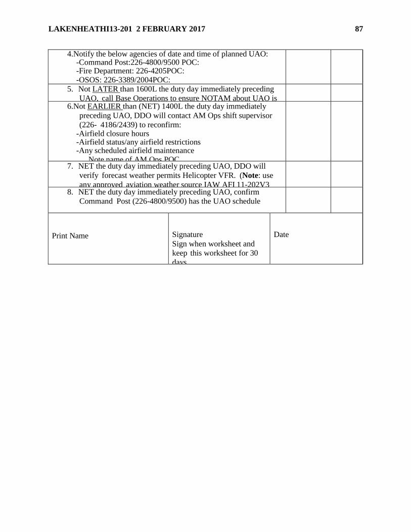
LAKENHEATHI13-201 2 FEBRUARY 2017 87
4.Notify the below agencies of date and time of planned UAO: -Command Post:226-4800/9500 POC: -Fire Department: 226-4205POC: -OSOS: 226-3389/2004POC:
5. Not LATER than 1600L the duty day immediately preceding
UAO, call Base Operations to ensure NOTAM about UAO is
posted.
6.Not EARLIER than (NET) 1400L the duty day immediately
preceding UAO, DDO will contact AM Ops shift supervisor
(226- 4186/2439) to reconfirm: -Airfield closure hours -Airfield status/any airfield restrictions -Any scheduled airfield maintenance
Note name of AM Ops POC
7. NET the duty day immediately preceding UAO, DDO will
verify forecast weather permits Helicopter VFR. (Note: use
any approved aviation weather source IAW AFI 11-202V3
para 2.3.1.2)
8. NET the duty day immediately preceding UAO, confirm
Command Post (226-4800/9500) has the UAO schedule
Print Name
Signature
Sign when worksheet and
keep this worksheet for 30
days.
Date
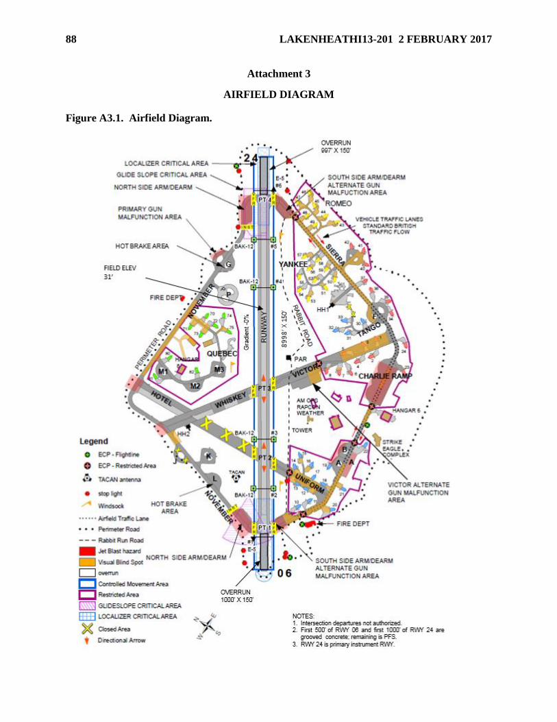
88 LAKENHEATHI13-201 2 FEBRUARY 2017
Attachment 3
AIRFIELD DIAGRAM
Figure A3.1. Airfield Diagram.
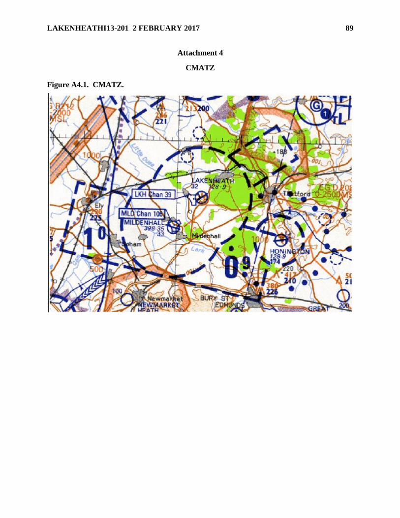
LAKENHEATHI13-201 2 FEBRUARY 2017 89
Attachment 4
CMATZ
Figure A4.1. CMATZ.
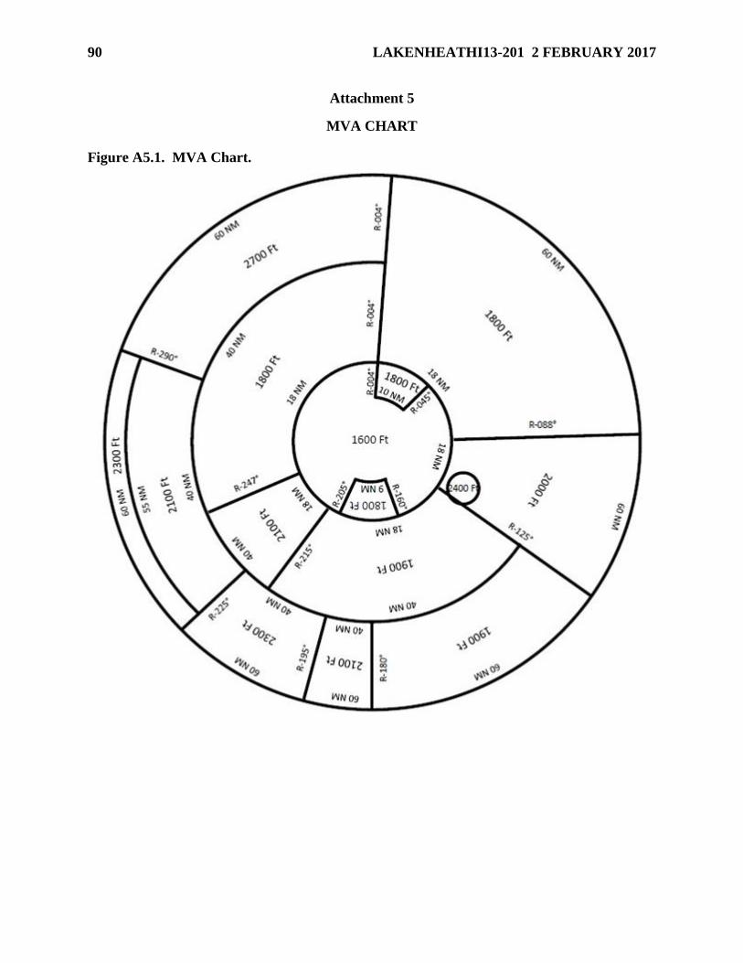
90 LAKENHEATHI13-201 2 FEBRUARY 2017
Attachment 5
MVA CHART
Figure A5.1. MVA Chart.
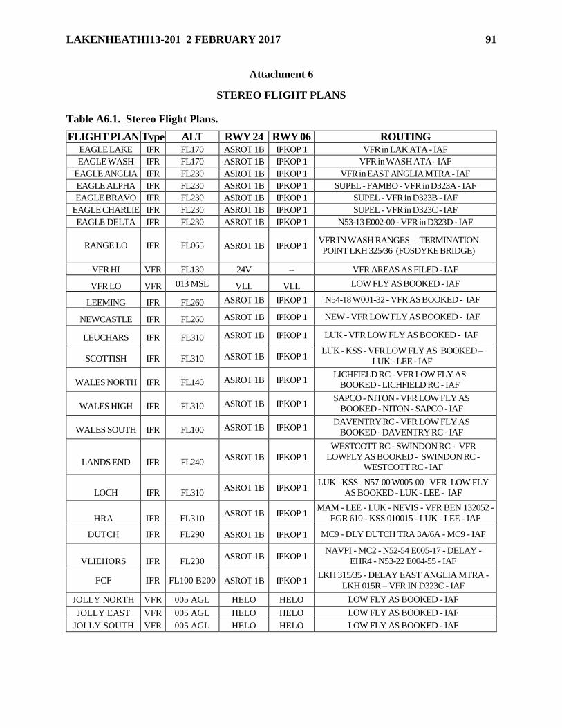
LAKENHEATHI13-201 2 FEBRUARY 2017 91
Attachment 6
STEREO FLIGHT PLANS
Table A6.1. Stereo Flight Plans.
FLIGHT PLAN Type ALT RWY 24 RWY 06 ROUTING EAGLE LAKE IFR FL170 ASROT 1B IPKOP 1 VFR in LAK ATA - IAF
EAGLE WASH IFR FL170 ASROT 1B IPKOP 1 VFR in WASH ATA - IAF
EAGLE ANGLIA IFR FL230 ASROT 1B IPKOP 1 VFR in EAST ANGLIA MTRA - IAF
EAGLE ALPHA IFR FL230 ASROT 1B IPKOP 1 SUPEL - FAMBO - VFR in D323A - IAF
EAGLE BRAVO IFR FL230 ASROT 1B IPKOP 1 SUPEL - VFR in D323B - IAF
EAGLE CHARLIE IFR FL230 ASROT 1B IPKOP 1 SUPEL - VFR in D323C - IAF
EAGLE DELTA IFR FL230 ASROT 1B IPKOP 1 N53-13 E002-00 - VFR in D323D - IAF
RANGE LO IFR FL065 ASROT 1B IPKOP 1 VFR IN WASH RANGES – TERMINATION
POINT LKH 325/36 (FOSDYKE BRIDGE)
VFR HI VFR FL130 24V -- VFR AREAS AS FILED - IAF
VFR LO VFR 013 MSL VLL VLL LOW FLY AS BOOKED - IAF
LEEMING IFR FL260 ASROT 1B IPKOP 1 N54-18 W001-32 - VFR AS BOOKED - IAF
NEWCASTLE IFR FL260 ASROT 1B IPKOP 1 NEW - VFR LOW FLY AS BOOKED - IAF
LEUCHARS IFR FL310 ASROT 1B IPKOP 1 LUK - VFR LOW FLY AS BOOKED - IAF
SCOTTISH IFR FL310 ASROT 1B IPKOP 1 LUK - KSS - VFR LOW FLY AS BOOKED –
LUK - LEE - IAF
WALES NORTH IFR FL140 ASROT 1B IPKOP 1 LICHFIELD RC - VFR LOW FLY AS
BOOKED - LICHFIELD RC - IAF
WALES HIGH IFR FL310 ASROT 1B IPKOP 1 SAPCO - NITON - VFR LOW FLY AS
BOOKED - NITON - SAPCO - IAF
WALES SOUTH IFR FL100 ASROT 1B IPKOP 1 DAVENTRY RC - VFR LOW FLY AS
BOOKED - DAVENTRY RC - IAF
LANDS END
IFR
FL240 ASROT 1B IPKOP 1
WESTCOTT RC - SWINDON RC - VFR
LOWFLY AS BOOKED - SWINDON RC -
WESTCOTT RC - IAF
LOCH
IFR
FL310 ASROT 1B IPKOP 1
LUK - KSS - N57-00 W005-00 - VFR LOW FLY
AS BOOKED - LUK - LEE - IAF
HRA
IFR
FL310 ASROT 1B IPKOP 1
MAM - LEE - LUK - NEVIS - VFR BEN 132052 -
EGR 610 - KSS 010015 - LUK - LEE - IAF
DUTCH IFR FL290 ASROT 1B IPKOP 1 MC9 - DLY DUTCH TRA 3A/6A - MC9 - IAF
VLIEHORS
IFR
FL230 ASROT 1B IPKOP 1
NAVPI - MC2 - N52-54 E005-17 - DELAY -
EHR4 - N53-22 E004-55 - IAF
FCF IFR FL100 B200 ASROT 1B IPKOP 1 LKH 315/35 - DELAY EAST ANGLIA MTRA -
LKH 015R – VFR IN D323C - IAF
JOLLY NORTH VFR 005 AGL HELO HELO LOW FLY AS BOOKED - IAF
JOLLY EAST VFR 005 AGL HELO HELO LOW FLY AS BOOKED - IAF
JOLLY SOUTH VFR 005 AGL HELO HELO LOW FLY AS BOOKED - IAF
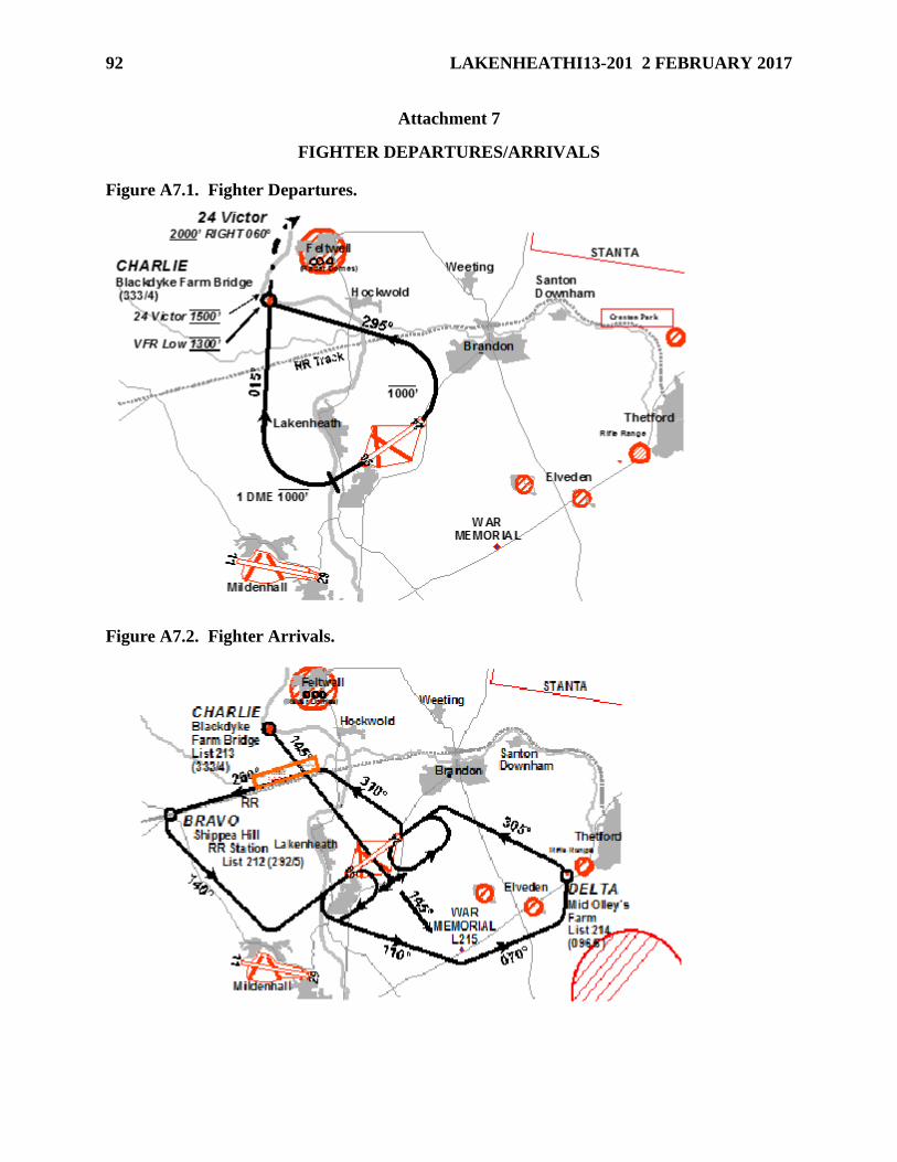
92 LAKENHEATHI13-201 2 FEBRUARY 2017
Attachment 7
FIGHTER DEPARTURES/ARRIVALS
Figure A7.1. Fighter Departures.
Figure A7.2. Fighter Arrivals.
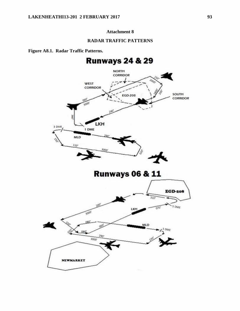
LAKENHEATHI13-201 2 FEBRUARY 2017 93
Attachment 8
RADAR TRAFFIC PATTERNS
Figure A8.1. Radar Traffic Patterns.

94 LAKENHEATHI13-201 2 FEBRUARY 2017
Attachment 9
HELICOPTER VFR DEPARTURES/ARRIVALS
Figure A9.1. Helicopter VFR Departures.
Figure A9.2. Helicopter VFR Arrivals.
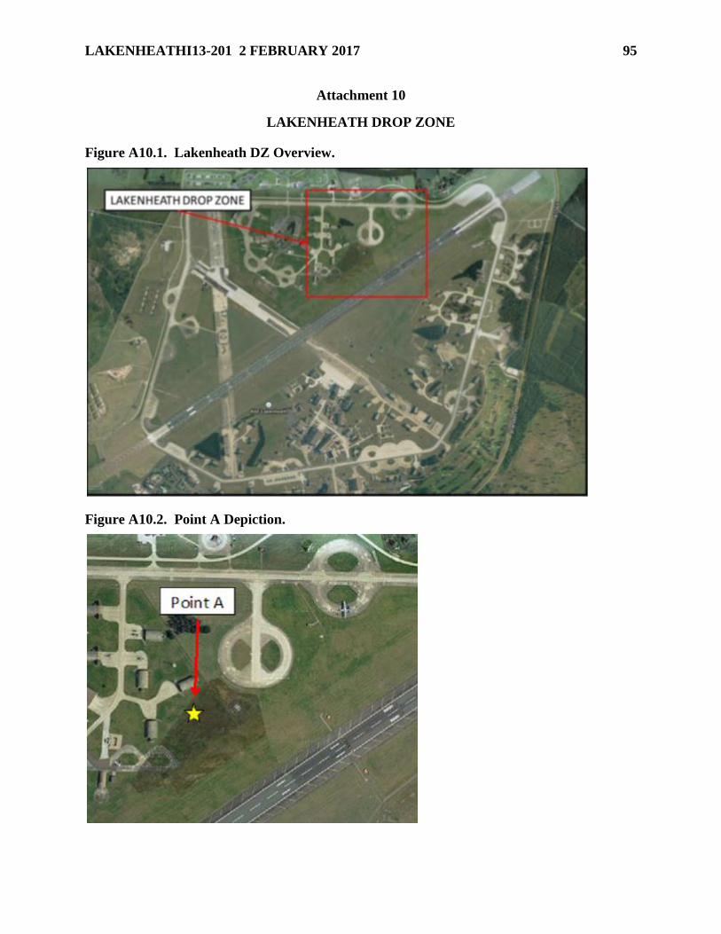
LAKENHEATHI13-201 2 FEBRUARY 2017 95
Attachment 10
LAKENHEATH DROP ZONE
Figure A10.1. Lakenheath DZ Overview.
Figure A10.2. Point A Depiction.
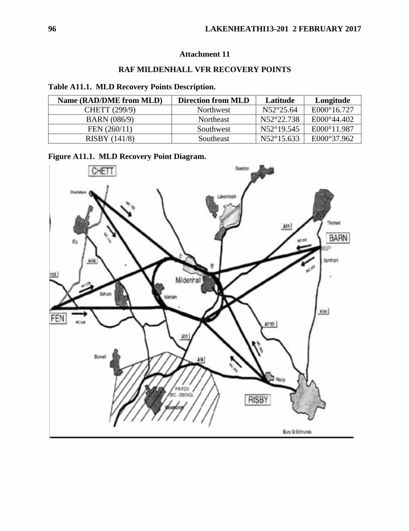
96 LAKENHEATHI13-201 2 FEBRUARY 2017
Attachment 11
RAF MILDENHALL VFR RECOVERY POINTS
Table A11.1. MLD Recovery Points Description.
Name (RAD/DME from MLD) Direction from MLD Latitude Longitude
CHETT (299/9) Northwest N52°25.64 E000°16.727
BARN (086/9) Northeast N52°22.738 E000°44.402
FEN (260/11) Southwest N52°19.545 E000°11.987
RISBY (141/8) Southeast N52°15.633 E000°37.962
Figure A11.1. MLD Recovery Point Diagram.