by: joseph martinez university of michigan supervisor: dave pushka, numi project 3q120-m quadrupole...
Post on 19-Dec-2015
217 views
TRANSCRIPT

By: Joseph Martinez
University of Michigan
Supervisor: Dave Pushka, NuMI Project
3Q120-M Quadrupole Magnet Transport

3Q120M Quadrupole Magnets
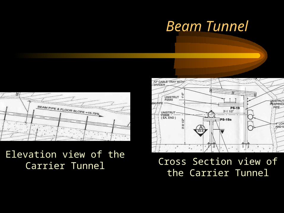
Beam Tunnel
Elevation view of the Carrier Tunnel Cross Section view of the Carrier
Tunnel
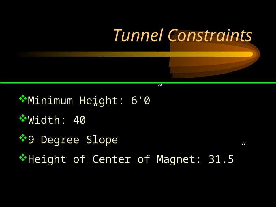
Tunnel Constraints
Minimum Height: 6’0”
Width: 40”
9 Degree Slope
Height of Center of Magnet: 31.5”
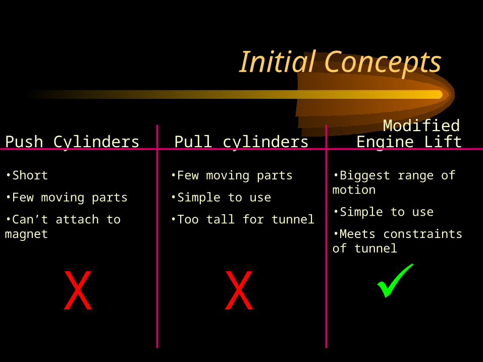
Initial Concepts
Push Cylinders Pull cylinders Engine Lift
•Short
•Few moving parts
•Can’t attach to magnet
X
•Few moving parts
•Simple to use
•Too tall for tunnel
X
•Biggest range of motion
•Simple to use
•Meets constraints of tunnel
Modified

Sketch of Design
Main Column
Main Beam
Rollers
Lug
Hydraulic CylinderCylinder Beam
Side Beams
Pivoting Arm

Lift with Magnet

Operation of Device
•Slide over the magnet from the side
•Attach to magnet
•Lower to carrying height
•Pull up incline
•Push around the stands
•Lower the magnet onto the stands
Magnet Fully Raised
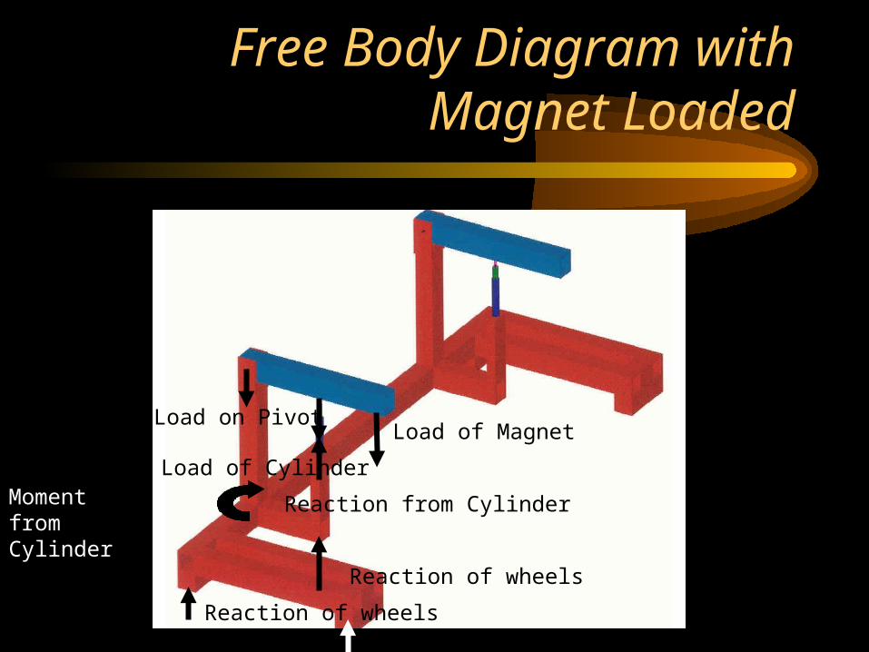
Free Body Diagram with Magnet Loaded
Load of MagnetLoad on Pivot
Reaction of wheels
Reaction of wheels
Reaction from Cylinder
Load of CylinderMoment from Cylinder
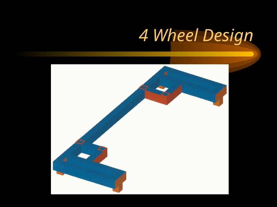
4 Wheel Design

6 Wheel Design

Base Stress Analysis(4-Wheel Design)
Max Stress: 7430 p.s.i.
Max Deflection: .0359”

Base Stress Analysis(6-Wheel Design)
Max Stress: 3690 p.s.i.
Max Deflection: .006”

Top Stress Analysis(With Supports)
Max Stress:7880 p.s.i.
Max Deflection: .0471”
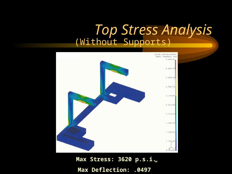
Top Stress Analysis(Without Supports)
Max Stress: 3620 p.s.i.
Max Deflection: .0497”
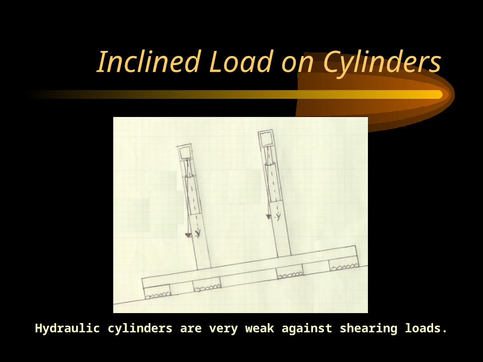
Inclined Load on Cylinders
Hydraulic cylinders are very weak against shearing loads.

Solution
Wire Rope attached from the pivoting beam to bottom lifting lug.
Load on Cylinder
Reaction ofWire Rope
Materials
2 - 5-ton capacity Hillman rollers and 4 - 3.75-ton capacity Hilman RollersBeam Dimensions: 6” x 4” x ½” A500 Structural Steel TubeColumn Dimensions: 4” x 4” x ½” A500 Structural Steel Tube2 - 5-ton capacity Hydraulic CylindersLength of Frame: 120”Height of Frame (pivoting arm parallel to ground): 53”Width of Frame: 40”
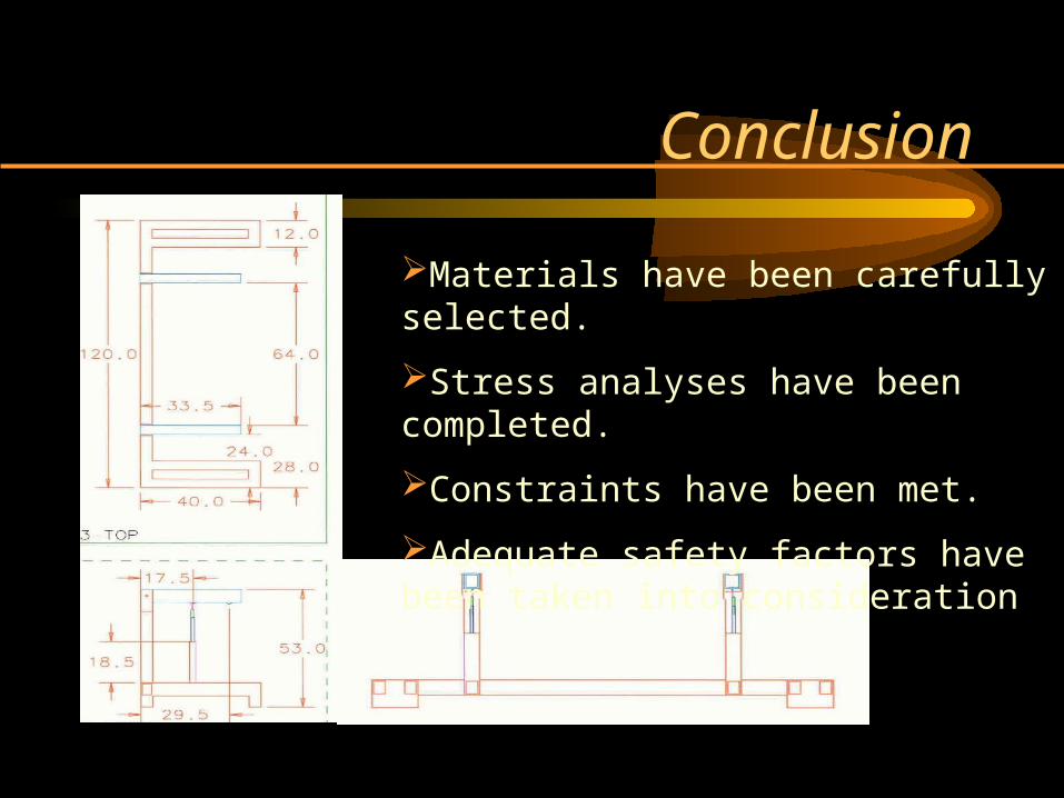
Conclusion
Materials have been carefully selected.
Stress analyses have been completed.
Constraints have been met.
Adequate safety factors have been taken into consideration
