bus-driven floorplanning hua xiang*, xiaoping tang +, martin d. f. wong* * univ. of illinois at...
TRANSCRIPT
Bus-Driven Floorplanning
Hua Xiang*, Xiaoping Tang+, Martin D. F. Wong*
* Univ. Of Illinois at Urbana-Champaign+ Cadence Design Systems Inc.
Floorplanning & Bus Planning Bus planning
An important issue for floorplanning in DSM Buses:
Different widths Go through several module blocks
The positions of module blocks heavily affect bus planning.

An Example
(a) A floorplan with 2 buses. (b) Neither bus can be assigned.
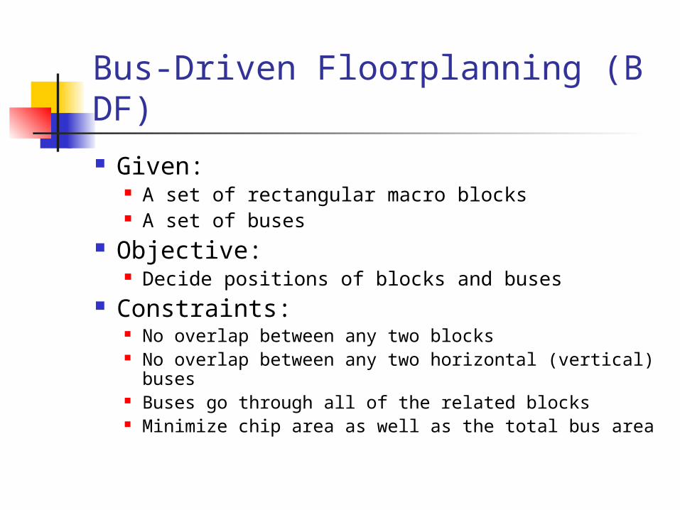
Bus-Driven Floorplanning (BDF) Given:
A set of rectangular macro blocks A set of buses
Objective: Decide positions of blocks and buses
Constraints: No overlap between any two blocks No overlap between any two horizontal (vertical)
buses Buses go through all of the related blocks Minimize chip area as well as the total bus area

Preliminary Sequence Pair
A pair of sequences of n elements representing a list of n blocks. Block position relationship
(… bi … bj … , … bi … bj …) (… bi … bj … , … bj … bi …) Bus representation < H/V , w , {b1, b2, … , bk} >
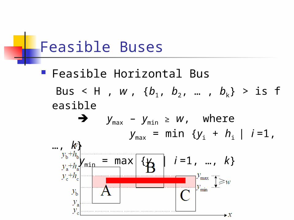
Feasible Buses
Feasible Horizontal Bus Bus < H , w , {b1, b2, … , bk} > is feasible
ymax – ymin ≥ w, where ymax = min {yi + hi | i =1, …, k} ymin = max {yi | i =1, …, k}

Necessary Condition for One Bus
(a) A horizontal bus
( … A … D … B … C … , … A … D … B … C … )
(b) A vertical bus( … A … C … B … , … B … C … A … )
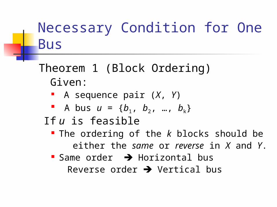
Necessary Condition for One Bus
Theorem 1 (Block Ordering) Given:
A sequence pair (X, Y) A bus u = {b1, b2, …, bk}
If u is feasible The ordering of the k blocks should be either the same or reverse in X and Y. Same order Horizontal bus Reverse order Vertical bus

Bus Ordering between Two Buses Given two horizontal buses: u = {a1, … , am} and v = {b1, … , bn} Let Su = {a1, … , am}, Sv = {b1, … , bn}. S = Su∪Sv and L = |S| ( L ≤ m + n ) Given a sequence pair (X, Y) = (… c1 … c2 … … cL … , … d1 … d2 … … dL …) where ci ∈S and di ∈S Subsequence pair: (X ’, Y ’) = ( c1 c2 … cL , d1 d2 … dL ) Let p[ci] = i and q[di] = i (i = 1, … , L)

Bus Ordering between Two Buses
Case 1 ; bus u is above bus v Bus Constraint
][][, bqbpSb u ][][, bqbpSb u
Two buses: {A, B, C} {D, E, F}SubSequence pair (D A E B F C , A D B E C F)

Bus Ordering between Two Buses
Case 2 ; bus u is below bus v Bus Constraint
][][, bqbpSb u ][][, bqbpSb u
Two buses: {A, B, C} {B, D, E}SubSequence pair (A D B C E , D A B E C)
Bus Ordering between Two Buses
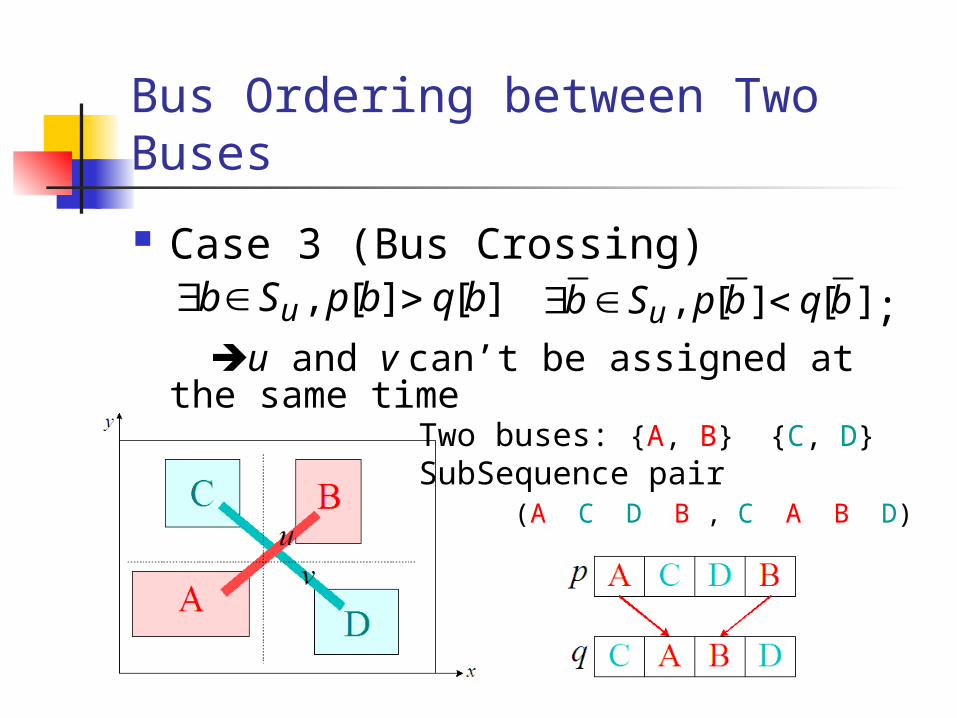
Case 3 (Bus Crossing) ; u and v can’t be assigned at the same
time
][][, bqbpSb u ][][, bqbpSb u
Two buses: {A, B} {C, D}SubSequence pair (A C D B , C A B D)

Bus Ordering between Two Buses
Case 4 No Bus Constraint
][][, bqbpSb u
Two buses: {A, B, C} {D, E}SubSequence pair (A D B E C , A D B E C)
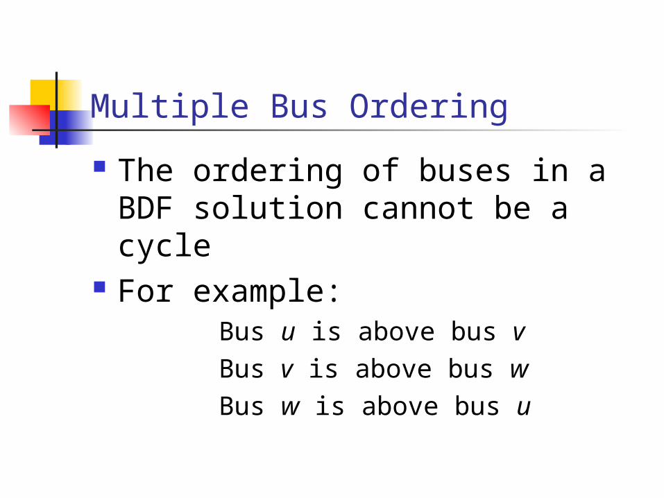
Multiple Bus Ordering The ordering of buses in a BDF
solution cannot be a cycle For example:
Bus u is above bus v Bus v is above bus w Bus w is above bus u
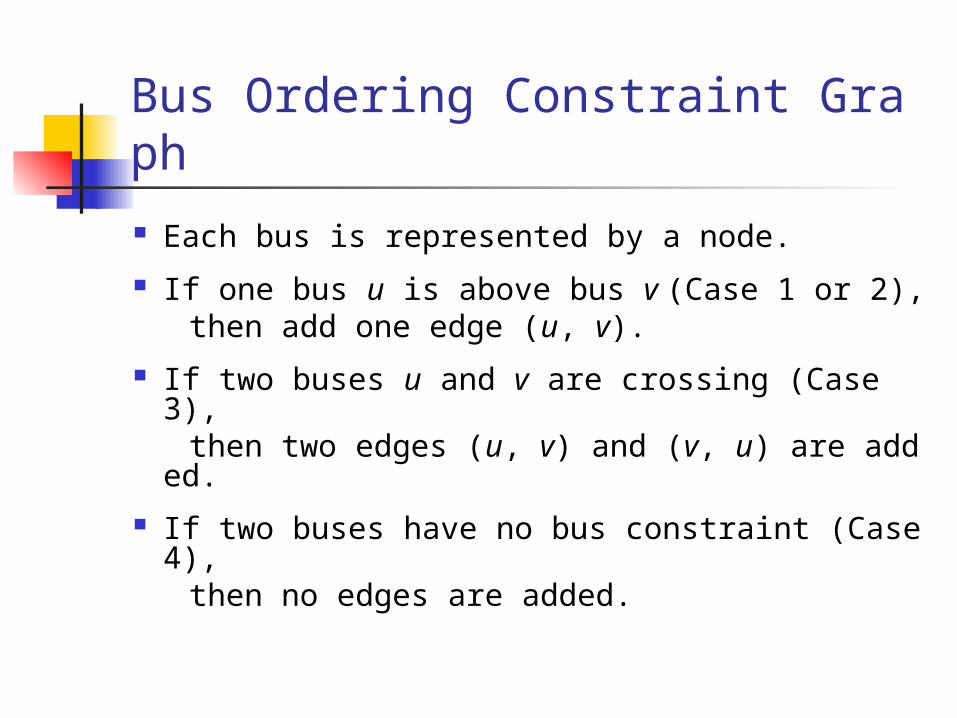
Bus Ordering Constraint Graph Each bus is represented by a node. If one bus u is above bus v (Case 1 or 2), then add one edge (u, v). If two buses u and v are crossing (Case 3), then two edges (u, v) and (v, u) are added. If two buses have no bus constraint (Case 4),
then no edges are added.
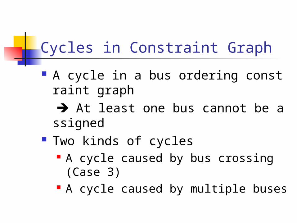
Cycles in Constraint Graph A cycle in a bus ordering constraint grap
h At least one bus cannot be assigned Two kinds of cycles
A cycle caused by bus crossing (Case 3) A cycle caused by multiple buses
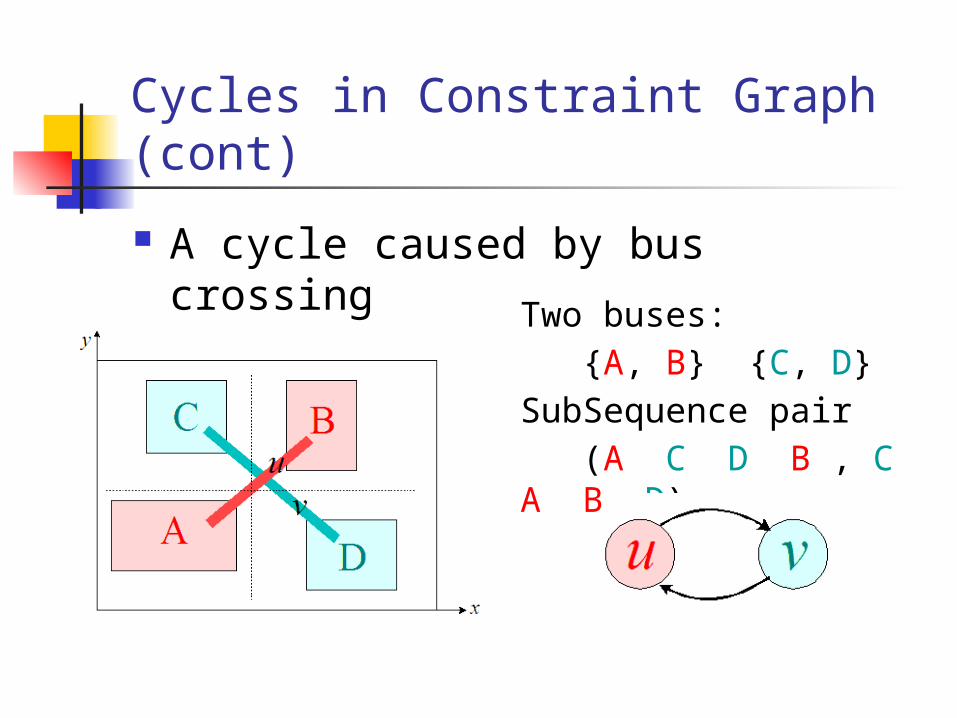
Cycles in Constraint Graph (cont)
A cycle caused by bus crossing
Two buses: {A, B} {C, D}SubSequence pair (A C D B , C A B D)

Cycles in Constraint Graph (cont)
A cycle caused by multiple busesThree buses: {A1, A2} {B1, B2} {C1, C2}Sequence pair ( A1 B1 B2 C1 C2 A2 , B1 A1 C1 B2 A2 C2 )

Cycles in Constraint Graph (cont)
Remove fewest nodes from a constraint graph The graph contains no cycles
It is proved to be an NP-Complete problem. A heuristic approach
If a node whose in-degree or out-degree is zero, then the node should not be removed. If all nodes whose in-degree and out-degree are
non-zero, remove the node with the max degree.

Node Removal in Constraint Graph
(a) A constraint graph with cycles. (b) Nodes a, e and d are good nodes and they are not
considered.

Node Removal in Constraint Graph
(b) Nodes a, e and d are good nodes and they are not
considered.
(c) Node c has the max degree and it is removed
from the graph.

Node Removal in Constraint Graph
(a) A constraint graph with cycles. (d) Nodes c and i are removed to break
cycles.

BDF Algorithm
Simulated Annealing Perturbation (Move) Cost Function Evaluation Algorithm

Perturbation (Move)
Swap Exchange two blocks in the first sequence Exchange two blocks in the second
sequence Take constant time
Rotation Exchange the width and height of a block No change to the sequence pair Take constant time

Cost Function Objective
Fit in all buses Minimize the chip area Minimize the total bus area
Cost Function
C : the chip areaB : the total bus areaM : the number of unassigned buses
MBCCost

Evaluation Algorithm
Transform a sequence pair to a BDF solution How to detect infeasible buses ?
Violate block ordering Discard the bus Bus nodes form cycles in a constraint graph Node Remov
al How to decide block positions ?
Longest Common Subsequence Computation (LCS) How to assign buses ?
Assign a bus if its related blocks have been processed Related blocks may have to move up/left to meet bus align
ment requirement
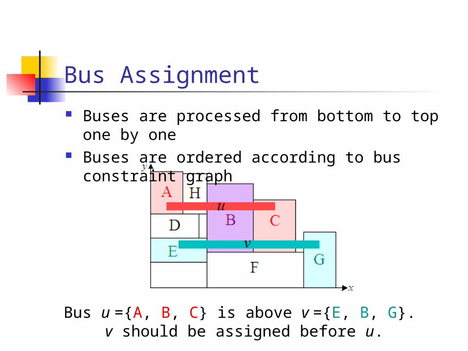
Bus Assignment
Buses are processed from bottom to top one by one
Buses are ordered according to bus constraint graph
Bus u ={A, B, C} is above v ={E, B, G}. v should be assigned before u.

Bus Assignment (cont) Block alignment for one bus <H, w, {b1,
…, bk}>
ymax = max {yi | i = 1, …, k}
yi = max (yi, ymax + w – hi)
Bus_Overlap
(a) Two buses overlap (b) No overlap between two buses

(b) Blocks appear interlaced.
(A D B E C, A D B E C)
Bus Assignment (cont) Cases for Bus_Overlap
Two buses have ordering constraint (Case 1 or 2), no Bus_Overlap
Two buses have no ordering constraint (Case 4), there are 3 cases
(a) Two buses share at least one block.
(c) Blocks appear non-interlaced.
(A B C D E, A B C D E)Bus_Overlap may happen for (a) and (b)

Evaluation Algorithm
Evaluation_BDF (seq_pair, buses){ 1. Feasible_Bus_Checking_Orientation
// Remove buses which cannot be assigned due to block ordering or// cycles in constraint graphs. At the same time, decide bus
orientation
2. Bus_Ordering//Sort buses according to below-above/left-right relationship
3. Modified_lcs_computation//Calculate the positions of blocks and buses
4. Cost_Calculation 5. Return cost
}

Soft Block Adjustment
Blocks on longest common subsequence paths decide the chip size.
Each time, one soft block on a longest common subsequence path is selected, and its width and height are adjusted.
Simulated Annealing is applied again to find a compact floorplan.

Soft Block Adjustment (cont) An example
Blocks B, D, E are on a critical path. E is selected and adjusted. The chip size is
reduced.

Experimental Results
Hardware: workstation (2.4GHz) with 1G memory Software: C++ Test files
MCNC benchmarks Industry designs Bus grid test files

Experimental Results (cont)
(a) MCNC benchmarks
File Blocks BusesPacking Results
Soft Block Adjustment
Time(s)Deadspac
eTime(s)
Deadspace
apte 9 5 11 4.11% 12 (+1) 0.72%
xeorx 10 6 12 3.88% 13 (+1) 0.95%
hp 11 14 28 5.02% 28 (+0) 0.62%
ami33-1 33 8 61 6.02% 62 (+1) 0.94%
ami33-2 33 18 81 6.10% 86 (+5) 1.27%
ami49-1 49 9 98 5.42%101 (+3)
0.85%
ami49-2 49 12 278 6.09%281 (+3)
0.84%
ami49-3 49 15 265 7.40%268 (+3)
1.09%

Experimental Results (cont)Ami49-2 (after soft-adjustment)
49 blocks, 12 busesBuses
{0, 5, 9, 12, 18}{1, 10, 21, 25}{2, 28, 33}{3, 19, 22, 26, 29, 34}{4, 23, 27}{5, 35, 30, 6}{32, 31, 17}{11, 14, 15, 32, 33}{12, 8, 14}{44, 43, 7}{0, 3}{2, 47}
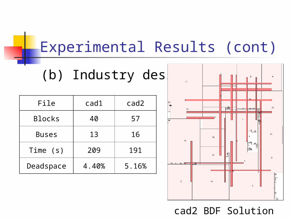
Experimental Results (cont)
(b) Industry designs
File cad1 cad2
Blocks 40 57
Buses 13 16
Time (s) 209 191
Deadspace 4.40% 5.16%
cad2 BDF Solution

Experimental Results (cont)
(c) Bus grid test files
File grid4 grid5 grid6 grid7
Blocks 16 25 36 49
Buses 8 10 12 14
Time (s) 1 23 103 150
Deadspace
0% 0% 0% 0%
Optimal BDF Solution for grid7

Conclusion
Analyze the relationship between bus ordering and sequence pair representation
Propose an algorithm for simultaneous floorplanning and bus planning using simulated annealing
Experimental results demonstrate its effectiveness and efficiency
