burning garbage and land disposal in rural · pdf fileburning garbage and land disposal in...
TRANSCRIPT

Burning Garbage and Land Disposal In Rural Alaska
A Publication for Small Alaskan Communities Considering Incineration and Energy Recovery
Prepared by:
State of Alaska
Alaska Energy Authority
Alaska Department of Environmental Conservation
May 2004

- 2 -
Burning Garbage and Land Disposal in Rural Alaska, a Publication for Small Alaskan Communities Considering Incineration and Energy Recovery was prepared and produced by the Alaska Energy Authority and the Alaska Department of Environmental Conservation.
This publication had help and support from the following contributors:
1. Alaska Energy Authority (AEA/AIDEA) supplied expertise and oversight in the production of this publication. AEA also contributed financial support for a Small Direct Waste Combustor Database 2000.
2. The authors are grateful for funding support from the U.S. Department of Energy's (USDOE) Pacific Regional Biomass Energy Program through grant #DE-FG51-02R021317. This support does not constitute an endorsement by USDOE of the publication's content.
3. University of Alaska, under RSA from AEA, developed raw data for the Small Direct Waste Combustor Database 2000.
4. Alaska Department of Environmental Conservation’s (ADEC) Solid Waste and Air Quality Programs provided input regarding compliance and permitting. Special thanks are given to Doug Buteyn and Leslie Simmons of the ADEC Solid Waste Program for their help in editing this publication and Bill Walker of the ADEC Air Quality Program for his assistance on air quality issues.
This publication can be accessed on-line at the following addresses:
Alaska Energy Authority http://www.aidea.org/aea.htm
Alaska Department of Environmental Conservation Division of Environmental Health Solid Waste Program http://www.state.ak.us/dec/eh/sw/index.htm
Prepared on May 2004 by:
-- Bert E. Emswiler MPH REHS, Alaska Department of Environmental Conservation -- Peter M. Crimp, Alaska Energy Authority

- 3 -
Table of Contents CHAPTER ONE: INTRODUCTION.......................................................................................................................5
CHAPTER TWO: HOW WASTE IS BURNED......................................................................................................7 A. COMPONENTS OF MUNICIPAL SOLID WASTE (COMMUNITY GARBAGE) .........................................................7 B. WASTE COMBUSTION.....................................................................................................................................8
1) Holding Time .............................................................................................................................................8 2) Temperature...............................................................................................................................................9 3) Turbulence .................................................................................................................................................9 4) Chemical Composition of the Waste ..........................................................................................................9
C. THE POLLUTANTS OF CONCERN ...................................................................................................................10 D. MANAGING WASTE COMBUSTION (BEST MANAGEMENT PRACTICES) ........................................................11
1) Site the Burning System ...........................................................................................................................11 2) Separate Non-Combustible Waste and Hazardous Waste .......................................................................11 3) Manage and monitor the combustion cycle for maximum combustion efficiency....................................11 4) Keep the Waste Dry .................................................................................................................................12 5) Remove ash when it is thoroughly cooled................................................................................................12
CHAPTER THREE: BURNING METHODS AND COMPONENTS ................................................................13 A. OPEN BURNING ............................................................................................................................................13
1) Open Burning on the Ground ..................................................................................................................13 2) Burn Cages ..............................................................................................................................................14 3) Burn Barrels ............................................................................................................................................15
B. INCINERATORS .............................................................................................................................................17 1) Burn Boxes...............................................................................................................................................18 2) Air Curtain Incineration ..........................................................................................................................19 3) Multiple-Chamber, Batch Starved Air Systems (TOS).............................................................................21
C. ENERGY RECOVERY .....................................................................................................................................23 1) Economics of Heat Recovery ...................................................................................................................23 2) Heat Recovery Incinerator Systems: An Example ...................................................................................25
CHAPTER FOUR: REGULATIONS - GUIDELINES TO SUCCESS...............................................................27 A. AIR QUALITY CONTROL REGULATIONS (18 AAC 50) ..................................................................................27
1) Requirements are Becoming Stricter .......................................................................................................27 2) Requirements for Open Burning ..............................................................................................................28 3) Requirements for Incineration .................................................................................................................28 4) Wastes That Should Not Be Burned .........................................................................................................29
B. SOLID WASTE MANAGEMENT REGULATIONS (18 AAC 60) .........................................................................31 1) Ash Disposal Requirements .....................................................................................................................31 2) Proposed Changes to the Regulations .....................................................................................................31 3) Wastes That Can and Cannot Be Disposed .............................................................................................32
CHAPTER FIVE: OTHER RESOURCES ............................................................................................................35
CHAPTER SIX: DEFINITIONS ............................................................................................................................37
APPENDIX A - CASE STUDY: BURN BOX - MANLEY HOT SPRINGS, ALASKA......................................39
APPENDIX B - CASE STUDY: THERMAL OXIDATION UNIT - EGEGIK, ALASKA ................................49
APPENDIX C – CASE STUDY: THERMAL OXIDATION UNIT - SKAGWAY, ALASKA..........................57
APPENDIX D – SMALL DIRECT WASTE COMBUSTOR DATABASE .........................................................67

- 4 -

- 5 -
Chapter One: Introduction
Burning household waste is a widespread practice in rural Alaska to reduce waste volume, decontaminate refuse, and make waste less attractive to animals. This guide is designed to be a resource for communities and others considering incineration as an element of their waste management program.
Burn systems range from inexpensive but more hazardous open burning to more effective but costly dual chamber batch starved air incinerators. Risks, benefits and costs of each combustion method should be compared to local and regional disposal options. Local options may include operating a disposal facility near the community where the waste was generated while regional options may include shipping waste to a more acceptable location for disposal. Some form of incineration may be a valid option for a community in which a raw garbage landfill cannot be properly located, operated, closed or monitored. This may be true in situations where water pollution, animal attraction, and other health and safety issues result from improper disposal of raw garbage. A landfill that accepts ash from incineration and other non-combustible wastes may be preferable to a raw garbage landfill in this case.
The publication focuses on direct combustion systems that treat up to 10 tons of municipal solid waste per day, the approximate waste stream of a community of 3,500. However, most of the systems discussed in this publication can be sized to accommodate small communities of less than 1,000. In Appendix A, B, and C, we provide case studies of incineration equipment that is currently in use in some Alaskan communities. In Appendix D we present a database of various manufacturers of incineration equipment.
This publication is not intended to promote the combustion of municipal garbage, nor does it endorse the vendors listed. The intention is to offer up a sense of what distinguishes acceptable from unacceptable burning practices. It is intended to also give a sense of why the burning of garbage may help decrease the complications related to disposing of raw garbage. Since a complete description of the legal and technical aspects of waste combustion is beyond the scope of this guide, we have provided a list of additional resources in Chapter 5. Please refer to the glossary in Chapter 6 for definitions of some of the terms used in this document.

- 6 -

- 7 -
Chapter Two: How Waste is Burned
Alaskans use a wide variety of combustion methods that range from less expensive open burning to more costly high temperature multiple chambered incinerators and thermal oxidation systems. Generally, the higher temperature combustion systems tend to be more expensive to purchase and maintain. However, these systems cause less pollution than do the less expensive and lower temperature open burning, burn barrel, burn cage and burn box methods. The next section explains why this is so.
A. Components of Municipal Solid Waste (Community Garbage)
Understanding waste combustion requires knowledge of the waste and how it is burned. Municipal solid waste contains both combustible (e.g. paper, plastic, wood, and food) and non-combustible (e.g. metal and glass) materials (Figure 1). Combustible wastes account for about
70% of municipal waste. Paper and cardboard alone make up around 40% of the total. Garbage averages about 5,000 BTUs per pound. For heating value comparison, dried spruce wood averages 8,100 BTUs per pound. Garbage also contains 20% to 40% water. The amount of water and non-combustibles in the waste reduces the burning efficiency (Figure 2).
2 1 %
5 1 %
7 %
2 1 %
M o i s t u r e
V o l a t i l eM a t t e r
F i x e dC a r b o n
G l a s s ,M e t a l ,A s h
3 8 %
7 %8 %8 %6 %
7 %
1 8 %
8 %
P a p e r &C a rd b o a rdG la ss
M e ta ls
P la s tic s
W o o d
F o o d W a ste s
V e g e ta tiv e
O th e r
Figure 1: Material composition of municipal solid waste.
Figure 2: Chemical composition of municipal solid waste.

- 8 -
B. Waste Combustion
Effective combustion produces ash that is inert and does not attract animals. Effective combustion also minimizes air pollution. In order to effectively burn garbage without producing air pollution, the following four items are needed:
• A design that gets air into the burning chamber, including beneath the burning waste (under fire air).
• A mechanical draft. Natural draft is unlikely to supply enough air and turbulent mixing in the high temperature region.
• Supplemental fuel. Supplemental fuel is needed for starting the burn and for burning the gases and smoke. Garbage does not generally have enough BTUs (especially under wet or cold conditions) to burn completely without supplemental fuel and mechanical draft.
• A method to retain heat inside the burning chamber. This is accomplished by using a refractory. A refractory is a heat insulating lining in a burn chamber. Normally, a refractory is made of brick. Incineration units without a refractory do not hold heat particularly well and develop low-temperature areas within the burning waste that will produce smoke.
Use of the four items mentioned above will promote more thorough burning of the waste and yield less polluted exhaust.
Whether it occurs in the open or in an incinerator, combustion proceeds in several stages. Water in the waste is driven out by heat produced from waste that is burning nearby. As the waste heats to between 250-1200 degrees Fahrenheit (°F), substances in the waste are converted into burnable gases. Smoke (visible emission) is produced in this temperature range. The longer waste is held within this 250-1200°F temperature range, the more smoke and contaminants are produced. The “start-up” and “cool-down” phases of a burn cycle contribute the most smoke. Open burning methods produce the most smoke because the waste and gases commonly do not reach temperatures above 1200° F. Effective combustion takes place when the burnable gases are heated beyond 1200°F and mixed with oxygen. Temperatures can reach 1800° F or higher during combustion.
The ash produced from combustion takes one of two forms. “Fly ash” is the finely ground particulate ash that is carried away into the air in the form of smoke. The ash that remains at the burn site after burning is complete is called "bottom ash". The amount of pollutants that are emitted into the air as fly ash and gases, or that are contained in the bottom ash depends on the completeness of the combustion process. All of the following factors work together to determine the completeness of combustion:
1) Holding Time
Combustion takes time. Holding time is the length of time needed to completely burn the waste. Reduced temperature, turbulence and BTU value, or an increase in moisture content will increase the holding time needed to completely burn waste.

- 9 -
2) Temperature
Higher combustion temperatures decrease the time needed to complete combustion. Generally, temperatures that exceed 1200°F with a holding time of 1-2 seconds will cause complete combustion. The result is that wastes will be consumed and visible emissions (smoke) and pollutant concentrations will be greatly reduced. The mixture of wastes that is typically found in household garbage is most effectively burned at higher temperatures. At high combustion temperatures it is not as important to keep non-burnable items out of the waste. Animal carcasses, medical waste, oily wastes and plastic packaging material can be safely burned only using higher temperature burning methods.
Proper burning temperatures are harder to reach and sustain when waste is burned in open piles. Wastes that are not burned effectively produce potentially harmful smoke. Therefore, the lower temperature burning methods are more likely to exceed air quality standards and produce air pollution. Also, the bottom ash is more likely to contain unburned waste that will attract animals. Fewer types of waste can be effectively burned using lower temperature methods so more separation of wastes is required prior to burning. The lower temperature methods also require more attention to operation in order to achieve an effective burn.
3) Turbulence
Waste must have enough oxygen around it to burn. Turbulent mixing of air and waste during burning provides the steady supply of oxygen needed to achieve the higher temperatures at which the waste can be completely consumed. The thorough mixing of air must take place in a high-temperature zone. The more advanced incineration designs provide effective turbulence in hot zones. The amount of mixing is affected by how air is injected into the incinerator and by the shape and size of the combustion chamber. The combustion chamber must be large enough to allow proper turbulence. It is important not to overfill an incinerator as this blocks airflow and minimizes the amount of mixing that occurs. Lower temperature burning methods (open burning) cannot make effective use of turbulence in hot zones. Even with turbulent mixing, low temperature combustion is ineffective because temperatures are not high enough to completely consume the waste.
4) Chemical Composition of the Waste
The goal of waste burning is to convert waste into inert bottom and fly ash with minimal creation of smoke and/or hazardous gases. The BTU value, moisture content, and chemical qualities of the waste affect the combustion process and the amount of contaminants that are released. The amount of metals and other chemicals that are contained in the fly ash or bottom ash depends on the amount of the various chemicals in the wastes that are burned and the completeness of combustion.
The separation of wastes that contain metals, chlorine and other contaminants will help to reduce hazardous products of combustion. Metal, glass and moisture do not burn effectively; they rob heat from the burning process, and therefore hinder proper combustion. A greater effort to separate out these items is required when using burning methods in which the proper temperatures, turbulent mixing and/or holding times cannot be achieved.

- 10 -
C. The Pollutants of Concern
The environmental and health issues associated with incineration are air pollution from gases, particulates (smoke) released during combustion, and contaminants in the bottom ash.
Pollutants in air emissions are regulated under the National Ambient Air Quality Standards set by the Environmental Protection Agency and include acid gases, trace metals, and trace organic compounds. These pollutants also include particulates, nitrogen oxides, and carbon monoxide. Acid gases such as hydrogen chloride and sulfur dioxide result from burning waste that has high levels of chlorine and sulfur (e.g., plastics and paper). Lead and cadmium (typically from batteries) are trace metals that are found in both fly ash and bottom ash.
The contaminant dioxin has drawn the greatest controversy because it is known to cause cancer at high doses. It is less clear what the health effect is of low doses of dioxin. Because dioxin is known to persist in the environment and to bioaccumulate in the food chain it is important to reduce production of and exposure to the chemical. Dioxin is formed in trace levels from the low-temperature combustion of raw garbage that contains organic compounds and chlorine. Household garbage contains sufficient amounts of both organic matter and chlorine compounds to form dioxin. Although separating out highly chlorinated wastes such as PVC pipe can help it is generally thought that the temperature of combustion is the main controlling factor in preventing dioxin formation.
Smoke (particulates) is also needed for the formation of dioxin to occur. The chemical reaction that creates dioxin cannot happen if there is no smoke. Any burning method that reduces the production of smoke will reduce the formation of dioxin. This is a desirable goal and should be considered in selecting a burning system. Since smoke forms in the temperature range of 250°F
to 1200°F, the best way to inhibit smoke formation is to burn at temperatures consistently above 1200°F. The longer the garbage smolders at less than 1200°F, the greater the amount of contaminants that will form. Smoke generated from burning garbage carries contaminants into the air from where they eventually settle on plants and water. Humans are exposed to the contaminants by breathing the smoke or by consuming foods that have been contaminated.
Open burning, burn cages, burn barrels and improperly designed and operated burn boxes all tend to produce more smoke and therefore more contaminants, including dioxin. It is safe to say that the open burning of raw garbage will produce far more dioxin than will the high temperature incineration of the same waste.
The USEPA has resources that may help to understand the dioxin risk. Fact sheets are available on-line that describe health effects, background exposures, and regulatory actions. The following web sites may be useful:
• http://www.epa.gov/ncea/pdfs/dioxin/dioxreass.htm - several fact sheets which explain the latest dioxin assessment information and control efforts
• http://www.epa.gov/ncea/pdfs/dioxin/part1and2.htm - review of the formation of dioxin like compounds (volume 2)

- 11 -
D. Managing Waste Combustion (Best Management Practices)
The following guidelines are considered best management practices for any method of burning garbage.
1) Site the Burning System
Wind speed, direction and distances from environmental receptors are factors to consider when locating any facility that burns garbage. A site for burning should be selected so that prevailing winds blow favorably away from the community, residences, and other potentially affected interests. In some areas temperature inversions may trap smoke close to the ground. When these conditions exist, burning should be avoided if residences will be located within the plume of smoke.
2) Separate Non-Combustible Waste and Hazardous Waste
As previously mentioned wastes such as metal and glass or which have a high moisture content do not burn effectively. These wastes rob heat from the burning process and work to decrease the efficiency of burning. Therefore, waste separation is more essential for lower temperature burning methods (open burn, burn cage, burn barrel, and burn box) than for higher temperature methods.
The regulations prohibit or restrict the burning of specific items. Please refer to Table 1 in Chapter 4 for a listing of the various wastes that are prohibited, conditionally prohibited or otherwise should not be burned.
3) Manage and monitor the combustion cycle for maximum combustion efficiency.
A burn cycle should be conducted to minimize the amount of time for the “start-up” and “cool-down” phases of the burn. The desired operating temperature should be attained as quickly as possible. The length of the start-up and cool-down phases of combustion are influenced by the
moisture content and BTU value of the waste, the amount of turbulence, and the chemical composition of the waste. With burning methods that tend to smolder, effective burning temperatures should be achieved before adding household waste to the fire. In order to facilitate a more rapid start-up phase, clean/dry wood and paper should be used. This material should be separated from the waste stream and made available at the site where the waste is burned. Using clean/dry wood and paper to achieve effective start-up temperatures is not necessary with more advanced incineration methods.
Figure 3: Incinerator emissions during start-up phase of operation.

- 12 -
4) Keep the Waste Dry
Household garbage is at least 20% water. Smoke production from burning garbage increases with the moisture content of the waste. Therefore, anything that can be done to decrease the amount of moisture in the waste will decrease the amount of smoke produced and increase the efficiency of the burn. There is also a cost saving to this, as the operational costs will decrease as moisture in the waste is reduced.
A waste management system that encourages users to store garbage in a way that keeps rain and snow out of the waste will help with this. Wastes
should be covered at residences, at transfer stations, and at the incineration/disposal site to reduce moisture. Wastes can be kept dry by placement inside a building once the garbage has been delivered to the disposal site.
5) Remove ash when it is thoroughly cooled.
Ash should be removed from a burn unit when it is no longer a danger to operators and will no longer cause unburned wastes in the disposal area to catch fire. Hot ashes or embers should never be put into the waste disposal cell. A fire in a disposal area should be avoided as a wildfire may result.
Figure 4: Village burn box. Note the dark smoke.

- 13 -
Chapter Three: Burning Methods and Components
The burning method used determines what can be burned. If operated correctly, the higher temperature methods can safely burn most of the items typically found in household garbage. The lower temperature open burning methods do not burn household wastes as completely and therefore cause more air pollution.
The various burning methods include open burning on the ground, burn cages, burn barrels, burn boxes, air curtain incineration, and multiple chambered incineration systems. Each method is discussed separately in the following sections.
A. Open Burning
“Open burning” means the burning of a material that results in the products of combustion being emitted directly into the air without passing through a smoke stack. Open burning includes burning garbage directly on the ground, in burn cages, and in burn barrels. Open burning is the least effective and most hazardous form of combustion. Unless closely managed, an open burn cannot achieve the temperatures needed to completely burn many components of municipal garbage. This allows the formation of potentially hazardous materials and renders ash that is more attractive to animals and more likely to cause surface and groundwater pollution at landfills. However, open burning is also the least expensive way to burn municipal solid waste, which is why it has been commonly used in Alaska.
The lower temperature burning methods rely more heavily on proper operation to reach effective burning temperatures. Proper operating conditions often are not accomplished due to the factors discussed earlier (see Chapter 2, Waste Combustion): holding time, temperature, turbulence, and the chemical composition of the waste.
It is the policy of the Alaska Department of Environmental Conservation (ADEC) to eliminate, minimize, limit or control open burning as needed and to encourage other methods of disposal or incineration where possible.
1) Open Burning on the Ground
Figure 5: Open burning of municipal garbage on the ground.

- 14 -
Many small rural communities in Alaska practice this method, but open burning on the ground using wet garbage as a fuel source does not work well. In general, the only items that can acceptably be burned in open fires on the ground are pallets and other similar dry uncontaminated wood and cardboard.
2) Burn Cages
Figure 6: Burn cage burning municipal garbage in rural Alaska.
A burn cage is a simple and inexpensive way to make an open burn more effective. It makes the following improvements over open burning on the ground:
1. As pictured above, the burn cage exposes the waste to natural draft on all surfaces including the bottom. This allows air to access the waste and promotes more efficient combustion throughout the burning period.
2. It limits the size of the waste pile thereby reducing the potential for smoldering of waste not exposed to air inside the pile.
3. It contains the burning within a specific location reducing the chance of the burn spreading to other waste disposal areas or surrounding vegetation.
The burn cage pictured above is a 12-foot long by 8-foot wide by 6-foot high rectangular frame (3 sections of which are 4-foot long) made of 3-inch by 2-inch double square tubing. Expanded metal grating covers the entire structure. The top is hinged in order to allow access and emptying of incomplete products of combustion. Metal plates welded to the bottom fit the forks of a forklift and allow the unit to be lifted so that ash can be removed from the ground and/or the unit can be easily re-positioned.
Proper operation involves loading the burn cage to about half of its capacity and then igniting the waste. Combustion air is drawn from all sides and the fuel is consumed much like that of an open burn, except more efficiently as more air is available. These units rely on natural draft, not a fan, to provide combustion air and do not require power or a motor to operate. The length of the burn cycle is dependent upon the amount and type of waste that is burned.

- 15 -
Although this form of burning is an improvement over uncontained open burning on the ground, there is still a good chance that insufficient turbulence and low burning temperatures will produce smoke and incomplete combustion products. The process may not consume large and frozen masses of waste and partly burned food wastes may still attract animals.
A common problem in using a burn cage is overfilling the unit. This decreases combustion efficiency and causes smoldering. Non-combustible items, hazardous wastes, and wastes that will smolder or produce smoke or odors should be separated out prior to burning. This method is an effective way to burn clean, dry wood, paper and other wastes that ignite and burn cleanly without smoke.
Burn cages can be built locally using existing resources. However, units can also be precut and shipped for assembly on site. Plans for burn cages may be obtained by contacting Alaska Native Tribal Health Consortium, Environmental Health and Engineering Branch in Anchorage, Alaska at 907-729-3600.
3) Burn Barrels
Burn barrels have been used extensively at Alaska residences. These devices are essentially 55-gallon drums that are modified with passive under-fire draft. Some have a stack and spark arrestor screen (see Figure 7). Some do not have a stack (see Figure 8).
Burn barrels operate at low temperatures (400°F to 500°F) and generally burn wet garbage, resulting in the incomplete combustion of the waste and the production of smoke. Burning materials such as plastics, asphalt, and rubber generates hazardous air pollutants. This may be a health threat and a nuisance for nearby residents. Burn barrels often emit acid vapors, carcinogenic tars, and "heavy metals" as well as unhealthful levels of carbon monoxide and particulates (smoke) when burning non-separated household garbage. For these reasons, the Alaska Department of Environmental Conservation discourages property owners from using burn barrels to burn household garbage.
Generally, the materials that can be burned effectively in a burn barrel include dry leaves, plant clippings, paper, cardboard and clean untreated wood (see Figure 9).
The closer one stands to the burn barrel, the more harmful chemicals one inhales. Burn barrels should not be used in close proximity to homes or areas where people can be exposed to the smoke. Burn barrels and burn piles can also lead to uncontrolled fires unless the following precautionary steps are taken:
• Clear all combustible materials and vegetation within 10 feet of the burn barrel;
• Place a metal mesh screen (spark arrestor) over the top of the burn barrel. The openings should be 1/2 inch or smaller.
• Place your burn barrel on concrete blocks and drill some small holes in the bottom to allow rainwater to drain.
• Don't start your fire unless you are prepared to monitor it until it is completely out.

- 16 -
• Check with your local fire department for burn barrel regulations and permits.
Figure 7: Burn barrel with stack and spark arrestor.
Figure 8: Example of a home burn barrel.

- 17 -
Figure 9: Burn barrel in Figure 8 burning paper, cardboard, and some plastic packaging material (no
food waste, cans, or glass).
B. Incinerators
Many waste incineration systems are used in Alaska. Appendix D provides information about small incineration systems that are in use in Alaska and contact information for commercial vendors of incinerators.
Incinerators burn waste at higher temperatures than open burn methods. Incinerators rely on engineered designs to achieve the higher temperatures that reduce smoke emissions and contaminant formation when burning garbage. With the higher temperature burning methods, smoke can be prevented with less attention to operation.
Most of the incineration systems described in this section are modular. Modular incinerators are manufactured in a shop off-site and installed at the place they are used. Site-built incinerators are generally larger, with capacities of over 500 tons per day. The largest municipal waste incineration system in the state is located in Juneau and includes two modular Consumat units with a total capacity of 72 tons per day.
Incinerators are often described based on the amount of combustion air that is provided to the system. Starved air systems contain at least two chambers. The primary chamber receives less than the amount of air needed to achieve full combustion. Gases from this incomplete combustion then pass into the second chamber where sufficient air is brought in for full combustion. Excess air systems are designed to introduce more than enough air (usually 50% more than the theoretical amount of air needed) into the primary chamber to allow complete combustion of waste.
Incinerators can also be described as either batch or continuous feed systems, according to how the waste is fed into and processed by the system.

- 18 -
1) Burn Boxes
Burn box being emptied into landfill.
Burn boxes are generally considered to be a modification to open burning because air is usually supplied passively and the waste is burned without supplied fuel or turbulent mixing. However, because these devices are usually fitted with a smokestack they are regulated as incinerators. Burn boxes are the least expensive incinerators in use, which is why they have received much attention in rural Alaska. They are single-chambered units. Waste is placed on grates inside the upper half of the unit. Ash falls through the grates during and after burning. Ash is cleaned from the lower half of the unit when a sufficient amount has accumulated.
Burn boxes usually rely on natural draft, not a fan, to provide combustion air and generally do not require power or a motor to operate. Some manufacturers, however, do produce units with blowers that provide for a forced air operation. The units with blowers tend to be more effective at burning garbage. However, these units require externally supplied power (through a generator or local power source) to operate the fan.
Burn boxes are the least effective form of incinerator and will exceed air quality standards if not operated carefully. Inert wastes such as metal and glass do not burn well and will rob heat from the combustion process, thereby creating a lower temperature burn. These wastes should be separated prior to burning and recycled, landfilled directly, or transshipped to another facility. Also, the burn cycle should be started using clean, dry wood or cardboard to reach operating temperatures prior to charging the unit with garbage. Large frozen masses of garbage or waste containing a high water content will not burn well with a burn box especially during cold winter conditions. Therefore, attention should be placed on minimizing the moisture content of the waste to be burned.
The Dot Lake burn box (Figure 10), consists of a cylindrical steel tank with an exhaust stack mounted on a skid platform made from an old dump truck bed and steel plating. The chamber inside the tank is divided into lower and upper sections by a rack that receives waste through a steel door. After up to 3 cubic yards of waste are loaded into the upper section, the maintenance worker ignites the waste with a match. Combustion air is drawn in from side air inlets, and the
Figure 10: The Dot Lake burn box.

- 19 -
fuel is consumed much like a wood stove from front to rear. A burn cycle (excluding the “cool-down” phase) takes several hours. Depending on the amount of use, ash is removed every three months or whenever the lower section is 30% full. Hinges on the rear of the unit allow it to be tipped by a jack and ash is manually pushed out from the front through a hinged opening in the back. Other than small amounts of used oil for start-up, the unit does not require supplementary fuel.
Burn boxes are or have been in use in Alakanuk, Aleknagkik, Ambler, Chenega Bay, Dot Lake, Elim, Goodnews Bay, Hughes, Kobuk, Manley Hot Springs, Marshall, Mountain Village, Nanwalek, Noatak, Pedro Bay and Tanacross. The current cost of a unit is around $12,000 but can be less if salvageable materials are available for local fabrication. Please refer to the Manley Hot Springs case study in Appendix A of this publication for more information on burn boxes.
2) Air Curtain Incineration
Air curtain incineration provides a more advanced form of combustion over open burning and burn boxes. Air curtain incineration operates by forcefully projecting a thin curtain of air at high velocity across an open chamber or pit in which burning occurs. This high-speed curtain of air helps these systems achieve the high temperatures and turbulence needed to burn waste completely. Incinerators of this type can be constructed above or below ground and with or without refractory walls and floor. All air curtain systems require externally supplied electrical power to drive the air curtain. This is provided through a generator or electrical power to the site.
Air curtain incinerators are not perfect systems. Even though ample turbulence is provided, the burn is not confined to a high-temperature region maintained by a fuel with a high BTU value. This means that cold areas exist within the burn and will form smoke. This is especially true during the start-up phase of the burn cycle when the turbulence will blow ash and smoke from the unit. This effect is minimized in the vertical column air curtain device that is described below.
The length of the burn cycle, including start-up and burn down, is dependent upon the amount, the moisture content, and the BTU value of the waste that is burned.
Three basic variations of the air curtain incinerator exist. One unit operates by blowing air into a pit (Figure 11). Another device has a refractory-lined, horizontal primary chamber into which the curtain of air is blown (Figure 12). These units have the advantage of being mobile and can be taken from site to site, but because they do not have retention chambers, smoke discharges directly from the unit into the air. These systems are used in other states to burn land clearing wastes and demolition debris. They have had limited use burning municipal waste in this country because of the difficulties in meeting air quality standards, especially during the start-up phase of the burn.

- 20 -
Figure 12: Horizontal above ground air curtain incinerator
during start-up (note 100% opacity).
A third type of air curtain incineration is called Vertical Column Air Curtain Incineration (Figure 13). Vertical Column Air Curtain Incineration has markedly improved burning qualities compared to the open burning and incineration methods previously discussed (including the other air curtain devices). It is one of the least costly of the better incineration methods.
A vertical column air curtain incinerator operates in a vertical column of air, in which smoke is returned from an upper retention chamber to the lower primary chamber using gravity and counter current draft.
Figure 13: Vertical Air Curtain Incinerator
Smoke is re-burned when it is convected back to the primary chamber. This process reduces smoke emissions and makes this system more acceptable for burning garbage and other municipal wastes. The air curtain provides active turbulent mixing of air into the waste, which increases the temperature. It takes approximately 10 minutes to reach operating temperatures during which time the unit will likely exceed air quality opacity standards. However, the waste will burn cleanly without smoke once operating temperatures are reached. Temperatures can
Figure 11: Pit air curtain incinerator.

- 21 -
reach as high as 2,000 oF during combustion, which leaves cans that easily crumble and ash that is not attractive to animals. Bottom ash is easily removed through access doors in the primary chamber.
The vertical column air curtain incinerator uses externally supplied fuel oil or propane to ignite the waste in the lower (primary) chamber. Once the waste is ignited an overfire air system (the air curtain) is activated and the externally supplied fuel is turned off. This provides a cost saving compared to the more advanced incineration systems that require supplemental fuel during the entire burning process.
The unit is not mobile and has not been used in Alaska for municipal use. Questions remain regarding the combustion efficiency of these units in harsh cold and wet Alaskan climates and to the extent non-combustible wastes need to be separated out prior to burning. On the positive side, vertical column air curtain incinerators have been used to burn municipal garbage in Colorado and California and have had extensive use in other countries. The total cost for these units will vary depending upon size and transportation costs.
3) Multiple-Chamber, Batch Starved Air Systems (TOS)
Over the last decade, a number of Alaskan communities have installed dual-chamber, batch-feed, starved air incinerators, variously called “thermal waste oxidizers” (Eco Waste Solutions Inc.), “thermal oxidation systems (TOS)” (Entech Inc.), “batch oxidation systems (BOS)” (Enerwaste International Corp.), or simply ”G Series” (Therm Tec Inc.) and “CA Series” (ACS Inc.) systems.
Figure 14: Thermal Oxidation System. Note Primary Chamber (left) and Secondary Chamber (right)
This method is generally considered to have the highest potential burning qualities of all of the incinerators and open burning methods mentioned. This method is most likely to prevent contamination to both air and land and to meet air quality standards. Problems with animal attraction to the ash are eliminated with this method. The main features of this type of incinerator are:
• Batch operation allows greater control of air and temperature throughout the process.
• Air turbulence is reduced in the primary chamber so fewer particulates are released from the stack.
• A wide range of waste types can be handled. Larger quantities of non-combustible waste (i.e. metal and glass), waste with higher moisture content and other wastes can be burned with this method.

- 22 -
• Externally supplied fuel oil and electricity are needed.
Dual-chamber starved air systems currently operate or have operated in Barrow, Cordova, Chignik Lagoon, Egegik, Eielson AFB, English Bay, Fort Yukon, Kodiak, Kotzebue, Nome, Red Dog Mine, and Skagway.
As shown in Appendix D, there is a wide range in both capacity and costs. These systems can handle from 0.01 to 1 ton of waste per hour including burning and cooling time. The cost for systems shipped from Anchorage ranges from around $25,000 to $600,000, while the shipping weight ranges from 2 to 100 tons. Supplemental fuel usage varies from 40 to 116 gallons per batch although many vendors said they could not give a reasonable estimate. Waste loading and ash removal are manual processes for smaller systems but may be automated for larger systems. All of the vendors report that their systems are capable of energy recovery.
Detailed descriptions of the systems operating in Egegik and Skagway, including installation and operating costs, are given in Appendix B and Appendix C, respectively.
Figure 15: Thermal Oxidation System

- 23 -
Figure 16: Thermal Oxidation System – Skagway, Alaska Primary Chamber Showing Ash After Burn-Down
C. Energy Recovery
As described previously, municipal solid waste contains a large amount of combustible paper, wood and other organic material. One attractive aspect of waste combustion is its potential for energy recovery.
Burning solid waste to produce electrical energy is common in other states and countries. Within the size range of incinerators that this publication addresses and the relatively small volumes of municipal solid waste that are available for burning, generating electricity by burning waste may not be practical. However, recovering heat energy in the form of hot water or steam may be a practical and feasible alternative.
1) Economics of Heat Recovery
Heat recovery from diesel generator cooling systems is common in rural Alaskan communities. In these systems, hot water is pumped from the power plant through insulated steel arctic pipe to one or more community facilities, often the school or water treatment plant. In the facility’s mechanical room, the heat energy in the hot water from the power plant is transferred to the facility’s heating system upstream of the boiler. The boiler does not operate unless the facility needs more heat than is supplied by the power plant.
- 24 -
Heat recovery from waste incinerators can be accomplished in much the same way and is often considered as an approach for reducing waste management costs. The feasibility of recovering heat from an incinerator depends on a number of site-specific factors including the following:
• the type and amount of waste that is burned;
• the type of incinerator that is used;
• the amount and cost of any supplementary fuel required to burn the waste;
• the distance between the incinerator and the facilities to be heated;
• the amount of heat the facilities can use at any given time compared with the amount that is available;
• the presence of an existing hot water piping system; and
• the cost of retrofitting the facilities to use the recovered heat.
In general, for heat energy recovery to be economically feasible, large quantities of waste need to be burned near the locations where the heat is needed. Therefore, a major concern is locating the incinerator as close as possible to the facilities that will use the recovered heat. In general, increasing the distance the hot water has to travel also increases the cost of the insulated piping, the amount of energy required to pump the water, and the amount of heat that is lost in transit. The cost of arctic pipe including installation is estimated at $50 per foot. So, every additional 10 feet of pipe adds $500 to the price of the system.
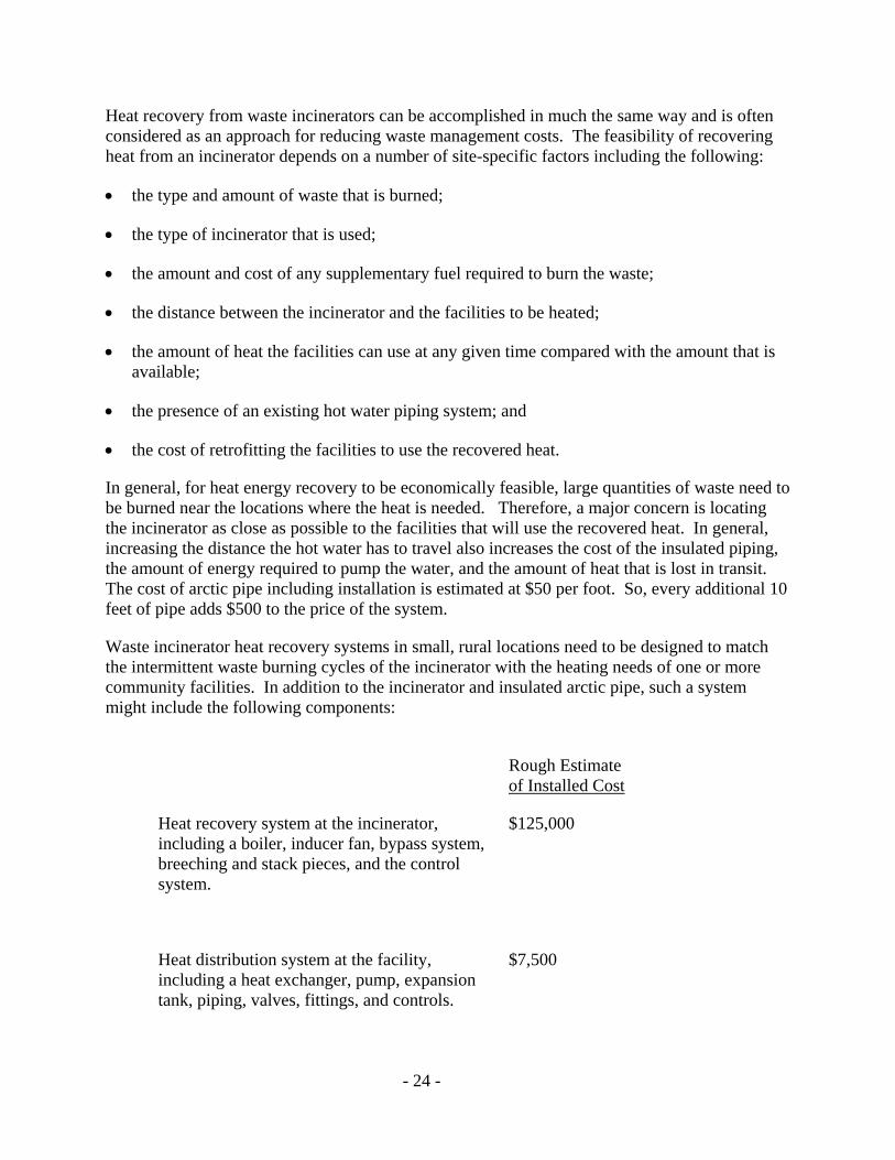
Waste incinerator heat recovery systems in small, rural locations need to be designed to match the intermittent waste burning cycles of the incinerator with the heating needs of one or more community facilities. In addition to the incinerator and insulated arctic pipe, such a system might include the following components:
Rough Estimate of Installed Cost
Heat recovery system at the incinerator, including a boiler, inducer fan, bypass system, breeching and stack pieces, and the control system.
$125,000
Heat distribution system at the facility, including a heat exchanger, pump, expansion tank, piping, valves, fittings, and controls.
$7,500

- 25 -
Including the cost of the engineering design (15%) and a contingency for other costs (10%), the estimated total cost of the system is approximately $165,600.
Operation and maintenance (O&M) requirements for a heat recovery system include labor costs for general maintenance and periodic cleaning of the fire tubes, the electrical power to run the circulating pumps, the cost of replacement parts, and the cost of rebuilding the heat exchangers every 10 years or so.
Similar to other waste management options, heat recovery should be assessed within a solid waste management planning process. The first step in the planning process should be a quick assessment of the feasibility and cost savings potential of a heat recovery system. The following is presented as an example of this process.
Unsorted municipal solid waste contains around 5,000 BTUs per pound, while #2 fuel oil contains 138,000 BTUs per gallon. The combustion efficiency of a typical incinerator is about 50%, while the efficiency of a boiler is about 70%. That means that 50% of the BTUs in the waste and supplemental fuel oil will be captured by the heat recovery system and 70% of the recovered heat energy will be transferred to the water in the boiler. Therefore, burning 3 tons of waste and 55 gallons of supplementary heating oil releases 37.6 million BTUs of heat energy, of which 13.2 million BTUs is transferred to the water in the boiler. If 150 batches of waste were burned in a year (about 3 loads per week), the total annual heat recovery would be approximately 1,973 million BTUs. Assuming that 75% of this annual heat can be used to replace heat produced from a 70% efficient oil-fired boiler at the water treatment plant, the heat recovery system would save around 15,300 gallons of fuel oil each year. Assuming fuel oil costs $1.50 per gallon, the value of the recovered heat would be approximately $23,000 per year. Assuming O&M costs of $8,000 for power, labor, and parts, the net value of the recovered heat energy is around $15,000 per year.
Using the estimated cost to install the heat recovery system ($165,625) and assuming that 600 feet of insulated piping is needed ($30,000), the total cost of the system (not including the incinerator) is about $196,000. Dividing the total cost ($196,000) by the estimated annual savings ($15,000) indicates that the installation cost will be recovered in about 13 years.
2) Heat Recovery Incinerator Systems: An Example
While there are no heat recovery incinerators in operation in rural Alaska, the Fairbanks Memorial Hospital operated a small incinerator equipped with heat recovery equipment from 1989 to 2001. Although the hospital chose to remove their incinerator due to changes in medical waste incineration regulations, the engineering staff was satisfied with the performance of the system and anticipates higher waste management and heating costs following its removal.
The Hospital’s Therm-Tec model AR-45 incinerator burned about 2,500 lbs. per day of medical, cafeteria, office, and packing waste on a continuous basis during one 14-hour shift per day. Every 10 minutes a hydraulic ram pushed a 70-pound load of waste into a primary chamber, where it was burned under starved air conditions. Gas from the primary chamber then entered the secondary chamber, where it was burned with supplementary fuel under excess air

- 26 -
conditions. Exhaust gas then passed through a heat recovery boiler that produced approximately 1.8 million BTUs per hour (mmBh) in the form of steam. A stack damper was designed to open automatically and route the exhaust gas through an emergency bypass stack if heat was not required or the boiler was not functioning properly. The steam produced from the burning waste, and about 120,000 gallons per year of #2 fuel oil, were used to heat the hospital and sterilize medical instruments. Bottom ash from the incinerator was automatically quenched in water and conveyed to an outside bin, where it was picked up and hauled to the landfill.
According to the hospital maintenance director, daily maintenance required 1-1.5 hours. Tasks included cleaning the debris from the chute between the primary chamber and the ash quench and clearing the primary air inlet tubes. Every three months, the incinerator was shut down for 2-3 days to clean out the boiler fire tubes, while twice per year two additional days were required for stack clean out. Annual maintenance required 1-2 weeks of down time while operators assessed and patched the firebrick as necessary, removed slag from the air tubes in the secondary chamber, and pulled out the hydraulic rams for lubrication and inspection.

- 27 -
Chapter Four: Regulations - Guidelines to Success
Communities that include waste combustion as part of their solid waste management system need to be familiar with the requirements of two sets of regulations: the Air Quality Control regulations (18 AAC 50) and the Solid Waste Management regulations (18 AAC 60). The air quality regulations cover the standards for limiting air pollution. The solid waste regulations cover the standards for disposing of combustion ash and other municipal wastes. These regulations are briefly discussed in the following sections.
A. Air Quality Control Regulations (18 AAC 50)
The Air Quality Control regulations (18 AAC 50) set standards for the combustion process. These standards are intended to limit the amount of pollution (smoke) released to the air. The primary goal of these regulations is to identify, prevent, abate, and control air pollution to protect public health and the environment in a cost-effective, accountable manner. These regulations prohibit the burning of certain items and place specific requirements on open burning and incinerators.
1) Requirements are Becoming Stricter
Under current Alaska air quality regulations, any device that can burn more than 1,000 pounds of waste per hour must have an air quality permit and be operated and monitored to minimize air pollution. These facilities must also meet standards for particulates and ambient air quality. The permit will require stack testing for the incinerator. A typical stack test may cost as much as $20,000. Owners and operators of these larger incinerators should contact the ADEC Air Permits Program for more information on permit requirements and the wastes that are allowed to be burned.
If you incinerate any medical, commercial or industrial waste as defined by the EPA Air Quality regulations (40 CFR 60, 40 CFR 62 or 40 CFR 63), you are subject to federal requirements that may require you to obtain an operating air quality permit. Please contact the ADEC Air Permit Program for a case by case determination.
Eventually, all incinerators will be governed by state and federal regulations. Under Section 129 of the 1990 Federal Clean Air Act, most other non-hazardous solid waste incinerators (e.g. municipal incinerators with a capacity of less than 35 tons per day or pathological incinerators) will be subject to federal regulations. It is anticipated that the EPA will have these new regulations in place by December 31, 2005. What those regulations will say and how they will impact small municipal incinerators is not yet known.
Please call the nearest ADEC office if you have any questions regarding the air quality regulations. The contact information for the Air Permits Program is provided below.

- 28 -
Alaska Department of Environmental Conservation Division of Air Quality, Air Permits Program
Fairbanks Office: Anchorage Office: Juneau Office:
610 University Avenue 555 Cordova St . 410 Willoughby Ave., Suite 303 Fairbanks, AK 99709 Anchorage, AK 99501-2617 Juneau, AK 99801 Phone: (907) 451-5173 Phone: (907) 269-7577 Phone: (907) 465-5100 Fax: (907) 451-2187 Fax: (907) 269-7508 Fax: (907) 465-5129
2) Requirements for Open Burning
Anyone who conducts an open burn must not burn prohibited wastes (see Table 1) and must provide for the most efficient combustion possible throughout the burning period. The air quality control regulations specify the following requirements for open burning:
• The material must be kept dry or covered to the greatest extent possible prior to burning.
• Before igniting wastes, non-combustible wastes must be separated out to the greatest extent practicable.
• Natural or artificially induced draft must be present.
• Combustibles must be separated from the grass or peat layer to the greatest extent practicable.
• Combustibles must not be allowed to smolder (burn and smoke without flames).
• Burning must prevent nuisance complaints.
• The burn must not create black smoke.
If waste is to be burned in a way that creates black smoke, then approval from ADEC is required. Common wastes that may create black smoke include but are not limited to asphalt, rubber products, plastics, tars, oils, oily waste, and contaminated oil cleanup materials. Anyone who conducts open burning must use reasonable procedures to minimize adverse environmental effects and limit the amount of smoke generated.
3) Requirements for Incineration
All incinerators of municipal waste are required to meet a standard for opacity (smoke density). As stated in the regulations, the opacity of gasses coming out of the stack cannot be greater than 20% averaged over any 6 minutes during the burning period. This means that sunlight cannot be blocked more than 20% by the smoke. Heavy, dense grayish or black smoke is not desirable (see Figure 17), whereas very little to no visible smoke is acceptable. The burning period includes the start-up, operation, and cool-down phases of the burn. The only other requirement is that incineration should not cause any nuisance complaints.

- 29 -
0% -5% Opacity 20% - 30% Opacity 90% - 100% Opacity
Figure 17: Examples of smoke opacity ratings.
4) Wastes That Should Not Be Burned
A general requirement of the Air Quality Control regulations is that wastes should be burned in a manner that does not cause a public health, safety or welfare threat, an environmental problem, or a nuisance. As such, the regulations prohibit or restrict the burning of specific items. A list of these items is provided in Table 1. Please note that open burning and incineration are separate columns in the table and that different restrictions may apply depending on which burning method is used. In general, more restrictions apply to open burning. The three categories of restrictions are identified in the table using the following notation:
P (Prohibited): These wastes are prohibited from being burned.
P* (Conditionally Prohibited): These wastes may be burned in an incinerator that has sufficient air pollution controls and meets specific emission limits.
SN (Should Not Be Burned): There is no regulation that specifically prohibits the burning of these wastes. However, the wastes should not be burned if there is a more acceptable way to deal with them (i.e. storage, disposal or transshipment). Also, specific emission limits may apply if the particular waste is burned in a way that exceeds the standards.

- 30 -
Table 1. Wastes that cannot be open burned or incinerated, or that require special treatment
Waste Type P = Prohibited
SN = Should Not Be Burned Open Burn Incineration Spill absorbents and contaminated soils regulated as RCRA hazardous wastes
P P*
Waste regulated by the Federal Resource Conservation and Recovery Act (RCRA) or the Toxic Substances Control Act (TSCA) such as PCB’s. (Call ADEC for details)
P
P*
Asbestos P P Radioactive wastes (i.e. smoke detectors and tritium lights) P P Organic compounds that contain chlorine, including P SN
Highly chlorinated plastics and petroleum based materials containing chlorine as an essential component (i.e. PVC pipe) with the exception of salt (any metal chloride used for thawing or ion exchange) residue in empty containers. Plastic garbage bags, milk containers and other household plastic articles are acceptable, as they generally do not contain chlorine as an essential component
Chlorinated solvents P P* Inorganic materials containing chlorine as an essential component (for example rock salt)
SN SN
Pesticides, cyanic compounds or polyurethane products P SN Items containing beryllium, chromium, cobalt, arsenic, selenium, cadmium, mercury, or lead, including liquid paints, computer equipment, and electrical lamps or components such as fluorescent bulbs and high-pressure sodium, mercury vapor, and metal halide lamps.
P
SN
Electrical batteries and electrical components SN SN Explosives and other highly volatile items, such as propane cylinders (the burning of these items is a safety risk)
SN SN
Medical waste (more than 10% of waste stream) P P* Medical waste (less than 10% of waste stream) P Other wastes which is injurious to human health or welfare, animal or plant life, or property, or which would unreasonably interfere with the enjoyment of life or property.
P
P
Putrescible garbage, animal carcasses, or petroleum-based materials (plastics) Treated wood containing compounds such as creosote or tar Tires
May be open burned in a way that does not cause odor, black smoke or an adverse effect on nearby persons or residences
May be incinerated in a way that does not exceed 20% opacity averaged over any 6-minute period during the burn or in a way that does not have an adverse effect on nearby persons or residences.
Non-combustible waste and inert material, such as large metal items, sheet rock, electrical components
Should be separated out in order to increase burning efficiency
* These wastes may be burned if the incinerator has sufficient air pollution controls and meets specific emission limits.

- 31 -
B. Solid Waste Management Regulations (18 AAC 60)
The Solid Waste Management regulations (18 AAC 60) set standards for solid waste handling, treatment and disposal. These standards are intended to minimize water pollution, safety hazards, and other undesirable impacts typically associated with garbage. The primary goal of the Solid Waste Management regulations is to promote cost-effective, environmentally-sound solid waste management and to minimize health and safety threats, pollution, and nuisances from landfills.
1) Ash Disposal Requirements
There are three classes of municipal landfills designated in the regulations. Most landfills serving rural Alaskan communities are regulated as class III municipal landfills, which are landfills that receive an average of less than 5 tons of waste per day. The Solid Waste Program recognizes that burning garbage at small landfills may be an effective way of controlling animal attraction to the waste, reducing the volume of waste in the landfill, and minimizing the potential for creating harmful leachate. Therefore, the Solid Waste regulations include several provisions that apply specifically to the burning of waste at Class III landfills. These include the following:
• Class III landfills are required to minimize animal access to food wastes in the landfill [18 AAC 60.230(b)].
• Ash from incinerated municipal solid waste is required to be free of food scraps that might attract animals [18 AAC 60.300(c)(3)(A)].
• Open burning of municipal solid waste is allowed at Class III landfills [18 AAC 60.355].
These three items are all based on the concept that burning garbage is the most direct way of making it non-attractive to wildlife and domestic animals. However, complying with the requirement that the ash be free of food scraps probably requires the use of a burning method other than open burning. Also, because food scraps have a high moisture content, low temperature methods (open burning, burn cages, and burn boxes) require more direct management of the burning process to ensure that food scraps are sufficiently burned and do not attract animals. The higher temperature methods will more readily achieve this goal and are also better able to comply with the Air Quality requirement of maintaining efficient combustion throughout the burn cycle. Whatever method is used, the only requirement for ash disposal is that the ash must be completely cooled before it is placed in the disposal site.
2) Proposed Changes to the Regulations
The current solid waste regulations require a permit for all landfills in the state. The requirements for getting a permit include preparing a solid waste management plan, submitting a permit application, and complying with regulatory requirements for locating, operating, and closing the landfill. The design standards for Class III landfills are less strict than for larger landfills so it is important to maintain some control over what is put into the landfill.

- 32 -
At the time of writing, changes to the Solid Waste regulations are being proposed that will significantly affect the management of Class III landfills. Those changes are likely to include replacing the permit requirement with a “prior authorization” provision and incorporating Best Management Practices into the regulations. These changes are anticipated to take effect no earlier than 2006. Under the revised regulations, Class III landfills will be authorized and approved without a permit as long as the landfill is operated in accordance with the Best Management Practices that apply to the particular type of landfill. The Solid Waste Program is also developing a Landfill Location Criteria Calculator that will allow each community to evaluate the relative level of risk (high, medium, or low) its landfill poses to the community and the surrounding environment. Communities that have a high- or medium-risk landfill will need to incorporate additional operational practices and/or design features into the landfill to control the increased risks at their facility. The calculator will include ideas and suggestions that will assist communities in deciding what additional steps will be taken.
3) Wastes That Can and Cannot Be Disposed
Wastes should be disposed in a manner that does not cause a public health, safety or welfare threat, an environmental problem, or a nuisance. Please refer to Tables 2 and 3 for wastes that can and cannot be buried in a rural municipal Class III landfill. In certain cases wastes should be separated out prior to disposal, stored properly and dealt with in another way (either by recycling or by shipping to a disposal facility that is permitted to accept the items).
Table 2. Wastes that may not be disposed in a Class III municipal landfill
Waste Type Special Precautions
Liquids
Waste that is less than 10% solids by weight is considered liquid waste and is prohibited. All containers greater than 1 gallon in size must be open and empty of fluids.
Oils or petroleum wastes This includes waste oil, oil spill clean-up material (sorbents) and contaminated soil.
Soils with sufficiently low concentrations of petroleum contaminants may be disposed if the contaminants cannot be leached or washed into surface water, will not cause threat to public health or environment, long term protection controls are in place, and a practical potential does not exist for migration to an aquifer of resource value
Hazardous wastes This include certain chemical waste, pesticides, radioactive materials, solvents, acids, corrosives, lead-acid batteries, ignitable and explosive waste, polychlorinated biphenyl (PCB) fluids, and any other hazardous waste defined and regulated under 40 CFR 261.
Hazardous wastes generated from households can legally be disposed in a permitted landfill. However, it is recommended that these wastes be collected and re-used or shipped for disposal as hazardous waste.
Untreated medical waste and diseased animal carcasses
Medical waste must be decontaminated or sterilized and then packaged to prevent a health hazard, or incinerated in a medical waste incinerator prior to disposal. Animal carcasses infected with a communicable disease may not be disposed without authorization by a state veterinarian.
Friable Asbestos Friable asbestos may be disposed only at a facility that is permitted for disposal of friable asbestos waste.

- 33 -
Table 3. Wastes that may be disposed into a rural Class III municipal landfill
Waste Type Special Precautions
Household garbage (Includes food waste, paper, cardboard, plastic, textiles, rubber, leather, vegetative wastes, wood, glass, tin cans, metals, dirt, ashes, brick, etc.)
Tires
Septage and honeybucket waste (Liquid sewage)
Some rural Alaskan communities must dispose liquid septage and honeybucket waste at a solid waste disposal facility. All sewage waste should be handled in a way that does not allow animals or humans to come into contact with the waste. To reduce animal attraction and pathogens, lime is added to the waste to raise the pH to 12 for at least 1 hour. Other treatment methods are available. Sewage waste should be covered with at least 6 inches of soil on the day it is disposed.
Construction and demolition waste A building survey should be performed for asbestos and hazardous waste prior to demolition. Friable asbestos, some forms of non-friable asbestos and hazardous wastes should be abated prior to demolition.
Vehicles Vehicles should be empty of all fluids, freon, and batteries prior to burial.
White goods (includes household appliances, washers, refrigerators and freezers)
Freon should be removed from refrigeration equipment prior to burial.
Non-friable asbestos Non-friable asbestos wastes may be disposed at any permitted landfill provided the waste is covered within 24 hours of disposal and there have been no fires at the landfill for more than one year.
Animal carcasses Animal carcasses should be incinerated prior to disposal but may be buried on land with the landowner’s permission.
Disposal facilities that accept the wastes in Table 3 should have a valid State of Alaska solid waste permit and an approved solid waste management plan. Please contact the nearest ADEC Solid Waste Program office for information regarding the proper disposal of wastes in your community. Contact information for the Solid Waste Program offices are listed below.
Alaska Department of Environmental Conservation Division of Environmental Health, Solid Waste Program
Fairbanks Office: Anchorage Office: Juneau Office:
610 University Avenue 555 Cordova St. 410 Willoughby Ave., Suite 303 Fairbanks, AK 99709 Anchorage, AK 99501-2617 Juneau, AK 99801 Phone: (907) 451-2135 Phone: (907) 269-7590 Phone: (907) 465-5153 Fax: (907) 451-2187 Fax: (907) 269-765 Fax: (907) 465-5164

- 34 -

- 35 -
Chapter Five: Other Resources
Following is a list of documents that may assist applicants to meet the planning requirements. These should be available in all solid waste program offices.
1. Solid Waste Management Planning Guidelines for Alaska Communities, January 1992
2. Trash Management Guide, April 1992
3. Sound Waste Management Plan - Chenega Bay, Cordova, Tatitlek, Valdez, Whittier, February 1996
4. Aleutians East Borough Small Harbor Refuse Guide, December 1993
5. Interior Alaska Solid Waste Management Study, February 1991
6. Prince of Wales Solid Waste Management Study, March 1991
7. Regional Management Options for Selected Municipal Solid Waste Streams, September 1991
8. EPA's Decision-Makers Guide to Solid Waste Management, November 1989
9. EPA's Joining Forces on Solid Waste Management: Regionalization is Working in Rural and Small Communities, October 1994
10. EPA's Solid Waste Contract Negotiation Handbook, May 1992
11. EPA's Pay as you Throw: Lessons Learned About Unit Pricing, April 1994
12. Cold Regions Utility Monograph. Prepared through ASCE & CSCE. Utilities in the Arctic. Cooperative project between Canada and the U.S.
13. Alaska Department of Community and Economic Development web site for community specific information. http://www.dced.state.ak.us/mra/CF_COMDB.htm
14. Alaska Energy Authority for information on energy recovery. http://www.aidea.org/alternative.htm Peter Crimp, Development Specialist II, Alaska Energy Authority/AIDEA, 813 West Northern Lights Blvd., Anchorage, AK 99503, Phone: 907-269-4631, Fax: 907-269-3044. E-mail: [email protected]

- 36 -
- 37 -
Chapter Six: Definitions
Air curtain incinerator means an incinerator that operates by forcefully projecting a curtain of air across an open chamber or pit in which burning occurs. Incinerators of this type can be constructed above or below ground and with or without refractory walls and floor.
Batch feed incinerator means an incineration process that is not in continuous or mass production; operations are carried out with discrete quantities of material or a limited number of items. (U.S. EPA Terminology Reference System http://www.epa.gov/trs)
Bottom ash means the ash that remains at the burn site after burning is complete.
Burn cage means a simple device in the shape of a cube that exposes waste to natural draft on all surfaces including the bottom by the use of metal grating. This allows air to access the waste and promotes more efficient combustion throughout the burning period. Combustion in a burn cage is considered open burning.
Continuous feed incinerator means an incineration process that occurs without interruption throughout the operating hours of a facility, except for infrequent shutdowns for maintenance, process changes, or other similar activities.
Excess air combustion means combustion in which more than the theoretical amount of oxygen necessary to achieve full combustion is made available.
Fly ash means the finely ground particulate ash that is carried away into the air in the form of smoke during the burning process.
Holding time means the length of time needed to completely combust waste. It includes the start-up, operation, and cool-down phase of combustion and is considered to be one complete combustion cycle.
Incinerator means a device used for burning garbage or other wastes, other than a wood-fired heating device, and includes air-curtain incinerators burning wastes other than clean lumber, wood waste, or yard waste.
Modular starved-air municipal waste combustor means a device that burns municipal solid waste, that is not field-erected, and has multiple combustion chambers. The primary combustion chamber is designed to operate at a low air-to-fuel ratio to begin combustion. Combustion is completed in the secondary combustion chamber where additional air is provided.
Municipal solid waste or municipal-type solid waste (MSW) includes household, commercial/retail, and/or institutional waste. Household waste includes material discarded by single and multiple residential dwellings, hotels, motels, and other similar permanent or temporary housing establishments or facilities. Commercial/retail waste includes material discarded by stores, offices, restaurants, warehouses, non-manufacturing activities at industrial

- 38 -
facilities, and other similar establishments or facilities. Institutional waste includes material discarded by schools, non-medical waste discarded by hospitals, material discarded by non-manufacturing activities at prisons and government facilities, and material discarded by other similar establishments or facilities. MSW does not include used oil; sewage sludge; wood pallets; construction, renovation, and demolition wastes (which includes but is not limited to railroad ties and telephone poles); clean wood; industrial process or manufacturing wastes; medical waste; or motor vehicles (including motor vehicle parts or vehicle fluff).
Nuisance means a substantial and unreasonable interference with the use or enjoyment of real property, including water, or an adverse effect on nearby persons or property.
Open burning means the burning of a material that results in the products of combustion being emitted directly into the ambient air without passing through a smokestack. This includes open burning on the ground and in burn cages.
Refractory means a heat insulating lining in a burn chamber. Normally, a refractory is made of brick. A refractory is used to hold heat and create uniform temperatures within a burn chamber.
Starved air combustion means Combustion in which less than the theoretical amount of oxygen necessary to achieve full combustion is made available in the primary chamber. Products from this incomplete combustion are usually completely burned in a second stage of combustion with an excess of air.
Vertical column air curtain incinerator means an air curtain incinerator that operates in a vertical column of air, in which smoke is returned from a retention chamber to the primary chamber using gravity and counter current draft.

- 39 -
Appendix A - Case Study: Burn Box - Manley Hot Springs, Alaska
Figure A-1: Manley Hot Springs burn box.
System: Burn Box Location: Manley Hot Spring, Alaska
Manufacturer: Tok Welding and Fabrication phone: (907) 883-5055 Martin C. Marshall POB 855 Tok, Alaska 99780 e-mail: [email protected]
Community Contact:
Chuck Parker, Vice-President Manley Hot Springs Community Association POB 107 Manley Hot Springs, Alaska 99756
Tel: 907-672-3869 Community Association Tel: 907-672-3221 Trading Post Fax: 907-672-3221 Trading Post Web Site: http://www.dced.state.ak.us/mra/CF_BLOCK.htm
Manley Hot Springs is located about 5 miles north of the Tanana River at the end of the Elliott Highway, 160 miles west of Fairbanks. This 60-person community (30 households) is similar to many rural Alaskan communities that have a harsh winter climate, subsistence lifestyle and limited budget to pay for sanitation services. The community generates about 200 pounds of municipal waste per day. Faced with dwindling land with which to site a landfill, they must make optimal use of the available land. Like many rural Alaskan communities, animal attraction to waste is a problem and the landfill is a potential source of pollution to groundwater. The community must deal with sanitation systems in a workable way that is simple and low cost.

- 40 -
Approximately half of the residents in Manley Hot Springs haul potable water from a well house, although there are several individual drinking water wells. Individual septic systems or outhouses are used for sewage disposal. About half of the homes have plumbing and all homes have phone service. Gardening, hunting and fishing provide food sources. Median family income in Manley Hot Springs is $23,750 per year and 30% of the population is below the poverty level (2000 Census). Manley Hot Springs has a cold, continental climate. The average daily maximum temperature is in the upper 70s in summer; minimum temperatures during winter range from -6 to -30 oF. Temperature extremes have been measured from -70 to 93 oF. Average annual precipitation is 15 inches, with snowfall of 59.3 inches.
Summary of Solid Waste Planning and Development Process:
The Manley Hot Springs Community Association operates a 20-acre waste disposal site that was acquired in 1985 through a government land entitlement. The facility is located approximately 2 miles from the community. The nearest residence is ½ -mile northeast of the facility. The prevailing winds are to the south during the summer and winter. Adjacent landowners include Bean Ridge Corporation, who may want to develop this land into lots for homes. Groundwater that could be used for drinking purposes is approximately 100 feet below ground surface. Groundwater flow is to the south-southeast.
A trench-and-fill method is used. Each trench is dug into the ground approximately 80 ft long by 24 ft wide and 12 ft deep. The trench is filled with municipal garbage. Then it is covered and a new trench is made available. A trench of this size, if filled with loose raw garbage, would take approximately 2 years to fill. From the time the facility first accepted waste until about the year 1999 (about 15 years) approximately one-fourth of the original 20 acres of the entitlement was filled with waste. The community realized they were running out of room at the landfill and needed to do something to make better use of what space was left. The community began to look at ways to reduce waste and waste volume. Options were limited. Not only were they running out of room, but the cost of landfill operations, the amount of windblown litter, and the number of birds at the facility were increasing.
Figure A-2: Trench fill at Manley Hot Springs.

- 41 -
At the time, residents were not charged for waste disposal services. However, fees for garbage services would be needed for any sustainable future option. Whatever option was selected would need to fit within an operational budget the community could live with. Shipping waste to Fairbanks would be too expensive. The community association acquired a grant through the Alaska Department of Community and Economic Development (DCED) to renovate a multi- purpose building. $15,000 of the grant could be applied to upgrade the waste disposal facility. This would help the initial capital improvement purchase for the landfill.
They considered issues related to harsh weather conditions and lack of electrical power to the site. At 40 below zero, mechanical equipment is hard to start. Hydraulic hoses break and fuel freezes. The best method would be one that could be managed without the use of heavy equipment. A system that would require expensive electrical generators, fuel, and fuel storage would not work well. A burner with a blower or externally supplied fuel injection system would be less than desirable.
They realized volume could be reduced with open burning or incineration options. They considered open burning using an old dump truck bed. However, waste volume could not be reduced sufficiently and animal attraction problems remained with this method. They needed equipment to manage a burn for maximum combustion efficiency, scoop waste ash out of the box and deposit it into the landfill.
They selected a Model 2000 burn unit from Tok Welding and Fabrication. After the unit was installed at the landfill trench, one person could operate it without heavy equipment. The unit did not require diesel, propane or electricity to operate so operation and maintenance costs would be low. Waste volume would be reduced approximately 70% to 90%, thereby increasing the useable life of the facility. Animals would not be attracted to the ash produced and the potential for groundwater contamination would be reduced.
The unit cost $5,000, including transportation from Tok, Alaska (360 miles) and set-up by the manufacturer at the Manley Hot Springs disposal facility. The unit was installed in January of 2000.
System Description:
The unit has two chambers separated by a metal grate: an upper waste receiving chamber of approximately 5 cubic yards and a lower ash chamber of approximately 4 cubic yards. A large 34-inch diameter loading door provides access to the upper chamber and a smaller lower door accesses the ash chamber to facilitate clean-out. The rear dump door is hinged at the top and spans the diameter of the unit. It is held in the closed position by gravity. Screened intakes are positioned on both sides of the unit body. The combustion air inlets are located just under the grating that separates the interior chambers. The exhaust stack is bolted on the top of the unit. A skid platform extends under the unit and out the front acting as the unit support and loading deck. The loading deck is incorporated with skid resistant grating and a diamond plating drive-over pad for safety. The unit is self-contained and requires no transfer stations, cement pads or other permanent structures.

- 42 -
Figure A-3: Burn box after ignition. Figure A-4: Lower ash retention chamber.
An instruction manual is supplied with each unit. Telephone instruction is available free of charge. The manufacturer also offers field instruction on the day of delivery, free of charge.
Most repair and replacement can be done locally. No special tools or parts are needed. . Ancillary additions of blowers, stack ‘after-burner’ assemblies, or generators can be made using common shelf items purchased in hardware stores or by catalogue.
Weight and Dimensions:
The actual weight of the unit delivered to Manley Hot Springs was approximately 5,500 lbs.
The skid platform measures 66 inches wide, 8 inches high and 25 feet long.
The burn box structure is 69 inches in diameter and 12 feet long.
Overall, the assembled unit is:
- 13 feet high (with the 6½ -foot-tall exhaust stack bolted on)
- 28 feet long (with the burn box mounted on skid platform)
- 75 inches wide (accounting for air intakes mounted on sides)
Transportation and Setup:
The manufacturer can deliver the unit anywhere in Alaska on the contiguous road system for a cost of $1.43 per mile measured from Tok to the delivery site. The entire unit arrives assembled and ready for operation except for the bolt on exhaust stack that is stored inside the unit for shipment. The stack is easily bolted on top to the respective collar using common tools and the supplied bolts.
Site Preparation and Positioning:
Pit or trench-and-fill sites are compatible with the use and operation of the burn unit. The pit or trench type of landfill is best suited for dry climates because precipitation is less likely to collect in the depression and come into contact with the waste thereby causing leachate. Level and

- 43 -
cleared ground extending away from the landfill pit for approximately 75 feet is required. The unit is pushed on its skids into position at the pit edge using a small track vehicle or bucket loader. Approximately 8 inches of the rear skid platform will extend over the pit rim. The integrity of the earth under the unit must be sufficient to bear the weight without caving in (very sandy soils would be an unsuitable site location).
Figure A-5: Burn box showing skid-proof access ramp.
Acceptable Wastes:
All conventional household waste, including paper, non-chlorinated plastics, wood, organic food waste, restaurant waste, animal carcasses, fish, and other non-hazardous combustible material.
System Operation:
Separation of Waste:
1. Glass usually consists of bottles, which in the Manley Hot Springs case will go into the burn box. Normally, glass and other forms of non-burnable waste (i.e., metal) should be separated out and not burned, as these items don't burn and take energy from the process. Glass is generally considered inert with a low potential to pollute. Therefore, glass can be crushed and re-used in road building, or other projects of this nature.
2. The community encourages users, who hand deliver waste to the site, to put tires and scrap metal in separate locations at the site. When a trench is closed-out, scrap metal will be crushed and landfilled. The community association will hire a contractor with a D-8 Caterpillar to do this work.
Figure A-6: Sign instructing users on separation.

- 44 -
3. Hazardous waste is discouraged. A fish tote is provided for batteries. Once full, it is transported to Fairbanks for recycling.
Resident facility user;
After separating scrap metal, hazardous waste (mentioned above), and tires, users deliver their household garbage to the burn box. Waste is manually put into the upper chamber through the large upper diameter-loading door. Waste is pushed to the rear of the chamber to accommodate more material. There is a clean-out push rod for this purpose. The push rod is located at the burn unit. When the upper chamber is approximately 60% to 80% filled the unit is ready for ‘firing’.
Operator Activities
The operator combines the evening garbage run from the local hotel with his daily garbage duties. Usually, sufficient cardboard, newspapers, and other burnable items are available to start the burn. The facility operator visually inspects the load to ensure that it is properly prepared for firing - i.e., no concentrated volatile fumes, waste load properly positioned to the rear of the chamber, vehicles and flammable items positioned 50 ft away from unit. When ready, the facility operator lights the household waste using a match or propane wand, such as a weed burner, through the loading chamber door. The operator stands by to ensure the unit is burning sufficiently before leaving. The burn cycle needs no further attention.
The start-up phase of the burn takes 20-30 minutes, during which the unit will smoke while it reaches maximum burning temperature. The actual burn will be three to four hours with a three- to four-hour cool down phase. Usually, the burn is smoldering the next morning with a grayish-white smoke. However, the length of time for complete combustion and smoke is dependent upon how much wet garbage is burned. During the start-up and cool-down phase the unit can exceed air quality opacity standards. The operator notes that as time goes on they improve their operations.
Figure A-7: Smoke generated after achieving operating temperature.

- 45 -
Carbon deposits on the spark arrestor create problems in the stack. Once every 10 days the operator starts the fire with approximately 3 gallons of used oil or diesel. This creates a high temperature in the stack, which burns carbon from the spark arrestor. Although this is a necessary procedure, the use of oil may cause a periodic exceeding of air quality standards by causing black smoke.
Clean out:
The operator determines when to clean out the unit. Normally ash is removed when the operator sees 30% accumulation in the lower chamber. The time periods between clean-outs will vary depending on usage and operator discretion. However, the operator of the Manley Hot Springs unit has determined that for his unit clean-out is necessary every two weeks to once a month. Figure A-8: Winter clean-out using Handy-Man jack.
The clean-out procedure is a one-person operation. The burn box is manually jacked up using a "Handy-Man" jack and pinned into position. The rear clean-out door is opened. The front lower door is unpinned and removed by the operator. Using the ‘ash removal rod’ supplied with the unit, the ash load is pushed out of the rear door into the pit. The burn box is then lowered to the horizontal position, the lower ash chamber door is replaced, and the unit is again ready to start a new operating sequence.
Figure A-9: Ash disposal into trench during clean-out.
Periodic Maintenance and Item Replacement Schedule:
The maintenance operator visually inspects the unit before each firing. He inspects the welded seams and brackets for cracks or distortion; the latching mechanisms and pins for excessive wear or distortion; and looks for proper lubrication of the unit hinge pin and for freedom of movement. If the two chambers burn through or he finds excessive distortion, he replaces the bolt-in rack that separates the two chambers. He ensures proper lubrication, movement and operation of the lifting jack mechanism. A simple ‘Handy-Man’ jack is supplied by the manufacturer as the lifting mechanism. He repairs or replaces broken or distorted parts before firing or lifting for clean-out.
In 2 years of operation at Manley Hot Springs, the only item that has needed replacement was the push handle. Somebody ran over it and broke it. The item is 3/4-inch black pipe joined together

- 46 -
with couplers and can be easily replaced in-house. The grates between the 2 chambers may need replacement in the near future. These grates are made of 2-inch galvanized pipe. The operator notes that this material should have been made of a little heavier material. The unit has undergone some warping and heat stress.
Waste Residue:
Ash produced from the unit is not attractive to bears and other animals. Tin cans are friable and glass will often melt into a glob. Medical waste is not burned in the unit.
Figure A-10: Note glass at clean-out.
The community needed to dig a new pit every 2 years when they disposed raw garbage. The existing ash pit has lasted 2 years and will last another year. Generally, users of the facility like the burn box and it works well for them.
Issues and Problems:
1. The burn box has cut down on the bird (raven) and other animal attraction to the waste. This increased the number of birds and other animals seen in town. Any community that uses a burning system should consider an animal control program for their community. Garbage and other items at residences, which attract animals, should be kept away from animals.
2. Waste is sometimes not placed in the unit properly. Waste should be placed as far back in the unit as possible. A cleanout push rod is located at the unit for this purpose. When waste is not placed properly, others who use the system may be left with placing their waste outside of the unit or just putting their waste directly into the landfill. This decreases the useable life of the landfill.
3. Burning wet garbage creates carbon, which deposits on the spark arrestor screen in the stack. Holes in the screen are about 1/2 inch in diameter and collect carbon. Every 10 days about 3 gallons of used oil or diesel is used to start the burn to clean the arrestor. The operator soaks the garbage with oil before igniting the waste. Additionally, the use

- 47 -
of oil to start a burn may contribute to an air quality exceedence because black smoke is produced. Burning waste should not produce black smoke.
4. Burning wet garbage also contributes to opacity exceedances. Garbage is normally 24% to 40% moisture. Wet waste will rob energy from the process of burning and generate smoke. State opacity standards require that a burn not exceed 20% opacity over 3 minutes for any hour during a burn sequence. A moisture control program is recommended for any community that wishes to use a burn box. More attention given to reducing the level of moisture in the waste will reduce smoke and exceedance of air quality opacity limits during the start-up and cool-down portion of a burn cycle. A community should encourage storage of waste in dumpsters and at residences in a way that minimizes accumulation of moisture. The moisture control program and animal control program should include garbage dumpsters and containers at residences that keep moisture and animals out of the waste.
5. A "Handy-Man" jack is used to lift the front end of the unit. This kind of lift system could be dangerous to an inexperienced operator.
6. The door to the unit is too small. The door makes it hard for users to get garbage to the back of the unit. There is also a need for a better platform for users to drive up on to deliver their waste into the unit.
Cost of Operation:
Residents are charged garbage and well house fees on the same account. Businesses are charged $150 per year. Households are charged $50 per year. Single person households are charged $25 annually. Residents and businesses have been billed for the last 2 years, since the burn unit was installed.
The total cost of the installed system was $5,000. This amount does not include the costs to:
1. acquire land; 2. construct and operate the facility; 3. close the landfill; 4. site and permit a new landfill once this is filled with waste; and 5. purchase a new burn box once this unit needs replacement.
The major cost is in the operation. The Manley Hot Springs Handy-Man is paid $250 per month to do his work at the landfill, which includes operating the incinerator. His duties include:
1. operate and maintains the incinerator; 2. clean up litter; 3. separate waste at the landfill; 4. provide repairs at the landfill as needed; and 5. help to provide cover material and cover trenches.
The operator estimates he spends about 20 hours per month on incineration operation and maintenance.
- 48 -
Other Alaska Installations:
The Village of Beaver received delivery of a Model 2000 in the fall of 2000.
Other Models:
1. Model 2001 $17,500 2. Model 2001B $20,000 (with generator to supply power to blower).
A stack ‘after burner’ modification is anticipated to increase the cost by $500. Transportation is $1.43 /mile if delivered by the manufacturer.
The ‘2001’ series is designed for community populations of up to around 100 persons. Communities exceeding this population will require multiple units. There are several practical advantages to the multiple unit approach. They include the following:
1. small, but growing communities would be able to add units as population increases; 2. smaller units are more easily transported to disposal trenches at the landfill; and 3. one burn unit can actively burn waste allowing a second one to be available for loading.
The new Model 2001 comes with design improvements including; increased intake vent size, adding ‘Stack Blast’ of heated air directionally aimed within the first portion of the exhaust stack to facilitate decreased opacity, a stack ‘swirler’ insert designed to help burn off carbon particles in the exhaust emissions and a more rigid skid platform. (The above improvements are all passive systems requiring no external power/fuel source).
The 2001B has the added option of a blower motor designed to help maintain stack opacity within acceptable limits for ‘troublesome loads’ such as high moisture content loads, especially where stricter emission standards are required. The Model 2001B has a small built in structure (on front of skid platform) where the generator (if power is not readily available) and blower motor are located.

- 49 -
Appendix B - Case Study: Thermal Oxidation Unit - Egegik, Alaska
System: Batch Oxidation System (BOS) Location: Egegik, Alaska
Manufacturer: EnerWaste International Corporation Phone: (360) 738-1254 P.O. Box 1194 Fax: (360) 738-1376 Bellingham, Washington 98227
Contacts: E-mail: [email protected] Web Site: www.enerwaste.com
System Specifications
Doug Poage Alaska Dept. Environmental Conservation Div. Facility Construction & Operation Village Safe Water Section 555 Cordova St. Anchorage, AK 99501 Phone: 907-269-7612
Operation
Gerald Alto City of Egegik P.O. Box 189 Egegik, AK 99579
Phone: 907-233-2400 Fax: 907-233-2231
Summary of Solid Waste Planning and Development Process:
The Bristol Bay salmon fishery causes the population of Egegik to increase from 150 in the winter to 1500 in the summer. The City of Egegik decided upon incineration as part of a strategy to minimize landfill expansion and reduce airborne waste, such as plastic bags.
In 1995 the city requested $550,000 for a solid waste incinerator and other solid waste system improvements through DEC Village Safe Water (VSW) and received an appropriation from the Alaska Legislature in 1996. The city provided a match of $378,000. Doug Poage at VSW provided engineering services and assisted the City with selecting equipment. The City issued an invitation to bid for a dual chamber 30-tons-per-day batch unit and received two responsive bids. They selected the EnerWaste system and negotiated an increase in capacity to match the size of the city’s waste stream. Terms were $180,000 for the incinerator, with payment of 40% to begin fabrication, 30% upon delivery to Seattle, 20% after satisfactory demonstration in Egegik, and 10% after one year of satisfactory performance. The city required performance and payment bonds. The city also solicited quotes for the building that houses the incinerator and awarded the construction contract to LaCross and Associates, a local firm.
The State Fire Marshall reviewed the design and determined that the H-3 occupancy type was applicable based on previous incinerator housing decisions. The Universal Building Code requires fire suppression in H-3 occupancy. The City chose Engineered Fire Systems of California to design, install, and certify the system. The system includes an ammonium

- 50 -
phosphate ceiling discharge system, a programmable controller, infrared flame detectors, and alarms for malfunction, pre-discharge, and discharge states.
System Description and Operation:
The Batch Oxidation System (BOS) is sited at the city landfill and housed in a split-level prefabricated building. Because the BOS is located on the lower level of the building, waste can be loaded into the top of its primary combustion chamber from a tipping floor on the upper level.
The BOS includes a primary and a secondary combustion chamber. Waste in the primary chamber is burned in a starved air environment. Unburned gas from the primary chamber passes through a crossover duct into the cylindrically shaped secondary chamber, where it is burned in an excess air environment. Fans control gas flow through each chamber. The combustion chambers, breeching, and stack are lined with 4 inches of castable refractory over 2 to 3 inches of insulation brick.
An Idec FA3S programmable logic controller (PLC) controls operation of the incinerator, while an Idec Micro 1 PLC controls hydraulic equipment. Control of the incinerator is based on temperature, measured by sensors in the primary and secondary chambers, breech, and stack. The operator is able to adjust for different types of waste (e.g., fish waste or pallets) by setting a timer that determines the length of the burn cycle.
For each batch, the operator spends around 30 minutes loading waste from a truck onto a mechanical conveyor, which passes the waste through a top loading door into the primary chamber. After the primary chamber is filled, the operator initiates the automated burn sequence. The secondary chamber is preheated to around 1250° F and its fan is turned on low, while the primary chamber’s oil-fired burner fires to ignite the waste. After the primary chamber reaches around 650° F, the primary chamber’s burner shuts off and its fan ramps up to half speed over eight minutes. If the primary chamber temperature falls below 550° F the burner kicks back on. After the secondary chamber temperature reaches around 1,475° F, the secondary chamber fan speeds up until it is on full at 1,600° F. After a preset time, fans and burners are shut off, except for the primary chamber fan, which goes to full speed to burn off remaining refuse and cool it down, a process that takes about five hours. After the unit cools down, usually the next morning, the operator spends around 30 minutes cleaning ash from the primary chamber. Ash is hand
Table A. Specifications Waste per batch 3.5 tons Weight of system 35 tons Primary chamber Dimensions 12 feet x 10 feet x 8.4 feet high Volume 720 cubic feet Fan motor 1 hp, variable frequency drive Oil burner 9.7 gallons per hour, 1/3 hp motor Secondary chamber Dimensions 5 feet diameter x 9 feet long Fan motor 1 hp, variable frequency drive Oil burner 16 gallons per hour, 3/4 hp motor Refractory thickness 4 inches Insulation thickness 2 to 3 inches Stack length 20 feet Controller Idec FA3 Series PLC for system, Idec Micro
1 for hydraulics

- 51 -
shoveled into a 4’ long x 3’ wide x 1.5’ high locally built cart with removable top and side and towed with a four-wheeler 100 yards to the landfill. Each burn produces two cartloads of ash. The operator wears a ventilated hood and disposable polyester suit when handling the ash. Following the development of the new landfill, which is planned for a site four miles from the incinerator, ash will be loaded into a dumpster and transported less frequently.
During the first 17 months that the incinerator was fired (January 1998 to May 1999) around 160 gallons of oil were required for each burn in order to maintain temperatures of 800° F and 1,750° F in the primary and secondary chambers. Due to excessive fuel usage, Knight Electrical of Bellingham, WA was called in to reprogram the incinerator PLC in May. This brought down oil consumption to 65 gallons per burn; however, primary and secondary chamber temperatures decreased to 625° F and 1,250° F. A further adjustment of the PLC in June 2000 brought down oil consumption to 55 gallons per burn and primary and secondary chamber temperatures up to 1400° F and 1700° F. Operator Gerald Alto reports that current fuel usage is even less—27 to 35 gallons per burn depending on the temperature and type of waste.
Maintenance
Enerwaste claims that BOS maintenance needs are low because of the few moving parts. According to EnerWaste, typical replacement items are thermocouples, burner nozzles, door seals, refractory patching, limit switches, and hydraulic/oil filters. Alto confirms that maintenance needs to March 2002 have been modest. A recurring minor problem has been the need to replace a photocell that senses flame from one of the burner nozzles.
Costs
The installed cost of the total system was around $615,000 (Table 2). This amount does not include costs for closing Egegik’s existing dump and designing and constructing a new landfill, including a monofill for ash produced by the incineration system.
Table B. System Cost (thousand $)
Incineration System DEC City Total BOS fabrication and freight 207.4 207.4 Metal building, complete 239.3 86.1 325.4 Fire suppression system 41.0 41.0 Water, sewer, and fuel storage 20.7 20.7 Conveyor system 18.7 18.7 Operator training 1.5 1.5
Total 527.1 87.6 614.7 Other Solid Waste System Items Landfill engineering and permitting 60.0 60.0 Landfill site control 81.3 81.3 Landfill construction 75.0 75.0 Dump closure and ash monofill 34.4 34.4 Waste collection equipment 55.4 55.4 Waste oil burner 12.7 12.7
Total 47.1 271.7 318.8

- 52 -
One full-time city employee is responsible for operating the landfill, incinerator, collection, and other waste management services. Each batch requires 4-5 hours of operator time, including loading waste and removing ash.
Acceptable Wastes. All conventional household and industrial waste, including paper, plastics, wood, organic food waste, restaurant waste, tires, animal carcasses, fish, medical waste and other non-hazardous combustible material can be burned in this system.
Other Alaska Installations
Prudhoe Bay, ARCO. Two 7-tons-per-day BOS systems. These systems burned camp waste, kitchen waste, tires, and other material.
Mobile incinerators, Western Geophysical. Three 1-tons-per-day controlled air systems for outdoor installation, on skids for their movable exploration camps.
Amchitka, Eurest Support Services. One 1-ton-per-day controlled air system for outdoor installation.
Table C. Operation and Maintenance Cost (thousand $) Fuel (140 burn/yr x 34 gal/burn = 4,760 gal/yr x $1.35/gal) $6.4Labor (140 burn/yr x 5 hr/burn x $25/hr) 17.5Electricity 2.5Materials and Supplies 3.0Training 0.5
Total $29.9 * * * * * * * * * * * * * O&M cost per ton ($29,900/yr / 140 burn/yr / 3.5 ton/burn) $61 / ton

- 53 -
Figure B-1: Schematic drawing of batch oxidation system.
Figure B-2: Egegik incinerator building, east elevation (not to scale).

- 54 -
Figure B-3: Egegik incinerator building, plan view (not to scale).
Figure B-4: Ash in primary combustion chamber following burn cycle.
Figure B-5: Ash loaded for transport to ash fill. Figure B-6: Fire suppression system in incinerator building.

- 55 -
Figure B-8: Egegik incinerator building.
Figure B-7: Egegik Batch Oxidation System.

- 56 -

- 57 -
Appendix C – Case Study: Thermal Oxidation Unit - Skagway, Alaska
System: Thermal Oxidation Unit Location: Skagway, Alaska
Manufacturer: Eco Waste Solutions Phone: (+1) 905-634-7022 5195 Harvester Road, #6 Fax: (+1) 905-634-0831 Burlington, ON L7L 6E9 Canada Email: [email protected] Website: http://www.ecosolutions.com/s-1.htm
Community Contact: Bob Ward, City Manager City of Skagway POB 415 Skagway, Alaska 99840 Tel: 907-983-2297 Web Site: http://www.dced.state.ak.us/mra/CF_CIS.cfm
Figure C-1: Skagway materials handling and recycling facility with Thermal Oxidation System.
Skagway is similar to many Alaskan communities in that there are few good locations for landfill sites and quality cover material is hard to find. The community is unique in that tourism requires that community sanitation systems must meet a considerable summer increase in population (approximately 700,000 visitors). The community of 880 people generates approximately 8 tons of garbage per week during the winter and 8 tons of garbage per day in the summer. The city applies a 4% sales tax and an 8% accommodation tax that helps to pay for its sanitation services. The community goals center on achieving environmental goals with regard to sanitation services and has shown a willingness to meet or beat regulatory standards to ensure proper waste disposal.

- 58 -
Summary of Solid Waste Planning Process:
In 1991, the community developed a lined disposal site that accepted raw garbage. The $500,000 site was designed to last 5 years. At about 4 years into the project and with the landfill rapidly running out of space, Skagway was faced with the dilemma of deciding what to do next with their waste. Good landfill locations were limited. The existing raw garbage landfill was fraught with bear attraction and litter problems. More than the usual amount of cover material was needed to keep the litter controlled. This would have resulted in an early closeout of the cell. Consequently, the city was faced with the unfortunate prospect of additional development cost, or unsightly dispersal of garbage around the cell.
At that time, some of the larger southeast Alaskan communities were transshipping waste out of state to eastern Washington. Waste was being incinerated in Juneau and Sitka. The communities that were not transshipping waste or incinerating waste disposed of it locally. These communities had problems with animal attraction to garbage and other issues related to air and water quality. In early 1996, the Alaska Department of Environmental Conservation made new regulations designed to promote recycling and regional approaches at larger communities. The Department put more pressure on landfills that attracted animals and/or created air/water pollution problems.
The community hired a consulting firm to compile a list of options and costs that would be used in an open public planning process. In June of 1996 the consultant produced a report that compared 6 alternatives. The alternatives and their 10-year costs are included below:
construction of unlined disposal cells at the existing landfill $2,214,000 construction of lined disposal cells at the existing landfill $2,739,000 incineration at the existing landfill and disposal into a new lined disposal cell $3,059,000 incineration and landfill mining with disposal into the existing lined landfill $2,861,000 baling at the existing landfill with disposal into a new lined landfill, and $3,451,000 transfer station in Skagway and shipping waste to a regional disposal site $3,420,000
The decision was made to incinerate refuse and dispose ash into a lined ash fill. It was not the least expensive option. The least expensive options were related to expanding the existing site with disposal of raw garbage. The community no longer wanted to deal with the bear attraction and litter control problems they had experienced with raw garbage disposal. The most expensive option was to ship waste away. The decision to incinerate was made in order to protect self-determination in the long-term disposal of solid waste and to have a solution that was environmentally sound.
System Description and Operation:
The City of Skagway hired an engineering firm who worked with the community and ADEC to develop and permit a lined ash fill site approximately 6 miles away from the community on the White Pass of the Klondike Highway.

- 59 -
A (Thermal) Waste Oxidizer by Eco-Waste Solutions Inc. of Burlington, Ontario was selected. The unit and facility was equipped as follows:
2 primary (waste) chambers; 1 secondary (afterburner) chamber; 1 exhaust stack; 1 operator control system for minimal labor and automatic operation; 1 building (3-levels), fuel and water storage tanks, fence/gate; and 1 ash disposal cell, lined geomembrane with leachate collection system.
Figure C-3: Plan view of the Skagway waste disposal facility.
Figure C-2: Lined ash fill at facility.
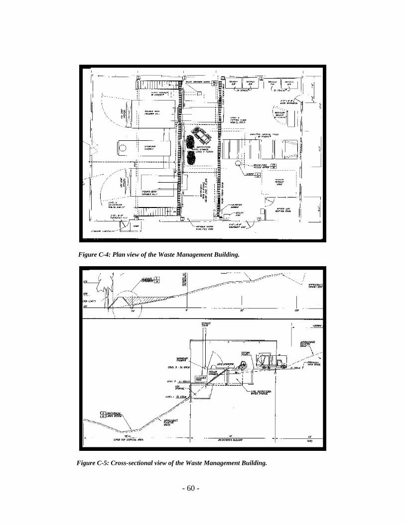
- 60 -
Figure C-4: Plan view of the Waste Management Building.
Figure C-5: Cross-sectional view of the Waste Management Building.
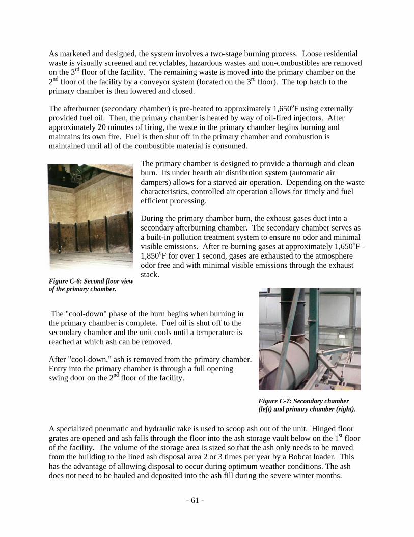
- 61 -
As marketed and designed, the system involves a two-stage burning process. Loose residential waste is visually screened and recyclables, hazardous wastes and non-combustibles are removed on the 3rd floor of the facility. The remaining waste is moved into the primary chamber on the 2nd floor of the facility by a conveyor system (located on the 3rd floor). The top hatch to the primary chamber is then lowered and closed.
The afterburner (secondary chamber) is pre-heated to approximately 1,650oF using externally provided fuel oil. Then, the primary chamber is heated by way of oil-fired injectors. After approximately 20 minutes of firing, the waste in the primary chamber begins burning and maintains its own fire. Fuel is then shut off in the primary chamber and combustion is maintained until all of the combustible material is consumed.
The primary chamber is designed to provide a thorough and clean burn. Its under hearth air distribution system (automatic air dampers) allows for a starved air operation. Depending on the waste characteristics, controlled air operation allows for timely and fuel efficient processing.
During the primary chamber burn, the exhaust gases duct into a secondary afterburning chamber. The secondary chamber serves as a built-in pollution treatment system to ensure no odor and minimal visible emissions. After re-burning gases at approximately 1,650oF - 1,850oF for over 1 second, gases are exhausted to the atmosphere odor free and with minimal visible emissions through the exhaust stack.
The "cool-down" phase of the burn begins when burning in the primary chamber is complete. Fuel oil is shut off to the secondary chamber and the unit cools until a temperature is reached at which ash can be removed.
After "cool-down," ash is removed from the primary chamber. Entry into the primary chamber is through a full opening swing door on the 2nd floor of the facility.
A specialized pneumatic and hydraulic rake is used to scoop ash out of the unit. Hinged floor grates are opened and ash falls through the floor into the ash storage vault below on the 1st floor of the facility. The volume of the storage area is sized so that the ash only needs to be moved from the building to the lined ash disposal area 2 or 3 times per year by a Bobcat loader. This has the advantage of allowing disposal to occur during optimum weather conditions. The ash does not need to be hauled and deposited into the ash fill during the severe winter months.
Figure C-7: Secondary chamber (left) and primary chamber (right).
Figure C-6: Second floor view of the primary chamber.

- 62 -
One complete combustion cycle burning 8 tons of garbage takes approximately 24 hours. At the end of 24 hours, the ash is cool enough to remove from the unit. The original volume of waste is reduced by over 90% and the remaining products are sterilized ash, metals and glass suitable for recycling. Burning with this unit should comply with state and federal air quality, water quality and solid waste standards. Regular ash and leachate monitoring have shown compliance with standards.
An automated, operator control system is installed for minimal labor and efficient use of fuel. Trouble-shooting and diagnostics are done via a modem and telephone line to reduce the need for on-site technicians.
The operator control system is supplied with a computer workstation that is located near the equipment and at the public works building in town. This workstation also automatically records operating parameters and makes them available for printing and record keeping.
The ash disposal facility is lined with 60 mil HDPE installed over a woven geotextile fabric cushion on a 4-inch layer of sand.
Figure C-11: Automated operator control system.
Figure C-8: Pneumatic Rake.
Figure C-9: Ash falls through grate.
Figure C-10: Ash in storage vault.
Figure C-12: Lined ashfill.

- 63 -
The initial disposal area was sized to accommodate approximately 11 years of ash. Thus far, the facility has operated for approximately 2.5 years and the amount of ash delivered to the site indicates that the original 11-year life span will be exceeded.
The lined area drains to a 65,000-gallon leachate collection pond at its lower end. The ash contact water (leachate) at the collection pond can be handled as follows:
• recycled back onto the ash disposal area;
• pumped to the ash storage room to moisten the stockpiled ash;
• pumped for use in the water injection system for the burning process in the primary chamber;
• pumped to a tank truck for transport to Skagway's waste water treatment plan; or
• released to the environment given acceptable water quality results. Contact water from this facility has shown compliance with water quality
standards.
New Technology: Issues and Problems
The Skagway incineration project was the first large thermal oxidation system of its kind installed in Alaska by the manufacturer. When dealing with new technology, there were bound to be problems which both the manufacturer and the City of Skagway were committed to solving. In some cases, solving one problem merely create another. The experience Skagway gained in developing this facility may be useful to other communities that are planning similar systems.
Burn Time
In the summer during peak demand (tourist season), it is important that a burn be completed and the unit ready to accept a new load of waste within 24 hours. The initial problem that needed to be addressed was the increased time for the "cool-down" phase of the burn that caused the total combustion cycle to exceed 24 hours.
The primary chamber in the unit was designed to burn at 1,000o F. As built, the temperature in the primary chamber was higher than 1,000o F which caused the longer "cool down" time. It was not exactly clear why this was so. However, the large size (thermal mass) of the primary chamber may have been a cause (the 25-cubic-yard primary chamber is sized to burn 8 tons of garbage). Another factor may have been the BTU value of the waste. In the summer, the waste stream tends to have less moisture than normal municipal garbage because of the amount of packaging material generated by tourist shops.
Figure C-13: Ashfill leachate at the ash fill.

- 64 -
Larger blowers were installed in order to shorten the burn time in the primary chamber and allow more time for cool down. However, this caused a hotter burn that did not substantially affect the total burn time but did cause warping of the refractories.
A fine mist of water injected into the primary chamber solved the problem. This kept the temperature in the primary chamber consistently at 1,000 oF. Water injection also accelerated the cool down phase of the burn. The water for the injection system came from an on-site reservoir (cistern) for a fire suppression system. The city plans to recycle the leach water from the ash fill back into the injection system. This will also decrease the discharge of ash contact water from the facility.
Fuel Usage
Fuel costs are the most expensive part of the operation at $53,000/year (Skagway FY 2002). Anything that can help to decrease fuel costs will help decrease the overall operational cost and the cost to the consumer. However, the fuel issues are driven by Skagway's commitment to no visible emissions.
According to the manufacturer, once the burn cycle is done and the cool down phase commences, the fuel should be shut off in the secondary chamber. However, it was found that shutting off the fuel in the secondary chamber at the cool-down phase created a visible emission (although this was within legal air quality opacity limits). Because the community was committed to no visible emissions, fuel is burned in the secondary chamber throughout the cool-down phase. This adds to both fuel usage and cost. Skagway estimates that shutting off the fuel during the cool-down phase, as the manufacturer recommends, would reduce fuel consumption by about half.
Originally, fuel consumption was about 330 gallons per burn. Subtle modifications to the injection system helped to reduce fuel consumption. Today, an 8-ton burn at this facility uses 280 gallons of fuel.
Mining and Burning Waste From the Old Raw Garbage Site
The city originally tried to burn waste from the old municipal solid waste site. However, this stopped after the city determined the waste from the old landfill was too expensive to burn. The waste from the old site had decreased BTU value due to bio-degradation of the wastes in the landfill. Also, much of the material from the old landfill was unburnable soil cover material. Separation of the gravel/rock cover material from the burnable garbage would require specialized machinery that was expensive.
Refractory Liners
Refractory liners created another problem. The refractory liners installed with the unit were intended to last the life of the unit. The original refractory was manufactured to be durable and rigid. However, the refractory was sensitive to heat deformation and warped at the higher unit

- 65 -
temperatures. Therefore, the refractory liner had to be replaced with a different type of liner than was initially installed.
The new liner is composed of replaceable modules that are roughly a foot square in size. Although more resistant to heat deformation, the new refractory modules are somewhat fragile and may need to be replaced as they will shrink and detach over time. This is particularly true with the ceiling of the unit that receives more heat. The modules will last a long time, if not damaged by the heavy items that fall in to the primary chamber during the loading process. The city is getting the training and technology from the manufacturer to change these refractory liners in-house. However, Skagway must budget for the replacement of the modules and this is an on-going maintenance issue. Replacement of the refractory modules hasn't significantly impacted the rate base to customers.
Building Dust
Dust blowing around in the building created another problem. The ash from the unit is very fine. As ash is scooped out of the primary chamber it falls through the floor into the ash storage vault below. The ash has a tendency to blow back up through the grate in the floor and circulate around in the building. The city has planned to install high volume fans in the ash vault to create a negative pressure. The fans will have filters on them to prevent ash from leaving the building. The fans are planned for installation in 2002.
Funding Sources, Cost Comparisons and Costs of Operation
The total cost for this project was $2,400,000. The community acquired a $2,000,000 low interest loan through ADEC from EPA Clean Water Act funds. Local sales tax revenues also funded the project. The only reason Skagway can maintain a low rate to customers is because they fund the debt service through a 4% sales tax and the major source of waste to the facility is through the tourism industry. Not many communities have this flexibility.
Low Interest Loans
A huge benefit to Skagway was the fact that the interest on their loan was lower than the interest earned on the city’s reserves. Since they are able to pay off the loan without reducing their reserves, the city is able to subsidize the solid waste utility with a sales tax that is mostly paid by seasonal visitors. This is appropriate since it is the huge influx of seasonal visitors that necessitates a facility that far exceeds the needs of the resident population.
Project Comparisons for Other Rural Alaskan Communities
The cost for the Skagway facility is higher than for other Alaskan communities of similar population for the following reasons.
1. Skagway's location is a unique, mountainside site, which added greatly to the cost. About 70% of the $2.4 million total cost of the facility was spent on site development of the ash fill and enclosure.

- 66 -
2. Skagway elected to build a lined ash fill. This was not a requirement, but reflected the community's desire to go the extra step to ensure environmental protection. This added about $100,000 to the expense of the facility. Other communities may not wish to build a lined facility for their ash depending upon the need to protect water quality.
A smaller incinerator with reduced operating expense, a less complicated site, lack of need for a lined ash fill, and a reduced waste stream could significantly reduce the cost of the facility and the cost to the garbage ratepayer. City management suggests a small community without the influx of seasonal visitors, building on flat land, could develop a site for much less, perhaps less than $500,000. (This estimate is made without full knowledge of the logistics involved in getting the needed materials and equipment to remote areas).
General Comments
Skagway did not develop an incinerator because it was the least expensive alternative. The community decided to develop this facility to protect self-determination in the long-term management and disposal of solid waste. They are fortunate to have financed the project through means other than the garbage rate base, which does keep the cost to customers down. According to city management "Others might not have this advantage, but in areas where land is scarce, or where wind-blown and vector-carried debris make landfilling unsafe, unsanitary and unsightly, incineration is a very viable option. We now have a decades-long solution to our solid waste disposal issue, which we would not have enjoyed with continued landfilling or transshipment."
Service Charges and Expenses
The monthly charge for a 2-can-per-week pickup in Skagway is $20.00 for residential service.
Below is the proposed Skagway solid waste budget for FY-2002. Please note these expenses include the collection costs. Also, most of the expenses listed below would be the same for a raw garbage landfill or transshipment. Furthermore, these figures do not detail the true operating costs specific to the incinerator. It is difficult to separate those costs because of cost overlaps. For instance, the operator for the incinerator is also the garbage collector and hauler, fuel for the garbage truck is included in the fuel costs, and maintenance for the garbage truck is included in the maintenance cost.
Budgetary expenses for FY-2002 - (includes collection costs)
1. Administrative $ 9,000 2. Capital Outlay $ 6,000 3. Hazardous Waste $10,000 4. Contractual $ 6,000 5. Employee Payroll Ex $35,500 6. Insurance $ 6,000 7. Repairs / Maintenance $12,000 8. Salaries $78,000 9. Training $ 2,000 10. Utilities - Incineration (fuel) $53,000 11. Recycling $ 9,000 TOTAL $280,500

- 67 -
Appendix D – Small Direct Waste Combustor Database
This database is a compilation of information provided to University of Alaska Anchorage (UAA), Alaska Energy Authority (AEA) and Alaska Department of Environmental Conservation (ADEC) by incinerator vendors between June 2000 and June 2003. It is intended to be a general guide to incinerators available for small-scale waste treatment.
Although the authors have tried to represent vendor claims as accurately as possible, it should be noted that performance of incinerators varies widely depending on the type of system and quality of the waste burned, particularly moisture content. Cycle time and requirement for supplementary fuel are quite sensitive to the quality of waste treated. The authors and their agencies cannot guarantee the accuracy of the information presented here. Communities and individuals considering incineration should contact vendors for more specific information, or other communities that have experience with the particular system.
The database contains 87 systems constructed or sold by 34 private companies or public organizations. Systems were included if they appeared suitable for communities generating up to 10 tons of waste per day. It should be noted that some vendors sell more models in this size range than are listed here, some models may no longer be available, and specifications may have changed. Systems were identified based on contacts with incinerator operators, public agencies, and vendors. AEA and ADEC will update the database as time and resources are available.
Following are descriptions of some of the columns in the database. Blank fields indicate that no information was either available or collected.
Cost. System cost quoted for 2000-2001. Cost was requested for a “turn-key” system not including other components that may be necessary, such as a transfer station or pad (see Other Systems Needed). Costs are given FOB Anchorage unless otherwise stated.
Throughput. This is the average amount of waste in pounds that can be processed by the incinerator per hour. For a batch system, throughput is the weight of waste in a batch divided by the total cycle time, including a cool-down period. As noted above, throughput is heavily influenced by the quality of waste.
Dimensions. Dimensions include the incinerator only, not the stack or other associated equipment unless noted.
Supplementary Fuel. Most systems require fuel oil, natural gas, or propane to ensure complete combustion. However, suppliers of burn boxes and several other systems claim to be able to use only refuse-derived fuel “RDF”, loosely defined as municipal solid waste with non-combustibles removed, comprised mostly of paper and cardboard.
Supplementary Fuel Usage (gallons per batch or ton). As noted above, supplementary fuel usage is heavily influenced by quality of waste burned. The numbers given should be regarded as very rough approximations.

- 68 -
Source Test Available. This indicates whether air emission tests have been completed for an incinerator and are available from the vendor upon request.
Can Burn Used Oil / Sewage Sludge / Medical Waste. If yes, the vendor indicates that the incinerator is capable of burning these items. ADEC should be contacted for permitting requirements.

Appendix D, Table 1. Vendor Database (May 2004)
Company Contact Phone Fax Street Address CityState /
Province Postal Code Country Web Address Email Address
Advanced Combustion Systems, Inc. 'Mike Milnes (360-676-6005) (360-647-9439) 1998 Alpine Way Bellingham WA 98226 USA www.acs-acs.com [email protected]
Air Burners Bert Blackadar (907-230-2113) (561-220-7302) 4390 Cargo Way Palm City FL 34990 USA www.airburners.com [email protected]
Alakanuk City Council Raymond Oney (907-238-3313) (907-238-3620) P.O. Box 167 Alakanuk AK 99554 USA N/A N/A
Alaska Native Tribal Health Consortium 'Dan Schubert (907-729-3600) 907-729-1901 4141 Ambassador Drive Anchorage AK 99508 USA www.anthc.org N/A
Allied Furnaces Allied House (+91) 22 - 528 4028(+91) 22 - 528 3805 1st Road, opp. Municipal Office Chembur Mumbai
400 071 Indiawww.alliedfurnaces.com [email protected]
Ambler Traditional Council 'Virginia Commack (907-445-2238) (907-445-2122) P.O. Box 9 Ambler AK 99786 USA N/A
American 3CI318 - 869 04 40 318 - 869 40 02 911 Pierremont, #312 Shreveport
LA 71107 USA http://www.am3ci.com/ http://www.am3ci.com/
Asa'carsamiut Tribe-Mtn. Village 'Andrea Bongen (907-591-2834) 907-591-2811 P.O. Box 32249 Mountain Village AK 99632 USA [email protected]
Caddet: Advanced Thermal Conversion Technologies for Energy from Solid Waste Marilyn Brown, Julia Kelley 865-5768152 / 5741013 865-2410112 / 5749329
P.O. Box 2008
Oakridge TN 37831-6186 USA http://www.caddet-re.org/assets/EFW.pdf
Chenega Bay IRA Council 'Larry Evanoff (907-573-5132) 907-573-5120 P.O. Box 8079 Chenega Bay AK 99574 USA
City of Aleknaqik 'Mike Shuler (907-842-5953) (907-842-2107) P.O. Box 333 Aleknagik AK 99555 USA [email protected].
City of Hughes 'Thelma Nicholia (907-889-2206) 907-889-2252 P.O. Box 45010 Hughes AK 99745 USA N/A
City of Marshall 'Raymond D. Alstrom (907-679-6215) 907-679-6220 P.O. Box 9 Marshall AK 99585 USA N/A
Crawford Equipment 'Luis Llorens (407-851-0993 ext 259) 407-851-2406P.O. Box 593243
Orlando FL32859-3243
Crochet Equipment 'Ronnie Crochet (225-927-2019) (504-926-4915) P.O. Box 15338 Baton Rouge LA 70895 USA www.recycle.net N/A
Dot Lake Village Council 'William Miller (907-883-4227) (907-883-4223) P.O. Box 2275 Dot Lake AK 99737 USA N/A
Eco-Waste Solutions (905)634-7022 (905) 634-0831 5196 Harvester Road, Unit 6 Burlington Ontario L7L 6E10 Canada http://www.eco-waste.com/
EEC Engineering 'Tomek Rondio CEO (415-386-6424)
Elastec Inc. 618-382-2526 618-382-3611 122 Council St. Carmi IL 62821 USA elastec.com http://www.elastec.com/
Elim IRA Council 'Luther Nagaruk (907-890-3737) (907-890-3811) P.O. Box 39009 Elim AK 99739 USA N/A
EnerWaste International Corporation (360) 738-1254 (360) 738-1376 PO Box 1194 Bellingham WA 98227 USA http://www.enerwaste.com/
Entech 817.379.0100 817.379.0300 1077 Chisolm Trail Keller TX 76248 USA entechsolar.com
Garness Industrial Inc. (907-562-2933) N/A 6317 Nielson Way Anchorage AK 99518 USA [email protected]
GMG Systems (516) 877-7410 (516) 877-7419 450 Jericho Tnpk. Suite 203 Mineola NY 11501 USA gmgsystems.com/ [email protected]
Goodnews Bay, Traditional Village 'Alice Julius (907-967-8929) (907- 967-8124) P.O. Box 139 Goodnews Bay AK 99589 USA N/A N/A
Incinerator International Inc. (713) 463-5555 (713) 463-5557 1003 Wirt Road Suite 208 Houston TX 77055 USA www.incinerators.com [email protected]
Incinerator Specialists 330-723-6339 or 1-888-883-BURN 330-723-5841 734 N. Progress Dr Medina OH 44256 USA incineratorspecialists.com/ http://www.incineratorspecialists.com/
Infratech Corporation 780-778-4226 or 1-888-377-5432 780-778-4220 3415 35th Avenue Whitecourt AL T7S 1P7 USA www.infratechgroup.com [email protected]
Iron Age Reclamation 'Duke Marshall (907-883-5311) USA www.educable.org/a011.html
Kobuk Traditional Council 'Eileen R. Jackson (907-948-2203) 907-948-2123 P.O. Box 39009 Kobuk AK 99751 USA [email protected] N/A
Mcpherson Systems Inc. 'Tony McPherson (912-386-8054) (229-387-0132) Hwy 82 W. 100 Springhill Church Road Tifton GA 31794 USA N/A
Nanwalek IRA Council 'Tom Evans (907-281-2221) (907-281-2252) P.O. Box 8028 Nanwalek AK 99603-6628 USA N/A [email protected]
National Incinerator Inc. 'Otto Baker (800-544-0661) (903-872-6060) P.O. Box 1651 Corsicana TX 75151 USA www.national-incinerator.com. [email protected]
Native Village of Noatak 'Wilfred R. Ashby (907-485-2236) (907-485-2137) P.O. Box 89 Noatak AK 99761 USA [email protected]
NCE Corporation 716-671-0370 716-671-9337 899 Ridge Road Webster NY 14580 USA ncedcc.com/service.html [email protected]
OSSYS, LLC 'Gene Andrews (907-780-4636) (907) 780-4907 P.O. Box 210189 Auke Bay AK 99821 USA N/A [email protected]
Pedro Bay Village Council 'John M. Baalke (907-850-2225) (907-850-2221) P.O. Box 47020 Pedro Bay AK 99647 USA N/A [email protected]
Simmons Manufacturing 770-957-3976 770-957-3979 1608 Conyers Rd. McDonough GA 30253 USA www.simmonsmfg.com [email protected]
Stelter and Brinck(+1) 513 - 367 93 00 (+1) 513 - 367 15 24 201 Sales Avenue Harrison
OH45030
USA www.stelterbrinck.com [email protected]
Tanacross Village Council 'Glenn Dailey (907-883-5024) (907-883-4497) P.O. Box 77130 Tanacross AK 99776 USA N/A [email protected]
Therm Tec Inc. 'Jim Seaman (907-562-2608) (503-625-6161) P.O. Box 1105 Tualatin OR 97062 USA www.thermtec.com [email protected]
Thermogenics 7100-F Second Street NW Albuquerque NM 87107 USA http://www.thermogenics.com/default.html
Page 1
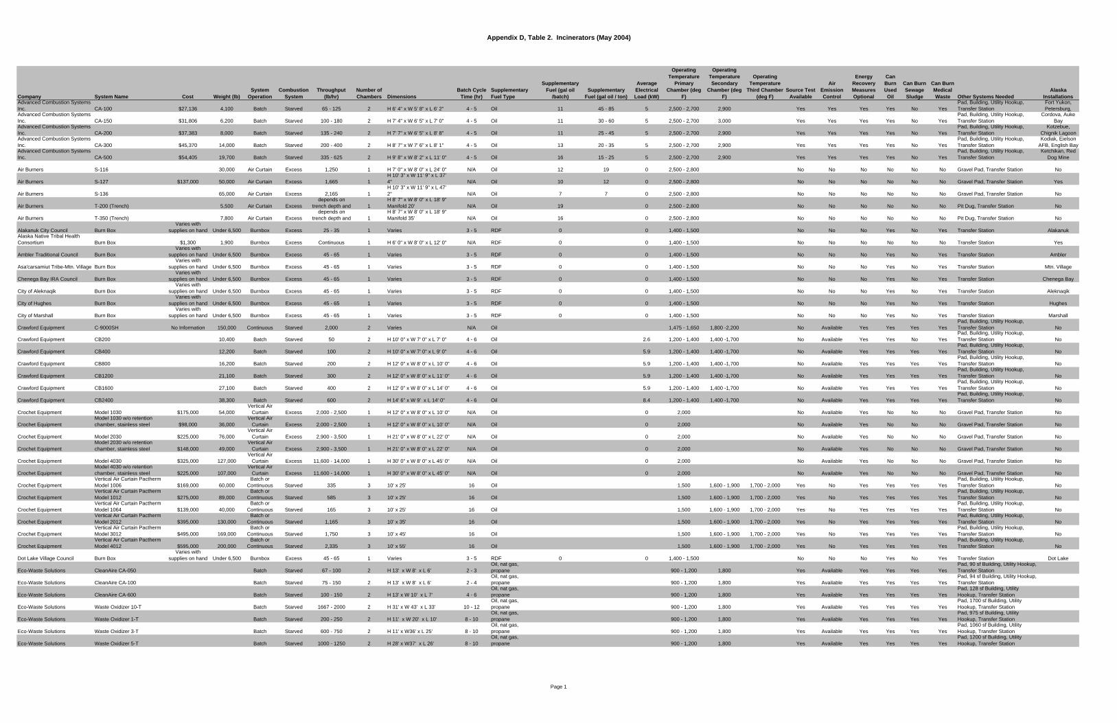
Appendix D, Table 2. Incinerators (May 2004)
Company System Name Cost Weight (lb)System
OperationCombustion
SystemThroughput
(lb/hr)Number of Chambers Dimensions
Batch Cycle Time (hr)
Supplementary Fuel Type
Supplementary Fuel (gal oil
/batch)Supplementary
Fuel (gal oil / ton)
Average Electrical Load (kW)
Operating Temperature
Primary Chamber (deg
F)
Operating Temperature Secondary
Chamber (deg F)
Operating Temperature
Third Chamber (deg F)
Source Test Available
Air Emission Control
Energy Recovery Measures Optional
Can Burn Used Oil
Can Burn Sewage Sludge
Can Burn Medical Waste Other Systems Needed
Alaska Installations
Advanced Combustion Systems Inc. CA-100 $27,136 4,100 Batch Starved 65 - 125 2 H 6' 4" x W 5' 8" x L 6' 2" 4 - 5 Oil 11 45 - 85 5 2,500 - 2,700 2,900 Yes Yes Yes Yes No Yes
Pad, Building, Utility Hookup, Transfer Station
Fort Yukon, Petersburg,
Advanced Combustion Systems Inc. CA-150 $31,806 6,200 Batch Starved 100 - 180 2 H 7' 4" x W 6' 5" x L 7' 0" 4 - 5 Oil 11 30 - 60 5 2,500 - 2,700 3,000 Yes Yes Yes Yes No Yes
Pad, Building, Utility Hookup, Transfer Station
Cordova, Auke Bay
Advanced Combustion Systems Inc. CA-200 $37,383 8,000 Batch Starved 135 - 240 2 H 7' 7" x W 6' 5" x L 8' 8" 4 - 5 Oil 11 25 - 45 5 2,500 - 2,700 2,900 Yes Yes Yes Yes No Yes
Pad, Building, Utility Hookup, Transfer Station
Kotzebue, Chignik Lagoon
Advanced Combustion Systems Inc. CA-300 $45,370 14,000 Batch Starved 200 - 400 2 H 8' 7" x W 7' 6" x L 8' 1" 4 - 5 Oil 13 20 - 35 5 2,500 - 2,700 2,900 Yes Yes Yes Yes No Yes
Pad, Building, Utility Hookup, Transfer Station
Kodiak, Eielson AFB, English Bay
Advanced Combustion Systems Inc. CA-500 $54,405 19,700 Batch Starved 335 - 625 2 H 9' 8" x W 8' 2" x L 11' 0" 4 - 5 Oil 16 15 - 25 5 2,500 - 2,700 2,900 Yes Yes Yes Yes No Yes
Pad, Building, Utility Hookup, Transfer Station
Ketchikan, Red Dog Mine
Air Burners S-116 30,000 Air Curtain Excess 1,250 1 H 7' 0" x W 8' 0" x L 24' 0" N/A Oil 12 19 0 2,500 - 2,800 No No No No No No Gravel Pad, Transfer Station No
Air Burners S-127 $137,000 50,000 Air Curtain Excess 1,665 1H 10' 3" x W 11' 9" x L 37' 4" N/A Oil 10 12 0 2,500 - 2,800 No No No No No No Gravel Pad, Transfer Station Yes
Air Burners S-136 65,000 Air Curtain Excess 2,165 1H 10' 3" x W 11' 9" x L 47' 2" N/A Oil 7 7 0 2,500 - 2,800 No No No No No No Gravel Pad, Transfer Station No
Air Burners T-200 (Trench) 5,500 Air Curtain Excessdepends on
trench depth and 1H 8' 7" x W 8' 0" x L 18' 9" Manifold 20' N/A Oil 19 0 2,500 - 2,800 No No No No No No Pit Dug, Transfer Station No
Air Burners T-350 (Trench) 7,800 Air Curtain Excessdepends on
trench depth and 1H 8' 7" x W 8' 0" x L 18' 9" Manifold 35' N/A Oil 16 0 2,500 - 2,800 No No No No No No Pit Dug, Transfer Station No
Alakanuk City Council Burn BoxVaries with
supplies on hand Under 6,500 Burnbox Excess 25 - 35 1 Varies 3 - 5 RDF 0 0 1,400 - 1,500 No No No Yes No Yes Transfer Station AlakanukAlaska Native Tribal Health Consortium Burn Box $1,300 1,900 Burnbox Excess Continuous 1 H 6' 0" x W 8' 0" x L 12' 0" N/A RDF 0 0 1,400 - 1,500 No No No No No No Transfer Station Yes
Ambler Traditional Council Burn BoxVaries with
supplies on hand Under 6,500 Burnbox Excess 45 - 65 1 Varies 3 - 5 RDF 0 0 1,400 - 1,500 No No No Yes No Yes Transfer Station Ambler
Asa'carsamiut Tribe-Mtn. Village Burn BoxVaries with
supplies on hand Under 6,500 Burnbox Excess 45 - 65 1 Varies 3 - 5 RDF 0 0 1,400 - 1,500 No No No Yes No Yes Transfer Station Mtn. Village
Chenega Bay IRA Council Burn BoxVaries with
supplies on hand Under 6,500 Burnbox Excess 45 - 65 1 Varies 3 - 5 RDF 0 0 1,400 - 1,500 No No No Yes No Yes Transfer Station Chenega Bay
City of Aleknaqik Burn BoxVaries with
supplies on hand Under 6,500 Burnbox Excess 45 - 65 1 Varies 3 - 5 RDF 0 0 1,400 - 1,500 No No No Yes No Yes Transfer Station Aleknaqik
City of Hughes Burn BoxVaries with
supplies on hand Under 6,500 Burnbox Excess 45 - 65 1 Varies 3 - 5 RDF 0 0 1,400 - 1,500 No No No Yes No Yes Transfer Station Hughes
City of Marshall Burn BoxVaries with
supplies on hand Under 6,500 Burnbox Excess 45 - 65 1 Varies 3 - 5 RDF 0 0 1,400 - 1,500 No No No Yes No Yes Transfer Station Marshall
Crawford Equipment C-9000SH No Information 150,000 Continuous Starved 2,000 2 Varies N/A Oil 1,475 - 1,650 1,800 -2,200 No Available Yes Yes Yes YesPad, Building, Utility Hookup, Transfer Station No
Crawford Equipment CB200 10,400 Batch Starved 50 2 H 10' 0" x W 7' 0" x L 7' 0" 4 - 6 Oil 2.6 1,200 - 1,400 1,400 -1,700 No Available Yes Yes No YesPad, Building, Utility Hookup, Transfer Station No
Crawford Equipment CB400 12,200 Batch Starved 100 2 H 10' 0" x W 7' 0" x L 9' 0" 4 - 6 Oil 5.9 1,200 - 1,400 1,400 -1,700 No Available Yes Yes Yes YesPad, Building, Utility Hookup, Transfer Station No
Crawford Equipment CB800 16,200 Batch Starved 200 2 H 12' 0" x W 8' 0" x L 10' 0" 4 - 6 Oil 5.9 1,200 - 1,400 1,400 -1,700 No Available Yes Yes Yes YesPad, Building, Utility Hookup, Transfer Station No
Crawford Equipment CB1200 21,100 Batch Starved 300 2 H 12' 0" x W 8' 0" x L 11' 0" 4 - 6 Oil 5.9 1,200 - 1,400 1,400 -1,700 No Available Yes Yes Yes YesPad, Building, Utility Hookup, Transfer Station No
Crawford Equipment CB1600 27,100 Batch Starved 400 2 H 12' 0" x W 8' 0" x L 14' 0" 4 - 6 Oil 5.9 1,200 - 1,400 1,400 -1,700 No Available Yes Yes Yes YesPad, Building, Utility Hookup, Transfer Station No
Crawford Equipment CB2400 38,300 Batch Starved 600 2 H 14' 6" x W 9' x L 14' 0" 4 - 6 Oil 8.4 1,200 - 1,400 1,400 -1,700 No Available Yes Yes Yes YesPad, Building, Utility Hookup, Transfer Station No
Crochet Equipment Model 1030 $175,000 54,000Vertical Air
Curtain Excess 2,000 - 2,500 1 H 12' 0" x W 8' 0" x L 10' 0" N/A Oil 0 2,000 No Available Yes No No No Gravel Pad, Transfer Station No
Crochet EquipmentModel 1030 w/o retention chamber, stainless steel $98,000 36,000
Vertical Air Curtain Excess 2,000 - 2,500 1 H 12' 0" x W 8' 0" x L 10' 0" N/A Oil 0 2,000 No Available Yes No No No Gravel Pad, Transfer Station No
Crochet Equipment Model 2030 $225,000 76,000Vertical Air
Curtain Excess 2,900 - 3,500 1 H 21' 0" x W 8' 0" x L 22' 0" N/A Oil 0 2,000 No Available Yes No No No Gravel Pad, Transfer Station No
Crochet EquipmentModel 2030 w/o retention chamber, stainless steel $148,000 49,000
Vertical Air Curtain Excess 2,900 - 3,500 1 H 21' 0" x W 8' 0" x L 22' 0" N/A Oil 0 2,000 No Available Yes No No No Gravel Pad, Transfer Station No
Crochet Equipment Model 4030 $325,000 127,000Vertical Air
Curtain Excess 11,600 - 14,000 1 H 30' 0" x W 8' 0" x L 45' 0" N/A Oil 0 2,000 No Available Yes No No No Gravel Pad, Transfer Station No
Crochet EquipmentModel 4030 w/o retention chamber, stainless steel $225,000 107,000
Vertical Air Curtain Excess 11,600 - 14,000 1 H 30' 0" x W 8' 0" x L 45' 0" N/A Oil 0 2,000 No Available Yes No No No Gravel Pad, Transfer Station No
Crochet EquipmentVertical Air Curtain Pactherm Model 1006 $169,000 60,000
Batch or Continuous Starved 335 3 10' x 25' 16 Oil 1,500 1,600 - 1,900 1,700 - 2,000 Yes No Yes Yes Yes Yes
Pad, Building, Utility Hookup, Transfer Station No
Crochet EquipmentVertical Air Curtain Pactherm Model 1012 $275,000 89,000
Batch or Continuous Starved 585 3 10' x 25' 16 Oil 1,500 1,600 - 1,900 1,700 - 2,000 Yes No Yes Yes Yes Yes
Pad, Building, Utility Hookup, Transfer Station No
Crochet EquipmentVertical Air Curtain Pactherm Model 1064 $139,000 40,000
Batch or Continuous Starved 165 3 10' x 25' 16 Oil 1,500 1,600 - 1,900 1,700 - 2,000 Yes No Yes Yes Yes Yes
Pad, Building, Utility Hookup, Transfer Station No
Crochet EquipmentVertical Air Curtain Pactherm Model 2012 $395,000 130,000
Batch or Continuous Starved 1,165 3 10' x 35' 16 Oil 1,500 1,600 - 1,900 1,700 - 2,000 Yes No Yes Yes Yes Yes
Pad, Building, Utility Hookup, Transfer Station No
Crochet EquipmentVertical Air Curtain Pactherm Model 3012 $495,000 169,000
Batch or Continuous Starved 1,750 3 10' x 45' 16 Oil 1,500 1,600 - 1,900 1,700 - 2,000 Yes No Yes Yes Yes Yes
Pad, Building, Utility Hookup, Transfer Station No
Crochet EquipmentVertical Air Curtain Pactherm Model 4012 $595,000 200,000
Batch or Continuous Starved 2,335 3 10' x 55' 16 Oil 1,500 1,600 - 1,900 1,700 - 2,000 Yes No Yes Yes Yes Yes
Pad, Building, Utility Hookup, Transfer Station No
Dot Lake Village Council Burn BoxVaries with
supplies on hand Under 6,500 Burnbox Excess 45 - 65 1 Varies 3 - 5 RDF 0 0 1,400 - 1,500 No No No Yes No Yes Transfer Station Dot Lake
Eco-Waste Solutions CleanAire CA-050 Batch Starved 67 - 100 2 H 13' x W 8' x L 6' 2 - 3Oil, nat gas, propane 900 - 1,200 1,800 Yes Available Yes Yes Yes Yes
Pad, 90 sf Building, Utility Hookup, Transfer Station
Eco-Waste Solutions CleanAire CA-100 Batch Starved 75 - 150 2 H 13' x W 8' x L 6' 2 - 4Oil, nat gas, propane 900 - 1,200 1,800 Yes Available Yes Yes Yes Yes
Pad, 94 sf Building, Utility Hookup, Transfer Station
Eco-Waste Solutions CleanAire CA-600 Batch Starved 100 - 150 2 H 13' x W 10' x L 7' 4 - 6Oil, nat gas, propane 900 - 1,200 1,800 Yes Available Yes Yes Yes Yes
Pad, 128 sf Building, Utility Hookup, Transfer Station
Eco-Waste Solutions Waste Oxidizer 10-T Batch Starved 1667 - 2000 2 H 31' x W 43' x L 33' 10 - 12Oil, nat gas, propane 900 - 1,200 1,800 Yes Available Yes Yes Yes Yes
Pad, 1700 sf Building, Utility Hookup, Transfer Station
Eco-Waste Solutions Waste Oxidizer 1-T Batch Starved 200 - 250 2 H 11' x W 20' x L 10' 8 - 10Oil, nat gas, propane 900 - 1,200 1,800 Yes Available Yes Yes Yes Yes
Pad, 975 sf Building, Utility Hookup, Transfer Station
Eco-Waste Solutions Waste Oxidizer 3-T Batch Starved 600 - 750 2 H 11' x W36' x L 25' 8 - 10Oil, nat gas, propane 900 - 1,200 1,800 Yes Available Yes Yes Yes Yes
Pad, 1060 sf Building, Utility Hookup, Transfer Station
Eco-Waste Solutions Waste Oxidizer 5-T Batch Starved 1000 - 1250 2 H 28' x W37' x L 26' 8 - 10Oil, nat gas, propane 900 - 1,200 1,800 Yes Available Yes Yes Yes Yes
Pad, 1200 sf Building, Utility Hookup, Transfer Station
Page 1

Appendix D, Table 2. Incinerators (May 2004)
Company System Name Cost Weight (lb)System
OperationCombustion
SystemThroughput
(lb/hr)Number of Chambers Dimensions
Batch Cycle Time (hr)
Supplementary Fuel Type
Supplementary Fuel (gal oil
/batch)Supplementary
Fuel (gal oil / ton)
Average Electrical Load (kW)
Operating Temperature
Primary Chamber (deg
F)
Operating Temperature Secondary
Chamber (deg F)
Operating Temperature
Third Chamber (deg F)
Source Test Available
Air Emission Control
Energy Recovery Measures Optional
Can Burn Used Oil
Can Burn Sewage Sludge
Can Burn Medical Waste Other Systems Needed
Alaska Installations
EEC Engineering Gasifier $1,186,000 Under
100,000 Continuous Gasification 2000 1 N/A None required 0Produces 800
kW with 1,800 Yes No Yes Yes Yes NoPad, 2000 sf Building ,Utility Hookup, Transfer Station No
Elim IRA Council Burn BoxVaries with
supplies on hand Under 6,500 Burnbox Excess 45 - 65 1 Varies 3 - 5 RDF 0 0 1,400 - 1,500 No No No Yes No Yes Transfer Station ElimEnerWaste International Corporation Batch Oxidation System Batch 70,000 Batch Starved 800 2
H 8'3" x W 10' x L 12', Stack L 20' N/A
Oil, nat gas, propane 27 - 35 10 2.3 800 1750 No Yes Yes
Pad, Building ,Utility Hookup, Transfer Station Egegik
Entech Thermal Oxidation SystemNo longer in production Batch Starved 2 N/A Natural gas Yes No Yes Yes
Pad, Building ,Utility Hookup, Transfer Station
Anchorage, Prudhoe Bay
Garness Industrial Inc. 16,500 Batch Excess 30 - 35 2 H 10' x W 7' x L 9' 4 to 6 Oil 1,500 1,750 No No No Yes No YesPad, Building ,Utility Hookup, Transfer Station Cook Inlet
Garness Industrial Inc. 17,950 Batch Excess 25 - 30 2 H 9' x W 7' x L 8' 5" 4 to 6 Oil 1,500 1,750 No No No Yes No YesPad, Building ,Utility Hookup, Transfer Station Prudhoe Bay
Goodnews Bay, Traditional Village Burn Box
Varies with supplies on hand Under 6,500 Burnbox Excess 45 - 65 1 Varies 3 - 5 RDF 0 0 1,400 - 1,500 No No No Yes No Yes Transfer Station Goodnews Bay
Incinerator International Inc. 2500-CA $160,000 75000 Continuous Starved 2500 2 N/AOil, nat gas, propane 15 - 20 13 1500-1800 1800-2000 No No Yes Yes Yes
Pad, Building ,Utility Hookup, Transfer Station No
Infratech Corporation 10M$300,000 FOB
factoryContinuous (ram feed) Starved 1,500 2
H 12' x W 7' x L 14.6', not incl ram feeder N/A
Oil, nat gas, propane 27 13.5 max 1,800 1,800 No Available Yes Yes Yes Yes
Pad, Building ,Utility Hookup, Transfer Station
Canadian installations
Iron Age Reclamation Burn BoxVaries with
supplies on hand Under 6,500 Burn Box Excess 45 - 65 1H 7' 6" x W 7' 6" x L 7' 6" , Stack L 7' 6"
3 - 5 depending on RDF 0 0 1,400 - 1,500 No No No Yes No Yes Transfer Station Yes
Kobuk Traditional Council Burn BoxVaries with
supplies on hand Under 6,500 Burnbox Excess 45 - 65 1 Varies 3 - 5 RDF 0 0 1,400 - 1,500 No No No Yes No Yes Transfer Station Kobuk
Mcpherson Systems Inc. M10E $76,340 57,000 Air Curtain Excess 2,800 1 H 20' 0" x W 9' 0" x L 10' 0" N/A Oil 0 2,000 - 2,500 No No Yes No No No Gravel Pad, Transfer Station Adak
Mcpherson Systems Inc. M15E $82,460 64,000 Air Curtain Excess 4,000 1H 20' 0" x W 10' 6" x L 12' 0" N/A Oil 0 2,000 - 2,500 No No Yes No No No Gravel Pad, Transfer Station No
Nanwalek IRA Council Burn BoxVaries with
supplies on hand Under 6,500 Burnbox Excess 45 - 65 1Varies with materials being used 3 - 5 RDF 0 0 1,400 - 1,500 No No No Yes No Yes Transfer Station Nanwalek
National Incinerator Inc.L1200 Light Industrial Incinerator 14,000 Batch Starved 1,200 2
H 18' x W 7' x L7', Stack L 20' 8
Oil, nat gas, propane 2,000 - 2,500 2,700 No Available Yes Yes No Yes
Pad, Building ,Utility Hookup, Transfer Station No
National Incinerator Inc.LI-1500 Light Industrial Incinerator with ram feed 50,000 Batch Starved 1,500 2
H 26' x W 12' x L20', Stack L 28' 8
Oil, nat gas, propane 2,000 - 2,500 2,800 No Available Yes Yes No Yes
Pad, Building ,Utility Hookup, Transfer Station No
Native Village of Noatak Burn BoxVaries with
supplies on hand Under 6,500 Burnbox Excess 45 - 65 1 Varies 3 - 5 RDF 0 0 1,400 - 1,500 No No No Yes No Yes Transfer Station Noatak
OSSYS, LLCMRI (Modular Refuse Incinerator) $91,350
10,000 - 24,000 Batch
Starved or Excess 500 1
H 21' 0" x W 18' 0" x L 26' 0"
8 hours, with 16 hours RDF 1,200 No No No Yes No No Foundation, Transfer Station No
Pedro Bay Village Council Burn BoxVaries with
supplies on hand Under 6,500 Burnbox Excess 45 - 65 1 Varies 3 - 5 RDF 0 0 1,400 - 1,500 No No No Yes No Yes Transfer Station Pedro Bay
Tanacross Village Council Burn BoxVaries with
supplies on hand Under 6,500 Burnbox Excess 45 - 65 1 Varies 3 - 5 RDF 0 0 1,400 - 1,500 No No No Yes No Yes Transfer Station Tanacross
Therm Tec Inc. AR-1250-2 $680,236 188,102 Continuous Starved 1,000 2H 14' 3" x W 9' 0" x L 42' 10", Stack L 24' N/A Oil 15 2,600 Max 3,000 Max. Yes Yes Yes Yes Yes Yes
Pad, Building ,Utility Hookup, Transfer Station No
Therm Tec Inc. AR-400-1 $510,878 124,220 Continuous Starved 400 2H 12' 0" x W 7' 0" x L 34' 4" Stack L 24' N/A Oil 15 2,600 Max 3,000 Max. Yes Yes Yes Yes Yes Yes
Pad, Building ,Utility Hookup, Transfer Station No
Therm Tec Inc. AR-800-1.5 $618,703 140,343 Continuous Starved 650 2H 12' 11" x W 9' 0" x L 39' 6" Stack L 24' N/A Oil 15 2,600 Max 3,000 Max. Yes Yes Yes Yes Yes Yes
Pad, Building ,Utility Hookup, Transfer Station No
Therm Tec Inc. G-6 $26,285 8,292 Batch Starved 20 - 25 2H 6' 7" x W 5' 4" x L 6' 6", Stack L 12' 6 to 8 Oil 1 15 3 2,600 Max 3,000 Max. Yes Yes Yes Yes Yes Yes
Pad, Building, Utility Hookup, Transfer Station Yes
Therm Tec Inc. G-8 $29,935 8,862 Batch Starved 30 - 40 2H 6' 7" x W 5' 4" x L 8' 6", Stack L 12' 6 to 8 Oil 2 15 3 2,600 Max 3,000 Max. Yes Yes Yes Yes Yes Yes
Pad, Building ,Utility Hookup, Transfer Station Yes
Therm Tec Inc. G-12 $38,957 15,203 Batch Starved 55 - 70 2H 8' 1" x W 6' 4" x L 8' 6", Stack L 18' 6 to 8 Oil 3 15 5 2,600 Max 3,000 Max. Yes Yes Yes Yes Yes Yes
Pad, Building ,Utility Hookup, Transfer Station Yes
Therm Tec Inc. G-16 $44,695 16,995 Batch Starved 65 - 90 2H 8' 1" x W 6' 4" x L 9' 6", Stack L 18' 6 to 8 Oil 4 15 5 2,600 Max 3,000 Max. Yes Yes Yes Yes Yes Yes
Pad, Building ,Utility Hookup, Transfer Station No
Therm Tec Inc. G-20 $62,847 23,770 Batch Starved 95 - 125 2H 9' 0" x W 6' 11" x L 11' 6", Stack L 18' 6 to 8 Oil 6 15 8 2,600 Max 3,000 Max. Yes Yes Yes Yes Yes Yes
Pad, Building ,Utility Hookup, Transfer Station No
Therm Tec Inc. G-30 $79,624 29,770 Batch Starved 145 - 190 2H 9' 10" x W 7' 9" x L 12' 6", Stack L 18' 6 to 8 Oil 9 15 8 2,600 Max 3,000 Max. Yes Yes Yes Yes Yes Yes
Pad, Building ,Utility Hookup, Transfer Station No
Therm Tec Inc. G-50 $94,620 38,560 Batch Starved 250 - 335 2H 11' 7" x W 8' 6" x L 17' 2", Stack L 18' 6 to 8 Oil 15 15 8 2,600 Max 3,000 Max. Yes Yes Yes Yes Yes Yes
Pad, Building ,Utility Hookup, Transfer Station No
Therm Tec Inc. MC-12 (Container Unit) $82,519 26,325 Batch Starved 40 - 50 2H 8' 6" x W 8' 0" x L 20' 11", Stack L 27' 4" 6 to 8 Oil 2 15 2,600 Max 3,000 Max. Yes Yes Yes Yes No Yes
Pad, Building ,Utility Hookup, Transfer Station No
Therm Tec Inc. MC-16 (Container Unit) $95,490 33,500 Batch Starved 65 - 70 2H 8' 6" x W 8' 0" x L 20' 11", Stack L 27' 4" 6 to 8 Oil 4 15 2,600 Max 3,000 Max. Yes Yes Yes Yes No Yes
Pad, Building ,Utility Hookup, Transfer Station No
Therm Tec Inc. MC-6 (Container Unit) $64,345 18,750 Batch Starved 20 - 25 2H 8' 6" x W 8' 0" x L 20' 11", Stack L 27' 4" 6 to 8 Oil 1 15 2,600 Max 3,000 Max. Yes Yes Yes Yes No Yes
Pad, Building ,Utility Hookup, Transfer Station No
Therm Tec Inc. MC-8 (Container Unit) $69.51 19,850 Batch Starved 30 - 35 2H 8' 6" x W 8' 0" x L 20' 11", Stack L 27' 4" 6 to 8 Oil 1 15 2,600 Max 3,000 Max. Yes Yes Yes Yes No Yes
Pad, Building ,Utility Hookup, Transfer Station No
Tok Welding and Fabrication Camp Burn Units $2,200 400 Burn Box Excess 15 1 H 5' 0" x W 2' 8" x Stack L 4' 3 RDF 0 0 1,400 - 1,500 No No No Yes No Yes Transfer Station Tok
Tok Welding and Fabrication Camp Burn Units $2,500 475 Burn Box Excess 22 1 H 5' 4" x W 3' 1" x Stack L 4' 4 RDF 0 0 1,400 - 1,500 No No No Yes No Yes Transfer Station Tok
Tok Welding and Fabrication Camp Burn Units $2,800 550 Burn Box Excess 27 1H 5' 10" x W 3' 10" x Stack L 4' 5 RDF 0 0 1,400 - 1,500 No No No Yes No Yes Transfer Station Tok
Tok Welding and FabricationSolid Waste Burn Unit "skid mounted" $17,500 4 - 5,000 Burn Box Excess 30 - 40 1
H 6' 6" x W 6' 3" x L 28' 0" Stack L 13' 6 RDF 0 0 1,400 - 1,500 No No No Yes No Yes Transfer Station
Manley Hot Springs, Beaver
Tralchemy TWERP $18,000 Under 2000 Continuous Excess 1 Fits in 20' cargo container N/A RDF 0 0.03 1500 No No Yes Yes Pad, Power HookupQuinhagak, not
functioning
Westland Incinerator Co. LTD CY-1020-FA "D" 4,865 Batch Starved 90 1H 8' 6" x 7' 0" x L 9' 6", Stack L 16' 6 to 8 Oil 2,100 2,200 Max Yes Yes ~Yes Yes No Yes
Pad, Building ,Utility Hookup, Transfer Station No
Westland Incinerator Co. LTD CY-2020-FA "D" 5,013 Batch Starved 90 2H 8' 6" x 8' 0" x L 10' 8", Stack L 18' 6 to 8 Oil 2,100 2,200 Max Yes Yes ~Yes Yes No Yes
Pad, Building ,Utility Hookup, Transfer Station No
Westland Incinerator Co. LTD CY-50-CA "D" 6,613 Batch Starved 80 2H 9' 6" x 8' 6" x L 11' 8", Stack L 18' 6 to 8 Oil 2,100 2,200 Max Yes Yes ~Yes Yes No Yes
Pad, Building ,Utility Hookup, Transfer Station No
Page 2