burgoyne bridge replacement design and erection · pdf fileburgoyne bridge replacement design...
TRANSCRIPT
Burgoyne Bridge Replacement Design and Erection
St. Catharines, Ontario
Canadian Consulting Engineering Awards 2017
Submitted By:
Greg MacDonald, P.Eng.
Harbourside Engineering Consultants
52 Water St., Suite 302
Charlottetown, PE C1A 1A4
Tel: (902) 370-3277
Brent Archibald, P.Eng
Parsons Corporation
625 Cochrane Dr, Suite 500
Markham, ON L3R 9R9
Tel: (905) 943-0500

Burgoyne Bridge Replacement Design and Erection
1/10
Project Summary
For the past 100 years the Burgoyne Bridge in the City of St. Catharines served as a key link in the transportation system of the City and of the Region of Niagara. The previous bridge, opened for service in 1915, was designed as a multiple-span steel truss superstructure supported by steel truss towers, together with steel girder spans flanking the main structure, with a total length of 350m. The bridge, which carried Regional Road 81 (St. Paul Street West) over the valley which included Twelve Mile Creek and Highway 406, was judged to be reaching the end of its useful life and thus required replacement by a new crossing.
The Region of Niagara required a landmark bridge to replace the existing bridge, with the goal of enhancing the environment rather than merely mitigating negative environmental effects. It has now been replaced by a new central structural steel arch structure supporting a main span of 125m and flanked by structural steel box girder spans. Parsons signature bridge solution delivered the environmental enhancement required from the appearance of the bridge and improved functional and public safety characteristics. The design was one of several schemes explored with input from the public and was met with enthusiasm by the populace.
The bridge design is also grounded in the history of the previous bridge and other historical crossings of the same valley in St. Catharines, expressed through the stays and the tri-chord trussed arch of the new bridge. The design intention was such that the environment be enhanced and that a singular bridge, respectful of history, be created in an attractive natural urban valley.
The project incorporated all of the key bridge heritage elements and was designed to be compatible with a sequence of construction which enabled traffic to be maintained throughout construction except for critical activities (such as arch segment erection). The arch was conceived to be a central steel element supporting a steel grillage interconnected with relatively shallow constant-depth structural steel box girders, the arch spanning 125m, and the box girders being continuous from end-to-end of the bridge over 330m, with the approach spans limited to 42m.
As a result of the bridge staging complexities and the existing terrain, the King’s Highway 406 (Hwy 406) and Twelve Mile Creek in the valley, the success of the project construction relied heavily on the Contractor’s specialist bridge erection engineer. Accordingly, the construction contract tender documents were tailored to ensure only appropriately experienced engineering consultants would be considered pre-qualified to provide steel structure construction engineering for this project. Harbourside Engineering Consultants was awarded the assignment on behalf of the general contractor and provided all engineering support related to the bridge erection and its temporary support.
This included conceptual, preliminary and detailed construction and erection engineering, bridge demolition design, and hanger cable specialist services. The bridge erection scheme and the temporary supports employed as part of the scheme, utilized innovative and unique construction techniques particularly suited to this complex project and which formed an integral part of its successful execution.

Burgoyne Bridge Replacement Design and Erection
2/10
Bridge Design - Key Items
Design Overview The new bridge can be described as a single steel tied arch carrying ‘flying’ twin composite steel box girders within the largest span (125m) via hangers supporting transverse floor beams which in turn are connected to the box girders. The girders are continuous over seven spans and supported by tall concrete piers with deep caisson foundations. The tri-chord arch rises more than 50m above the existing valley and consists of three curved steel tubes braced together to from an arched truss with a single tube for the bottom chord and double tubes for the top chord. The arch chords are fixed to anchor blocks at the top of the arch piers, 25m above the valley. The tie which completes the arch system is also anchored to the blocks at the top of the arch piers and comprises an innovative post-tensioned tie system to produce an optimum design under the projects unique construction conditions.
Figure 1 - Bridge Elevation
Figure 2 - Typical Bridge Cross Section
The site is characterized by difficult geotechnical subsurface conditions and slope stability concerns. Accordingly, the new bridge design and construction needed to address challenges, such as:
the deteriorated condition of the existing bridge, found to be structurally deficient and requiring load posting;
construction of deep foundations for the new structure while respecting and minimizing disturbance to the existing bridges spread footing and short timber pile supported foundations; existing slope movements due to factors of safety for slope stability approaching unity;
difficult subsurface conditions, including artesian water, loose soils within the valley, and corrosive groundwater conditions.

Burgoyne Bridge Replacement Design and Erection
3/10
The main arch span allowed for the elimination of a pier between Twelve Mile Creek and Hwy 406, which in the case of the old bridge configuration, presented a safety hazard for vehicular traffic traveling on the curvilinear alignment of the Hwy 406 beneath the bridge. The arch span also allows for potential widening or re-alignment of Hwy 406, options which would otherwise not be possible without the bridges’ signature span.
Extensive works were also included in the crossing design to improve the upper slope stability of the Twelve Mile Creek valley, enabling the overall bridge length to be reduced somewhat, by the incorporation of lightweight expanded polystyrene and cellular concrete in the embankments at the bridge approaches.
Due to the project location, in close proximity to downtown St. Catharines and in urban surroundings, it was a project requirement that noise and vibration be minimized. The new structure utilized deep caisson foundations socketed in bedrock and defined restrictions placed on vibration during construction in order to respect the environment as well as reduce disruption to the existing structure foundation and valley slopes.
Maintaining the Existing Alignment The new bridge has a width of twice the existing bridge and two separate decks. In order to maintain the existing alignment of St. Paul Street West, which is carried by the Burgoyne Bridge, the new structure needed to be superimposed on the footprint of the existing bridge. This prohibited a conventional construction sequence which would consist of hanging both bridge girders from the arch in the 125 m span. A staged construction approach was therefore adopted in the construction of the main girder superstructure. The first construction stage involved completing the east half of the entire bridge immediately adjacent to the old bridge (300mm clear distance at minimum point), supported on three temporary supports within the arch span. Once completed, the east bridge viaduct was capable of carrying two lanes of traffic to allow for the demolition of the existing bridge. The second stage involved construction of the west bridge viaduct in its entirety, supported on the same temporary supports shared with the east bridge viaduct through the arch span. Once both east and west bridges were completed, the final stage of construction consisted of erecting the central arch, installing the floor beams between the two completed viaduct structures, and installing the main arch tie. The staging allowed the temporary supports, which carried the bridge as a viaduct, to be utilized in supporting the arch segments during this final stage by extending the supports upward above the bridge deck.
Having a central arch and utilizing an arch tie system independent from the twin deck structure allowed construction to be staged with the arch erected after the deck, allowing the project constraint of maintaining traffic during construction to be realized, along with providing an alignment closely matching that of the existing. A single conventional tied arch structure could not have been constructed on the current alignment while at the same time maintaining traffic on the existing bridge crossing. The new bridge was also designed to accommodate a conversion from two lanes of traffic with cycling lanes and sidewalks to four lanes of traffic, if deemed necessary to accommodate future development and traffic demands.
One of the unique aspects of the bridge construction staging was that the east bridge viaduct portion of the crossing within the arch span was required to carry both the structure itself as well as two lanes of live traffic. This required the temporary supports to be designed for both structure dead load as well as live loads during construction. The permanent bridge design necessarily considered this temporary viaduct configuration in addition to the final arch configuration and also included consideration of a design envelope based on a range of temporary support stiffnesses and

Burgoyne Bridge Replacement Design and Erection
4/10
behaviour in the development of the final design. A detailed review of temporary support configurations was performed during the permanent bridge detailed design phase, with temporary support design advanced to a 30% level to better determine the performance requirements required for the contract documents. This design work was necessary to meet the Owner’s requirements of demonstrated feasibility for the bridge construction, given the various constraints of Twelve Mile Creek and Hwy 406 situated within and below the main arch span.
Temporary to Permanent Support in Service The process of transferring load from the temporary supports into the arch structure was understood to be a very critical and unique aspect of the project. Typical construction for an arch bridge would involve the arch, hangers and tie being installed at the same time as the structural steel girders. However, erecting the arch at the end of the construction sequence, as in the case of the new Burgoyne Bridge, meant that the two concrete bridge decks were already be in place during the viaduct configuration, adding significant stiffness to the girder structure. A series of interacting construction stages were part of the design, and refined thereafter by HEC, in order to install the arch tie and the stay cables and to introduce their prestressing forces while lowering the girders at the temporary supports in a specific sequence and magnitudes until the full removal of the temporary supports was completed. Such sophisticated construction sequencing was unique to this bridge construction and essential in maintaining the bridge straining actions and deformations within acceptable limits.
Post-tensioning in All Three Axes Due to the height of the arch above the ground, a permanent tie was required to anchor the ends of the arch. To accommodate the required staging, the utilization of the steel bridge girders for the tie was not possible, and so a tie consisting of post-tensioned cables was employed. This provided a great amount of structural redundancy and allowed for ease of installation during the final construction stage while maintaining traffic on the bridge. The Burgoyne Bridge is understood to the first arch bridge in Canada to utilize an external post-tensioning stay system as its permanent tie. On account of the post-tensioned tie, the arch structure has a unique structural behavior which relies on a complex soil-structure interaction between the arch, piers and foundations due to the low axial stiffness of the tie.
The structure actually incorporates post-tensioning stay systems in all three axes; namely the horizontal tie, the vertical hangers, and a hidden post-tensioned system between the two box girder structures located within each of the transverse floor beams. Because the arch supports the east and west bridges after their construction, the transverse post-tensioning system serves to reduce the torsional stresses in the girders by inducing compensating loads and deformations in the floor beams in opposition to the hanger induced loads, improving the integrity of the bridge.
Analyzing the Structure and its Behaviour Sophisticated structural analysis methods were utilized to model the structure. Various types of analysis were conducted through the developed model in order to have a more complete understanding of the bridge behaviour and to achieve an optimum design under construction, serviceability and ultimate loading conditions, as well as localized structural modeling to capture the stress flow in connections to verify their strength and fatigue capacity. The analysis also considered the soil-structure interaction between the arch, piers and foundations due to the integral connection of the arch and tie with the piers as well as non-linear characteristics of the proposed construction staging. The modeling incorporated a wide range of model element types

Burgoyne Bridge Replacement Design and Erection
5/10
based on material and geometry of the modeled bridge component as well as the expected behavior and the desired output results.
Analytic modeling and wind tunnel testing of the bridge was carried out to gain a comprehensive understanding of the wind effects under the complex bridge geometry and the irregular surrounding terrain. Among the objectives fulfilled by the testing was the undertaking of a buffeting analysis to obtain equivalent static design wind loads (with a total of 29 different loading cases), determining aerodynamic characteristics/stability of the twin deck structure, and assessing the bridge vibration sensitivity under various scenarios of pedestrian activities. Wind tunnel tests were conducted by a sub-consultant, Rowan Williams Davies & Irwin Inc. in Guelph, Ontario, and the twin bridge deck configuration proved to be advantageous from a wind stability perspective. In order to ensure pedestrian comfort and to meet a requirement which would allow pedestrian events to take place across the structure, a total of 52 different scenarios, modeling crowds walking and running on the bridge, were established and targeted each of the modes of vibration identified as potentially sensitive to this type of excitation.
Figure 3 - Wind Tunnel Model
Changing the Landscape The structure has been designed with numerous plazas which encourage meeting and gathering. The aesthetics of the bridge and landscaping enhance the bridge surroundings and create a destination for the general public. Landmark bridges have successfully proven to provide renewal to areas in need of such benefit, and with the Burgoyne Bridges’ proximity to downtown St. Catharines, will provide the City with state of the art bridge engineering and aesthetics that promises to become synonymous with the City itself. By utilizing lightweight fill embankments to shorten the ends of the bridge, and employing a twin deck, the new bridge structure has transformed areas previously dark and uninviting under the bridge, into areas now more open and naturally lit.
Burgoyne Bridge Replacement Design and Erection
6/10
Erection Engineering – Key Issues
Overview With the fundamentals of the erection phasing developed by Parsons, HEC were able to develop a detailed erection procedure which proceeded as follows:
Install new foundations, abutments, and piers and erect three temporary deck support towers in the arch span;
Launch the east box girder from the south approach in segments; Place the concrete deck on the east girder and divert traffic from the existing bridge; Demolish the existing bridge and complete the approaches, abutments, and piers; Launch the west box girder, place the concrete deck and install floorbeams between the
girders; Erect the arch shoring towers and the arch segments from the new bridge decks; Weld the arch segments together, remove intermediate shoring towers, install hanger
cables and bowstring; Complete the load transfer operation by incrementally tensioning the bowstring while
simultaneously disengaging the temporary tower supports; Remove the temporary towers and complete final construction.
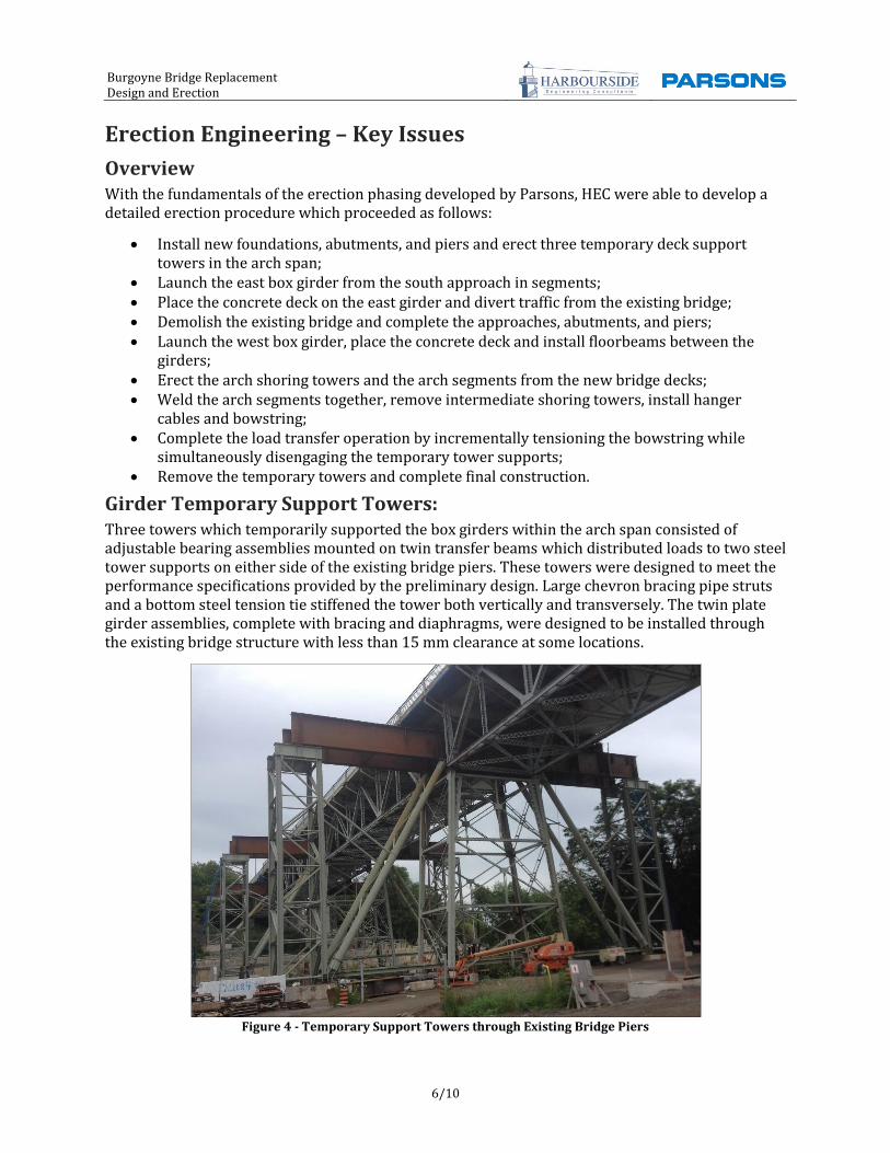
Girder Temporary Support Towers: Three towers which temporarily supported the box girders within the arch span consisted of adjustable bearing assemblies mounted on twin transfer beams which distributed loads to two steel tower supports on either side of the existing bridge piers. These towers were designed to meet the performance specifications provided by the preliminary design. Large chevron bracing pipe struts and a bottom steel tension tie stiffened the tower both vertically and transversely. The twin plate girder assemblies, complete with bracing and diaphragms, were designed to be installed through the existing bridge structure with less than 15 mm clearance at some locations.
Figure 4 - Temporary Support Towers through Existing Bridge Piers

Burgoyne Bridge Replacement Design and Erection
7/10
HEC designed a multi-purpose steel bearing and restraint assembly to support the box girders at each temporary support tower location during all phases of construction, from the initial launch of the box girders to the jack down phase which transferred the deck load from the towers to the hangers and arch.
Launching the Girders The box girders had to be erected with minimal disruptions to traffic on the existing Burgoyne Bridge and the Highway 406, while maintaining stable slopes in front of the north and south abutments. Erecting the box girders using a traditional “stick build” method would require positioning crawler cranes adjacent to the bridge on the approach slopes, along the banks of the Twelve Mile Creek, across Highway 406, and overtop existing underground utilities. Instead, HEC developed an innovative girder launching technique that allowed individual box girder segments to be delivered sequentially to the south approach where they were fit-up with adjacent box girder segments and launched across the bridge piers until they reached to the north abutment, eliminating the use of cranes during girder erection.
The girder launching system consisted of approach girder lifting frames, pull frames, and ballasting. The approach girder lifting frames were adjustable height frames founded on concrete spread footings which supported the box girder segments on the south approach during the girder launch. The pull frame consisted of a single strand jack connected to the south abutment that pulled the girder through the approach launch frames. The girder launch operation required the use of counterweights to maintain stability of the girders during the initial phases of the launch until multiple back-span sections of the girder were installed. Concrete blocks were placed on the launched girder on distributor beams and were designed such that an excavator, boom truck or small crane was able to install and remove the counterweights as required.
Figure 5 - View from South Approach Through the Box Girder Lifting Frames
Arch Shoring Towers: The arch was erected using five shoring towers supported on the girder support towers and on the girders themselves. HEC positioned the arch shoring towers to match the arch field splice locations,

Burgoyne Bridge Replacement Design and Erection
8/10
allowing them to double as access platforms for welding crews to complete the full penetration field welds for the arch chord splices. The shoring towers reached a height of 25 m from the top of the lower girder support towers (46 m above ground) and were designed with bolted connections to allow for easy dismantling after the arch was self-supporting. HEC designed the shoring towers to provide vertical and lateral support to the arch segments throughout their construction, and designed the supports to be fully adjustable to allow the precise fit-up of the arch segments for welding.
Figure 6 - Arch Shoring Towers Supporting Arch Structure
The intermediate arch shoring towers were supported on the new deck system. To prevent damaging the coatings of the permanent transverse floor beams and eliminate costly welding procedures, HEC designed a clamp and elastomeric pads bumper system.
The arch segments were erected by cranes positioned on the new bridge deck. Analysis of the bridge under construction loads ensured the crane loads would not damage the permanent structure. Once in place, the segments were aligned and supported at the shoring towers by the bottom chord underslung support system, which provided precise vertical, transverse and longitudinal adjustment for the arch segments. Field splice collars were installed to provide continuity between the segments for welding. HEC designed the system to connect to the permanent arch hanger lugs where possible, and to be fully adjustable for the transverse and longitudinal alignment of the arch segments during erection.
Figure 7 - Arch Segments Supported on Shoring Tower

Burgoyne Bridge Replacement Design and Erection
9/10
Installing the Hangers and Post Tensioning System Recognizing that the stiffness of the composite bridge deck made the hanger loads and deck profile highly sensitive to hanger lengths, HEC developed a hanger installation method which allowed the hangers to be installed precisely to their final length while the deck was supported on temporary supports. The hangers were then fully engaged simultaneously with the longitudinal post tensioning system during the load transfer procedures. HEC used finite element modelling (discussed below) to define a set of hanger lengths and a post tensioning procedure that achieved the target distribution of loads in the hangers as well as the final deck profile within 25 mm of the target over the 125 m span without additional adjustments.
Analytical Modelling HEC developed Finite Element (FE) models for the general construction phasing. Completing this modelling independently from the designer also allowed HEC to fully understand the behaviour of the bridge system during erection and in its final condition, and allowed HEC to efficiently modify erection procedures or adapt them to suit changing conditions. The FE models contained the bridge decks (in non-composite and composite stages), the permanent piers, the arch, the hangers and bowstring, arch shoring towers, and temporary support towers (see Figure 8). As the arch system is sensitive to soil-structure interactions at the pier foundations, a full geotechnical analysis was completed. These models were continually updated with measurements of site conditions.
One challenge encountered on this project, which HEC has found is typical for cable-supported structures, was simultaneously meeting tolerances in hanger loads while achieving the correct suspended deck profile. The high stiffness of the bridge girders with the composite concrete decks in place meant that the hanger lengths needed to be precisely established to ensure the correct distribution of loads. As-built dimensions and design changes which would affect the weight of the bridges decks had to be assessed during this process.
HEC developed an iterative modelling process of comparing the final output forces (FE model results) to the set of target forces (provided by the designer) and using an influence matrix of hanger adjustments to tune the hanger lengths accordingly. Using this method to calibrate the FE model ultimately allowed HEC to accurately define hanger installation lengths which met the tolerances for target loads and bridge deck profile. From the results of this analysis of the final structure, HEC were then able to determine the procedure of depropping the arch span.
Figure 8 - Finite Element Model for Load Transfer Operations

Burgoyne Bridge Replacement Design and Erection
10/10
Acknowledgments
Harbourside Engineering Consultants and Parsons would like to thank the following organizations for their contribution to the success of this project:
Bride Architect: DTAH Wind Engineering: Rowan Williams Davies & Irwin Inc General Contractor: Pomerleau Construction Bridge Owner: Regional Municipality of Niagara Steel Erector: Walters Inc. Steel Fabricators: Structal (box girders), Walters Inc. (temporary works and arch) Cable Supplier: VSL International Ltd. Bridge Demolition: Groupe - HBT
Figure 9 - Erection of Final Arch Segment