bureau of materials & research miscellaneous problem solving
TRANSCRIPT
BUREAU OF MATERIALS & RESEARCH
MISCELLANEOUS PROBLEM SOLVING No. MPS 2003-01
Evaluation of Steel H-Pile Points Final Report February 2009
DISCLAIMER
This document is disseminated under the sponsorship of the New Hampshire Department of Transportation (NHDOT) and the U.S. Department of Transportation, Federal Highway Administration (FHWA) in the interest of information exchange. The NHDOT and FHWA assume no liability for the use of information contained in this report. The document does not constitute a standard, specification, or regulation. The NHDOT and FHWA do not endorse products, manufacturers, engineering firms, or software. Products, manufacturers, engineering firms, software or other proprietary trade names appearing in this report are included only because they are considered essential to the objectives of the document.
ACKNOWLEDGEMENTS The author would like to thank the NHDOT Construction Bureau, particularly Contract Administrator Jim Hersey, for contributions to this evaluation including coordinating the installation and removal of the test piles and providing a site at which to do the evaluation, and Tom Cleary of the NHDOT Geotechnical Section, who performed the Pile Dynamic Analyzer testing of the piles and reviewed this report. Thanks also to E.D.Swett Inc., for preparing, driving, and extracting the test piles, specifically E.D. Swett co-owner Mike Cole and pile foreman Freddy.
INTRODUCTION
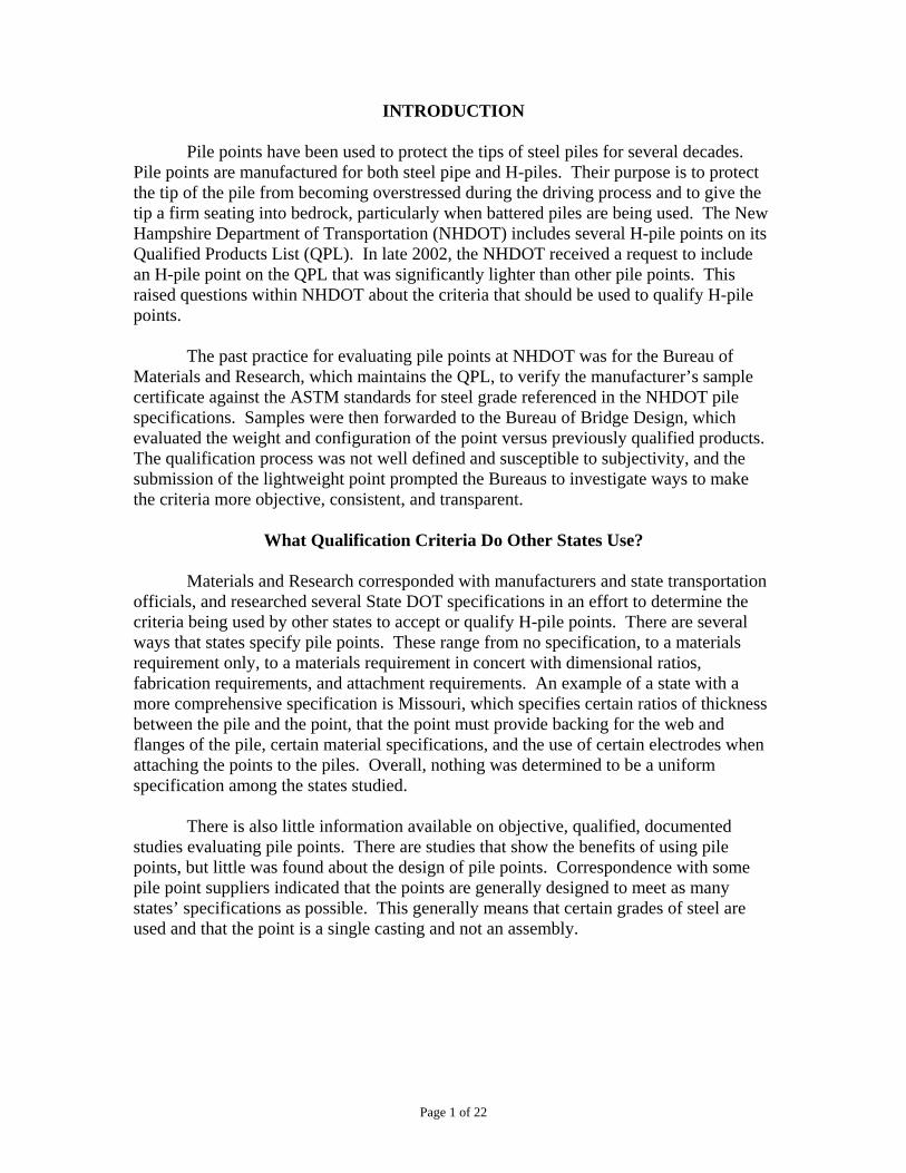
Pile points have been used to protect the tips of steel piles for several decades.
Pile points are manufactured for both steel pipe and H-piles. Their purpose is to protect the tip of the pile from becoming overstressed during the driving process and to give the tip a firm seating into bedrock, particularly when battered piles are being used. The New Hampshire Department of Transportation (NHDOT) includes several H-pile points on its Qualified Products List (QPL). In late 2002, the NHDOT received a request to include an H-pile point on the QPL that was significantly lighter than other pile points. This raised questions within NHDOT about the criteria that should be used to qualify H-pile points.
The past practice for evaluating pile points at NHDOT was for the Bureau of Materials and Research, which maintains the QPL, to verify the manufacturer’s sample certificate against the ASTM standards for steel grade referenced in the NHDOT pile specifications. Samples were then forwarded to the Bureau of Bridge Design, which evaluated the weight and configuration of the point versus previously qualified products. The qualification process was not well defined and susceptible to subjectivity, and the submission of the lightweight point prompted the Bureaus to investigate ways to make the criteria more objective, consistent, and transparent.
What Qualification Criteria Do Other States Use?
Materials and Research corresponded with manufacturers and state transportation officials, and researched several State DOT specifications in an effort to determine the criteria being used by other states to accept or qualify H-pile points. There are several ways that states specify pile points. These range from no specification, to a materials requirement only, to a materials requirement in concert with dimensional ratios, fabrication requirements, and attachment requirements. An example of a state with a more comprehensive specification is Missouri, which specifies certain ratios of thickness between the pile and the point, that the point must provide backing for the web and flanges of the pile, certain material specifications, and the use of certain electrodes when attaching the points to the piles. Overall, nothing was determined to be a uniform specification among the states studied.
There is also little information available on objective, qualified, documented studies evaluating pile points. There are studies that show the benefits of using pile points, but little was found about the design of pile points. Correspondence with some pile point suppliers indicated that the points are generally designed to meet as many states’ specifications as possible. This generally means that certain grades of steel are used and that the point is a single casting and not an assembly.
Page 1 of 22
OBJECTIVE
The lack of clear guidance on qualification criteria for pile points led the NHDOT to conduct a pile point testing program to gain first-hand knowledge about the field performance of pile points listed on the QPL.
APPROACH To evaluate the durability and performance of the pile points, piles fitted with points of various designs were driven in an area of known shallow bedrock. The testing was included as a work item on a scheduled construction project in order to minimize the cost of the research. It was hypothesized that a ratio comparing the weight of the point to its thickness could be an indicator of its performance. The field test was planned to test pile points representing each of four weight/thickness ratio and steel grade combinations. The four combinations were high weight/thickness ratio-high strength steel (HWT-HS), low weight/thickness ratio-high strength steel (LWT-HS), high weight/thickness ratio-low strength steel (HWT-LS), and low weight/thickness ratio-low strength steel (LWT-LS).
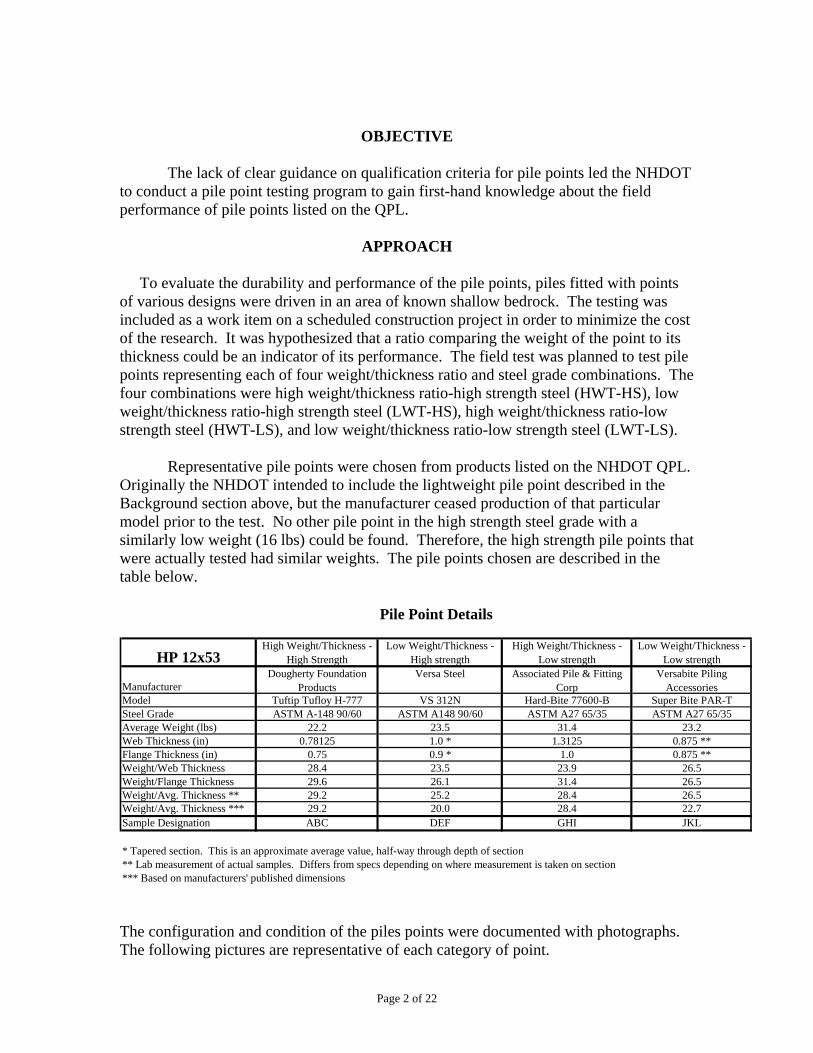
Representative pile points were chosen from products listed on the NHDOT QPL. Originally the NHDOT intended to include the lightweight pile point described in the Background section above, but the manufacturer ceased production of that particular model prior to the test. No other pile point in the high strength steel grade with a similarly low weight (16 lbs) could be found. Therefore, the high strength pile points that were actually tested had similar weights. The pile points chosen are described in the table below.
ManufacturerDougherty Foundation
ProductsVersa Steel Associated Pile & Fitting
CorpVersabite Piling
AccessoriesModel Tuftip Tufloy H-777 VS 312N Hard-Bite 77600-B Super Bite PAR-TSteel Grade ASTM A-148 90/60 ASTM A148 90/60 ASTM A27 65/35 ASTM A27 65/35Average Weight (lbs) 22.2 23.5 31.4 23.2Web Thickness (in) 0.78125 1.0 * 1.3125 0.875 **Flange Thickness (in) 0.75 0.9 * 1.0 0.875 **Weight/Web Thickness 28.4 23.5 23.9 26.5Weight/Flange Thickness 29.6 26.1 31.4 26.5Weight/Avg. Thickness ** 29.2 25.2 28.4 26.5Weight/Avg. Thickness *** 29.2 20.0 28.4 22.7Sample Designation ABC DEF GHI JKL
* Tapered section. This is an approximate average value, half-way through depth of section** Lab measurement of actual samples. Differs from specs depending on where measurement is taken on section*** Based on manufacturers' published dimensions
High Weight/Thickness - High Strength
High Weight/Thickness - Low strength
Low Weight/Thickness - Low strength
Pile Point Details
HP 12x53Low Weight/Thickness -
High strength
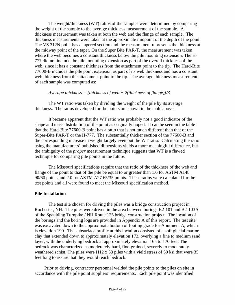
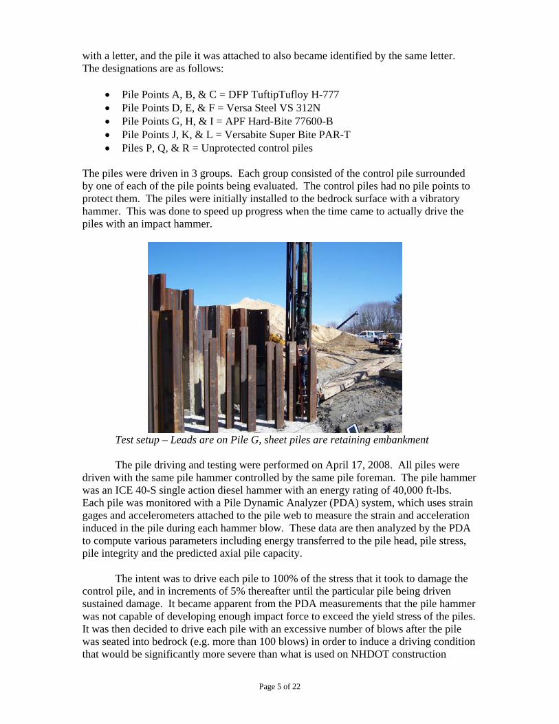
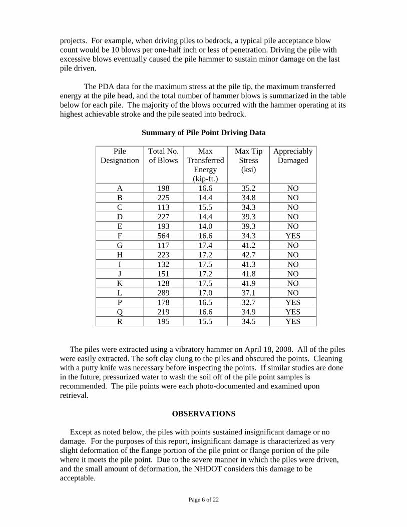
The configuration and condition of the piles points were documented with photographs. The following pictures are representative of each category of point.
Page 2 of 22
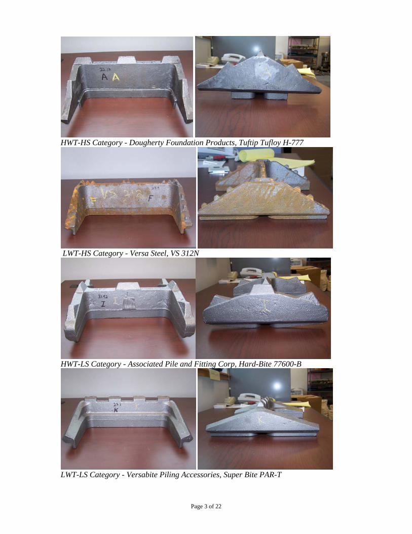
HWT-HS Category - Dougherty Foundation Products, Tuftip Tufloy H-777
LWT-HS Category - Versa Steel, VS 312N
HWT-LS Category - Associated Pile and Fitting Corp, Hard-Bite 77600-B
LWT-LS Category - Versabite Piling Accessories, Super Bite PAR-T
Page 3 of 22
The weight/thickness (WT) ratios of the samples were determined by comparing the weight of the sample to the average thickness measurement of the sample. A thickness measurement was taken at both the web and the flange of each sample. The thickness measurements were taken at the approximate midpoint of the depth of the point. The VS 312N point has a tapered section and the measurement represents the thickness at the midway point of the taper. On the Super Bite PAR-T, the measurement was taken where the web becomes a constant thickness below the pile mounting extension. The H-777 did not include the pile mounting extension as part of the overall thickness of the web, since it has a constant thickness from the attachment point to the tip. The Hard-Bite 77600-B includes the pile point extension as part of its web thickness and has a constant web thickness from the attachment point to the tip. The average thickness measurement of each sample was computed as: Average thickness = [thickness of web + 2(thickness of flange)]/3
The WT ratio was taken by dividing the weight of the pile by its average thickness. The ratios developed for the points are shown in the table above.
It became apparent that the WT ratio was probably not a good indicator of the shape and mass distribution of the point as originally hoped. It can be seen in the table that the Hard-Bite 77600-B point has a ratio that is not much different than that of the Super-Bite PAR-T or the H-777. The substantially thicker section of the 77600-B and the corresponding increase in weight largely even out the WT ratio. Calculating the ratio using the manufacturers’ published dimensions yields a more meaningful difference, but the ambiguity of the proper measurement technique suggests that WT is a flawed technique for comparing pile points in the future.
The Missouri specifications require that the ratio of the thickness of the web and flange of the point to that of the pile be equal to or greater than 1.6 for ASTM A148 90/60 points and 2.0 for ASTM A27 65/35 points. These ratios were calculated for the test points and all were found to meet the Missouri specification method. Pile Installation
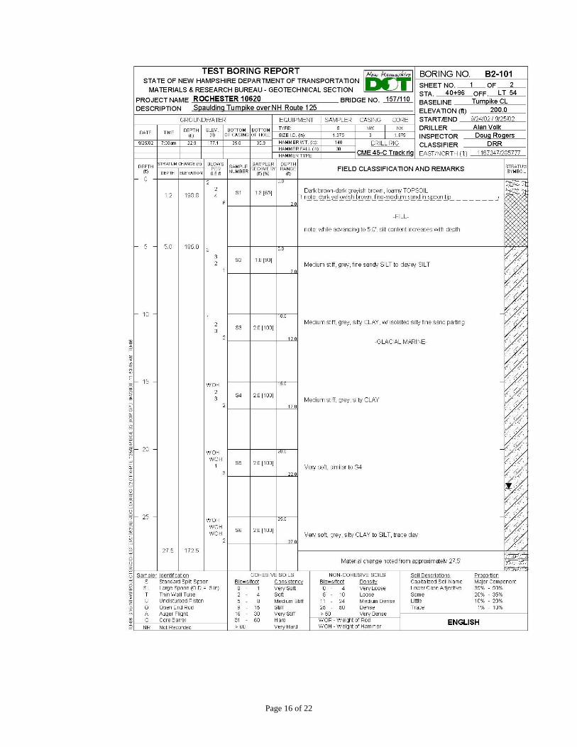
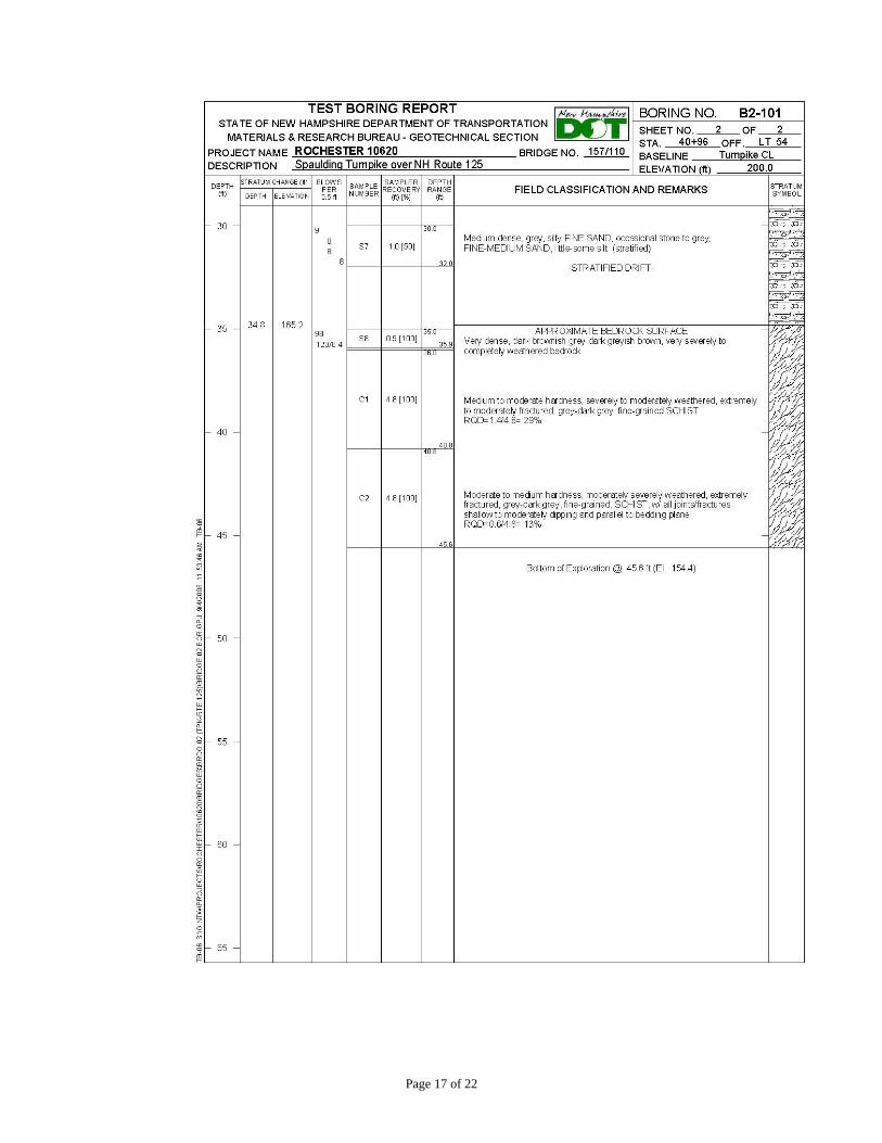
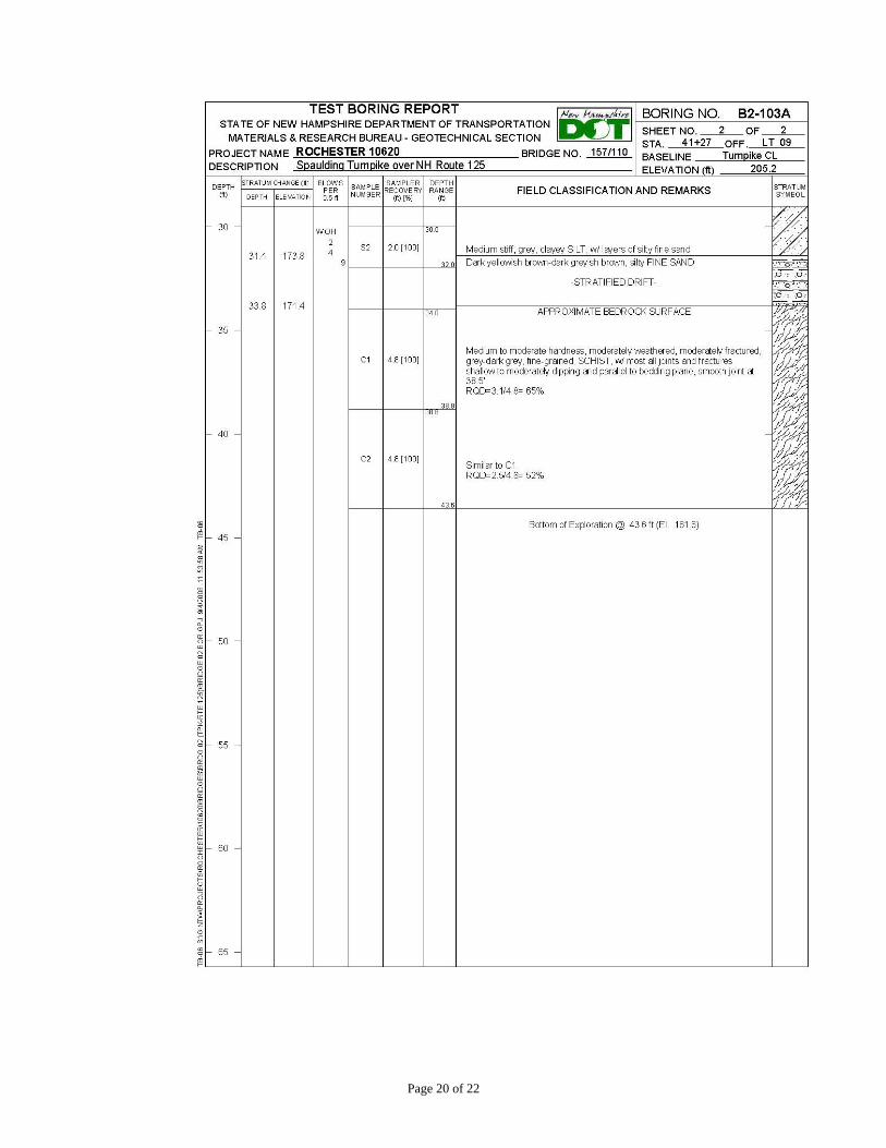
The test site chosen for driving the piles was a bridge construction project in Rochester, NH. The piles were driven in the area between borings B2-101 and B2-103A of the Spaulding Turnpike / NH Route 125 bridge construction project. The location of the borings and the boring logs are provided in Appendix A of this report. The test site was excavated down to the approximate bottom of footing grade for Abutment A, which is elevation 190. The subsurface profile at this location consisted of a soft glacial marine clay that extended down to approximately elevation 173, overlying a fine to medium sand layer, with the underlying bedrock at approximately elevation 165 to 170 feet. The bedrock was characterized as moderately hard, fine-grained, severely to moderately weathered schist. The piles were H12 x 53 piles with a yield stress of 50 ksi that were 35 feet long to assure that they would reach bedrock.
Prior to driving, contractor personnel welded the pile points to the piles on site in accordance with the pile point suppliers’ requirements. Each pile point was identified
Page 4 of 22
with a letter, and the pile it was attached to also became identified by the same letter. The designations are as follows:
• Pile Points A, B, & C = DFP TuftipTufloy H-777 • Pile Points D, E, & F = Versa Steel VS 312N • Pile Points G, H, & I = APF Hard-Bite 77600-B • Pile Points J, K, & L = Versabite Super Bite PAR-T • Piles P, Q, & R = Unprotected control piles
The piles were driven in 3 groups. Each group consisted of the control pile surrounded by one of each of the pile points being evaluated. The control piles had no pile points to protect them. The piles were initially installed to the bedrock surface with a vibratory hammer. This was done to speed up progress when the time came to actually drive the piles with an impact hammer.
Test setup – Leads are on Pile G, sheet piles are retaining embankment
The pile driving and testing were performed on April 17, 2008. All piles were driven with the same pile hammer controlled by the same pile foreman. The pile hammer was an ICE 40-S single action diesel hammer with an energy rating of 40,000 ft-lbs. Each pile was monitored with a Pile Dynamic Analyzer (PDA) system, which uses strain gages and accelerometers attached to the pile web to measure the strain and acceleration induced in the pile during each hammer blow. These data are then analyzed by the PDA to compute various parameters including energy transferred to the pile head, pile stress, pile integrity and the predicted axial pile capacity.
The intent was to drive each pile to 100% of the stress that it took to damage the control pile, and in increments of 5% thereafter until the particular pile being driven sustained damage. It became apparent from the PDA measurements that the pile hammer was not capable of developing enough impact force to exceed the yield stress of the piles. It was then decided to drive each pile with an excessive number of blows after the pile was seated into bedrock (e.g. more than 100 blows) in order to induce a driving condition that would be significantly more severe than what is used on NHDOT construction
Page 5 of 22
projects. For example, when driving piles to bedrock, a typical pile acceptance blow count would be 10 blows per one-half inch or less of penetration. Driving the pile with excessive blows eventually caused the pile hammer to sustain minor damage on the last pile driven.
The PDA data for the maximum stress at the pile tip, the maximum transferred energy at the pile head, and the total number of hammer blows is summarized in the table below for each pile. The majority of the blows occurred with the hammer operating at its highest achievable stroke and the pile seated into bedrock.
Summary of Pile Point Driving Data
Pile Designation
Total No. of Blows
Max Transferred
Energy (kip-ft.)
Max Tip Stress (ksi)
Appreciably Damaged
A 198 16.6 35.2 NO B 225 14.4 34.8 NO C 113 15.5 34.3 NO D 227 14.4 39.3 NO E 193 14.0 39.3 NO F 564 16.6 34.3 YES G 117 17.4 41.2 NO H 223 17.2 42.7 NO I 132 17.5 41.3 NO J 151 17.2 41.8 NO K 128 17.5 41.9 NO L 289 17.0 37.1 NO P 178 16.5 32.7 YES Q 219 16.6 34.9 YES R 195 15.5 34.5 YES
The piles were extracted using a vibratory hammer on April 18, 2008. All of the piles were easily extracted. The soft clay clung to the piles and obscured the points. Cleaning with a putty knife was necessary before inspecting the points. If similar studies are done in the future, pressurized water to wash the soil off of the pile point samples is recommended. The pile points were each photo-documented and examined upon retrieval.
OBSERVATIONS Except as noted below, the piles with points sustained insignificant damage or no damage. For the purposes of this report, insignificant damage is characterized as very slight deformation of the flange portion of the pile point or flange portion of the pile where it meets the pile point. Due to the severe manner in which the piles were driven, and the small amount of deformation, the NHDOT considers this damage to be acceptable.
Page 6 of 22
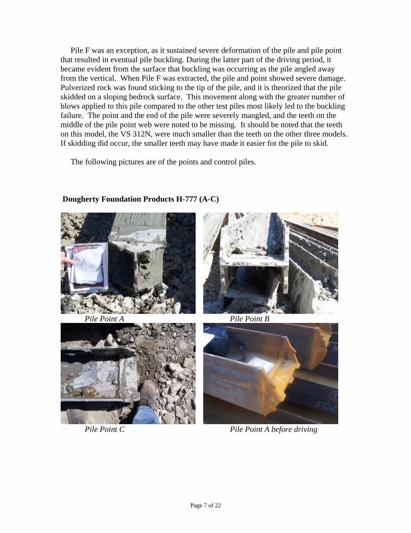
Pile F was an exception, as it sustained severe deformation of the pile and pile point that resulted in eventual pile buckling. During the latter part of the driving period, it became evident from the surface that buckling was occurring as the pile angled away from the vertical. When Pile F was extracted, the pile and point showed severe damage. Pulverized rock was found sticking to the tip of the pile, and it is theorized that the pile skidded on a sloping bedrock surface. This movement along with the greater number of blows applied to this pile compared to the other test piles most likely led to the buckling failure. The point and the end of the pile were severely mangled, and the teeth on the middle of the pile point web were noted to be missing. It should be noted that the teeth on this model, the VS 312N, were much smaller than the teeth on the other three models. If skidding did occur, the smaller teeth may have made it easier for the pile to skid. The following pictures are of the points and control piles. Dougherty Foundation Products H-777 (A-C)
Pile Point A Pile Point B
Pile Point C Pile Point A before driving
Page 7 of 22
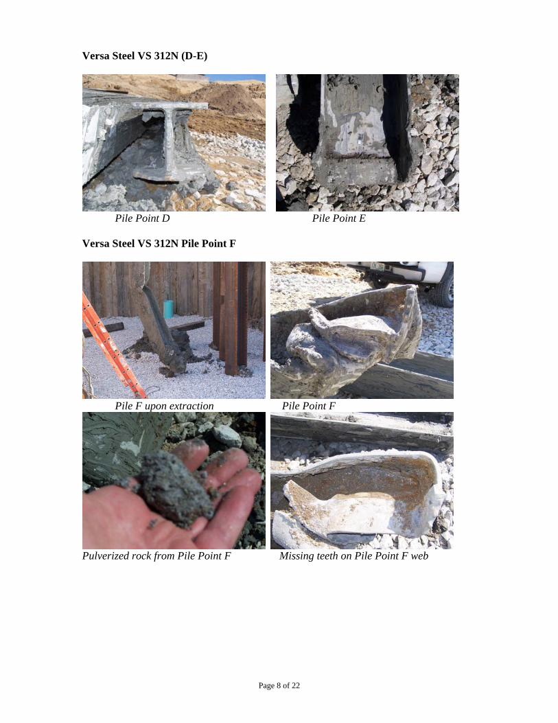
Versa Steel VS 312N (D-E)
Pile Point D Pile Point E
Versa Steel VS 312N Pile Point F
Pile F upon extraction Pile Point F
Pulverized rock from Pile Point F Missing teeth on Pile Point F web
Page 8 of 22
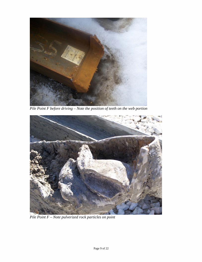
Pile Point F before driving – Note the position of teeth on the web portion
Pile Point F – Note pulverized rock particles on point
Page 9 of 22
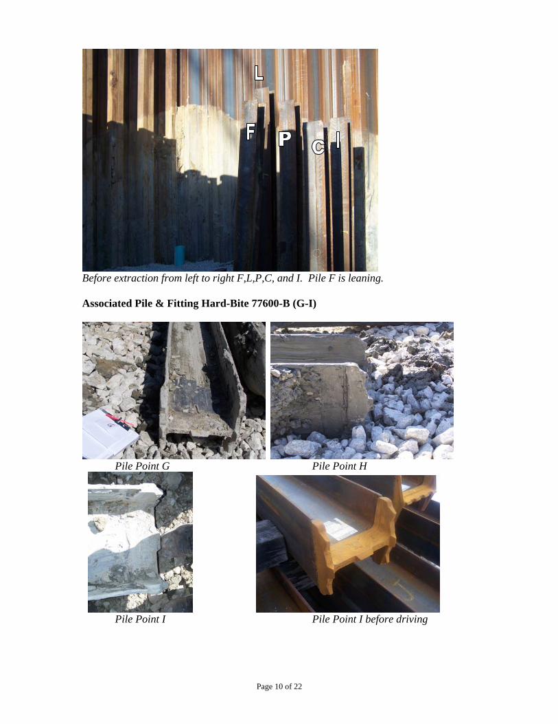
Before extraction from left to right F,L,P,C, and I. Pile F is leaning. Associated Pile & Fitting Hard-Bite 77600-B (G-I)
Pile Point G Pile Point H
Pile Point I Pile Point I before driving
Page 10 of 22
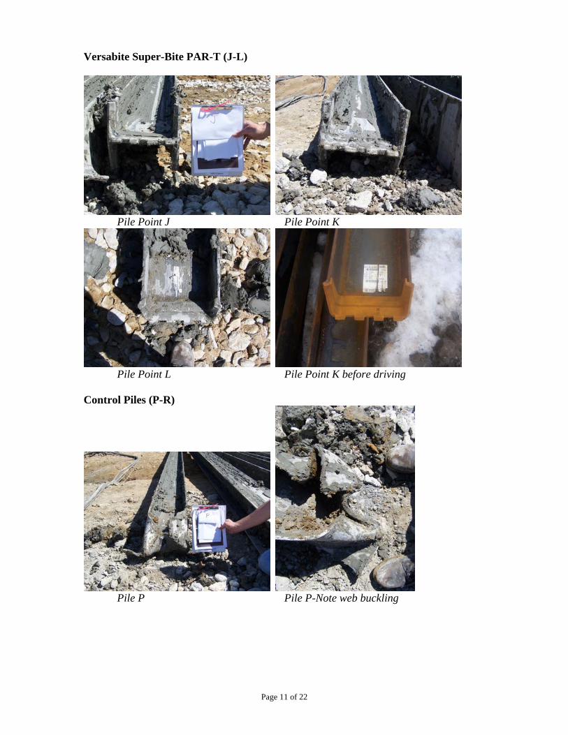
Versabite Super-Bite PAR-T (J-L)
Pile Point J Pile Point K
Pile Point L Pile Point K before driving
Control Piles (P-R)
Pile P Pile P-Note web buckling
Page 11 of 22
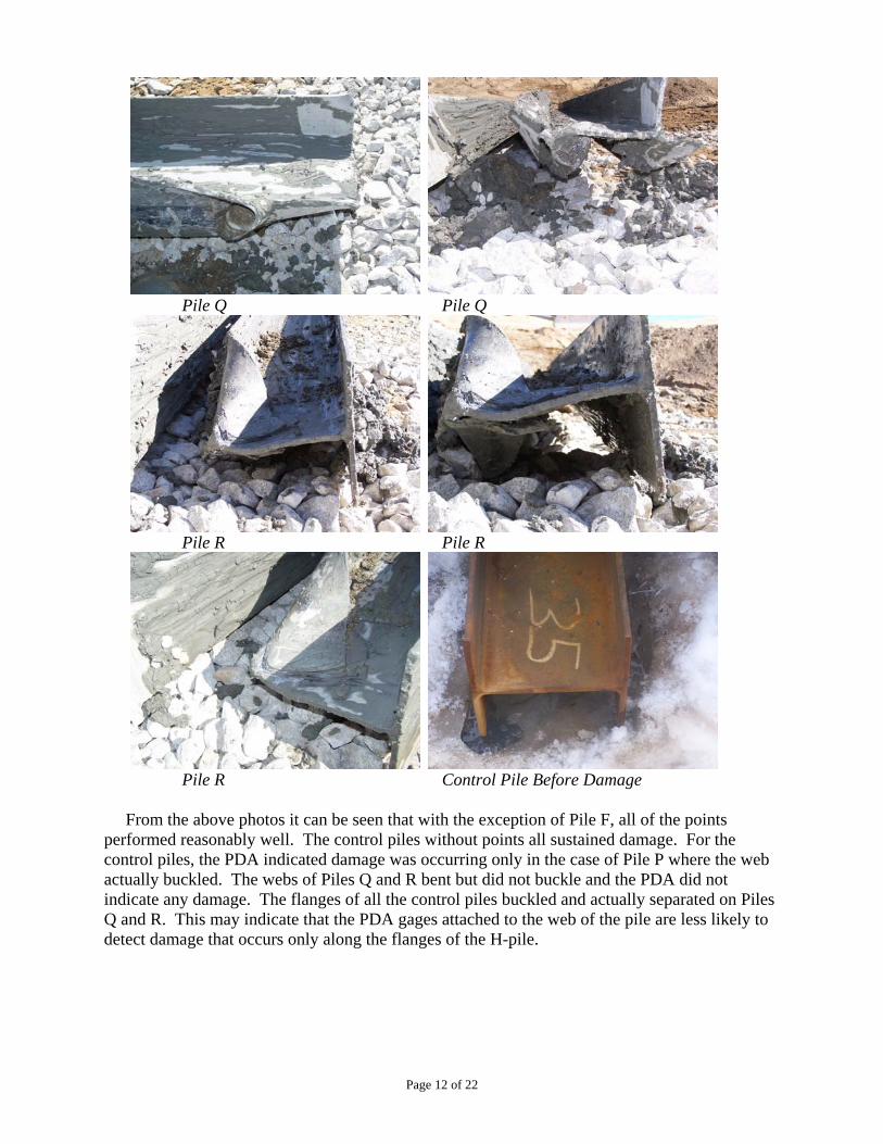
Pile Q Pile Q
Pile R Pile R
Pile R Control Pile Before Damage From the above photos it can be seen that with the exception of Pile F, all of the points performed reasonably well. The control piles without points all sustained damage. For the control piles, the PDA indicated damage was occurring only in the case of Pile P where the web actually buckled. The webs of Piles Q and R bent but did not buckle and the PDA did not indicate any damage. The flanges of all the control piles buckled and actually separated on Piles Q and R. This may indicate that the PDA gages attached to the web of the pile are less likely to detect damage that occurs only along the flanges of the H-pile.
Page 12 of 22
CONCLUSIONS AND RECOMMENDATIONS
• Pile point protection is necessary to minimize damage to end-bearing H-piles. The three unprotected control piles all sustained damage.
• The configuration (shape, taper, protrusions) of available pile point models vary significantly and make quantitative comparisons based on dimensional attributes difficult.
• While it is reasonable to require a minimum pile point thickness relative to the H-pile dimensions, the researchers concluded that a weight/thickness ratio is not a good indicator of performance. For some points, weight/thickness ratios are dependent on where the measurements are taken along the flange and/or the web. The weight/thickness ratios of the pile point samples used in the test did not correlate to any significant differences in the pile point configurations or to the results of the test. Pile Point F did fail, but the other two test samples of this product did not.
• The project indicated that, under the conditions of this test, pile point material strength did not correlate to any significant differences in performance. Perhaps under more severe conditions, material strength would be more critical. It is reasonable to require a minimum weight (e.g. 22 lbs) commensurate with the points evaluated during this field test.
• It is reasonable to specify minimum tooth requirements for pile points, particularly if a sloping bedrock surface is expected. This is due to the possibility that the Pile F failure was in part caused by the slippage of the pile on the bedrock surface. The optimum size, number, or configuration of pile point teeth was not determined.
• The PDA may not detect all damage to an H-pile, and the web of the H-pile may have to sustain some deformation before damage is indicated by the PDA.
Prepared By: Reviewed By: Andrew D. Hall, P.E. Glenn E. Roberts, P.E. Asst. Research Engineer Chief of Research
S:\Research\Research Projects\Miscellaneous - Problem Solving\MPS 2003-01 Pile Points\EVALUATION REPORT.doc
Page 13 of 22

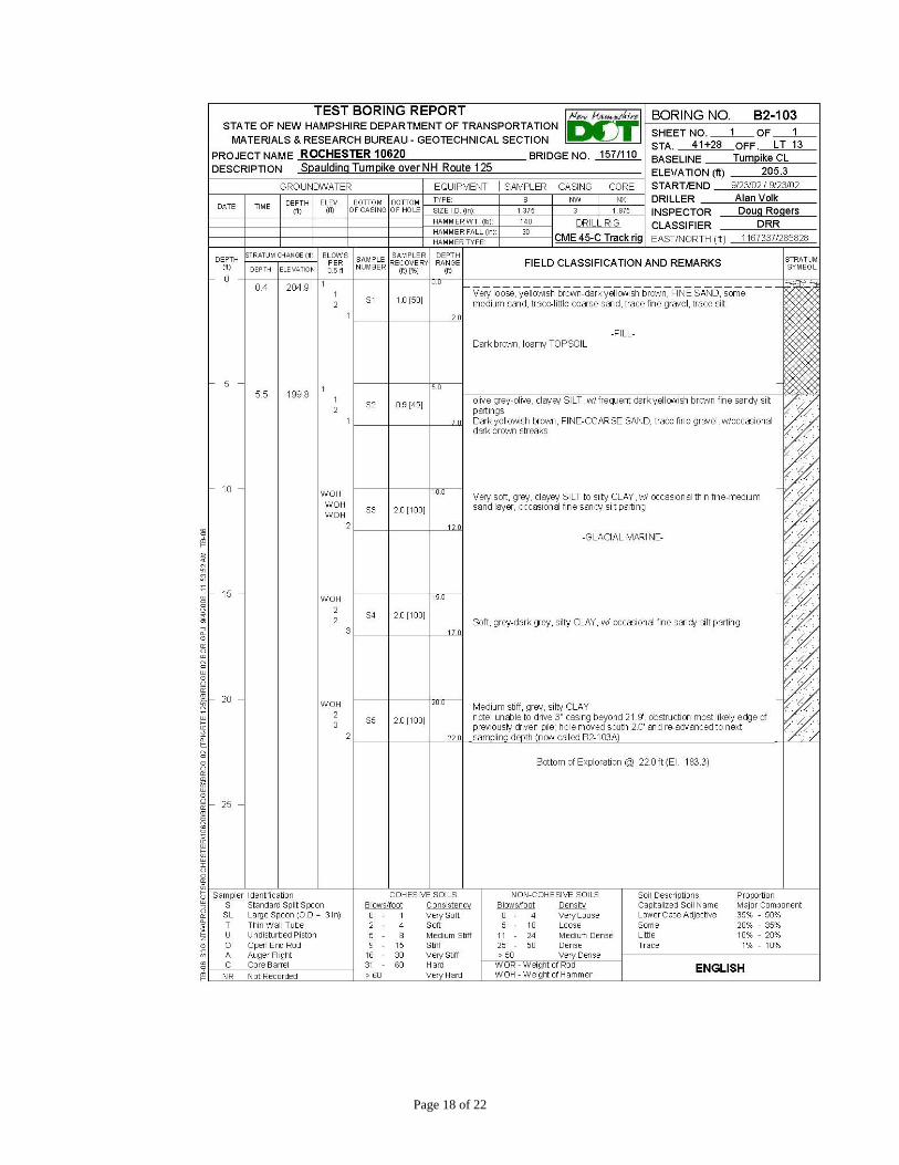
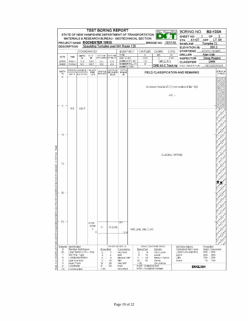
APPENDIX A Boring Logs
Page 14 of 22
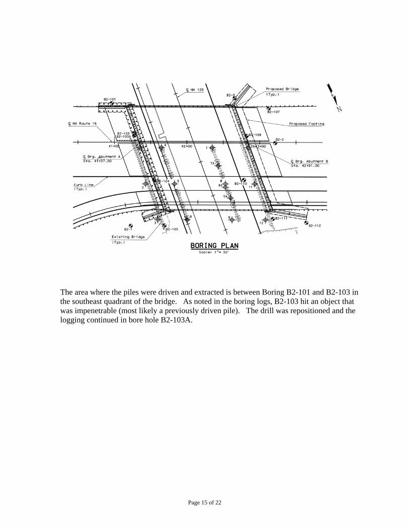
The area where the piles were driven and extracted is between Boring B2-101 and B2-103 in the southeast quadrant of the bridge. As noted in the boring logs, B2-103 hit an object that was impenetrable (most likely a previously driven pile). The drill was repositioned and the logging continued in bore hole B2-103A.
Page 15 of 22
Page 16 of 22
Page 17 of 22
Page 18 of 22
Page 19 of 22
Page 20 of 22