bunn technical training - bunn online learning...
TRANSCRIPT

BUNN® TECHNICAL TRAININGThermoFresh BrewWISE® DBC
Index
Unit 1: Installation
Site Requirements ..............................................................................................................4 Location of the Serial Number ..........................................................................................4 Water Supply Install ...........................................................................................................4 Electrical Install ..................................................................................................................5 Initial Start-Up .....................................................................................................................6
Unit 2: Setup Setup and Programming ....................................................................................................8 Programming Lockout .................................................................................................8 Level 1 Programming .........................................................................................................9 Level 2 Programming .........................................................................................................9 Level 3 Programming .........................................................................................................10 Calibrating Flow Rate .........................................................................................................10 Check and Adjust the Dispense Valve Flow Rate ..................................................... 10 Check and Adjust the Bypass Valve Flow Rate ........................................................ 11 Programming the Recipes .................................................................................................11 Calibrating the Temperature Sensing Probe ....................................................................12
Unit 3: Machine Composition
Exterior Overview ...............................................................................................................14 Product Outlets and Removable Parts ......................................................................14 User Interface ...............................................................................................................14 Accessing the Inside of the Brewer ..................................................................................14 Machine Function and Operations ....................................................................................15 Main Control Board ......................................................................................................15 Filling System ...............................................................................................................15 Heating System ............................................................................................................16 Dispensing System ......................................................................................................17 Coffee Holding System ................................................................................................17
Unit 4: Preventive Maintenance
Preventive Maintenance .....................................................................................................19 PM Steps .............................................................................................................................19
Unit 5: Troubleshooting
Service Tools ......................................................................................................................22 Test Outputs .................................................................................................................22 Test Switches ...............................................................................................................23 Test Frequency .............................................................................................................23 Service Fault Messages .....................................................................................................23 Operator Fault Messages ...................................................................................................24 Refill,Heating&BrewingTroublshooting ........................................................................25 Triac Map .............................................................................................................................29 Additional Resources .........................................................................................................30
© 2011 Bunn-O-Matic Corporation. All Rights ReservedRev. A

Unit Objectives
Unit 1 installation
Given a realistic scenario depicting a new site install, the learner will be able to install and setup the brewer for customer turnover without error.
Given a new machine, all the necessary tools and safety equipment, the learner will be able to install the brewer without error.
The learner will be able to verify that the site requirements have been met. The learner will be able to locate and document the serial number. The learner will be able to hook up the water supply. The learner will be able to hook up the electrical supply.
TF BrewWISE® Training Manual
4
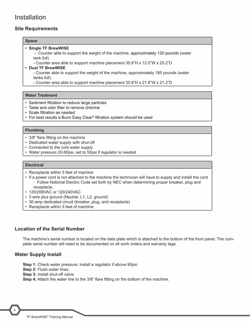
InstallationSite Requirements
Space
• Single TF BrewWISE - Counter able to support the weight of the machine, approximately 120 pounds (water tank full)- Counter area able to support machine placement 35.8”H x 12.5”W x 20.2”D
• Dual TF BrewWISE- Counter able to support the weight of the machine, approximately 185 pounds (water tanks full)- Counter area able to support machine placement 35.8”H x 21.8”W x 21.2”D
Water Treatment
• Sedimentfiltrationtoreducelargeparticles• Tasteandodorfiltertoremovechlorine• Scalefiltrationasneeded• For best results a Bunn Easy Clear®filtrationsystemshouldbeused
Plumbing
• 3/8”flarefittingonthemachine• Dedicated water supply with shut-off• Connected to the cold water supply• Water pressure 20-90psi, set to 50psi if regulator is needed
Electrical
• Receptacle within 5 feet of machine• If a power cord is not attached to the machine the technician will have to supply and install the cord
- Follow National Electric Code set forth by NEC when determining proper breaker, plug and receptacle.
• 120/208VAC or 120/240VAC• 3 wire plus ground (Neutral, L1, L2, ground)• 30 amp dedicated circuit (breaker, plug, and receptacle)• Receptacle within 5 feet of machine
Location of the Serial Number
The machine’s serial number is located on the data plate which is attached to the bottom of the front panel. The com-plete serial number will need to be documented on all work orders and warranty tags.
Water Supply Install
Step 1: Check water pressure, install a regulator if above 90psi.Step 2: Flush water lines.Step 3: Install shut-off valve.Step 4:Attachthewaterlinetothe3/8”flarefittingonthebottomofthemachine.

Bunn-O-Matic Corporation5
Electrical Install
Refer to the electrical section of the machine’s data plate to select the proper power cord, plug and receptacle for thebrewer.Anelectricianmustprovideelectricalserviceasspecifiedinconformancewithalllocal,state,andfederalelectrical codes.
Step 1:Removethefrontpanel(11flathead screws).Step 2: Feed the power cord through the strain relief in the bottom of the machine.Step 3: Attach the wire ends to the terminal block.Step 4: Attach the ground wire to connector on the frame cross bar.Step 5: Check that all connections are tight.Step 6: Tighten the strain relief and replace the front panel.Step 7: Plug the unit into the power source.
GREEN GREEN
L1, L2, L3, are the 3 phasesV1 = Phase to phase voltage, between any 2 phases.V2 = Phase to neutral voltage, L1 to neutral must be 120V.
SYSTEMVOLTAGE V1 V2 208 208 120 240 240 120
CAUTION: Do not connect L1 to a circuit operating at more than 150 volts to ground.
120/208 and 120/240 volt ac 3 phase & multi phase,
60 Hz models
Note: This electrical service consists of 4 current carrying conductors (Neutral, L1, L2 and L3) and a separate con-ductor for earth ground.
WHI
BLK
RED
BLUL3
L2
L1
N
120/208 and 120/240 volt acsingle phase, 60 Hz models
Note: This electrical service consists of 3 current carrying conductors (Neutral, L1 and L2) and a separate conductor for earth ground.
L2
N
L1
G
L2 RED
WHITE
GREEN GREEN
NEUTRALL1 BLACK
L2 RED
WHITE
NEUTRALL1 BLACK
TF BrewWISE® Training Manual
6
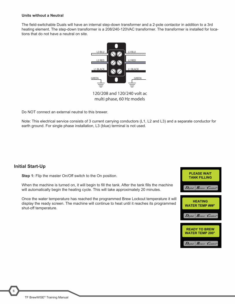
Units without a Neutral
Thefield-switchableDualswillhaveaninternalstep-downtransformeranda2-polecontactorinadditiontoa3rdheating element. The step-down transformer is a 208/240-120VAC transformer. The transformer is installed for loca-tions that do not have a neutral on site.
Initial Start-Up
Step 1: Flip the master On/Off switch to the On position.
Whenthemachineisturnedon,itwillbegintofillthetank.Afterthetankfillsthemachinewill automatically begin the heating cycle. This will take approximately 20 minutes.
Once the water temperature has reached the programmed Brew Lockout temperature it will display the ready screen. The machine will continue to heat until it reaches its programmed shut-off temperature.
PLEASE WAIT TANK FILLING
HEATING
READY TO BREW
WATER TEMP ###°
WATER TEMP 200°
200 and 230 volt acsingle phase, 60 Hz models
Note: This electrical service consists of 2 current carrying conductors (L1 and L2) and a separate conductor for earth ground.
L2 RED
200 or230V
GREEN
L1 BLACK
GREEN
120/208 and 120/240 volt acmulti phase, 60 Hz models
Do NOT connect an external neu-tral to this brewer.
Note: This electrical service con-sists of 3 current carrying conduc-tors (L1, L2 and L3) and a separate conductor for earth ground.
GREEN GREEN
L1 BLACK L1 BLACK
L3 BLU L3 BLU
L2 RED L2 RED
Do NOT connect an external neutral to this brewer.
Note: This electrical service consists of 3 current carrying conductors (L1, L2 and L3) and a separate conductor for earth ground. For single phase installation, L3 (blue) terminal is not used.

Unit Objectives
Unit 2 setup
Given a realistic scenario depicting a new site install, the learner will be able to install and setup the brewer for customer turnover without error.
Given an installed machine, all the necessary tools and safety equipment, the learner will be able to set the machine up for initial operation.
The learner will be able to power on the machine. The learner will be able to perform the calibrations.

TF BrewWISE® Training Manual
8
Setup and ProgrammingThe BrewWISE® software is the latest evolution of BUNN’s digital brewer control (DBC®) system. The software al-lows precise brewing control and multiple extraction recipes to be stored on the brewer and onboard troubleshooting capabilities for the technician. The software also allows the brewer to communicate with a DBC® grinder, to reduce operator errors when selecting products and batch sizes.
Accessing and using the brewer’s programming features is done from the front panel and requires no special tools.
The programming menu is accessed by pressing the hidden switch, located under the trademark symbol, on the right side of the Bunn logo. The hidden switch on the left side will allow you to scroll backwards.
Right Hidden Switch: This is used to access the programming mode and is also used to scroll forward through the function list.
Left Hidden Switch: This is used to scroll backwards through the function list.
Digital (lower left under the display): This is used to select options that appear on the display during programming.
Brewer (center under the display): This is used to select options that appear on the display during programming.
Control (lower right under the display): This is used to select options that appear on the display during programming.
Programming Lockout
While the programming lockout switch is in the On position, the programming menus cannot be accessed. The switch is located on the control board. Remove the top panel, locate the switch and place it into the Enable position.
ENABLE
ON / OFFBREW
ENABLE
ON / OFFBREW
Right Hidden SwitchLeft Hidden Switch
Digital Brewer Control
Program LockoutSwitch
Bunn-O-Matic Corporation9
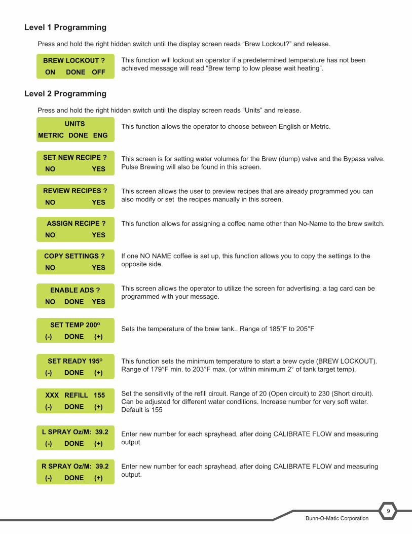
Level 1 Programming
Press and hold the right hidden switch until the display screen reads “Brew Lockout?” and release.
This function will lockout an operator if a predetermined temperature has not been achieved message will read “Brew temp to low please wait heating”.
Level 2 Programming
Press and hold the right hidden switch until the display screen reads “Units” and release.
This function allows the operator to choose between English or Metric.
This screen is for setting water volumes for the Brew (dump) valve and the Bypass valve. Pulse Brewing will also be found in this screen.
This screen allows the user to preview recipes that are already programmed you can also modify or set the recipes manually in this screen.
This function allows for assigning a coffee name other than No-Name to the brew switch.
If one NO NAME coffee is set up, this function allows you to copy the settings to the opposite side.
This screen allows the operator to utilize the screen for advertising; a tag card can be programmed with your message.
Sets the temperature of the brew tank.. Range of 185°F to 205°F
This function sets the minimum temperature to start a brew cycle (BREW LOCKOUT). Range of 179°F min. to 203°F max. (or within minimum 2° of tank target temp).
Setthesensitivityoftherefillcircuit.Rangeof20(Opencircuit)to230(Shortcircuit). Can be adjusted for different water conditions. Increase number for very soft water. Default is 155
Enter new number for each sprayhead, after doing CALIBRATE FLOW and measuring output.
Enter new number for each sprayhead, after doing CALIBRATE FLOW and measuring output.
SET TEMP 200O
(-) (+)DONE
SET READY 195O
(-) (+)DONE
XXX REFILL 155(-) (+)DONE
L SPRAY Oz/M: 39.2(-) (+)DONE
R SPRAY Oz/M: 39.2(-) (+)DONE
BREW LOCKOUT ?ON OFFDONE
SET NEW RECIPE ?NO YES
REVIEW RECIPES ?NO YES
ENABLE ADS ?NO YESDONE
UNITSMETRIC ENG DONE
ASSIGN RECIPE ?NO YES
COPY SETTINGS ?NO YES
TF BrewWISE® Training Manual
10
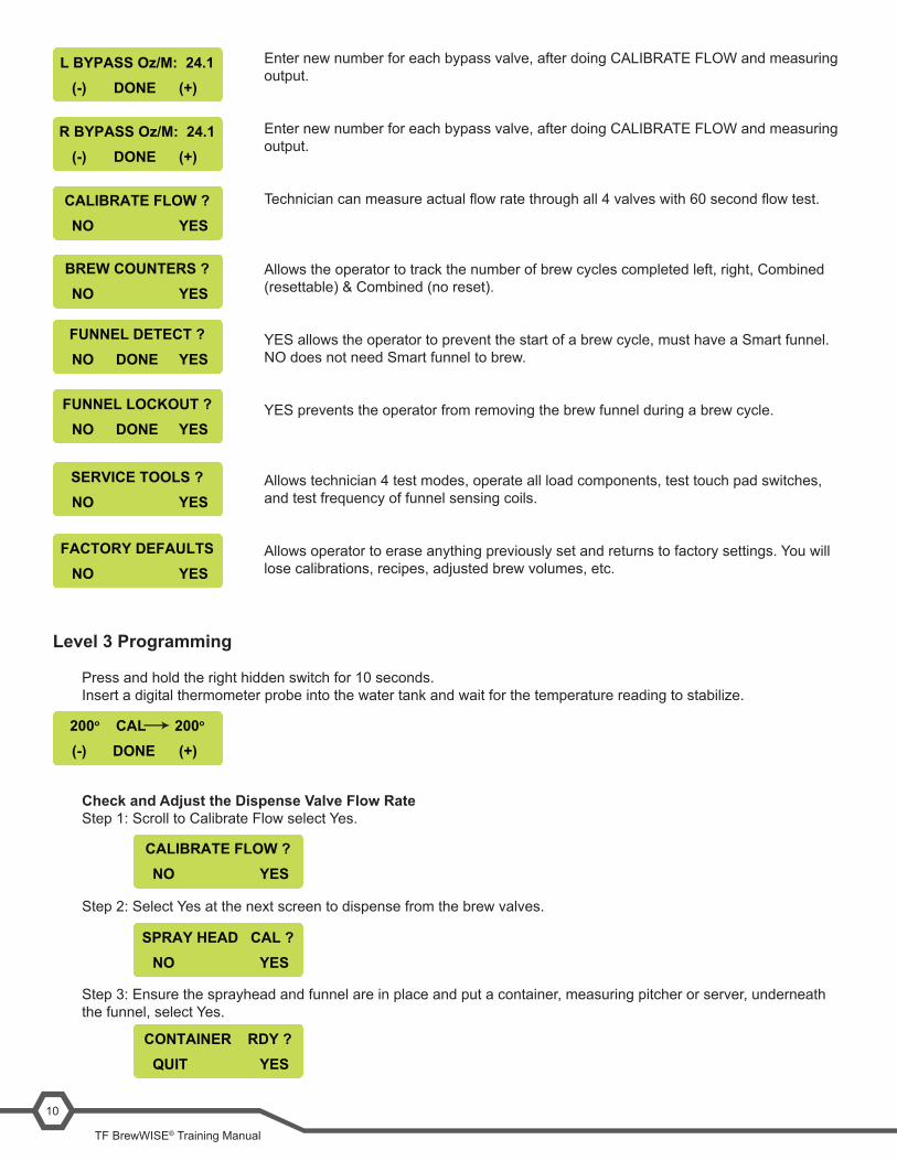
Enter new number for each bypass valve, after doing CALIBRATE FLOW and measuring output.
Enter new number for each bypass valve, after doing CALIBRATE FLOW and measuring output.
Techniciancanmeasureactualflowratethroughall4valveswith60secondflowtest.
Allows the operator to track the number of brew cycles completed left, right, Combined (resettable) & Combined (no reset).
YES allows the operator to prevent the start of a brew cycle, must have a Smart funnel. NO does not need Smart funnel to brew.
YES prevents the operator from removing the brew funnel during a brew cycle.
Allows technician 4 test modes, operate all load components, test touch pad switches, and test frequency of funnel sensing coils.
Allows operator to erase anything previously set and returns to factory settings. You will lose calibrations, recipes, adjusted brew volumes, etc.
Level 3 Programming
Press and hold the right hidden switch for 10 seconds.Insert a digital thermometer probe into the water tank and wait for the temperature reading to stabilize.
Check and Adjust the Dispense Valve Flow RateStep 1: Scroll to Calibrate Flow select Yes.
Step 2: Select Yes at the next screen to dispense from the brew valves.
Step 3: Ensure the sprayhead and funnel are in place and put a container, measuring pitcher or server, underneath the funnel, select Yes.
SERVICE TOOLS ?NO YES
FACTORY DEFAULTSNO YES
200o CAL 200o
(-) (+)DONE
CALIBRATE FLOW ?NO YES
SPRAY HEAD CAL ?NO YES
CONTAINER RDY ?QUIT YES
R BYPASS Oz/M: 24.1(-) (+)DONE
CALIBRATE FLOW ?NO YES
BREW COUNTERS ?NO YES
FUNNEL LOCKOUT ?NO DONE YES
L BYPASS Oz/M: 24.1(-) (+)DONE
FUNNEL DETECT ?NO DONE YES
Bunn-O-Matic Corporation11
LEFT OZ 36.0QUIT YES
CALIBRATE FLOW ?NO YES
SPRAY HEAD CAL ?NO YES
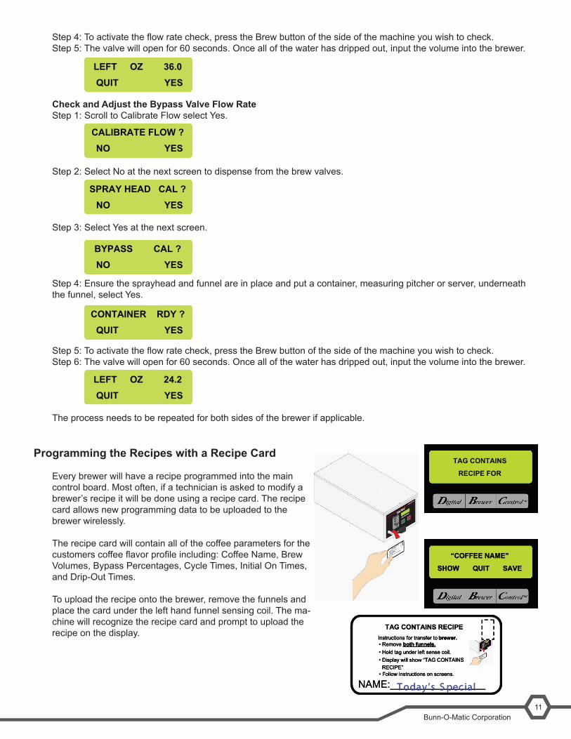
Step4:Toactivatetheflowratecheck,presstheBrewbuttonofthesideofthemachineyouwishtocheck.Step 5: The valve will open for 60 seconds. Once all of the water has dripped out, input the volume into the brewer.
Check and Adjust the Bypass Valve Flow RateStep 1: Scroll to Calibrate Flow select Yes.
Step 2: Select No at the next screen to dispense from the brew valves.
Step 3: Select Yes at the next screen.
Step 4: Ensure the sprayhead and funnel are in place and put a container, measuring pitcher or server, underneath the funnel, select Yes.
Step5:Toactivatetheflowratecheck,presstheBrewbuttonofthesideofthemachineyouwishtocheck.Step 6: The valve will open for 60 seconds. Once all of the water has dripped out, input the volume into the brewer.
The process needs to be repeated for both sides of the brewer if applicable.
Programming the Recipes with a Recipe Card
Every brewer will have a recipe programmed into the main control board. Most often, if a technician is asked to modify a brewer’s recipe it will be done using a recipe card. The recipe card allows new programming data to be uploaded to the brewer wirelessly.
The recipe card will contain all of the coffee parameters for the customerscoffeeflavorprofileincluding:CoffeeName,BrewVolumes, Bypass Percentages, Cycle Times, Initial On Times, and Drip-Out Times.
To upload the recipe onto the brewer, remove the funnels and place the card under the left hand funnel sensing coil. The ma-chine will recognize the recipe card and prompt to upload the recipe on the display.
TAG CONTAINS
RECIPE FOR
“COFFEE NAME”
SHOW QUIT SAVE
“COFFEE NAME”
SHOW QUIT SAVE
NAME:_________________
TAG CONTAINS RECIPEInstructions for transfer to brewer.• Remove both funnels.• Hold tag under left sense coil.• Display will show “TAG CONTAINSRECIPE”• Follow instructions on screens.
T oday’s S pec ialNAME:_________________
TAG CONTAINS RECIPEInstructions for transfer to brewer.• Remove both funnels.• Hold tag under left sense coil.• Display will show “TAG CONTAINSRECIPE”• Follow instructions on screens.
Instructions for transfer to brewer.• Remove both funnels.• Hold tag under left sense coil.• Display will show “TAG CONTAINSRECIPE”• Follow instructions on screens.
T oday’s S pec ial
BYPASS CAL ?NO YES
CONTAINER RDY ?QUIT YES
LEFT OZ 24.2QUIT YES
TF BrewWISE® Training Manual
12
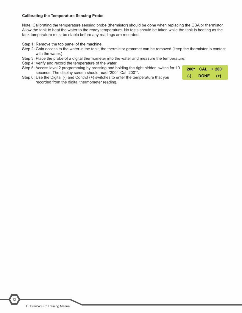
Calibrating the Temperature Sensing Probe
Note: Calibrating the temperature sensing probe (thermistor) should be done when replacing the CBA or thermistor.Allow the tank to heat the water to the ready temperature. No tests should be taken while the tank is heating as the tank temperature must be stable before any readings are recorded.
Step 1: Remove the top panel of the machine.Step 2: Gain access to the water in the tank, the thermistor grommet can be removed (keep the thermistor in contact with the water.)Step 3: Place the probe of a digital thermometer into the water and measure the temperature.Step 4: Verify and record the temperature of the water.Step 5: Access level 2 programming by pressing and holding the right hidden switch for 10 seconds. The display screen should read “200° Cal 200°”.Step 6: Use the Digital (-) and Control (+) switches to enter the temperature that you recorded from the digital thermometer reading.
200o CAL 200o
(-) (+)DONE
Unit Objectives
Unit 3 Machine coMposition
Given a realistic scenario in which the learner has access to the machine’s internal components the learner will understand the composition and functions of the brewer.
Given a realistic scenario requiring the learner to access the internal components of the machine the learner will be able to remove the front panel and top cover.
The learner will disconnect the electrical and water supply. The learner will remove the front panel and top cover.
Given an operating machine the learner will be able to give a general explanation of how the unit operates.
The learner will be able to identify the functions of the main control board and identify the components that correspond to each triac. Thelearnerwillbeabletoidentifythecomponentsandfunctionsofthefillingsystem. The learner will be able to identify the components and functions of the heating system. The learner will be able to identify the components and functions of the dispensing system. The learner will be able to identify the components and functions of the coffee holding system.

TF BrewWISE® Training Manual
14
Machine Composition
Exterior Overview
Product Outlets and Removable Parts
• User interface (1)• Display (mounted to the control board) (2)• Hot water outlet (3)• Funnel sensing coil (4)• Funnel (5)• Server (6)• Data plate (7)
User Interface
The user interface is a membrane switch adhered to the front of the brewer. The membrane is connected to the con-trol board by a ribbon cable. The user interface allows the user to select product size and begin a brew cycle.
The machine’s display is mounted to the control board. The display is visible on the front of the machine and provides information to the user and to the technician.
Accessing the Inside of the Brewer
The majority of service work done to the BrewWISE® brewer will require the service technician to access the inside of the unit. The brewer has three removable panels to facilitate access- the front panel, the top panel, and the server base panel. Depending on the repair the technician may have to remove one or all of these panels.
In order to work safely the power should be disconnected prior to removal of any body panel. Once the panels are removed the power can be reconnected in order to troubleshoot the machine.
Thetoppanelissecuredwith4smallflatheadscrews.Totheremovethepanel,removethefourscrews,liftthefrontof the panel up and slide the rear backwards to unhook the panel from the brewer’s body.Toremovethefrontpanel,firstremovethefunnelsandserversfromthemachine.Thefrontpanelissecuredtothebrewer with 11 standard screws. Remove the screws and pull the panel straight off of the unit.
1 2
3
4
5
6
7
Batch Selector Switches
On/Off Switch
Brew Start Switch
Funnel Sensing Coils
ENABLE
ON / OFFBREW
ENABLE
ON / OFFBREW
Bunn-O-Matic Corporation15
Machine Function and Operations
Main Control Board
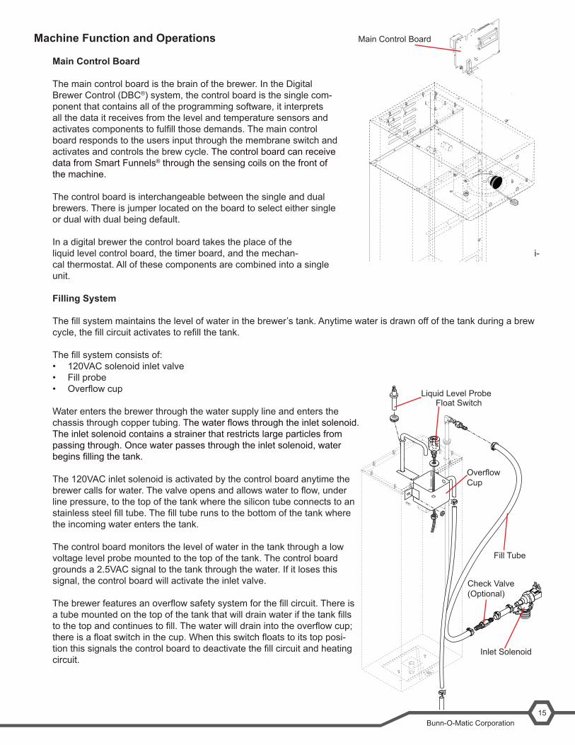
The main control board is the brain of the brewer. In the Digital Brewer Control (DBC®) system, the control board is the single com-ponent that contains all of the programming software, it interprets all the data it receives from the level and temperature sensors and activatescomponentstofulfillthosedemands.Themaincontrolboard responds to the users input through the membrane switch and activates and controls the brew cycle. The control board can receive data from Smart Funnels® through the sensing coils on the front of the machine.
The control board is interchangeable between the single and dual brewers. There is jumper located on the board to select either single or dual with dual being default.
In a digital brewer the control board takes the place of the liquid level control board, the timer board, and the mechan- i-cal thermostat. All of these components are combined into a single unit.
Filling System
Thefillsystemmaintainsthelevelofwaterinthebrewer’stank.Anytimewaterisdrawnoffofthetankduringabrewcycle,thefillcircuitactivatestorefillthetank.
Thefillsystemconsistsof:• 120VAC solenoid inlet valve• Fill probe• Overflowcup
Water enters the brewer through the water supply line and enters the chassis through copper tubing.Thewaterflowsthroughtheinletsolenoid.The inlet solenoid contains a strainer that restricts large particles from passing through. Once water passes through the inlet solenoid, water beginsfillingthetank.
The 120VAC inlet solenoid is activated by the control board anytime the brewercallsforwater.Thevalveopensandallowswatertoflow,underline pressure, to the top of the tank where the silicon tube connects to an stainlesssteelfilltube.Thefilltuberunstothebottomofthetankwherethe incoming water enters the tank.
The control board monitors the level of water in the tank through a low voltage level probe mounted to the top of the tank. The control board grounds a 2.5VAC signal to the tank through the water. If it loses this signal, the control board will activate the inlet valve.
Thebrewerfeaturesanoverflowsafetysystemforthefillcircuit.Thereisatubemountedonthetopofthetankthatwilldrainwaterifthetankfillstothetopandcontinuestofill.Thewaterwilldrainintotheoverflowcup;thereisafloatswitchinthecup.Whenthisswitchfloatstoitstopposi-tionthissignalsthecontrolboardtodeactivatethefillcircuitandheatingcircuit.
Main Control Board
Check Valve(Optional)
Inlet Solenoid
Liquid Level ProbeFloat Switch
OverflowCup
Fill Tube
TF BrewWISE® Training Manual
16
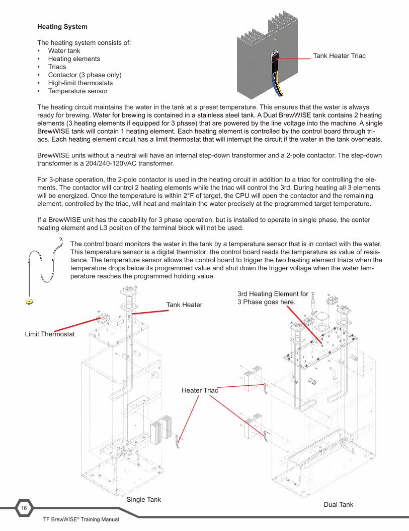
Heating System
The heating system consists of:• Water tank• Heating elements• Triacs• Contactor (3 phase only)• High-limit thermostats• Temperature sensor
The heating circuit maintains the water in the tank at a preset temperature. This ensures that the water is always ready for brewing. Water for brewing is contained in a stainless steel tank. A Dual BrewWISE tank contains 2 heating elements (3 heating elements if equipped for 3 phase) that are powered by the line voltage into the machine. A single BrewWISE tank will contain 1 heating element. Each heating element is controlled by the control board through tri-acs. Each heating element circuit has a limit thermostat that will interrupt the circuit if the water in the tank overheats.
BrewWISE units without a neutral will have an internal step-down transformer and a 2-pole contactor. The step-down transformer is a 204/240-120VAC transformer.
For 3-phase operation, the 2-pole contactor is used in the heating circuit in addition to a triac for controlling the ele-ments. The contactor will control 2 heating elements while the triac will control the 3rd. During heating all 3 elements will be energized. Once the temperature is within 2°F of target, the CPU will open the contactor and the remaining element, controlled by the triac, will heat and maintain the water precisely at the programmed target temperature.
If a BrewWISE unit has the capability for 3 phase operation, but is installed to operate in single phase, the center heating element and L3 position of the terminal block will not be used.
The control board monitors the water in the tank by a temperature sensor that is in contact with the water. This temperature sensor is a digital thermistor; the control board reads the temperature as value of resis-tance. The temperature sensor allows the control board to trigger the two heating element triacs when the temperature drops below its programmed value and shut down the trigger voltage when the water tem-perature reaches the programmed holding value.
Tank Heater Triac
Dual Tank
3rd Heating Element for 3 Phase goes here.
Single Tank
Limit Thermostat
Heater Triac
Tank Heater
Bunn-O-Matic Corporation17
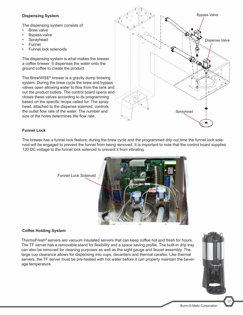
Dispensing System
The dispensing system consists of:• Brew valve• Bypass valve• Sprayhead• Funnel• Funnel lock solenoids
The dispensing system is what makes the brewer a coffee brewer. It dispenses the water onto the ground coffee to create the product.
The BrewWISE® brewer is a gravity dump brewing system. During the brew cycle the brew and bypass valvesopenallowingwatertoflowfromthetankandout the product outlets. The control board opens and closes these valves according to its programming basedonthespecificrecipecalledfor.Thespray-head, attached to the dispense solenoid, controls theoutletflowrateofthewater.Thenumberandsizeoftheholesdeterminestheflowrate.
Funnel Lock
The brewer has a funnel lock feature; during the brew cycle and the programmed drip out time the funnel lock sole-noid will be engaged to prevent the funnel from being removed. It is important to note that the control board supplies 120 DC voltage to the funnel lock solenoid to prevent it from vibrating.
Coffee Holding System
ThermoFresh ® servers are vacuum insulated servers that can keep coffee hot and fresh for hours. TheTFserverhasaremovablestandforflexibilityandaspacesavingprofile.Thebuilt-indriptraycan also be removed for cleaning purposes as well as the sight gauge and faucet assembly. The large cup clearance allows for dispensing into cups, decanters and thermal carafes. Like thermal servers, the TF server must be pre-heated with hot water before it can properly maintain the bever-age temperature.
Funnel Lock Solenoid
Bypass Valve
Dispense Valve
Sprayhead
Unit Objectives
Unit 4 preventive Maintenance
Given a realistic scenario depicting a machine requiring a preventive maintenance, the learner will be able to identify which elements of a component need to be serviced without error.
Given a machine, all the necessary tools and safety equipment, the learner will be able to identify the components that need to be serviced for the PM.
Bunn-O-Matic Corporation19
Preventive Maintenance
In order to maintain proper operation and long service life BUNN recommends performing the preventive mainte-nance every 6 months. Individual customers will vary with some customers choosing not to receive preventive main-tenance.
Tools Required:• 2 Flat blade screwdrivers (#1 - #2)• Phillips screwdriver• 2 adjustable wrenches• Channel lock pliers• Needle nose pliers• Deliming tool BUNN PN: 38227.0000
Prior to servicing the brewer:• Disconnect the electrical supply• Shut off the water supply• Drain the water tank• Remove the front panel• Remove the top panel
PM Steps
IfcustomerhasaBUNNwaterfiltrationsysteminstalledbeforethebrewer,replacethefilterorfiltercartridgeandpurge before installing to the brewer.
Step 1: Rebuild the inlet solenoid □ Shut off the water supply. □ Removebothwiresfromtherefillvalve. □ Disconnect both water lines at the valve. □ Remove the two 1/4”-20 screws securing the valve
to the component mounting bracket.
Step3:Removeandcleanthefilltube □ Usinganadjustablewrenchremovethetubefittingfromthefilltubeontopofthetank □ Gentlypullthefilltubeoutofthetopofthetank □ Wipe any mineral deposits from the exterior of the tube □ Clean any mineral deposits from the bottom of the tube □ Clean any obstructions from the interior of the tube □ Reinstallation is the opposite of removal
Step 4: Rebuild the by-pass solenoids □ Remove the hose clamps that secure the tubing to the valve □ Remove the two nuts that hold the solenoid bracket to the machine □ Gently remove the tubing from the valve body □ Usingaflatbladescrewdriver,removethefourscrewsandseparatethevalveassembly □ Replace plunger, spring, and rubber seat using the rebuild kit. □ Clean any mineral build-up from the valve □ Reassembly is the opposite of disassembly
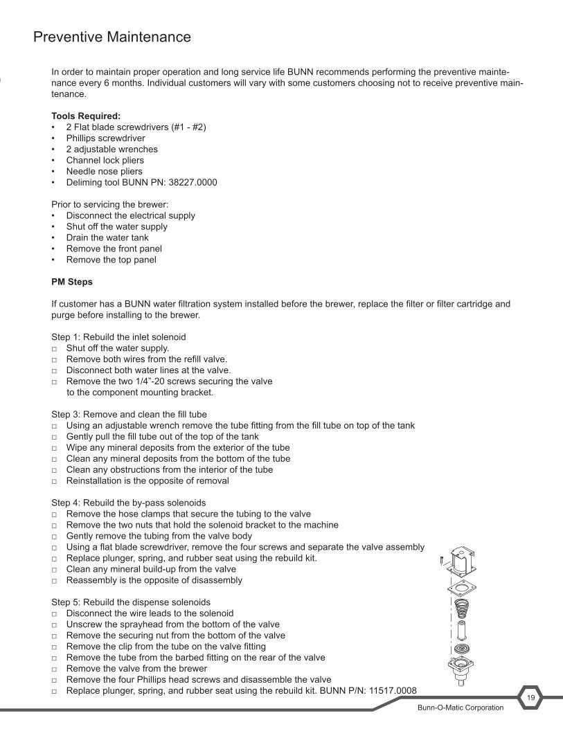
Step 5: Rebuild the dispense solenoids □ Disconnect the wire leads to the solenoid □ Unscrew the sprayhead from the bottom of the valve □ Remove the securing nut from the bottom of the valve □ Removetheclipfromthetubeonthevalvefitting □ Removethetubefromthebarbedfittingontherearofthevalve □ Remove the valve from the brewer □ Remove the four Phillips head screws and disassemble the valve □ Replace plunger, spring, and rubber seat using the rebuild kit. BUNN P/N: 11517.0008
TF BrewWISE® Training Manual
20
□ Clean any mineral build-up from the valve □ Reassembly is the opposite of disassembly
Step6:Cleanthetankfittingsthatsupplywatertothesolenoidvalves(Notedependingontheageofthebrewerthiswill be either a single “T” connector or individual connectors for the dispense and bypass tubes.)
□ Remove the clip from the end of tubes □ Gentlyremovethetubingfromthetankfittings □ Useascrewdrivertoremoveandmineralbuild-upfromthefittings □ Reattach the tubing and clips
Step 7: Remove and clean the temperature sensor □ Gently pull the temperature sensor from the grommet in the top of the tank □ Wipe any mineral build-up from the sensor □ Reinstallation is the opposite of removal
Step8:Removeandcleanthefillprobe □ Gentlypullthefillprobeoutofthegrommet □ Wipe any mineral deposits off of the probe
Step 9: Remove and clean the sprayheads □ Using the pointed end of the deliming tool, remove any mineral build-up from the sprayhead outlet holes
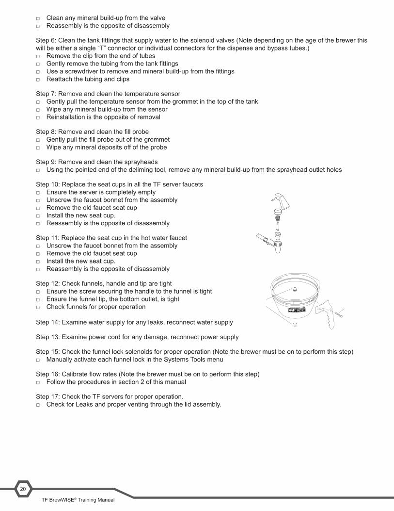
Step 10: Replace the seat cups in all the TF server faucets □ Ensure the server is completely empty □ Unscrew the faucet bonnet from the assembly □ Remove the old faucet seat cup □ Install the new seat cup. □ Reassembly is the opposite of disassembly
Step 11: Replace the seat cup in the hot water faucet □ Unscrew the faucet bonnet from the assembly □ Remove the old faucet seat cup □ Install the new seat cup. □ Reassembly is the opposite of disassembly
Step 12: Check funnels, handle and tip are tight □ Ensure the screw securing the handle to the funnel is tight □ Ensure the funnel tip, the bottom outlet, is tight □ Check funnels for proper operation
Step 14: Examine water supply for any leaks, reconnect water supply
Step 13: Examine power cord for any damage, reconnect power supply
Step 15: Check the funnel lock solenoids for proper operation (Note the brewer must be on to perform this step) □ Manually activate each funnel lock in the Systems Tools menu
Step16:Calibrateflowrates(Notethebrewermustbeontoperformthisstep) □ Follow the procedures in section 2 of this manual
Step 17: Check the TF servers for proper operation. □ Check for Leaks and proper venting through the lid assembly.
S MA R TF U NNE L
Unit Objectives
Unit 5 troubleshooting
Given a realistic scenario depicting a broken machine, the learner will be able to effectively troubleshoot, diagnose, and repair the problem returning the machine to normal operation.
Given a machine displaying an error message, all the necessary tools and safety equipment, the learner will be able to access the software and diagnose the problem.
The learner will be able to access the programming menu. The learner will be able to navigate to the Service Tools menu. The learner will be able use the Service Tools menu to test inputs or outputs.
Given a list of error messages and issues, the learner will be to identify the probable cause of the message or issue.
Given a brewer with a defective component, the learner will be able to test the component to determine the cause of the defect.
TF BrewWISE® Training Manual
22
Troubleshooting and Repair
Service Tools
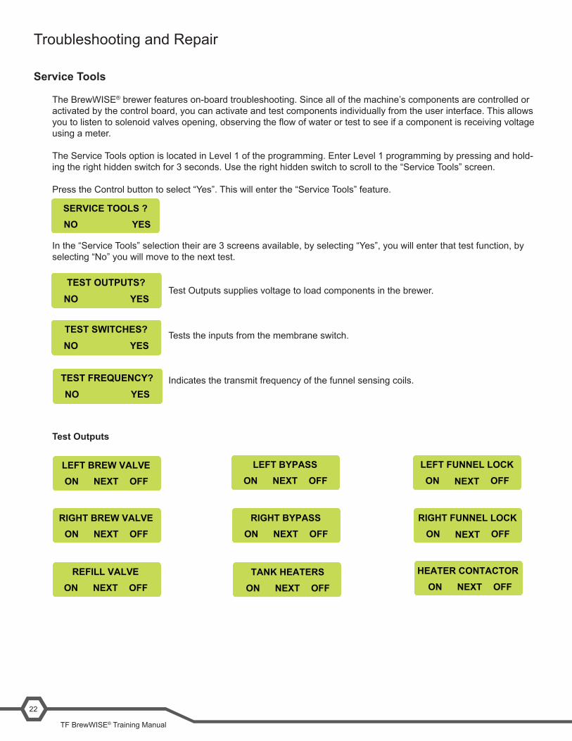
The BrewWISE® brewer features on-board troubleshooting. Since all of the machine’s components are controlled or activated by the control board, you can activate and test components individually from the user interface. This allows youtolistentosolenoidvalvesopening,observingtheflowofwaterortesttoseeifacomponentisreceivingvoltageusing a meter.
The Service Tools option is located in Level 1 of the programming. Enter Level 1 programming by pressing and hold-ing the right hidden switch for 3 seconds. Use the right hidden switch to scroll to the “Service Tools” screen.
Press the Control button to select “Yes”. This will enter the “Service Tools” feature.
In the “Service Tools” selection their are 3 screens available, by selecting “Yes”, you will enter that test function, by selecting “No” you will move to the next test.
Test Outputs supplies voltage to load components in the brewer.
Tests the inputs from the membrane switch.
Indicates the transmit frequency of the funnel sensing coils.
Test Outputs
TEST OUTPUTS?NO YES
TEST SWITCHES?NO YES
TEST FREQUENCY?NO YES
LEFT BREW VALVEON OFFNEXT
LEFT BYPASSON OFFNEXT
LEFT FUNNEL LOCKON OFFNEXT
RIGHT BREW VALVEON OFFNEXT
RIGHT BYPASSON OFFNEXT
RIGHT FUNNEL LOCKON OFFNEXT
REFILL VALVEON OFFNEXT
TANK HEATERSON OFFNEXT
HEATER CONTACTORON OFFNEXT
SERVICE TOOLS ?NO YES
Bunn-O-Matic Corporation23
Test Switches
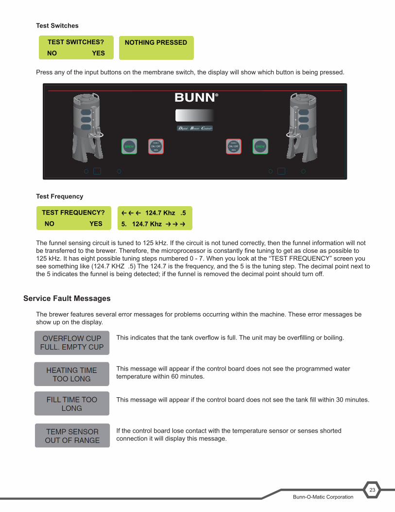
Press any of the input buttons on the membrane switch, the display will show which button is being pressed.
Test Frequency
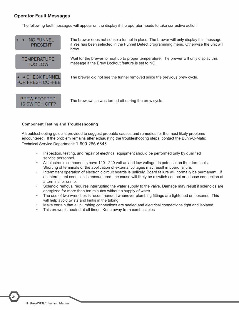
The funnel sensing circuit is tuned to 125 kHz. If the circuit is not tuned correctly, then the funnel information will not betransferredtothebrewer.Therefore,themicroprocessorisconstantlyfinetuningtogetascloseaspossibleto125 kHz. It has eight possible tuning steps numbered 0 - 7. When you look at the “TEST FREQUENCY” screen you see something like (124.7 KHZ .5) The 124.7 is the frequency, and the 5 is the tuning step. The decimal point next to the 5 indicates the funnel is being detected; if the funnel is removed the decimal point should turn off.
Service Fault Messages
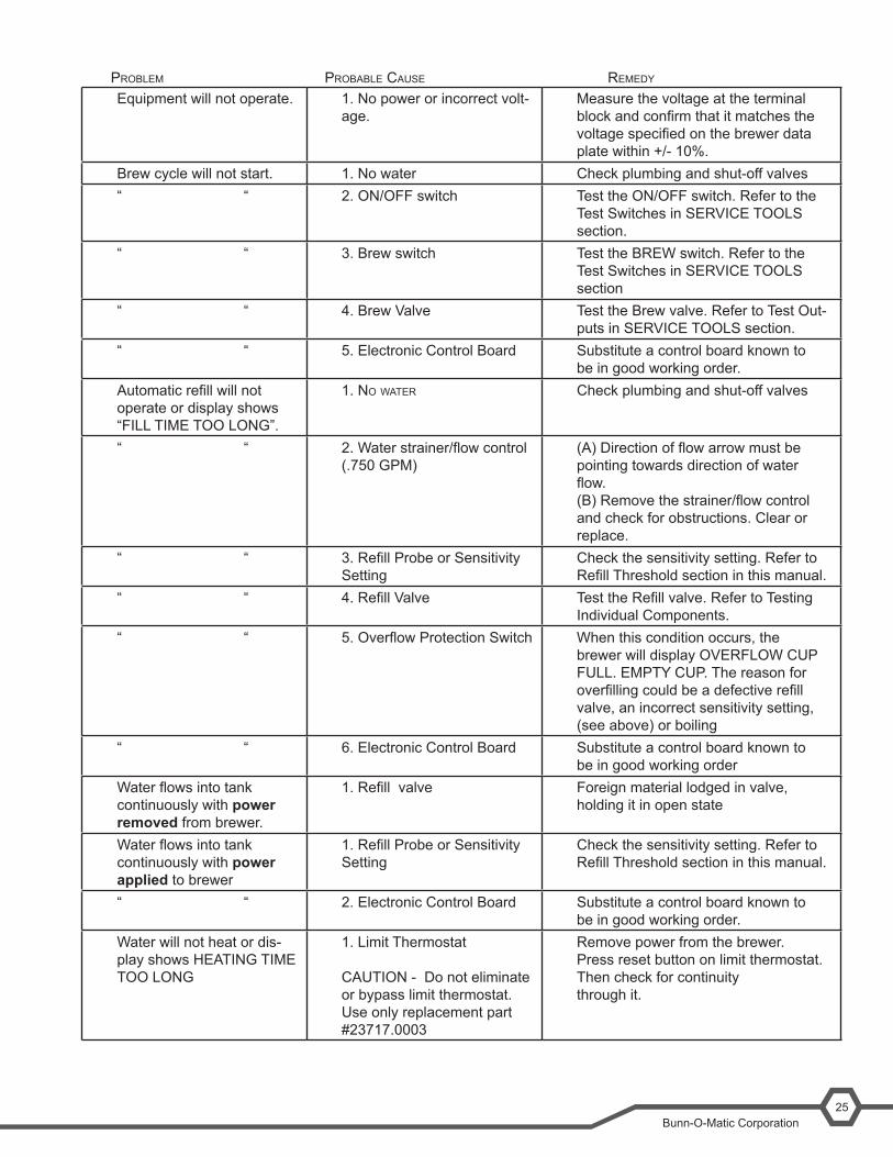
The brewer features several error messages for problems occurring within the machine. These error messages be show up on the display.
Thisindicatesthatthetankoverflowisfull.Theunitmaybeoverfillingorboiling.
This message will appear if the control board does not see the programmed water temperature within 60 minutes.
Thismessagewillappearifthecontrolboarddoesnotseethetankfillwithin30minutes.
If the control board lose contact with the temperature sensor or senses shorted connection it will display this message.
TEST SWITCHES?NO YES
NOTHING PRESSED
TEST FREQUENCY?NO YES
SERVER REMOVEDIN PLACE
124.7 Khz .55. 124.7 Khz
ENABLE
ON / OFFBREW
ENABLE
ON / OFFBREW
TF BrewWISE® Training Manual
24
Operator Fault Messages
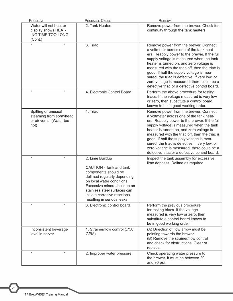
The following fault messages will appear on the display if the operator needs to take corrective action.
The brewer does not sense a funnel in place. The brewer will only display this message if Yes has been selected in the Funnel Detect programming menu. Otherwise the unit will brew.
Wait for the brewer to heat up to proper temperature. The brewer will only display this message if the Brew Lockout feature is set to NO.
The brewer did not see the funnel removed since the previous brew cycle.
The brew switch was turned off during the brew cycle.
Component Testing and Troubleshooting
A troubleshooting guide is provided to suggest probable causes and remedies for the most likely problems encountered. If the problem remains after exhausting the troubleshooting steps, contact the Bunn-O-Matic Technical Service Department: 1-800-286-6345
• Inspection,testing,andrepairofelectricalequipmentshouldbeperformedonlybyqualified service personnel. • Allelectroniccomponentshave120-240voltacandlowvoltagedcpotentialontheirterminals. Shorting of terminals or the application of external voltages may result in board failure. • Intermittentoperationofelectroniccircuitboardsisunlikely.Boardfailurewillnormallybepermanent.If an intermittent condition is encountered, the cause will likely be a switch contact or a loose connection at a terminal or crimp. • Solenoidremovalrequiresinterruptingthewatersupplytothevalve.Damagemayresultifsolenoidsare energized for more than ten minutes without a supply of water. • Theuseoftwowrenchesisrecommendedwheneverplumbingfittingsaretightenedorloosened.This will help avoid twists and kinks in the tubing. • Makecertainthatallplumbingconnectionsaresealedandelectricalconnectionstightandisolated. • Thisbrewerisheatedatalltimes.Keepawayfromcombustibles
Bunn-O-Matic Corporation25
Equipment will not operate. 1. No power or incorrect volt-age.
Measure the voltage at the terminal blockandconfirmthatitmatchesthevoltagespecifiedonthebrewerdataplate within +/- 10%.
Brew cycle will not start. 1. No water Check plumbing and shut-off valves“ “ 2. ON/OFF switch Test the ON/OFF switch. Refer to the
Test Switches in SERVICE TOOLS section.
“ “ 3. Brew switch Test the BREW switch. Refer to the Test Switches in SERVICE TOOLS section
“ “ 4. Brew Valve Test the Brew valve. Refer to Test Out-puts in SERVICE TOOLS section.
“ “ 5. Electronic Control Board Substitute a control board known to be in good working order.
Automaticrefillwillnotoperate or display shows “FILL TIME TOO LONG”.
1. no water Check plumbing and shut-off valves
“ “ 2.Waterstrainer/flowcontrol(.750 GPM)
(A)Directionofflowarrowmustbepointing towards direction of water flow.(B)Removethestrainer/flowcontroland check for obstructions. Clear or replace.
“ “ 3.RefillProbeorSensitivitySetting
Check the sensitivity setting. Refer to RefillThresholdsectioninthismanual.
“ “ 4.RefillValve TesttheRefillvalve.RefertoTestingIndividual Components.
“ “ 5.OverflowProtectionSwitch When this condition occurs, the brewer will display OVERFLOW CUP FULL. EMPTY CUP. The reason for overfillingcouldbeadefectiverefillvalve, an incorrect sensitivity setting, (see above) or boiling
“ “ 6. Electronic Control Board Substitute a control board known to be in good working order
Waterflowsintotankcontinuously with power removed from brewer.
1.Refillvalve Foreign material lodged in valve, holding it in open state
Waterflowsintotankcontinuously with power applied to brewer
1.RefillProbeorSensitivitySetting
Check the sensitivity setting. Refer to RefillThresholdsectioninthismanual.
“ “ 2. Electronic Control Board Substitute a control board known to be in good working order.
Water will not heat or dis-play shows HEATING TIME TOO LONG
1. Limit Thermostat CAUTION - Do not eliminate or bypass limit thermostat. Use only replacement part #23717.0003
Remove power from the brewer. Press reset button on limit thermostat. Then check for continuity through it.
probleM probable cause reMedy
TF BrewWISE® Training Manual
26
Water will not heat or display shows HEAT-ING TIME TOO LONG, (Cont.)
2. Tank Heaters Remove power from the brewer. Check for continuity through the tank heaters.
“ “ 3. Triac Remove power from the brewer. Connect a voltmeter across one of the tank heat-ers. Reapply power to the brewer. If the full supply voltage is measured when the tank heater is turned on, and zero voltage is measured with the triac off, then the triac is good. If half the supply voltage is mea-sured, the triac is defective. If very low, or zero voltage is measured, there could be a defective triac or a defective control board.
“ “ 4. Electronic Control Board Perform the above procedure for testing triacs. If the voltage measured is very low or zero, then substitute a control board known to be in good working order.
Spitting or unusual steaming from sprayhead or air vents. (Water too hot)
1. Triac Remove power from the brewer. Connect a voltmeter across one of the tank heat-ers. Reapply power to the brewer. If the full supply voltage is measured when the tank heater is turned on, and zero voltage is measured with the triac off, then the triac is good. If half the supply voltage is mea-sured, the triac is defective. If very low, or zero voltage is measured, there could be a defective triac or a defective control board.
“ “ 2. Lime Buildup CAUTION - Tank and tank components should be delimed regularly depending on local water conditions. Excessive mineral buildup on stainless steel surfaces can initiate corrosive reactions resulting in serious leaks
Inspect the tank assembly for excessive lime deposits. Delime as required.
“ “ 3. Electronic control board Perform the previous procedure for testing triacs. If the voltage measured is very low or zero, then substitute a control board known to be in good working order
Inconsistent beverage level in server.
1.Strainer/flowcontrol(.750GPM)
(A)Directionofflowarrowmustbepointing towards the brewer.(B)Removethestrainer/flowcontroland check for obstructions. Clear or replace.
“ “ 2. Improper water pressure Check operating water pressure to the brewer. It must be between 20 and 90 psi.
probleM probable cause reMedy

Bunn-O-Matic Corporation27
Inconsistent beverage level in server. (Cont.)
3. brew valve Test the Brew Valve. Turn the valve on for 30 seconds and collect the water dispensed from the sprayhead. Repeat the test several times to con-firmaconsistentvolumeofdispensedwater. If not consistent, check the valve, tubing and sprayhead for lime buildup.
“ “ 4. Bypass Valve If bypass is being used on the inconsistent brewing recipe, test the Bypass Valve. Turn the valve on for 30 seconds and collect the water collected from the bypass opening. Repeat the test several times to con-firmaconsistentvolumeofdispensedwater. If not consistent, check the valve, tubing and bypass opening for lime buildup.
“ “ 5. Lime buildup Inspect for lime buildup that could blockthetank,tankfittings,tubing,valves and sprayhead.
Consistently high or low beverage level in server.
1. Brew Volume adjustment Adjust the brew volume as required to achieve the recommended volume for each brew cycle.
Dripping from sprayhead. 1. Brew Valve Repair or replace leaky valve.Wateroverflowsfilter. 1.Typeofpaperfilters BUNNpaperfiltersshouldbeused
for proper extraction.“ “ 2. No sprayhead Check sprayheadBeverageoverflowsserver.
1. Beverage left in server from previous brew
The brew cycle should be started only with an empty server under the funnel.
“ “ 2. Brew Volume adjustment Adjust the brew volume as required to achieve the recommended volume for each brew cycle.
Weak beverage. 1.Typeofpaperfilters BUNNpaperfiltersshouldbeusedfor proper extraction.
“ “ 2. Coffee Asufficientquantityoffreshdripor regular grind should be used for proper extraction.
“ “ 3. Sprayhead The correct B.O.M. sprayhead should be used to properly wet the bed of ground coffee in the funnel.
“ “ 4. Funnel Loading TheBUNNpaperfiltershouldbecentered in the funnel and the bed of ground coffee leveled by gentle shaking.
probleM probable cause reMedy
TF BrewWISE® Training Manual
28
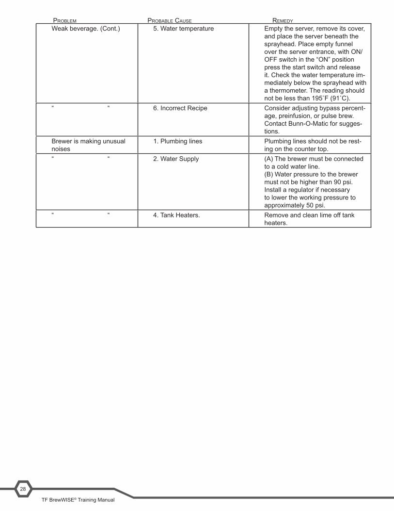
Weak beverage. (Cont.) 5. Water temperature Empty the server, remove its cover, and place the server beneath the sprayhead. Place empty funnel over the server entrance, with ON/OFF switch in the “ON” position press the start switch and release it. Check the water temperature im-mediately below the sprayhead with a thermometer. The reading should notbelessthan195˚F(91˚C).
“ “ 6. Incorrect Recipe Consider adjusting bypass percent-age, preinfusion, or pulse brew. Contact Bunn-O-Matic for sugges-tions.
Brewer is making unusual noises
1. Plumbing lines Plumbing lines should not be rest-ing on the counter top.
“ “ 2. Water Supply (A) The brewer must be connected to a cold water line.(B) Water pressure to the brewer must not be higher than 90 psi. Install a regulator if necessary to lower the working pressure to approximately 50 psi.
“ “ 4. Tank Heaters. Remove and clean lime off tank heaters.
probleM probable cause reMedy
Bunn-O-Matic Corporation29
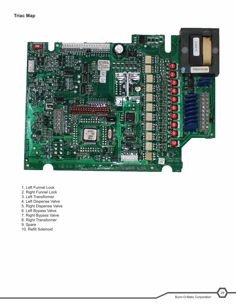
Triac Map
1. Left Funnel Lock2. Right Funnel Lock3. Left Transformer4. Left Dispense Valve5. Right Dispense Valve6. Left Bypass Valve7. Right Bypass Valve8. Right Transformer9. Spare10.RefillSolenoid
1
2
3
4
5
6
7
8
9
10
Unit Objectives
©Bunn-O-Matic Corporation, 2011. All rights reserved. Bunn-O-MaticCorporation-1400StevensonDrive- Springfield,IL62703-Ph:(800)637-8606-Fax(217)529-2177
Additional Resources
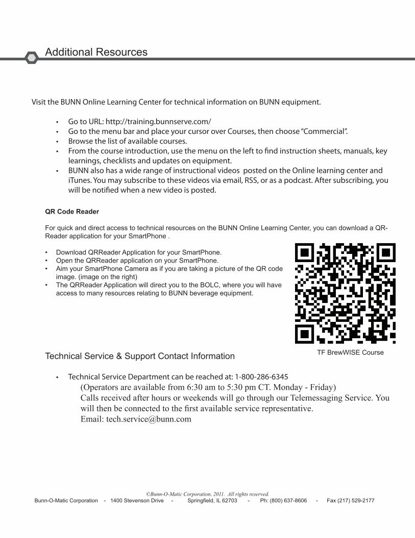
Visit the BUNN Online Learning Center for technical information on BUNN equipment.
• Go to URL: http://training.bunnserve.com/• Go to the menu bar and place your cursor over Courses, then choose “Commercial”.• Browse the list of available courses.• From the course introduction, use the menu on the left to find instruction sheets, manuals, key learnings, checklists and updates on equipment.• BUNN also has a wide range of instructional videos posted on the Online learning center and iTunes. You may subscribe to these videos via email, RSS, or as a podcast. After subscribing, you will be notified when a new video is posted.
QR Code Reader
For quick and direct access to technical resources on the BUNN Online Learning Center, you can download a QR-Reader application for your SmartPhone .
• Download QRReader Application for your SmartPhone.• Open the QRReader application on your SmartPhone.• Aim your SmartPhone Camera as if you are taking a picture of the QR code image. (image on the right)• The QRReader Application will direct you to the BOLC, where you will have access to many resources relating to BUNN beverage equipment.
Technical Service & Support Contact Information
• Technical Service Department can be reached at: 1-800-286-6345 (Operators are available from 6:30 am to 5:30 pm CT. Monday - Friday) Calls received after hours or weekends will go through our Telemessaging Service. You willthenbeconnectedtothefirstavailableservicerepresentative. Email: [email protected]
TF BrewWISE Course
