bulletin 2074a-e panel meters clearline series and … · 12, 13 14 15, 16 17, 18 19 20, 21 22, 23...
TRANSCRIPT

Bulletin 2074A-E

22

3
ContentsContents
Meter Product Line-up
Usage Precautions
Standard Specifications
Key to Numbering System
DC Ammeters
DC Voltmeters
Suppressed Meters (DC Ammeters and Voltmeters)
AC Ammeters (Mean Rectifier Type)
AC Voltmeters (Mean Rectifier Type)
AC Ammeters (Moving Iron Type)
AC Voltmeters (Moving Iron Type)
Frequency Meters
Wattmeters (With External Transducer)
Varmeters (With External Transducer)
Power Factor Meters (With External Transducer)
Dimensions and Panel Mountings
Connection Diagrams
Accessories
4
6
7
8
10
12
14
15
16
17
18
19
20
22
24
26
31
33
4
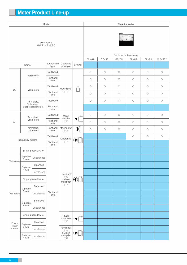
Meter Product Line-up
Model Clearline series
Dimensions(Width Height)
Rectangular type meter
5244 5748 6958 8269 10285 122102
Name Suspension type
Operating principle Symbol
DC
Ammeters
Taut band
Moving coil type
Pivot and jewel
Voltmeters
Taut band
Pivot and jewel
Ammeters, Voltmeters,
Suppressed meters
Taut band
Pivot and jewel
AC
Ammeters, Voltmeters
Taut band Mean rectifier
type
Pivot and jewel
Ammeters, Voltmeters
Pivot and jewel
Moving iron type
Frequency meters
Taut bandDifferential
type
Pivot and jewel
Wattmeters
Single phase 2-wire
Pivot and jewel
Feedback time
division multiplier
type
3-phase 3-wire Unbalanced
3-phase 4-wire
Balanced
Unbalanced
Varmeters
Single phase 2-wire
3-phase 3-wire
Balanced
Unbalanced
3-phase 4-wire
Balanced
Unbalanced
Powerfactormeters
Single phase 2-wire Phase detection
type3-phase 3-wire
Balanced
UnbalancedFeedback
time division
multiplier type
3-phase 4-wire Unbalanced
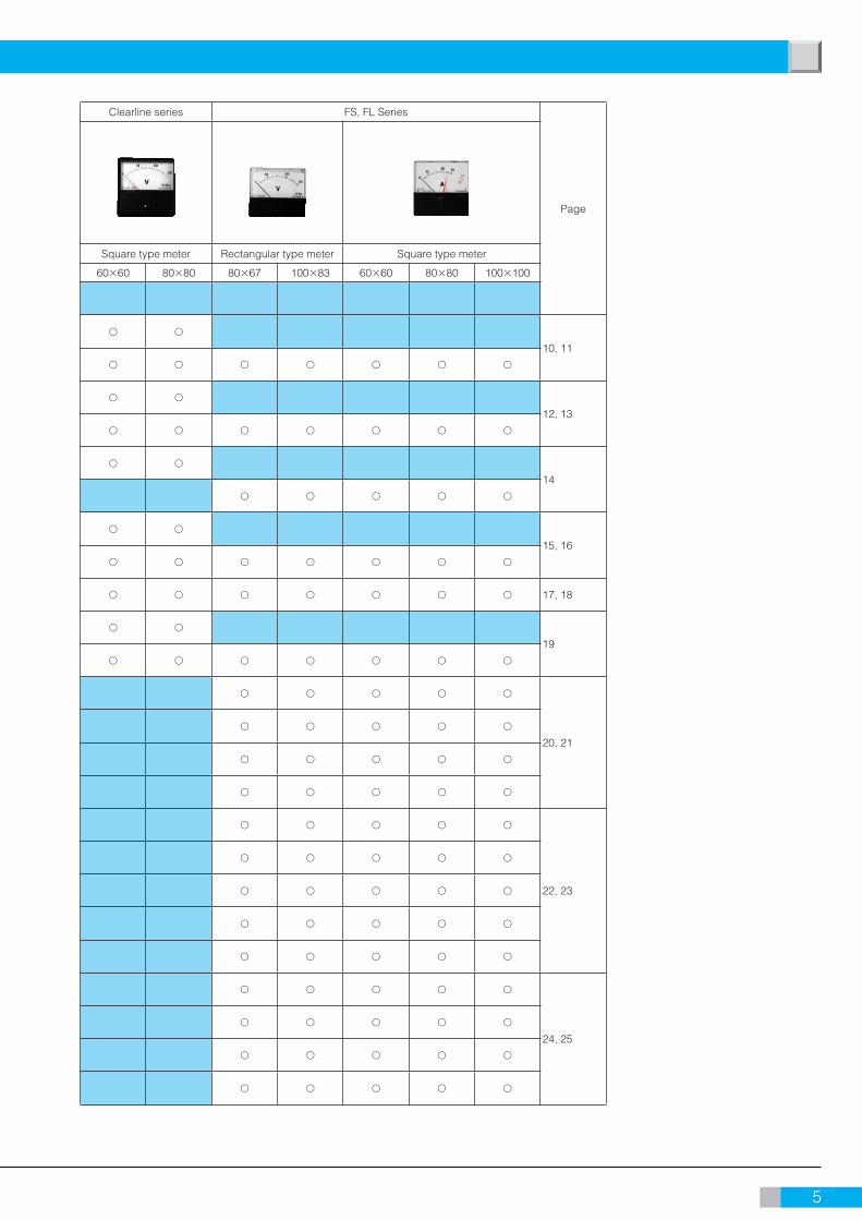
5
Clearline series FS, FL Series
Page
Square type meter Rectangular type meter Square type meter
6060 8080 8067 10083 6060 8080 100100
10, 11
12, 13
14
15, 16
17, 18
19
20, 21
22, 23
24, 25

6
Usage Precautions
Safety instructions for Panel meters
WarningIndicates usage precautions that must be read to ensure the safety of users and the equipment.
1. Usage environment and conditionsDo not use YOKOGAWA panel meters in locations such as the following:• Locations where the ambient temperature is outside the
range of 0 to 40°C• Locations where relative humidity is outside the range of
25 to 80%• Locations subject to vibrations or shock impact• Locations subject to rain, dripping water, or direct
sunlight• Locations exposed to large amounts of dust, salt, soot,
or corrosive gases (sulfurous acid gas, ammonia gas, hydrogen sulfi de gas,
or other gases that corrode metals or plastics)• Locations subject to strong external noise or
electromagnetic waves• Locations subject to large amounts of static electricity• Locations subject to large amounts of high frequencies
and waveform distortion (e.g., from inverters or thyristor circuits)
2. Mounting methodAdhere to safety rules at the construction, maintenance and inspection• Check the appearance of the packing box and panel
meters and confi rm that there is no damage.• Use the metal for mounting panel and ground it.• If necessary, combine with washers and others and
fasten, in the case of panel boards and switchboards are thin.
• Fasten nuts of mounting on boards to the proper torque for the size of screw being used with the proper tool.
Recommended tightening torque : M3 screws - 0.6N·m M4 screws - 1.2N·m M5 screws - 2.0N·m 3. WiringAdhere to the following rules when connecting the wires:• When connecting an instrument with accessories, fi rst
make sure none of the wires are live.• When connecting main power directly, install and use the
proper fuse.• The connector terminals on the wires should be
appropriate for the electricity load and terminal size.• Connect the wires properly as illustrated in the wiring
diagrams of catalogs or on product labels.• Attach to terminal cover for safety.• Fasten terminal screws to the proper torque for the size
of screw being used with the proper tool. Recommended tightening torque : M3 screws - 0.6N·m M4 screws - 1.2N·m M5 screws - 2.0N·m• Instruments that are combined with current transformers
(CT) should be properly connected to the secondary side of the CT. Improper connection may result in a CT failure, burned components, or a fi re. When the
secondary side of a CT is disconnected, especially while the primary side is powered, the secondary side terminal will carry a high voltage which could result in electrical shock. Therefore, the secondary side should be short-circuited before the instrument is disconnected.
4. Usage precautions• Use the instruments at the front of mounting panel. • Never touch the inside of mounting panel.• Use the instrument within the rated specifi cations.
Failure to do so can cause the equipment to malfunction or result in a failure.
• While the power is on, do not touch any terminals or open the cover or case.
• The current transformer emits heat while powered, so do not touch it.
5. What to do if the equipment functions abnormally or fails
• If you notice abnormal heating, or a strange odor, noises, or smoking or if the equipment seems to have failed, immediately take steps such as cutting off the input. Next, contact your YOKOGAWA sales offi ce.
6. Maintenance and inspection To ensure that your instrument operates properly,
perform the following checks on a regular basis:• Check for damage to the instrument or accessories due
to heating or other factors.• Check for loose attachments or screws (always turn off
the power before doing this to ensure safety).• The instrument covers have been coated with an
antistatic agent to block static electricity. Gently wipe dirt off the cover surfaces with a soft, dry cloth. Do not use a wet cloth as this will reduce the effects of the antistatic coating. Do not allow cloths made from synthetic materials to contact the cover for an extended period of time, and do not use benzene, paint thinner, or similar substances. Doing so may cause the cover to become deformed, discolor it, or cause cracking.
• If the indicator reading becomes unstable due to static electricity, coat the front and back of the cover with a commercially available antistatic agent.
• Instrument service life will vary according to usage conditions. In general, however, we recommend replacing the instrument after about 10 years of use.
7. Disposal of product• Panel meters do not contain batteries.• Dispose of panel meters as general industrial waste.
8. For aluminum electrolytic capacitors Frequency meters use aluminum electrolytic capacitors.
The lifetime of aluminum electrolytic capacitors are around 10 years when ambient temperatures are 23°C. If aluminum electrolytic capacitors run down and meters are damaged, replace new frequency meters.

7
Analog panel meters have been widely used in various industries particularly at electrical equipmentand machineries for its simplicity and high reliability of the products for the measurements of electricalquantities of current, voltage and power.Meters play an important role as a man-machine interface. For an appropriate use of meters, it is important to consider several points such as a place of use, products design, size of meters, product performance, cost and manufacture's reliability, Yokogawa's Clearline and FS, FL series offeryou with the full range of products to satisfy your requirements.
ItemSpecifications
Clearline series FS, FL Series
Standard JIS C1102: 2007
Suspension type Taut band or Pivot and jewel Pivot and jewel
Pointer type
Knife edge type (red color): For all
Bar type (black color)Lance type (black color): For 20 4A to 206A
Bar type (black color): For 201 to 203
Color of front cover
Munsell N1.5 (black)
Munsell N1.5 (black)Munsell N7.5BG4/1.5 (blue-green)
Semitransparency (for 2093A, 2094A)
Front cover dimensions(Width Height)
Model No. Dimensions Model No. Dimensions
2071, 2081 5244 mm FL80 80×67 mm
2072, 2082 5748 mm FL10 100×83 mm
2073, 2083 6958 mm FS60 60×60 mm
2074A, 2084A 8269 mm FS80 80×80 mm
2075A, 2085A 10285 mm FS10 100×100 mm
2076A, 2086A 122102 mm
2093A 6060 mm
2094A 8080 mm
Scale length
Model No. Scale length Model No. Scale length
2071, 2081 29 mm FL80 62 mm
2072, 2082 34 mm FL10 79 mm
2073, 2083 47.5 mm FS60 47.5 mm
2074A, 2084A 62 mm (for Knife edge type: 63.5 mm) FS80 62 mm
2075A, 2085A 79 mm (for Knife edge type: 80.5 mm) FS10 79 mm
2076A, 2086A 101 mm (for Knife edge type:103 mm)
2093A 47.5 mm
2094A 62 mm(for Knife edge type: 63.5 mm)
Full scale deflection angle 90°
Meter mounting position Vertical ()*1
Insulation resistanceBetween electrical circuit and the case: 500 V DC/More than 10 MΩBetween current circuit and voltage circuit: 500 V DC/More than 5 MΩ (For Watt, Var and Power factor meters)
Dielectric strengthBetween electrical circuit and the case: 2210 V AC for 5seconds, 3320V AC for Moving iron type
Between current circuit and Voltage circuit: 2000V AC for 5 seconds (For Watt, Var and Power factor meters)
Operating temperature range 0 to 40°C
Operating humidity range 25 to 80%RH
Storage temperature range 10 to 50°C
Storage humidity range 25 to 80%RH
Safety Requirements
Structural requirements are in accordance with JIS C 1010 for safety of voltage test, insulation and other.Reinforced insulation, between electrical circuit and caseIndoors, Altitudes up to 2000m, Pollution degree 2Measurement category III (Measurement category is not applied for non- JIS products.)Maximum working voltage: 300V for DC meters, AC meters(Mean rectifier type), Wattmeters, Varmeters, Power factor
meters and Frequency meters 600V for AC meters(Moving iron type)
Case materialBase material: ABS resin (Nonflammable)
Front cover material: Acrylic resin
*1 Specify horizontal or angle for inclined mounting as shown on the following fi gure (ex. 75°), when meter mounting position is not vertical.
75˚Front side
Standard Specifi cations
8
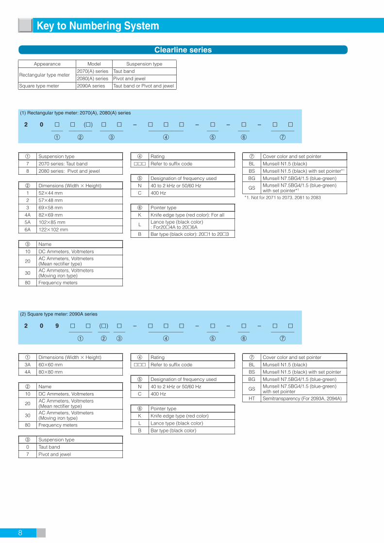
Appearance Model Suspension type
Rectangular type meter2070(A) series Taut band
2080(A) series Pivot and jewel
Square type meter 2090A series Taut band or Pivot and jewel
1 Suspension type
7 2070 series: Taut band
8 2080 series: Pivot and jewel
2 Dimensions (Width Height)
1 5244 mm
2 5748 mm
3 6958 mm
4A 8269 mm
5A 10285 mm
6A 122102 mm
3 Name
10 DC Ammeters, Voltmeters
20 AC Ammeters, Voltmeters(Mean rectifier type)
30 AC Ammeters, Voltmeters(Moving iron type)
80 Frequency meters
1 Dimensions (Width Height)
3A 6060 mm
4A 8080 mm
2 Name
10 DC Ammeters, Voltmeters
20 AC Ammeters, Voltmeters(Mean rectifier type)
30 AC Ammeters, Voltmeters(Moving iron type)
80 Frequency meters
3 Suspension type
0 Taut band
7 Pivot and jewel
(1) Rectangular type meter: 2070(A), 2080(A) series
2 0 () – – – – —— ———— ———— —————— —— —— ————1 2 3 4 5 6 7
Clearline series
4 Rating
Refer to suffix code
5 Designation of frequency used
N 40 to 2 kHz or 50/60 Hz
C 400 Hz
6 Pointer type
K Knife edge type (red color): For all
L Lance type (black color): For204A to 206A
B Bar type (black color): 201 to 203
7 Cover color and set pointer
BL Munsell N1.5 (black)
BS Munsell N1.5 (black) with set pointer*1
BG Munsell N7.5BG4/1.5 (blue-green)
GS Munsell N7.5BG4/1.5 (blue-green) with set pointer*1
*1. Not for 2071 to 2073, 2081 to 2083
7 Cover color and set pointer
BL Munsell N1.5 (black)
BS Munsell N1.5 (black) with set pointer
BG Munsell N7.5BG4/1.5 (blue-green)
GS Munsell N7.5BG4/1.5 (blue-green) with set pointer
HT Semitransparency (For 2093A, 2094A)
Key to Numbering System
(2) Square type meter: 2090A series
2 0 9 () – – – – ———— —— —— —————— —— —— ————
1 2 3 4 5 6 7
4 Rating
Refer to suffix code
5 Designation of frequency used
N 40 to 2 kHz or 50/60 Hz
C 400 Hz
6 Pointer type
K Knife edge type (red color)
L Lance type (black color)
B Bar type (black color)

9
Appearance 1 Dimensions (Width Height)
Rectangular type meter
FS60 6060 mm
FS80 8080 mm
FS10 100100 mm
Square type meter
FL80 8067 mm
FL10 10083 mm
Notes: Suspension type is pivot and jewel for all.
2 Name
DA DC Ammeters
DV DC Voltmeters
RA AC Ammeters (Mean rectifier type)
RV AC Voltmeters (Mean rectifier type)
SA AC Ammeters (Moving iron type)
SV AC Voltmeters (Moving iron type)
W1
Wattmeters*
Single phase 2-wire
W4 3-phase 4-wire Balanced
W5 3-phase 3-wire Unbalanced
W6 3-phase 4-wire Unbalanced
Q1
Varmeters*
Single phase 2-wire
Q3 3-phase 3-wire Balanced
Q4 3-phase 4-wire Balanced
Q5 3-phase 3-wire Unbalanced
Q6 3-phase 4-wire Unbalanced
P1Power factor meters*
Single phase 2-wire
P3 3-phase 3-wire Balanced
P5 3-phase 3-wire Unbalanced
P6 3-phase 4-wire Unbalanced
FR Frequency meters
* With external transducer box.
3 Rating
Refer to suffix code
4 Designation of frequency used
N 40 to 2 kHz or 50/60 Hz
A 50 Hz
B 60 Hz
C 400 Hz
5 Pointer type
B Bar type (black color)
6 Cover color and set pointer
BL Munsell N1.5 (black)
BS Munsell N1.5 (black) with set pointer
FS, FL Series
– – – B – —————————— ———— ——————— —— —— ————
1 2 3 4 5 6
10
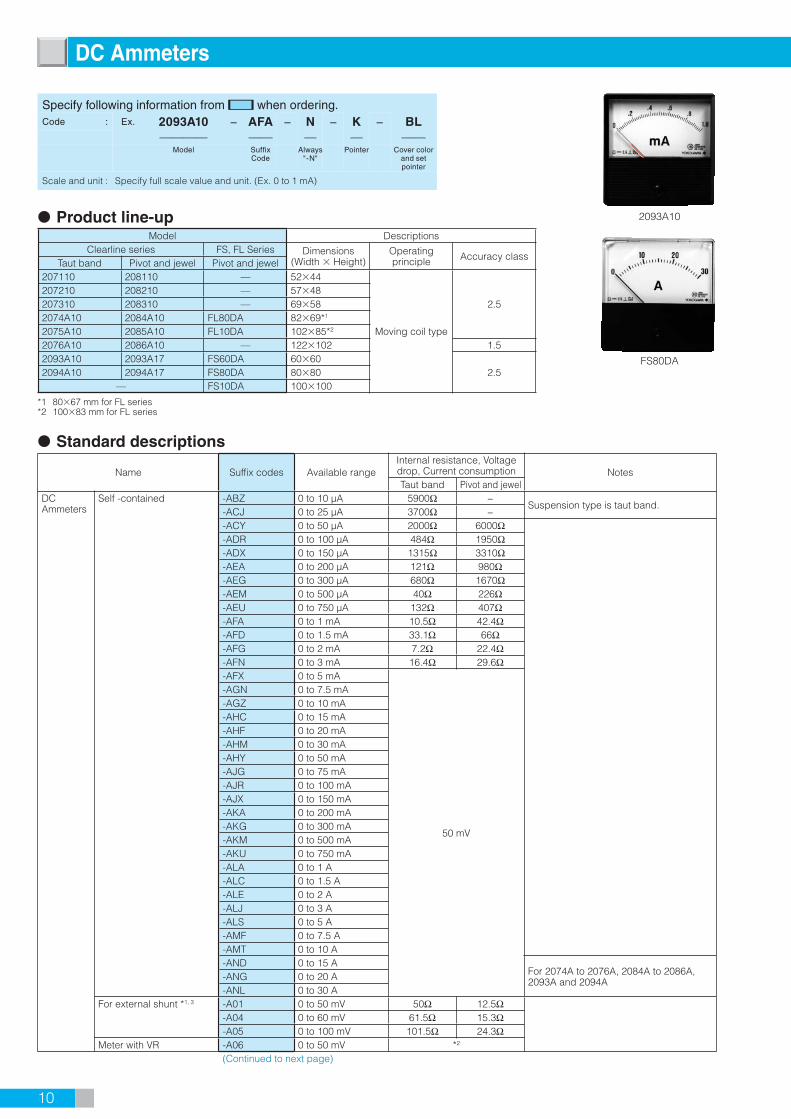
Standard descriptions
Name Suffix codes Available rangeInternal resistance, Voltage drop, Current consumption NotesTaut band Pivot and jewel
DC Ammeters
Self -contained -ABZ 0 to 10 µA 5900Ω −Suspension type is taut band.
-ACJ 0 to 25 µA 3700Ω −-ACY 0 to 50 µA 2000Ω 6000Ω-ADR 0 to 100 µA 484Ω 1950Ω-ADX 0 to 150 µA 1315Ω 3310Ω-AEA 0 to 200 µA 121Ω 980Ω-AEG 0 to 300 µA 680Ω 1670Ω-AEM 0 to 500 µA 40Ω 226Ω-AEU 0 to 750 µA 132Ω 407Ω-AFA 0 to 1 mA 10.5Ω 42.4Ω-AFD 0 to 1.5 mA 33.1Ω 66Ω-AFG 0 to 2 mA 7.2Ω 22.4Ω-AFN 0 to 3 mA 16.4Ω 29.6Ω-AFX 0 to 5 mA
50 mV
-AGN 0 to 7.5 mA-AGZ 0 to 10 mA-AHC 0 to 15 mA-AHF 0 to 20 mA-AHM 0 to 30 mA-AHY 0 to 50 mA-AJG 0 to 75 mA-AJR 0 to 100 mA-AJX 0 to 150 mA-AKA 0 to 200 mA-AKG 0 to 300 mA-AKM 0 to 500 mA-AKU 0 to 750 mA-ALA 0 to 1 A-ALC 0 to 1.5 A-ALE 0 to 2 A-ALJ 0 to 3 A-ALS 0 to 5 A-AMF 0 to 7.5 A-AMT 0 to 10 A-AND 0 to 15 A
For 2074A to 2076A, 2084A to 2086A, 2093A and 2094A-ANG 0 to 20 A
-ANL 0 to 30 AFor external shunt *1, 3 -A01 0 to 50 mV 50Ω 12.5Ω
-A04 0 to 60 mV 61.5Ω 15.3Ω-A05 0 to 100 mV 101.5Ω 24.3Ω
Meter with VR -A06 0 to 50 mV *2
(Continued to next page)
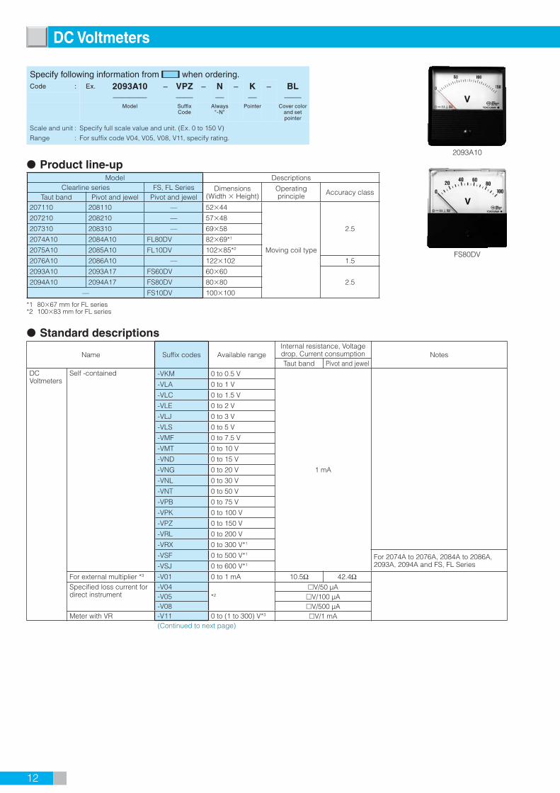
2093A10
FS80DA
DC Ammeters
Product line-upModel Descriptions
Clearline series FS, FL Series Dimensions(Width Height)
Operating principle Accuracy class
Taut band Pivot and jewel Pivot and jewel207110 208110 — 5244
Moving coil type
2.5207210 208210 — 5748207310 208310 — 69582074A10 2084A10 FL80DA 8269*1
2075A10 2085A10 FL10DA 10285*2
2076A10 2086A10 — 122102 1.52093A10 2093A17 FS60DA 6060
2.52094A10 2094A17 FS80DA 8080— FS10DA 100100
*1 8067 mm for FL series*2 10083 mm for FL series
Specify following information from when ordering.Code : Ex. 2093A10 − AFA − N − K − BL
———— —— — — ——Model Suffix
CodeAlways
"-N"Pointer Cover color
and set pointer
Scale and unit : Specify full scale value and unit. (Ex. 0 to 1 mA)

11
Standard descriptions
Name Suffix codes Available rangeInternal resistance, Voltage drop, Current consumption NotesTaut band Pivot and jewel
DC Ammeters
Zero-center meter -DAX ±5 µA 5900Ω — Suspension type is taut band.-DCJ ±25 µA 2000Ω 6000Ω-DCY ±50 µA 484Ω 1950Ω-DDH ±75 µA 1315Ω 3310Ω-DDR ±100 µA 121Ω 980Ω-DDX ±150 µA 680Ω 1670Ω-DED ±250 µA 40Ω 226Ω-DEM ±500 µA 10.5Ω 42.4Ω-DEU ±750 µA 33.1Ω 66Ω-DFA ±1 mA 7.2Ω 22.4Ω-DFD ±1.5 mA 16.4Ω 29.6Ω-DFK ±2.5 mA
±25 mV
-DFX ±5 mA-DGN ±7.5 mA-DGZ ±10 mA-DHC ±15 mA-DHJ ±25 mA-DHY ±50 mA-DJG ±75 mA-DJR ±100 mA-DJX ±150 mA-DKD ±250 mA-DKM ±500 mA-DKU ±750 mA-DLA ±1 A-DLC ±1.5 A-DLG ±2.5 A-DLS ±5 A-DMF ±7.5 A
For 2074A to 2076A, 2084A to 2086A, 2093A and 2094A-DMT ±10 A
-DND ±15 AFor external shunt *1, 3 -D01 ±50 mV 101.5Ω 24.3Ω
Designation of frequency used -N Always "-N"
Pointer type
-K Knife edge type (red color) For Clearline series
-L Lance type (black color) For 2074A to 2076A, 2084A to 2086A, 2093A, 2094A
-B Bar type (black color) For 2071 to 2073, 2081 to 2083, 2093A, 2094A and FS, FL Series
Cover type Standard type -BL Munsell N1.5 (black)-BG Munsell N7.5BG4/1.5 (blue-green) For Clearline series-HT Semitransparency For 2093A, 2094A
With set pointer (red) -BS Munsell N1.5 (black) For 2074A to 2076A, 2084A to 2086A, 2093A, 2094A and FS, FL Series
-GS Munsell N7.5BG4/1.5 (blue-green) For 2074A to 2076A, 2084A to 2086A, 2093A, 2094A
Notes: *1 The 50 mV, 60 mV, 100 mV and ±50 mV instruments are not provided with any shunt lead. Use any lead wire of which resistance is less than 0.05Ω in total. External shunts are not supplied. *2 For 50 mV instrument with VR, current consumption is 1 mA and shunt lead's resistance compensates 2 to 0Ω. *3 An external shunt is not supplied.
12
Standard descriptions
Name Suffix codes Available rangeInternal resistance, Voltage drop, Current consumption NotesTaut band Pivot and jewel
DC Voltmeters
Self -contained -VKM 0 to 0.5 V
1 mA
-VLA 0 to 1 V
-VLC 0 to 1.5 V
-VLE 0 to 2 V
-VLJ 0 to 3 V
-VLS 0 to 5 V
-VMF 0 to 7.5 V
-VMT 0 to 10 V
-VND 0 to 15 V
-VNG 0 to 20 V
-VNL 0 to 30 V
-VNT 0 to 50 V
-VPB 0 to 75 V
-VPK 0 to 100 V
-VPZ 0 to 150 V
-VRL 0 to 200 V
-VRX 0 to 300 V*1
-VSF 0 to 500 V*1 For 2074A to 2076A, 2084A to 2086A, 2093A, 2094A and FS, FL Series-VSJ 0 to 600 V*1
For external multiplier *3 -V01 0 to 1 mA 10.5Ω 42.4ΩSpecified loss current for direct instrument
-V04*2
V/50 µA-V05 V/100 µA-V08 V/500 µA
Meter with VR -V11 0 to (1 to 300) V*3 V/1 mA(Continued to next page)
2093A10
FS80DV
DC Voltmeters
Product line-upModel Descriptions
Clearline series FS, FL Series Dimensions(Width Height)
Operating principle Accuracy class
Taut band Pivot and jewel Pivot and jewel207110 208110 — 5244
Moving coil type
2.5
207210 208210 — 5748
207310 208310 — 6958
2074A10 2084A10 FL80DV 8269*1
2075A10 2085A10 FL10DV 10285*2
2076A10 2086A10 — 122102 1.5
2093A10 2093A17 FS60DV 6060
2.52094A10 2094A17 FS80DV 8080
— FS10DV 100100
*1 8067 mm for FL series*2 10083 mm for FL series
Specify following information from when ordering.Code : Ex. 2093A10 − VPZ − N − K − BL
———— —— — — ——Model Suffix
CodeAlways
"-N"Pointer Cover color
and set pointer
Scale and unit
Range
:
:
Specify full scale value and unit. (Ex. 0 to 150 V)
For suffix code V04, V05, V08, V11, specify rating.

13
Standard descriptions
Name Suffix codes Available rangeInternal resistance, Volatage drop, Current consumption NotesTaut band Pivot and jewel
DC Voltmeters
Zero-center meter -EKD ±0.25 V
0.5 mA
-EKM ±0.5 V
-EKU ±0.75 V
-ELA ±1 V
-ELC ±1.5 V
-ELG ±2.5 V
-ELS ±5 V
-EMF ±7.5 V
-EMT ±10 V
-END ±15 V
-ENJ ±25 V
-ENT ±50 V
-EPB ±75 V
-EPK ±100 V
-EPZ ±150 V
-ERS ±250 V For 2074A to 2076A, 2084A to 2086A, 2093A, 2094A and FS, FL Series
-ERX ±300 V
For external multiplier *3 -E01 ±1 mA*1 7.2Ω 22.4ΩDesignation of frequency used -N Always "-N"Pointer type -K Knife edge type (red color) For Clearline series
-L Lance type (black color) For 2074A to 2076A, 2084A to 2086A, 2093A, 2094A
-B Bar type (black color) For 2071 to 2073, 2081 to 2083, 2093A, 2094A and FS, FL Series
Cover type Standard type -BL Munsell N1.5 (black)
-BG Munsell N7.5BG4/1.5 (blue-green) For Clearline series
-HT Semitransparency For 2093A, 2094AWith set pointer (red) -BS Munsell N1.5 (black) For 2074A to 2076A, 2084A to 2086A,
2093A, 2094A and FS, FL Series
-GS Munsell N7.5BG4/1.5 (blue-green) For 2074A to 2076A, 2084A to 2086A, 2093A, 2094A
Notes: *1 For non-JIS products. *2 Specify from the above-mentioned rating between 0.5 V and 300 V. *3 ±20% Variable *4 An external multiplier is not supplied.

14
Product line-upModel Descriptions
Clearline series FS, FL Series Dimensions(Width Height)
Operating principle Accuracy class
Taut band Pivot and jewel
207110 — 5244
Moving coil type
2.5
207210 — 5748
207310 — 6958
2074A10 FL80DA, FL80DV *1 8269 *1
2075A10 FL10DA, FL10DV *1 10285 *2
2076A10 — 122102 1.5
2093A10 FS60DA, FS60DV *1 6060
2.52094A10 FS80DA, FS80DV *1 8080
— FS10DA, FS10DV *1 100100
*1 "DA" is ammeters, "DV" is voltmeters.*2 8067 mm for FL series*3 10083 mm for FL series
Standard descriptions
Name Suffix codes Available rangeInternal resistance, Voltage drop, Current consumption NotesTaut band Pivot and jewel
Suppressed meters
DC Ammeters -AHE 4 to 20 mA 3.1Ω 3Ω-AHX 10 to 50 mA 1.2Ω 2.4Ω-A11 0.2 to 1 mA 125Ω —
For Clearline series-A12 1 to 5 mA 12.2Ω —
-A13 2 to 10 mA 6.2Ω —
DC Voltmeters -VLR 1 to 5 V 3.9kΩDesignation of frequency used -N Always "-N"Pointer type - K Knife edge type(red color) For Clearline series
- L Lance type(black color) For 2074A to 2076A, 2084A to 2086A, 2093A, 2094A
- B Bar type(black color) For 2071 to 2073, 2081 to 2083, 2093A, 2094A and FS,FL Series
Cover type Standard type -BL Munsell N1.5(black)
-BG Munsell N7.5BG4/1.5 (blue-green) For Clearline series
-HT Semitransparency For 2093A, 2094AWith set pointer (red) - BS Munsell N1.5(black) For 2074A to 2076A, 2084A to 2086A,
2093A, 2094A and FS,FL Series
-GS Munsell N7.5BG4/1.5 (blue-green) For 2074A to 2076A, 2084A to 2086A, 2093A, 2094A
2093A10
FS80DA
Suppressed Meters (DC Ammeters and Voltmeters)
Specify following information from when ordering.Code : Ex. 2093A10 − VLR − N − K − BL
———— —— — — ——Model Suffix
CodeAlways
"-N"Pointer Cover color
and set pointer
Scale and unit : Specify full scale value and unit. (Ex. 0 to 100%)

15
Product line-upModel Descriptions
Clearline series FS, FL Series Dimensions(Width Height)
Operating principle Accuracy class
Taut band Pivot and jewel Pivot and jewel
207120 208120 — 5244
Mean rectifier type 2.5
207220 208220 — 5748
207320 208320 — 6958
2074A20 2084A20 FL80RA 8269 *1
2075A20 2085A20 FL10RA 10285 *2
2076A20 2086A20 — 122102
2093A20 2093A27 FS60RA 6060
2094A20 2094A27 FS80RA 8080
— FS10RA 100100
*1 8067 mm for FL series*2 10083 mm for FL series
Standard descriptions
Name Suffix codes Available rangeInternal resistance
NotesTaut band Pivot and jewel
AC Ammeters
Self -contained -AEA 0 to 200µA 2536Ω 3380Ω-AEM 0 to 500µA 1286Ω 1470Ω-AFA 0 to 1 mA 774Ω 797Ω-AFG 0 to 2 mA 508Ω 507Ω-AFX 0 to 5 mA 285Ω 292Ω-AGZ 0 to 10 mA 207Ω 181Ω-AHF 0 to 20 mA 118Ω 94Ω
Designation of frequency used -N Always "-N" (40 Hz to 2 kHz)Pointer type -K Knife edge type (red color) For Clearline series
- L Lance type (black color) For 2074A to 2076A, 2084A to 2086A, 2093A, 2094A
-B Bar type (black color) For 2071 to 2073, 2081 to 2083, 2093A, 2094A and FS,FL Series
Cover type Standard type -BL Munsell N1.5 (black)
-BG Munsell N7.5BG4/1.5 (blue-green) For Clearline series
-HT Semitransparency For 2093A, 2094AWith set pointer (red) -BS Munsell N1.5 (black) For 2074A to 2076A, 2084A to 2086A,
2093A, 2094A and FS,FL Series
-GS Munsell N7.5BG4/1.5 (blue-green) For 2074A to 2076A, 2084A to 2086A, 2093A, 2094A
*1 An external CT is not supplied. If necessary, externally connect a CT (224800).
2093A20
FS80RA
AC Ammeters (Mean Rectifi er Type)
Specify following information from when ordering.Code : Ex. 2093A20 − AEA − N − K − BL
———— —— — — ——Model Suffix
CodeAlways
"-N"Pointer Cover color
and set pointer
Scale and unit
CT ratio
:
:
Specify full scale value and unit. (Ex. 0 to 200µA)
If necessary, specify CT ratio.

16
Standard descriptions
Name Suffix codes Available rangeInternal resistance
NotesTaut band Pivot and jewel
AC Voltmeters
Self -contained -VLJ 0 to 3 V 3kΩ 2.8kΩ
For non-JIS products
-VLS 0 to 5 V 5kΩ 4.7kΩ-VMT 0 to 10 V 9.8kΩ 9.6kΩ-VND 0 to 15 V 15kΩ 14.8kΩ-VNL 0 to 30 V 30kΩ 29.8kΩ-VNT 0 to 50 V 48.5kΩ-VPB 0 to 75 V 75Ω-VPK 0 to 100 V 101.6kΩ-VPZ 0 to 150 V 151.6kΩ-VRL 0 to 200 V 201.6kΩ-VRX 0 to 300 V 301.6kΩ
For external multiplier *3 -V01 0 to 1 mA 774Ω 797kΩFor external VT *3 -V12 0 to 150 V 151.6kΩSpecified loss current for direct instrument
-V06*1
V/200 µA
-V08 V/500 µAMeter with VR -V11 0 to 3 V, 0 to 5 V,
0 to (10 to 300 V) *2 V/1 mA
Designation of frequency used -N Always "-N" (40 Hz to 2 kHz)Pointer type -K Knife edge type (red color) For Clearline series
-L Lance type (black color) For 2074A to 2076A, 2084A to 2086A, 2093A, 2094A
-B Bar type (black color) For 2071 to 2073, 2081 to 2083, 2093A, 2094A and FS, FL Series
Cover type Standard type -BL Munsell N1.5 (black)
-BG Munsell N7.5BG4/1.5 (blue-green) For Clearline series
-HT Semitransparency For 2093A, 2094AWith set pointer (red) -BS Munsell N1.5 (black) For 2074A to 2076A, 2084A to 2086A,
2093A, 2094A and FS, FL Series
-GS Munsell N7.5BG4/1.5 (blue-green) For 2074A to 2076A, 2084A to 2086A, 2093A, 2094A
Notes: *1 Specify from the above-mentioned rating between 0.5 V and 300 V. *2 ±10% Variable *3 An external multiplier and VT are not supplied.
2093A20
FS80RV
AC Voltmeters (Mean Rectifi er Type)
Product line-upModel Descriptions
Clearline series FS, FL Series Dimensions(Width Height)
Operating principle Accuracy class
Taut band Pivot and jewel Pivot and jewel
207120 208120 — 5244
Mean rectifier type 2.5
207220 208220 — 5748
207320 208320 — 6958
2074A20 2084A20 FL80RV 8269 *1
2075A20 2085A20 FL10RV 10285 *2
2076A20 2086A20 — 122102
2093A20 2093A27 FS60RV 6060
2094A20 2094A27 FS80RV 8080
— FS10RV 100100
*1 8067 mm for FL series*2 10083 mm for FL series
Specify following information from when ordering.Code : Ex. 2093A20 − VRX − N − K − BL
———— —— — — ——Model Suffix
CodeAlways
"-N"Pointer Cover color
and set pointer
Scale and unit
Range
VT ratio
:
:
:
Specify full scale value and unit. (Ex. 0 to 300 V)
For suffix code V06, V08, V11, specify rating.
If necessary, specify VT ratio.

17
For external CT *1 -A41 0 to 1 A 0.4-A42 0 to 5 A 0.5
Two-fold extended(For external CT *1)
-A43 0 to 1 to 2 A 0.4-A44 0 to 5 to 10 A 0.5
Three-fold extended(For external CT *1)
-A45 0 to 1 to 3 A 0.4-A46 0 to 5 to 15 A 0.5
Designation of frequency used -N 50/60 Hz-C 400 Hz
Pointer type -K Knife edge type (red color) For Clearline series-L Lance type (black color) For 2084A to 2086A, 2093A, 2094A
-B Bar type (black color) For 2081 to 2083, 2093A, 2094A and FS, FL Series
Cover type Standard type -BL Munsell N1.5 (black)-BG Munsell N7.5BG4/1.5 (blue-green) For Clearline series-HT Semitransparency For 2093A, 2094A
With set pointer (red) -BS Munsell N1.5 (black) For 2084A to 2086A, 2093A, 2094Aand FS, FL Series
-GS Munsell N7.5BG4/1.5 (blue-green) For 2084A to 2086A, 2093A, 2094A
Notes: *1 An external CT is not supplied.
Product line-upModel Descriptions
Clearline series FS, FL Series Dimensions(Width Height)
Operating principle Accuracy class
Pivot and jewel Pivot and jewel208130 — 5244
Moving iron type
2.5208230 — 5748208330 — 69582084A30 FL80SA 8269 *1
2085A30 FL10SA 10285 *2
2086A30 — 122102 1.52093A37 FS60SA 6060
2.52094A37 FS80SA 8080— FS10SA 100100
*1 8067 mm for FL series*2 10083 mm for FL series
Standard descriptionsName Suffix codes Available range Power consumption VA Notes
AC Ammeters
-AHY 0 to 50 mA 0.4-AJR 0 to 100 mA 0.4-AJX 0 to 150 mA 0.3-AKG 0 to 300 mA 0.4-AKM 0 to 500 mA 0.4-ALA 0 to 1 A 0.4-ALC 0 to 1.5 A 0.3-ALE 0 to 2 A 0.4-ALJ 0 to 3 A 0.4-ALS 0 to 5 A 0.5-AMF 0 to 7.5 A 0.4-AMT 0 to 10 A 0.4-AND 0 to 15 A 0.6-ANG 0 to 20 A 0.7-ANL 0 to 30 A 0.6
Two-fold extended -A21 0 to 0.5 to 1 A 0.4-A22 0 to 1 to 2 A 0.4-A23 0 to 2 to 4 A 0.4-A24 0 to 3 to 6 A 0.4-A25 0 to 5 to 10 A 0.5-A26 0 to 10 to 20 A 0.4-A27 0 to 15 to 30 A 0.6-A28 0 to 20 to 40 A 0.7-A29 0 to 30 to 60 A 0.6
Three-fold extended -A32 0 to 1 to 3 A 0.4-A33 0 to 2 to 6 A 0.4-A34 0 to 3 to 9 A 0.4-A35 0 to 5 to 15 A 0.5-A36 0 to 10 to 30 A 0.4-A37 0 to 15 to 45 A 0.6-A38 0 to 20 to 60 A 0.7
2094A37
FS80SA*Cover with set pointer(Suffi x code: BS)
AC Ammeters (Moving Iron Type)
Specify following information from when ordering.Code : Ex. FS80SA − A46 − N − B − BS
———— —— — — ——Model Suffix
CodeDesignation of frequency
used
Pointer Cover color and set pointer
Scale and unit
CT ratio
:
:
Specify full scale value and unit. (Ex. 0 to 100 to 300 A)
If necessary, specify CT ratio.(EX. 100/5 A)

18
Product line-upModel Descriptions
Clearline series FS, FL Series Dimensions(Width Height)
Operating principle Accuracy class
Pivot and jewel Pivot and jewel208130 — 5244
Moving iron type
2.5208230 — 5748208330 — 69582084A30 FL80SV 8269 *1
2085A30 FL10SV 10285 *2
2086A30 — 122102 1.52093A37 FS60SV 6060
2.52094A37 FS80SV 8080— FS10SV 100100
*1 8067 mm for FL series*2 10083 mm for FL series
Standard descriptionsName Suffix codes Available range Power consumption VA Notes
AC Voltmeters
Self -contained -VMT 0 to 10 V 1.6
-VND 0 to 15 V 1.2
-VNG 0 to 20 V 1.7
-VNL 0 to 30 V 1.5
-VNT 0 to 50 V 1.6
-VPB 0 to 75 V 1.3
-VPK 0 to 100 V 1.6
-VPZ 0 to 150 V 1.4
-VRL 0 to 200 V 1.3
-VRS 0 to 250 V 1.6
-VRX 0 to 300 V 1.4
-VSF 0 to 500 V 1.8
-VSJ 0 to 600 V 2.2
-V14 0 to 150/3 V 1.5
For external VT *1 -V12 0 to 150 V 1.4Designation of frequency used -N 50/60 Hz
-C 400 HzPointer type -K Knife edge type (red color) For Clearline series
-L Lance type (black color) For 2084A to 2086A, 2093A, 2094A
-B Bar type (black color) For 2081 to 2083, 2093A, 2094A and FS, FL Series
Cover type Standard type -BL Munsell N1.5 (black)
-BG Munsell N7.5BG4/1.5 (blue-green) For Clearline series
-HT Semitransparency For 2093A, 2094AWith set pointer (red) -BS Munsell N1.5 (black) For 2084A to 2086A, 2093A, 2094A and
FS, FL Series-GS Munsell N7.5BG4/1.5 (blue-green) For 2084A to 2086A, 2093A, 2094A
*1 An external multiplier and VT are not supplied.
2094A37
FS80SV
AC Voltmeters (Moving Iron Type)
Specify following information from when ordering.Code : Ex. 2094A37 − VRX − N − L − BL
———— —— — — ——Model Suffix
CodeDesignation of frequency
used
Pointer Cover color and set pointer
Scale and unit
VT ratio
:
:
Specify full scale value and unit. (Ex. 0 to 300 V)
If necessary, specify VT ratio. (EX. 440/110 V)

19
Product line-upModel Descriptions
Clearline series FS, FL Series Dimensions(Width Height) Operating principle
Taut band Pivot and jewel Pivot and jewel
2074A80 — FL80FR 8269 *1
Differential type
2075A80 — FL10FR 10285 *2
2076A80 — — 122102
2093A80 2093A87 FS60FR 6060
2094A80 2094A87 FS80FR 8080
— FS10FR 100100
*1 8067 mm for FL series*2 10083 mm for FL series
Standard descriptions
Name Suffix codes Available range Accuracy class
Power consumption
VA
Operating range Notes
Frequency meters -H30 45 to 55 Hz
100 V
0.5
0.4 80 to 130 V
-H31 55 to 65 Hz 0.5
-H32 45 to 65 Hz 1.0
-H10 45 to 55 Hz
110 V
0.5
-H11 55 to 65 Hz 0.5
-H12 45 to 65 Hz 1.0
-H40 45 to 55 Hz
115 V
0.5
-H41 55 to 65 Hz 0.5
-H42 45 to 65 Hz 1.0
-H50 45 to 55 Hz
200 V
0.5
0.8 160 to 260 V
-H51 55 to 65 Hz 0.5
-H52 45 to 65 Hz 1.0
-H20 45 to 55 Hz
220 V
0.5
-H21 55 to 65 Hz 0.5
-H22 45 to 65 Hz 1.0
-H60 45 to 55 Hz
230 V
0.5
-H61 55 to 65 Hz 0.5
-H62 45 to 65 Hz 1.0Designation of frequency used -N Alway s "-N"Pointer type -K Knife edge type (red color) For Clearline series
-L Lance type (black color) For 2074A to 2076A, 2093A, 2094A
-B Bar type (black color) For 2074A to 2073, 2093A, 2094A and FS, FL Series
Cover type Standard type -BL Munsell N1.5 (black)
-BG Munsell N7.5BG4/1.5 (blue-green) For Clearline series
-HT Semitransparency For 2093A, 2094AWith set pointer (red) -BS Munsell N1.5 (black) For 2074A to 2076A, 2093A, 2094A and
FS, FL Series-GS Munsell N7.5BG4/1.5 (blue-green) For 2074A to 2076A, 2093A, 2094A
2093A80
FS80FR
Frequency Meters
Specify following information from when ordering.Code : Ex. 2093A80 − H12 − N − K − BL
———— —— — — ——Model Suffix
CodeAlways
"-N"Pointer Cover color
and set pointer
Model FS, FL in now order stop in March 2016.

20
Product line-upModel
Dimensions(Width Height)
Operating principle Accuracy class
FS, FL Series (Pivot and jewel)
Single phase 2-wire
3-phase 3-wire 3-phase 4-wire(Unbalanced) (Balanced) (Unbalanced)
FL80W1 FL80W5 FL80W4 FL80W6 8067
Feedback time division multiplier
type2.5
FL10W1 FL10W5 FL10W4 FL10W6 10083FS60W1 FS60W5 FS60W4 FS60W6 6060FS80W1 FS80W5 FS80W4 FS80W6 8080FS10W1 FS10W5 FS10W4 FS10W6 100100
Standard descriptions
Name Suffix codesAvailable range
NotesCurrent Voltage
Wattmeters Self-contained -W71 0.1 A
100V-W72 0.5 A-W51 1 A-W52 5 A-W01 0.1 A
110/3 V For FS0W4, W6, FL0W4, W6-W02 0.5 A-W11 1 A-W12 5 A-W03 0.1 A
110 V-W04 0.5 A-W13 1 A-W14 5 A-W73 0.1 A
115 V-W74 0.5 A-W53 1 A-W54 5 A-W75 0.1 A
120 V-W76 0.5 A-W55 1 A-W56 5 A-W81 0.1 A
200 V-W82 0.5 A-W61 1 A-W62 5 A-W05 0.1 A
220 V-W06 0.5 A-W15 1 A-W16 5 A-W83 0.1 A
230 V-W84 0.5 A-W63 1 A-W64 5 A-W85 0.1 A
240 V-W86 0.5 A-W65 1 A-W66 5 A
FS80W5
Wattmeters (With External Transducer)
Specify following information from when ordering.Code : Ex. FS80W5 − W14 − N − B − BL
———— —— — — ——Model Suffix
CodeAlways
"-N"Pointer Cover color
and set pointer
Scale and unit
Calibration watts
VT ratio
CT ratio
:
:
:
:
Specify full scale value and unit. (Ex. 0 to 20 kW)
In case of using external CT and/or VT, calculate the possible full scale value from the following page
and be sure that is within the range shown above. (EX. 833.3 W)
If necessary, specify VT ratio.(EX. 440/110 V)
If necessary, specify CT ratio.(EX. 30/5 A)
External transducer
(Continued to next page)
This has stopped the orders in March 2016.

21
Available standard calibration wattsModel
Rating Single phase 2-wire 3-phase 3-wire 3-phase 4-wire
Voltage CurrentFSW1 FSW5 FSW4, W6
FLW1 FLW5 FLW4, W6
110/3 V1 A 32 to 95 W — 95 to 285 W
5 A 160 to 475 W — 475 to 1400 W
110V, 115 V, 120 V1 A 55 to 164 W 95 to 285 W —
5 A 275 to 820 W 475 to 1400 W —
220/3 V1 A — — 190 to 570 W
5 A — — 950 to 2850 W
200 V, 220 V, 240 V1 A 110 to 328 W 190 to 570 W —
5 A 550 to 1640 W 950 to 2850 W —
• When using VT and/or CT, calibration watts will be as follows;
Calibration watts = MAX. Full scale value
VT ratio × CT ratio
Connection Full scale value VT ratio CT ratio Calibration watts
EX.1 3-phase 3-wire 20 kW 440/110 V 30/5 A FS =20 kW
= 833.3 W Available440/11030/5
EX.2 3-phase 3-wire 7.5 kW 660/110 V 20/5 A FS =7.5 kW
= 312.5 W Special order660/11020/5
• Calibration watts are 65 to 150%. Standard watts beyond the limits are not available.
Single phase 2-wire: Standard watts = Voltage rating Current rating 3-phase 3-wire: Standard watts = 3 Line voltage rating Current rating 3-phase 4-wire: Standard watts = 3 Phase voltage rating Current rating
Zero-center meter -S13 1A110V
-S14 5A
-S11 1A110/3V For FS0W4, W6, FL0W4, W6
-S12 5A
-S53 1A115V For FS0W5, FL0W5
-S54 5A
-S17 1A220/3V For FS0W4, W6, FL0W4, W6
-S18 5A
-S15 1A220V
-S16 5ADesignation of frequency used -N 50/60 HzPointer type -B Bar type (black color)Cover type Standard type -BL Munsell N1.5 (black)
With set pointer (red) -BS Munsell N1.5 (black)
Standard descriptions
Name Suffix codesAvailable range
NotesCurrent Voltage
This has stopped the orders in March 2016.

22
Standard descriptionsName Suffix codes
Avaiable rangeNotes
Current VoltageZero-Center -M71 0.1 A
100 V-M72 0.5 A
-M51 1 A
-M52 5 A
-M01 0.1 A
110/3 V For FS0Q4, Q6, FL0Q4, Q6-M02 0.5 A
-M11 1 A
-M12 5 A
-M03 0.1 A
110 V-M04 0.5 A
-M13 1 A
-M14 5 A
-M73 0.1 A
115 V-M74 0.5 A
-M53 1 A
-M54 5 A
-M75 0.1 A
120 V-M76 0.5 A
-M55 1 A
-M56 5 A
-M81 0.1 A
200 V-M82 0.5 A
-M61 1 A
-M62 5 A
-M05 0.1 A
220 V-M06 0.5 A
-M15 1 A
-M16 5 A
-M83 0.1 A
230 V-M84 0.5 A
-M63 1 A
-M64 5 A
-M85 0.1 A
240 V-M86 0.5 A
-M65 1 A
-M66 5 A
(Continued to next page)
Product line-upModel
Dimensions(Width Height)
Operating principle Accuracy class
FS, FLseries (Pivot and jewel)Single phase 2-wire
3-phase 3-wire 3-phase 4-wire
(Balanced) (Unbalanced) (Balanced) (Unbalanced)
FL80Q1 FL80Q3 FL80Q5 FL80Q4 FL80Q6 8067
Feedback time division
multiplier type2.5
FL10Q1 FL10Q3 FL10Q5 FL10Q4 FL10Q6 10083
FS60Q1 FS60Q3 FS60Q5 FS60Q4 FS60Q6 6060
FS80Q1 FS80Q3 FS80Q5 FS80Q4 FS80Q6 8080
FS10Q1 FS10Q3 FS10Q5 FS10Q4 FS10Q6 100100
FS80Q3
Varmeters (With External Transducer)
Specify following information from when ordering.Code : Ex. FS80Q3 − M14 − N − B − BL
———— —— — — ——Model Suffix
CodeDesignation of frequency
used
Pointer Cover color and set pointer
Scale and unit
Calibration vars
VT ratio
CT ratio
:
:
:
:
Specify full scale value and unit. (Ex. 0 to 10 kvar)
In case of using external CT and/or VT, calculate the possible full scale value from the following page
and be sure that is within the range shown above. (EX.416.6 var)
If necessary, specify VT ratio.(EX. 660/110 V)
If necessary, specify CT ratio.(EX. 20/5 A)
External transducer
This has stopped the orders in March 2016.
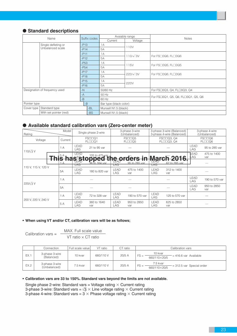
23
Available standard calibration vars (Zero-center meter)Model
Rating Single phase 2-wire 3-phase 3-wire (Unbalanced)
3-phase 3-wire (Balanced)3-phase 4-wire (Balanced)
3-phase 4-wire (Unbalanced)
Voltage Current FSQ1FLQ1
FSQ5FLQ5
FSQ3, Q4FLQ3, Q4
FSQ6FLQ6
110/3 V1 A LEAD
LAG 21 to 95 var — — LEADLAG 95 to 285 var
5 A LEADLAG 105 to 475 var — — LEAD
LAG475 to 1400 var
110 V, 115 V, 120 V1 A LEAD
LAG 36 to 164 var LEADLAG 95 to 285 var LEAD
LAG 62 to 285 var —
5A LEADLAG 180 to 820 var LEAD
LAG475 to 1400 var
LEADLAG
312 to 1400 var —
220/3 V1 A — — — LEAD
LAG 190 to 570 var
5A — — — LEADLAG
950 to 2850 var
200 V, 220 V, 240 V1 A LEAD
LAG 72 to 328 var LEADLAG 190 to 570 var LEAD
LAG 125 to 570 var —
5 A LEADLAG
360 to 1640 var
LEADLAG
950 to 2850 var
LEADLAG
625 to 2850 var —
• When using VT and/or CT, calibration vars will be as follows;
Calibration vars = MAX. Full scale value
VT ratio × CT ratio
Connection Full scale value VT ratio CT ratio Calibration vars
EX.1 3-phase 3-wire(Balanced) 10 kvar 660/110 V 20/5 A FS =
10 kvar= 416.6 var Available
660/11020/5
EX.2 3-phase 3-wire(Unbalanced) 7.5 kvar 660/110 V 20/5 A FS =
7.5 kvar= 312.5 var Special order
660/11020/5
• Calibration vars are 33 to 150%. Standard vars beyond the limits are not available.
Single phase 2-wire: Standard vars = Voltage rating Current rating 3-phase 3-wire: Standard vars = 3 Line voltage rating Current rating 3-phase 4-wire: Standard vars = 3 Phase voltage rating Current rating
Single defleting or Unbalanced scale
-P13 1A110V
-P14 5A
-P11 1A110/√3V For FS0Q6, FL0Q6
-P12 5A
-P53 1A115V For FS0Q5, FL0Q5
-P54 5A
-P17 1A220/√3V For FS0Q6, FL0Q6
-P18 5A
-P15 1A220V
-P16 5A
Designation of frequency used -N 50/60 Hz For FS0Q3, Q4, FL0Q3, Q4
-A 50 HzFor FS0Q1, Q5, Q6, FL0Q1, Q5, Q6
-B 60 HzPointer type -B Bar type (black color)Cover type Standard type -BL Munsell N1.5 (black)
With set pointer (red) -BS Munsell N1.5 (black)
Standard descriptionsName Suffix codes
Avaiable rangeNotes
Current Voltage
This has stopped the orders in March 2016.

24
Standard descriptionsName Suffix codes
Available rangeNotes
Current VoltagePower factor meters
Single phase 2-wire3-phase 3-wire
-C71 0.1 A
100 V
For FS0P1,P3,P5,FL0P1,P3,P5
Standard scale:LEAD 0.5 to 1.0 to 0.5LAG-C72 0.5 A
-C51 1 A -C52 5 A-C01 0.1 A
110 V-C02 0.5 A-C13 1 A -C14 5 A-C73 0.1 A
115 V-C74 0.5 A-C53 1 A -C54 5 A-C75 0.1 A
120 V-C76 0.5 A-C55 1 A -C56 5 A-C81 0.1 A
200 V-C82 0.5 A-C61 1 A -C62 5 A-C03 0.1 A
220 V-C04 0.5 A-C15 1 A -C16 5 A-C83 0.1 A
230 V-C84 0.5 A-C63 1 A -C64 5 A-C85 0.1 A
240 V-C86 0.5 A-C65 1 A -C66 5 A
3-phase 4-wire -C07 0.1 A
110/3 V
For FS0P6,FL0P6-C08 0.5 A
-C11 1 A -C12 5 A
Designation of frequency used -N 50/60 Hz For FS0P3,FL0P3-A 50 Hz For FS0P1,P5,P6
FL0P1,P5,P6-B 60 HzPointer type -B Bar type (black color)Cover type Standard type -BL Munsell N1.5 (black)
With set pointer (red) -BS Munsell N1.5 (black)
Product line-upModel
Dimensions(Width Height) Operating principle Accuracy class
FS, FLseries (Pivot and jewel)
Single phase 2-wire
3-phase 3-wire 3-phase 4-wire
(Balanced) (Unbalanced) (Unbalanced)FL80P1 FL80P3 FL80P5 FL80P6 8067 Phase defection type:
For single-phase and 3-phase (balanced)Feedback time division multiplier type: For 3-phase (unbalanced)
5.0
FL10P1 FL10P3 FL10P5 FL10P6 10083
FS60P1 FS60P3 FS60P5 FS60P6 6060
FS80P1 FS80P3 FS80P5 FS80P6 8080
FS10P1 FS10P3 FS10P5 FS10P6 100100
FS60P3
Power Factor Meters (With External Transducer)
Specify following information from when ordering.Code: Ex. FS60P3 − C14 − N − B − BL
———— —— — — ——Model Suffix
CodeDesignation of frequency
used
Pointer Cover color and set pointer
External transducer
This has stopped the orders in March 2016.

25
Standard ratingRating Usable
Voltage Current Voltage Current
110/3 V1 A
52 to 75 V0.3 to 1.2 A
5 A 1.5 to 6 A
110 V1 A
90 to 130 V0.3 to 1.2 A
5 A 1.5 to 6 A
220/3 V1 A
104 to 150 V0.3 to 1.2 A
5 A 1.5 to 6 A
220 V1 A
180 to 260 0.3 to 1.2 A
5 A 1.5 to 6 A

26
Dimensions and Panel Mountings
2071, 2081(unit: mm)
16±0.3 16±0.32-Ø3.5
Ø39 hole 20.4
13.9
±0.2
16±0
.316
±0.3
45.6+0.2
0
+0.50
+0.
20
Ø7 hole
+0.20 hole
15 25 14.5
10 13
Ø38
14
44*1.
5
20.2
±0.2
52*
45.4±0.2
Panel cut out
Surface mount Window Mount
32±0.2
1616
10.5
19 2-M3
2-M4
Weight: (Approx.) 60g
2072, 2082(unit: mm)
50.6 +0.20
22.9
14.9
±0.2
+0.
20
Ø7+0.5
0 hole
19±0.3 19±0.32-Ø3.5
Ø44 hole
19±0
.319
±0.3
+0.20 hole
1919
12.5
15 25 14.5
10 13
Ø43
152
48*22
.7±0
.2
57*
50.4±0.2
38±0.2
19 2-M3
2-M4
Panel cut out
Surface mount Window Mount
Weight: (Approx.) 70g
2073, 2083(unit: mm)
61.6+0.2
0
+0.
20
28.4
17.9
±0.2
Ø7+0.5
0 hole
24±0.3 24±0.32-Ø3.5
Ø46 hole27.5
±0.3
20.5
±0.3
+0.20 hole
27.5
20.5
11.5
15 25 14.5
10 13
Ø45
183
58*28
.2±0
.2
19 2-M3
2-M4
48±0.269*
61.4±0.2
Panel cut out
Surface mount Window Mount
Weight: (Approx.) 80g
Clearline Series
Dimensions marked with * are those of the cover rear, but those of the front become approximately 5546 due to draft.
Dimensions marked with * are those of the cover rear, but those of the front become approximately 5042 due to draft.
Dimensions marked with * are those of the cover rear, but those of the front become approximately 6756 due to draft.

27
2074A, 2084A(unit: mm)
(15.7) 17 25 14.5
1310
Ø52 22
.5
64±0.2
2-M4
2-M3
Safety terminal cover29.5
18.5
30
34.2
±0.2
69*
82*73.4±0.2
234 9
+0.
20
73.6 +0.20
34.4
22.9
±0.2
Ø7 +0.50 hole
32±0.3 32±0.32-Ø3.5
Ø53 hole29.5
±0.3
18.5
±0.3
+0.20 hole
Panel cut out
Surface mount Window Mount
Weight: (Approx.) 105g
2075A, 2085A(unit: mm)
Ø52 22
.5
(15.7) 17 14.5
10 13
2521
.542
.5
80±0.230
2-M4
2-M4
Safety terminal cover
93.4±0.2
25.5
85*44
.7±0
.2
6.5
102*9
+0.
20
93.6 +0.20
44.9
25.4
±0.2
Ø7 +0.50 hole
40±0.3 40±0.32-Ø4.5
Ø53 hole42.5
±0.3
21.5
±0.3
+0.20 hole
Panel cut out
Surface mount Window Mount
Weight: (Approx.) 130g
2076A, 2086A(unit: mm)
113.4±0.2
122*
32
102*
9.5 56
.2±0
.2
10 13
Ø52
22.5
100±0.2
30
609
20
2-M4
2-M4
Safety terminal cover
+0.
20
113.6+0.20
56.4
31.9
±0.2
Ø7+0.50 hole
50±0.3 50±0.32-Ø4.5
Ø53 hole
60±0
.320
±0.3
+0.20 hole
(15.7) 17 14.525
Panel cut out
Surface mount Window Mount
Weight: (Approx.) 160g
Dimensions marked with * are those of the cover rear, but those of the front become approximately 120100 due to draft.
Dimensions marked with * are those of the cover rear, but those of the front become approximately 8067 due to draft.
Dimensions marked with * are those of the cover rear, but those of the front become approximately 10083 due to draft.

28
Dimensions and Panel Mountings
2093A(unit: mm)
Panel cut out
Surface mount Window Mount
48±0.2
30
2-M3
2-M4
Safety terminal cover
2424
9
(15.7) 17
10
22.5
13
25 14.5
Ø52
Ø53 hole
24±0.3
24±0
.324
±0.3
24±0.3
Ø7 hole+0.5 0
30.4
+0.
2
0
52.6+0.2 0
17.4
±0.2
17.5
4
30.2
52.4
60*
60*
2-Ø3.5+0.2 0 hole
0-0
.3
0-0.3
Weight: (Approx.) 90g
2094A(unit: mm)
Panel cut out
Surface mount Window Mount
Ø7 hole+0.5 0
80*
21.5
4 40.2
80*
72.4
(15.7) 17
10 13
25 14.5
Ø62 22
.5
32±0.3
32±0
.332
±0.3
32±0.3
Ø63 hole
2-Ø3.5+0.2 0 hole
72.6 +0.2 0
40.4
+0.
2
021
.4±0
.2
64±0.2
3232
30
5
2-M3
2-M4
Safety terminal cover
0-0
.3
0-0.3
Weight: (Approx.) 115g
Dimensions marked with * are those of the cover rear, but those of the front become approximately 7878 due to draft.
Dimensions marked with * are those of the cover rear, but those of the front become approximately 5858 due to draft.
29
Unless otherwise specifi ed here, a dimensional tolerance is ±3% (±0.3 mm in case less than 10 mm).
FS, FL Series
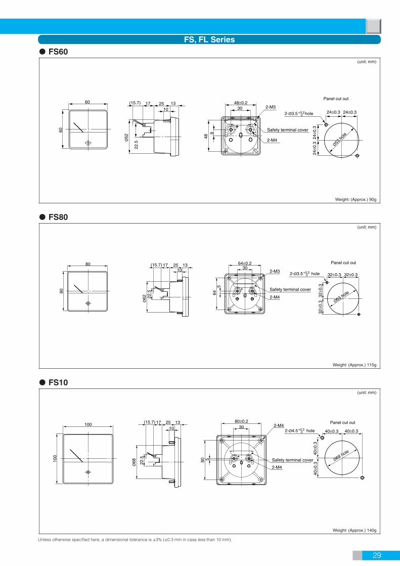
FS60(unit: mm)
++
30 2-M3
Safety terminal cover
48±0.2
489
Ø52
(15.7) 17 25 1310
22.5
60
60
24±0.3 24±0.3
24±0
.324
±0.3
2-Ø3.5 hole
Ø53 h
ole
Panel cut out
2-M4
+0.2 0
Weight: (Approx.) 90g
FS80(unit: mm)
+
302-M3
Safety terminal cover
2-M4
64±0.2
645
Ø62
(15.7) 17 25 1310
22.5
80
80
Panel cut out
+0.2 0
Ø63 hole
32±0.3 32±0.3
32±0
.332
±0.3
2-Ø3.5 hole
Weight: (Approx.) 115g
FS10(unit: mm)
+
2-Ø4.5 hole+0.2 0
Ø69 hole
40±0.3 40±0.3
40±0
.340
±0.3
Panel cut out100
100
(15.7) 17 25 1310
Ø68 22
.5
80
30 2-M4
Safety terminal cover
2-M4
80±0.2
5
Weight: (Approx.) 140g

Dimensions and Panel Mountings
Unless otherwise specifi ed here, a dimensional tolerance is ±3% (±0.3 mm in case less than 10 mm).
30
FL80(unit: mm)
+
30
Safety terminal cover
2-M4
32322-M3
18.5
29.5
3.5
22.5Ø
52
(15.7) 17 25 13
1081.4
68.4
Panel cut out
2-Ø3.5 hole+0.2 0
Ø53 hole
32±0.332±0.3
18.5
±0.3
29.5
±0.3
Weight: (Approx.) 105g
FL10(unit: mm)
+
Panel cut out
40±0.340±0.3
42.5
±0.3
21.5
±0.3
2-Ø4.5 hole+0.2 0
Ø53 h
ole
101.6
84.6
Ø52
(15.7) 17 25 1310
22.5
40 4030
2-M4
Safety terminal cover
21.5
42.5 1.5
2-M4
Weight: (Approx.) 130g
External transducer(unit: mm) (unit: mm)
M4
Oval shape hole6.5 10.5
6 2
16
10
10
100
18
140
0.5
160
12
4091
6.5 hole
Weight:(Approx.): Transducer FW1·Q1·P1, FP3: 290 gFW5·Q5: 480 g FQ3·P5: 340 g
For FW1·W5, FQ1·Q3·Q5, FP1·P3·P5
Weight:(Approx.): Transducer F4: 320 g F6: 370g
For FW4·W6, FQ4 ·Q6, FP6
M4
M4
Terminal Cover
2
16
10
10
(30)
(103)
100
18
160
12
4091
6 Oval shape hole6.5 10.5
6.5 hole
140
0.5

31
DC Ammeters, Voltmeters
AC Ammeters, Voltmeters
WattmetersSingle phase 2-wire FW1
3-phase 4-wire (Balanced) FW4 3-phase 4-wire (Unbalanced) FW6
3-phase 3-wire (Unbalanced) FW5LOAD
1S
P1 P2
1L
V
l
k
L
K
CT
U
v
uVT
2 1SOURCE
LOAD
1S 1L 2S 2L 3S 3L
P1 P0 P3
V
U
v
u
V
U
v
u
VT 123 NSOURCE
LOAD
1L1S
P1 P2 P3
3S 3L
V
U
v
u
V
U
v
u
VT 23 1SOURCE
CT
L
K
l
k
CT
L
K
l
k
CT
L
K
l
k
CT
L
K
l
kCT
L
K
l
k
LOAD
1S 1L 2S 2L 3S 3L
P1 P2 P0 P3
VU
vu
VU
vu
VU
vu
VT 123 NSOURCE
CT
L
K
l
k
CT
L
K
l
kCT
L
K
l
k
207(A)10208(A)10209A10,17FDAFDV
207(A)20208(A)20208(A)30209A20,27209A37FRAFSAFRVFSV
Ammeters Voltmeters
SOURCE LOAD
Ammeters Voltmeters
SOURCE LOAD
Shunt lead
externalmultiplier
external shunt
Ammeters Voltmeters
SOURCE LOAD1
2
Ammeters
<With CT, VT>
<With external shunt, multiplier>
Voltmeters
SOURCE LOAD1
2K L
CT
k l U VVT
u v
Voltmeters
SOURCE LOAD
HMETER
High-tension multiplier
<With high-tension multiplier>
Connection Diagrams

32
SOURCE LOAD1
2SOURCE LOAD
1
2U V
VTu v
Single phase 2-wire FQ1
Single phase 2-wire FP1
207A80209A80, 87FLFRFSFR
3-phase 3-wire (Balanced) FQ3
3-phase 3-wire (Unbalanced) FQ5
3-phase 3-wire (Balanced) FP3
3-phase 4-wire (Unbalanced) FP63-phase 3-wire (Unbalanced) FP5 LOAD
1S 1L 2S 2L 3S 3L
P1 P0P2 P3
VU
vu
Uvu
VU
vu
VT 123 NSOURCE
CT
L
K
l
k
CT
L
K
l
kCT
L
K
l
k
LOAD
1S 1L 2S 2L 3S 3L
P1 P0P2 P3
VU
vu
Uvu
V
V
Uvu
VT 123 NSOURCE
CT
L
K
l
k
CT
L
K
l
kCT
L
K
l
k
3-phase 4-wire (Unbalanced) FQ6
3-phase 4-wire (Balanced) FQ4LOAD
1S 1L 2S 2L 3S 3L
P1 P2 P3
V
U
v
u
V
U
v
u
VT 123 NSOURCE
CT
L
K
l
k
CT
L
K
l
kCT
L
K
l
k
LOAD
1L P2 P31S
V
U
l
k K
L
CT
v
uVT 23 1
SOURCE
LOAD
1L1S
P1 P2 P3
3S 3L
V
U
v
u
V
U
v
u
VT 23 1SOURCE
CT
L
K
l
k
CT
L
K
l
k
LOAD
1L1S
P1 P2 P3
3S 3L
V
U
v
u
V
U
v
u
VT 23 1SOURCE
CT
L
K
l
k
CT
L
K
l
k
LOAD
1L1S
P1 P2 P3
3S 3L
V
U
v
u
V
U
v
u
VT 23 1SOURCE
CT
L
K
l
k
CT
L
K
l
k
LOAD
1S
P1 P2
1L
V
U
v
uVT
2 1SOURCE
CT
L
K
l
k
LOAD
1L P2 P11S
V
U
l
k K
L
CT
v
uVT 2 1
SOURCE
Varmeters
Power factor meters
Frequency meters
Connection Diagrams

33
External shunt 2215, 2216, 2217
Model Rating
2215
01
50 mV
1 A02 1.5 A03 2 A04 3 A05 5 A06 7.5 A07 10 A08 15 A09 20 A10 30 A11 50 A12 75 A13 100 A14 150 A15 200 A16 300 A
221601
50 mV500 A
02 750 A03 1000 A
2217
01
50 mV
1500 A02 2000 A03 3000 A04 5000 A
Permissible tolerance: ±0.2% of rated valueRated voltage drop: 50 mV
External multiplier 2224, 2225, 2226, 2228
Model Rating Current Consumption
2224
01 50 V
1 mA
02 75 V03 100 V04 150 V05 300 V06 500 V07 750V
2225 00 1 kV
222601 1.5 kV02 2 kV03 3 kV
222801 5 kV02 7.5 kV
Permissible tolerance: ±0.5% of rated valueMeasuring method: 2224...2 terminal type 2225, 2226, 2228...3 terminal type
External VTModel 2267 2268
Rated Burden 15 VA 50 VAPrimary Secondary — —
220 V
110 V
2267 01 —440 V 2267 02 —1100 V 2267 03 —2200 V 2267 04 —3300 V 2267 05 2268 016600 V — 2268 02
Class: Equivalent to JIS C1731 Class 1.0Structure: Epoxy mold type
External CT 2255
Model Primary Secondary
2255
01 10 A
5 A(15 VA max.)
02 15 A03 20 A04 30 A05 50 A06 75 A07 100 A08 150 A09 200 A10 250 A11 300 A12 500 A
Class: Equivalent to JIS C1731 Class 1.0Structure: Epoxy model typeDielectric Strength: less than 3450V
External shunt, External multiplier, External VT, External CTAccessories
OtherShunt lead: 219930-24 (1.5 m, 0.05Ω)
110
175
45
150±0.4
30
Ø5.5
Ø12 spotfacing
M5
M617.5
6.5 14
.5
35.5
110
175150±0.4
Ø5.5
Ø12 spotfacing
50 M5
* M6
* 100 to 300 A are M8
6.5
14.5
H
10 to 100 A 39.5150 to 300 A 54.5
500 A 50750 A 64
130130
230230
5060
1,000 A 6417027084
30
A
M5 M12
6.5
WH
P32
2,000 A 123581503,000 A 205311770
1101,500 A 123574—92
120
M5 M12 Ø14
32
6
70054050
90 200
M5 M12 Ø14
27017032 3250
W
50 50
53 110
136
66
666
D
HC
*Dashed line is for 1,500 A
Q
2215 (1 to 7.5 A) 2215 (10 to 300 A) 2216 (500 to 1000 A)
2217 (1,500 to 3,000 A) 2217 (5,000 A)
Rating HRating HPAW
Rating DCHQW
Dimensions for accessories (unit: mm)
Model 2225 and 2268 is now order stop in March 2016.

34
Dimensions for accessories (unit: mm)
Ø108
Ø3.5
35±0.25
43
2863
7.5
5
646
76
968.5±0.5
Ø4.5
30
1kVMETER
11
15±1
180±1
56
17
147 3320.5
59.5
204 85
Primaryterminals M5
11
7
180±1
162120
210
2626
135
METER
u v
Ø120
112130
2 80110
168
200
32
208200
135
7
Fuse
Primaryterminals M5
200, 250 A 492515300, 500 A 5114020
5010 to 150 A 47251245
60180170
200
A
50982
100
t
K
1.6
K l
1012
975
A base mounting position can be changed by 90 horizontally.
d
80 B66
P
b
Ø110
u v
1.6 40
626
135
160
25
155140
Fuse
Secondary terminals M5
96110
Secondaryterminals M5
Secondaryterminals M5
2224 (50 to 750 V) 2225 (1 kV) 2226 (1.5, 2 , 3 kV)
2228 (5, 7.5 kV) 2255 (10 to 500 A/5 A) 2267 (220 to 3300 V/110 V)
2268 (3.3 to 6.6 kV/110 V)
Rating tdbPBA
Accessories

Orders scheduled stop List This has stopped the orders in January 2016.
AC Ammeters (Mean Rectifi er Type) FS10RA
WATTMETERS FS60W1, FS60W4, FS60W5, FS60W6, FS80W4, FS80W6, FS10W1, FS10W4, FS10W6 FL80W1, FL80W4, FL80W5, FL80W6, FL10W1, FL10W4, FL10W5, FL10W6
VARMETERS FS60Q1, FS60Q3, FS60Q4, FS60Q5, FS60Q6, FS80Q1, FS80Q3, FS80Q4, FS80Q5, FS80Q6 FS10Q1, FS10Q3, FS10Q4, FS10Q5, FS10Q6, FL80Q1, FL80Q3, FL80Q4, FL80Q5, FL80Q6 FL10Q1, FL10Q3, FL10Q4, FL10Q5, FL10Q6
POWER FACTOR METERS FS60P1, FS60P3, FS60P5, FS60P6, FS80P1, FS80P3, FS80P5, FS80P6, FS10P3, FS10P6 FL80P1, FL80P3, FL80P5, FL80P6, FL10P1, FL10P3, FL10P5, FL10P6
FREQUENCY METERS FS80FR, FL10FR
This has stopped the orders in March 2016.
DC Ammeters / Voltmeters • Suppressed Meters FS80DA, FS10DA, FS80DV, FS10DV
AC Ammeters / Voltmeters (Mean Rectifi er Type) 208220, 208320, 2084A20, 2086A20, 2094A27 FS80RA, FL80RA, FL10RA, FS80RV, FS10RV, FL80RV, FL10RV
AC Ammeters / Voltmeters (Moving Iron Type) FS10SA, FL80SA, FL10SA, FS80SV, FS10SV, FL80SV, FL10SV
WATTMETERS FS80W1, FS80W5, FS10W5
POWER FACTOR METERS FS10P1, FS10P5
FREQUENCY METERS 2074A80, 2075A80, 2076A80, 2093A80, 2094A80, 2094A87, FS60FR, FS10FR, FL80FR
Will be discontinued July 29, 2016.
DC Ammeters / Voltmeters • Suppressed Meters 207110, 207210, 207310, 2074A10, 2075A10, 2076A10, 208110, 208210, 208310, 2084A10 2085A10, 2086A10, 2093A10, 2094A10, 2093A17, 2094A17 FS60DA, FL80DA, FL10DA, FS60DV, FL80DV, FL10DV
AC Ammeters / Voltmeters (Mean Rectifi er Type) 207120, 207220, 207320, 2074A20, 2075A20, 2076A20, 208120, 2085A20, 2093A20, 2094A20 2093A27, FS60RA, FS60RV
AC Ammeters / Voltmeters (Moving Iron Type) 208130, 208230, 208330, 2084A30, 2085A30, 2086A30, 2093A37, 2094A37 FS60SA, FS80SA, FS60SV
FREQUENCY METERS 2093A87

• Before operating the product, read the instruction manual thoroughly for proper and safe operation.
NOTICE!