building time
TRANSCRIPT
LARGE HOSPITAL BUILDINGCONSTRUCTED IN RECORD TIMEBy Vasant S. Kelkar, Ashish Bhangle, Mehga Ghatwal
The floor finish was generally of ceramictiling and the internal walls were of lightweight Siporex blocks. ln some areashousing CT scan and MRI machines, 150thick RCC walls were required to beprovided.
The total construction area includingbasements is about 5,80,000 sq. ft. Theclients required that construction of thebuildings be completed within a period of 10-12 months.1.0 lntroduction
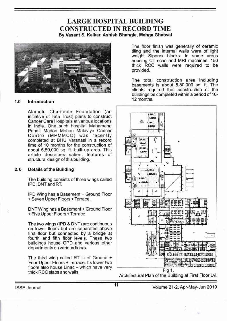
Alamelu Charitable Foundation (aninitiative of Tata Trust) plans to constructCancer Care Hospitals at various locationsin lndia. One such hospital MahamanaPandit Madan Mohan lvlalaviya CancerCentre (MPMMCC ) was recentlycompleted at BHU Varanasi in a recordtime of 10 months for the construction ofabout 5,80,000 sq. ft. built up area. Thisarticle describes salient features ofstructural design of this building.
Details of the Building
The building consists of three wings calledlPD, DNT and RT.
IPD Wing has a Basement + Ground Floor+ Seven Upper Floors + Terrace.
DNT Wing has a Basement + Ground Floor+ Five Upper Floors + Terrace.
The two wings (lPD & DNT)are continuouson lower floors but are separated abovefirst floor but connected by a bridge atfourth and fifth floor levels. These twobuildings house OPD and various otherdepartments on various floors.
The third wing called RT is of Ground +
Four Upper Floors + Terrace. lts lower twofloors also house Linac - which have verythick RCC slabs and walls.
2.0
Fig 1.
Architectural Plan of the Building at First Floor Lvl.
ISSE Journal Volume 21 -2,Apr-May-Jun 201 9

3.0 NDMA Guidelines for StructuralDesign of Hospital Buildings,
The hospital building was required to bedesigned following "National DisasterManagement Guidellnes" issued byNational Disaster Management Authority(NDMAXIl besides foilowing the relevantlS codes. NDMAguidelines are nruch moresevere than specifications of lS codesespecially for EQ loadings, the reasonapparently being that under a very severeEQ even if other buildings have failed thehospitals have to be functional to treat thecasualties of the disasterand hence shouldbe designed much more conservativelythan other buildings.
NDMA recommendations on the structuraldesign of hospital buildingsprohibit manytypes of construction such as flat slabfloors, floating columns, prestressed floorsystems, precast construction etc. Thelateralforces due to EQ are specified as:
Vo =AnW
where n. = ad
b]rro Vo= Base shear
The formula forAn above is similarto that inclause 6.4.2 of IS 1893 (Part 1:2016) l2lexcept that the factor 2 in the denominatorin the lS code formula is absent in theabove formula. This means that as perNDMA guidelines the building has to bedesigned for two times the earthquakeforces than those obtained for the samebuilding by IS 1893. ln addition, withimportance factor l=1.5, the lateralearthquake forces for the hospital buildingbecome three times those of a similarresidential or commercial building.
NDMA also specifies that"The total cross-sectional area of all RC Structural Wallsshall be at least 4% of the plinth area of thebuilding (if th'at based on design is smallerthan 4o/o), along each of the two mutuallyperpendicular principal plan directions".
This clause seems to be unreasonableconsidering that as per this clause:
4.0
a. ln the same earthquake zoneif thereare two buildings of different heights,say,one of 1 0 stories and the other of 20stories with about the same floor/plintharea, then stillfor both the buildings thesame areas of shear walls haveto beprovided = 4o/o of plinth area although inthe second building stresses due to EQloadswill be much higher.
b. lf there are two buildings which are verysimilar in height and plinth area but intwo different EQ zones, stillfor both thebuildings minimum shear wall area willhaveto bethesame.
ln ouropinion this clause in NDMAneedstobe amended. We were told by a member ofthe NDMA committee that they are givingsuch requirements based on some studiesof buildings in EQ Zone lV and then specifythem as a general requirement forbuildings in any zone. This needs to bechanged in amended guidelines.
Structural Scheme
The columns were placed on a grid ofabout8.5 x8.5m as per architecturalrequirement. Flat slabs are not permissibleand hence a structural arrangement withR.C.C. slab and beam structuie with RCCcolumns and shear walls was possible.However, considering the stringent timeconstraint for completion of the building, itwas decided to design the main structuralelements in structural steel to facilitatespeedy construction although it wouldmean a higher cost compared to a normalRCC structure.
Thus, the floors were designed as RCCslab supported on metal deck and steelbeams which spanned between steelcolumns. The thickness of slabwas150mm (90mm flange + 60mm ribs).The secondary steel beams were mainlybuilt up I sections of 460mm depthsupported on main beams which varied insizes but were generally built up I sectionsof 600mm depth. Some beams were alsoof lesser or more depths. The slab andbeams were connected by steel studs tomake them act as composite sections.
ISSE Journal12 Volume 21 -2, Apr-May-Jun 201 9

The columns were generally bL:itsections of 400mrn depth and .150
flanges. On higher floors the s zes werereduced. They were encased n ccncretewith steel reinforcement ari weredesigned as composite columns
The RT wing the area hoi,,s .g r-inac hadwalls and slabs more tlar' lm th ck tocontrol radiations,
For lateral load resistarce siee C agonalbraces inside the building .' or :s raQadewere not possible arci^ ie.:-'a ! ience.for lateral load resistance s- aa' ,',a s ,,,,/ere
provided and also maa_. :':-= -; - :ea.rswere connected to s:=: :: -
^--: .', :-moment connectior-s " -: :- = =
.: -: a2aresisting system cc-: s:=l :'s-3a' ,,,a swith steel momen: ':s :: -: "a*es F',,,en
though lS code spr:':= =.=5 fcr a dualsystem consistir^3 c's-3a. l,'a s + momentframes, R=-1 ,',as consrderedconservativel,v' as i ,'ias diflicult to designthe steel frames to resist minimum 25% ofthe base shear, considering that lateralforces due to EQ were much too high forthis building using NDMA guidelinei andimpoftance factor of 1 .5.
The concrete grade was M30 for deck slaband M40 for other members.Reinforcement was with Fy = 500N/mm'.Structural Steel was with Fy = 350 N/mm'and for some members even steel with Fy =450N/mm'was used
The structural la5iout of the second floor isshown inFig.2.
Analysis of the whole structure was doneusing Etabs software.
The soil reporl showed that raft foundationwith a SBC = 2{.STlm'?could be used.Hence, the foundations were designed as a1200mm thick raft in IPD/DNT building and1000mm thick raft in RT building. Raftswere analyzed with SAFE softwareconsidering soil as springs with stiffnesscorresponding to modulus of sub grade
Fig.2.Structural Layout of the Second Floor Lvl.
reaction. The water table level at the sitewas much below the ground level andhence there was no difficulty in carrying outthe construction of foundation and retainingwalls with open excavation.
For fire resistance the internal steel beamswere covered with vermiculite. The beamsof facades were encased in concrete.
Gontrolof Vibrations
Floors consisting of long span steel beamscan lead to uncomfortable vibrationsexcited due to human activities on the floorsuch as walking within the rooms or inadjoining corridors. lndeed, such vibrationscan be experienced on airport or mall floorswith long span steel beams and on footbridges. Considering that frequency of theforcing function due to human movement is
uplwide
!
t
I
5.0
5.1
13ISSE Journal Volume 21 -2,Apr-May-Jun 20'1 9

generally between 1.5 to 2.5 Hz it waschecked during the design stage that thefundamental frequencies of vibrations ofthe floors were higher than 3Hz.
However, after most of the structure wasconstructed we were given the limits onvelocities and accelerations to becontrolled in some bays on the second floorwhere MRI and CT scan machines were tobe installed. The limits were specified bythe vendors GE Health supplying themachines.
Hence, further study was done using AISC(American lnstitute of Steel Construction)Design Guide Services article "FloorVibrations Due to Human Activity" [4]. TheConcrete Society Publication [5]also givesguidelines for calculating footfall inducedvibrations.
Operations of a sensitive machine can beaffected due to floor vibrations caused bypersons walking in the room where themachine is located or in adjoining corridors.Also, vibrations of floors can causediscomfort to persons working in the area.
Natural frequencies of the floor and theresulting vibrations will vary with the actualloads present.Hence,realistic values ofSDL = 3KN/m' and L.L. = 0.5KN/m' (+machine loads) in the bays wheremachines were to be located wereconsidered to obtain the naturalfrequencies of the floor - although designloads were of higher values.
5.2 VibrationsforHumanGomfort
i. As per AISC Design Guide [4], forhuman comfort the peak accelerationwhen a person of weight 70k9.(157lbs)iswalking should be lessthan 0.5%9.
The Concrete Society Publication[5] and ISO 2631 -2, 1989 give thresholdvalues of RMS accelerations for humanperception. AISC guide considers peakaccelerations as multiPle of RMSvalues. The multiplying factor varies forresidences, malls or tootbridges etc.
and is taken as 10 for residential andoffice areas.
ii. Forconsideration of human comfort,values of peak acceleration due to aperson walking are calculated at thecenterofa bay.
As perAlSC guide peak acceleration due towalking can be estimated by the formula
P.e( -0.35fn)---w-Where oo = estimated peak acceleration,
g = gravity acceleration,f" = natural frequency of the floor
structure,
B = damping ratio. DamPingassociated with floor sYstems isrecommended = 0.03 for floorswith small demountable partitionsas in typical modular offices and =0.05 for floors with full heightpartitions between floors,
Po = a constant force = 0.29 KN forfloors and 0.41KN forbridges, for a person of70 Kg weight walking onthe floor,
\y'1/ = Effective weight of the floor (in thearea underconsideration).
ln the present case, there are walls of fullfloor height and hence damPing wasconsidered = 0.05. Value of floorfrequencywas obtained from ETABS analysis whichgives different values for different modeshapes of floor structure. The value whichshows a fundamental mode in the baYunder consideration was used as f". Thepeak accelerations thus obtained werewithin limits.
Since the floors were already constructed(although without partition walls etc.) fewtests were done at site by having pbrsonswalk at different speeds on the floor andcheck if any uncomfortable vibrations werefelt by other Persons. No suchuncomfortable vibrations were felt.
,o=g
ISSE Journal Volume 21 -2, Apr-May-Jun 201 9

5.3 Vibrations for Smooth Operation ofSensitive Machines
Machines like CT scan and MRI are verysensitive and give improper images ifsubjected to vibrations from floor. lt isdesirable that they are placed on theground floor (without basement). But in thepresent building they were located on thesecond floor.
As perAlSC guidelines [4]:
i. The values of acceleration and velocitieson the floor are considered due to a personweighing 84kg walking at a) fast pace (100steps/min.), b) moderate pace t75steps/min.) and c) slow pace (50steps/min.),
ii. For movement of persons within theroom where a sensitive machine is located,the walking speed will be that of slow pace.Only in any conidors near the locations ofthe machines the walking speed could beconsidered asfast, as perAlSC.
AISC Guide gives criteria for limitingvibration velocity for difierent types ofequipment such as Computer Systems,Bench Microscopes,MicrosurgeryEquipment, Electron Microscopes etc. Thevendor in the present hospital had giventhe limitations for smooth operation of theCTscan, MRI machines as:
mEx. ac@leration = 25mm/sec'= 0.0259(as against 0.59 for human comfort) andmax. velocttY = 4Ommisec (micrometer /sec) which was similar to that given forBench microscopes, optical and otherprecision balances etc. inAlSC guide.
AISC Guide gives max. displacement as
,* _ FmAp ,4,,*- 2 \fn'/
Where F, is a footfall impulse parametertaken as1.4,1.25and 1.1 KN respectivelyfor fast, moderate and slow walkingconditions for a walking person of 84 kg
weight.Corresponding f"values are given inAISC guide as 5.0, 2.5 and 1.4 Hzrespectively.
Ao is the deflection of the structure at thelocation of the machine under a unit loadwhich were obtained from analysis of thefloor structure. After calculating X,", fromabove, max. velocity V max and maxacceleration ap are obtained by therelations:
Vmax = 2(fl)f" X,",ap = 4(IIffnX.,*
Using the above equations, it was foundthat under slow walking condition theacceleration and velocity were withinallowable limits. But there were longcorridors adjoining various rooms in whichthe machines were to be placed. Hence,vibrations due to brisk walking of persons inthe long corridors had to be considered.
It was found that for brisk walking ofpersons in the corridors, the maximumvelocity and accelerations were beyond thespecified limits.
RemedialAction
To reduce vibrations of a floor, AISC guidealso suggests remedial measures such asstiffening of steel beams by adding coverplates at bottom or adding below it queenpost type truss members, addition ofcolumns etc.
ln the present case the following changeswere made:
i) The locations of the machinqs (notyet installed)were shifted to be onstiffer main girders and as close tocolumns as possible instead of in thecenter of bays. This reduces values ofAo in the above equation and henceX,"*. The architects changed the roomplans accordingly.
5.4
ISSE Journal 15Volume 21 -2, Apr-May-Jun 20 1 9
ii)
iii)
ln addition, A type steel bracingswere proposed below the girderssupporting the machines so as tominimize value of Ao to almost zero inthe above equation thereby reducingV,", and ao. Since the floor below wasa service floor, provision of bracingswas possible.
For minimizing brisk walking in thecorridors AISC Guide alsorecommends creating obstacles suchas reception tables etc. in thecorridors to reduce brisk walking. Butthis was not practical in the presentcase and hence not done.
After these changes it is expected that themachineswhen installed will operatesmoothly as desired.
It was, however,not possible to checkvibrations of the floors in the areas of themachines due to operation of hospitalpower plants, ac units, pumps/motors,elevators etc.
The construction of the building was startedwith excavation for foundations in the firstweek of April 2018 and completed by end ofFeb 2019. lt was inaugurated by P.M.Narendra Modi on 19.02.2019. The totaldesign and construction time was unusuallysmall for construction of a building with suchlarge area.
6.0
" .,q" l,i;b ;gffi;ffifr €ffi ,+hW"-.,. ,.: F, "p*!Elli$e{l s$ed i*ddr*3${&' ,'1. '#? ffi# :ffiE .d#*ffiffi, *'. tfi[-*ffi$ diffi &g:#ffi* ':AF:J
-Y-{5 "W&#Eg
g-
Book of Reesrd*7 t!rs ::r,i.t;,tri! i:,t/, iilrrr r,:l:a*rrf lr**3$
Ji
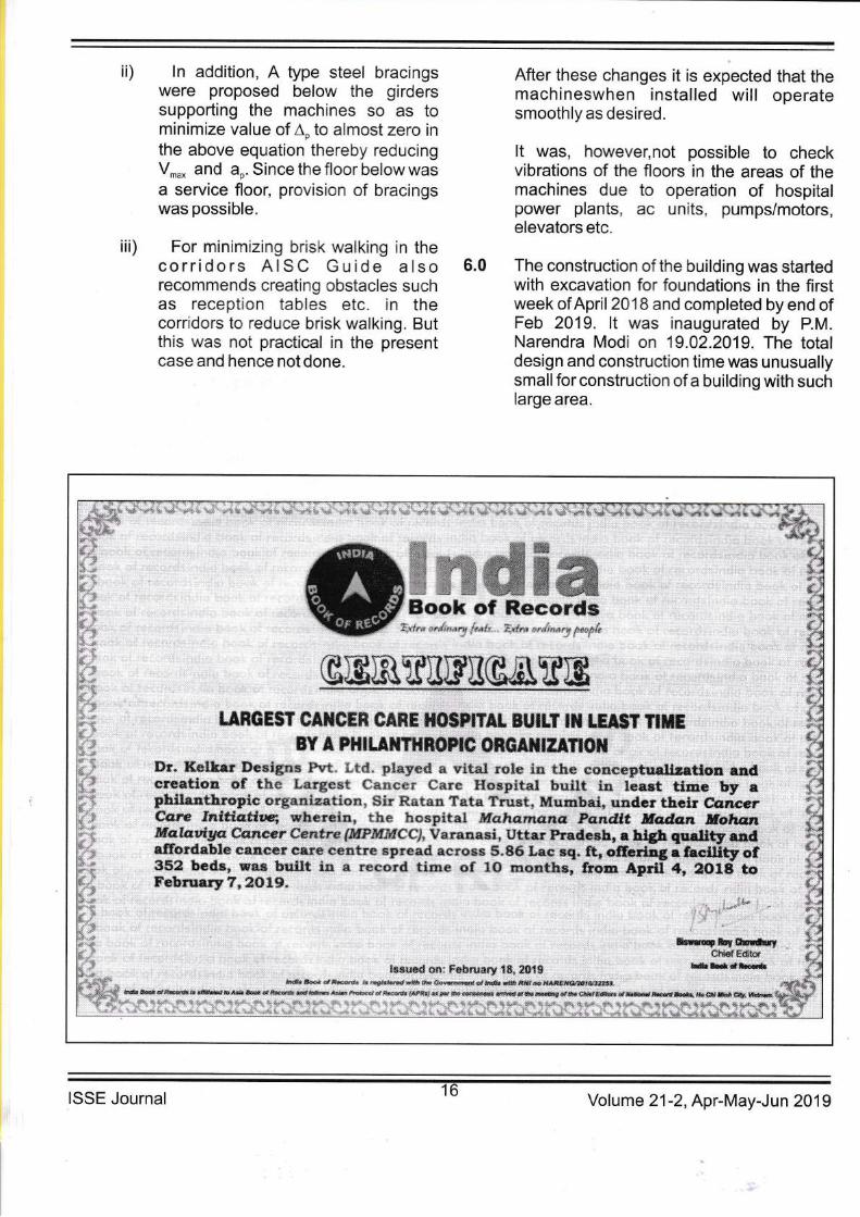
ffiffiffiK&ry& ewffit"**Bg3T CtilCrR CARr I{0$pNTAL BUTLT rt tg**T mmE
EY * pHrlStrTXBSr$ Oxfi*l$g*Tt**Br, !{*Xk*r Se*ig:rs F:rt. Lt{6.. pSep** a v{ts* r*r!* lsr *ke e*m**ptudix*t*on eadcreatiqa ef th* Largest fa::**r car* H*xpitat built in lea*t time by apkil*a*hru;li* *rganizatioa. Sir €atan Tata Trust, *lumbai, uader thelr Ccrcerc{3re "[nltdc**rq rrh*rein, thE h*spitai Mahama.na ps.ndtt Madan .lfalrsa,fifirllradgm #*ncsr ffera*re $?f?btlyIccl Yaranasi, Uttar Pradxsh, a ri$ qrralier andaIlbrdabtr* sa,rl*sr c&re rentre spread acrsss 5.86 La* *{. &, afial*rg i AeU[ty of35-2 beds, was built r* * r*"ord time of lO mootfrs, f;;E;f ;rl0ili;February 7,zALg.
&*ryer&6*ftrf*h'd{ tr*l{*r
b**t**da*r*is*a;ed **; Fxbruary tS, !0tS,lil{*s *d 6, ,f*@ & r€$*e&6SS dS lt!6 S8i*'@r*tei& qdBi Xrtr * }lrrg(*{&Ster&Xi*.
d&"eades*e.&W&*id.6**d*6.es&@&4id9@l*ffiq**ptu@i#*r$dss{@t dewf,ffi6@kd*r*i&rsda*6*&&(14*!e
ISSE Journal 16Volume 21 -2,Apr-May-Jun 20'l 9

Credits:
Architects
Structu ral Consultants
MEP ConsultantsPMCMain Contractor
Structural SteelFabrication,Design and Erection
References:
: EdificeConsultants Pvt. Ltd.
: Dr. Kelkar DesignsPvt. Ltd.
: Bluestar lndia Ltd.: Clancy Global: Capacite
lnfraprojects Ltd.
: JSW SeverfieldStructures Ltd.
About The Authors
Dr. Vasant S. KelkarDirector -Dr. Kelkar Designs Pvt. Ltd.Email ld:vasant. kel kar@kel kardesi g n s. com
Mr. Ashish BhangleDirector -Dr. Kelkar Designs Pvt. Ltd.Email ld:ash ish. bha n g le@kel kardesig ns. com
Ms. Megha GhatwalAssociate -Dr. Kelkar Designs Pvt. Ltd.Email ld:meg ha. g hatwal @kel kardesi g ns.com
1.
2.
3.
4.
5.
"National Disaster Manage-ent Guidelines -Hospital Safety by NDMA l"iai onal DisasterManagementAuthority)lS 1893 (Part 1):2016 C.:e 'a'ci EarthquakeResistant Design of Struc:u'eslS 13920: Ductile Desg- aic Detailing ofReinforced Concrete St'l::*"es Subjecte"d toSeismic Forces - Code :' :'a ltice.Murray, Allen and Unga' = .'i: Vibrations Dueto Human Activity S:ee )esign Guide ll,A1sc,2003.Willford and Your^; : )esign Guide forFootfall Induced \,/3'a:3'- 3f Structures", TheConcrete Societ,l, L3-:l^ 2t-rO6.
6. Davis, "Steel ='a* e. Floor DesignVibration Sens:,e E:I pment", AISCUniversity of Ke. :- :,1_, Pu bl ication, 2016.
forand