building professional services - bentley communities · in both xm and v8i, this tool is ......
TRANSCRIPT

Creating Drawings in Bentley Building Electrical Systems and the USACE Dataset. Page 1 of 20
How to create Drawings from your models using Bentley Building Electrical Systems and the USACE Dataset:
The Electrical Discipline Master Model: The Discipline Master Model is simply a file that references all of the files in your project that pertain to your discipline. It has 2 main uses: First, it is the only file that the other disciplines will reference in order to see the Electrical work. Second, it is where we will generate our 2d drawings or extractions from the 3D model that we have just built.
Create a discipline master model in your discipline: 1. Create a new file. Name the file per the standards that the USACE District office you are working for has
provided to you. The file naming standards can also be found in the 09Q4a version of the dataset in the Excel file: …\Con_Docs\_Standards\Proj_Stds\data\BIMNamingMatrix_5‐2009.xls
2. Reference all the electrical design models into the file. This will include all floors of the Lighting, Power, Systems and Grounding models. If you have multiple buildings you should create a separate Discipline master for each building.
You should only reference the electrical files into the Electrical Discipline Master Model. Do not reference any of the other Disciplines.
Import the USACE levels into the Discipline Master file: 1. Import the Electrical, Telecommunications and Fire Protection
level dgn libraries:
• Open Level Manager using the Icon in the Primary Tool Bar.
• In the Level Manager Dialog, Choose Levels, Import in the menu. The Import Levels dialog will open.
Building Professional Services

Creating Drawings in Bentley Building Electrical Systems and the USACE Dataset. Page 2 of 20
• Browse to the location of the USACE level dgn libraries. The Level DGN Libraries are stored in the USACE workspace Standards folder. This may be on a different drive from your project. They will be in the:
\USACE_Dataset_09Q4a\Workspace\Standards\dgnlib\ folder. Talk to your BIM Manager to find the exact location at your site.
• Select the USACE_Electrical.dgnlib file and click Open. The Level/Filter Import Dialog will open.
• In the Level/Filter Import dialog, the levels in the selected dgn library are selected. Click OK to import all of the levels into your Discipline Master Model.
• Repeat the import steps for the USACE_Telecommunications.dgnlib and the USACE_Fire_Protection.dgnlib files.
• Now that you have all of these levels imported, your drawings should extract to the correct levels. Because these levels are unused in the Discipline Master Model, you will need to re‐import them if you compress this file.
Creating Drawings in Bentley Building Electrical Systems and the USACE Dataset. Page 3 of 20
Drawing Extraction Manager:
Create an Extraction Drawing Definition for a Lighting, Power or Telecommunications Plan:
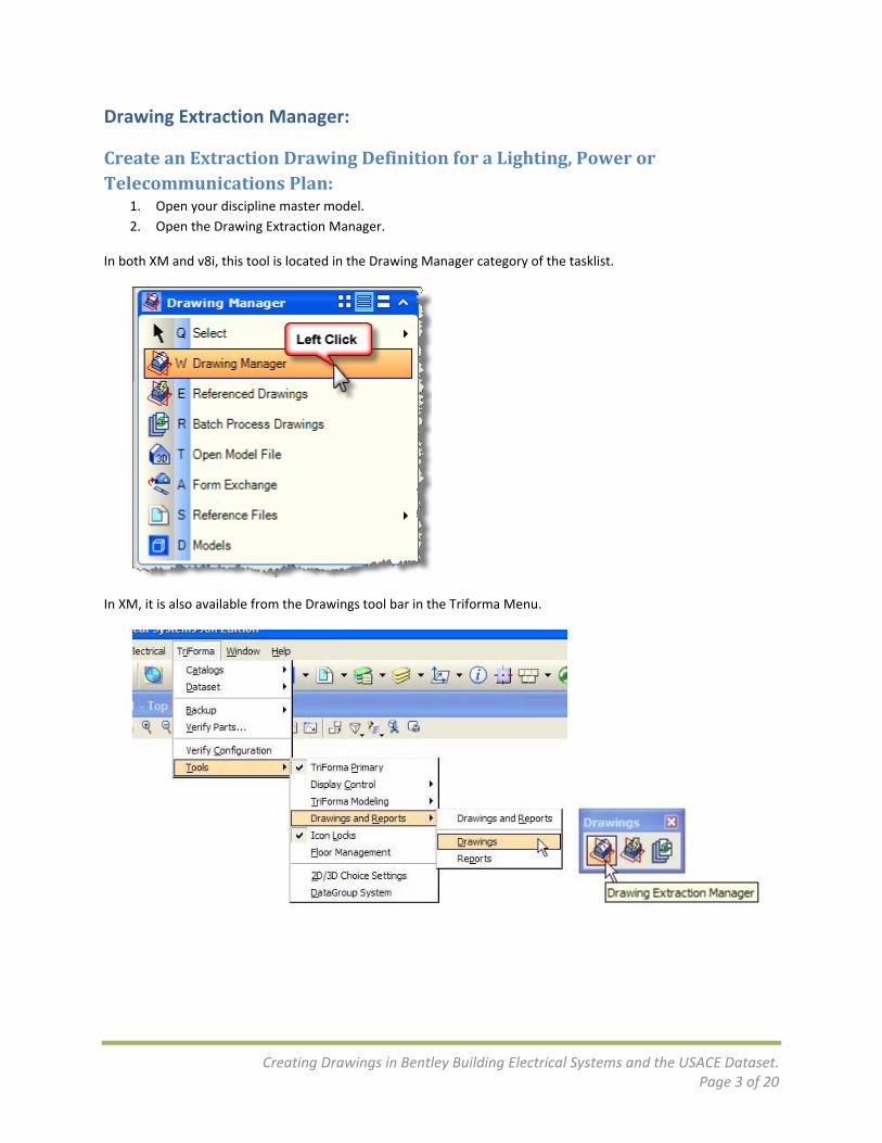
1. Open your discipline master model. 2. Open the Drawing Extraction Manager.
In both XM and v8i, this tool is located in the Drawing Manager category of the tasklist.
In XM, it is also available from the Drawings tool bar in the Triforma Menu.
Creating Drawings in Bentley Building Electrical Systems and the USACE Dataset. Page 4 of 20
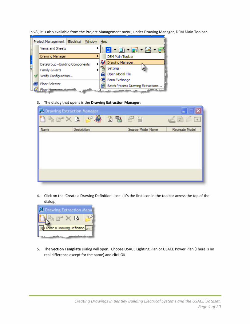
In v8i, it is also available from the Project Management menu, under Drawing Manager, DEM Main Toolbar.
3. The dialog that opens is the Drawing Extraction Manager:
4. Click on the ‘Create a Drawing Definition’ Icon (It’s the first icon in the toolbar across the top of the
dialog.)
5. The Section Template Dialog will open. Choose USACE Lighting Plan or USACE Power Plan (There is no
real difference except for the name) and click OK.

Creating Drawings in Bentley Building Electrical Systems and the USACE Dataset. Page 5 of 20
6. The Edit Drawing Definition dialog will open. The General tab, along the left‐hand side of the dialog, is
active.
On this tab, you will provide a name and description for the extraction’s drawing definition. The extraction will create a file that will have the same name as the drawing definition.
• Change the name to an appropriate name base on the USACE file naming standards. Highlight the name, right‐click and choose copy. We will need the name again later in the process.
• Enter a description for the Lighting Plan.
• The Drawing Output Directory should be set to $(TF_DRAWINGS). This is a configuration variable that points to the Electrical Extractions folder.
• Pick the Annotation Scale for the scale of the final drawing that you want to create.
Creating Drawings in Bentley Building Electrical Systems and the USACE Dataset. Page 6 of 20
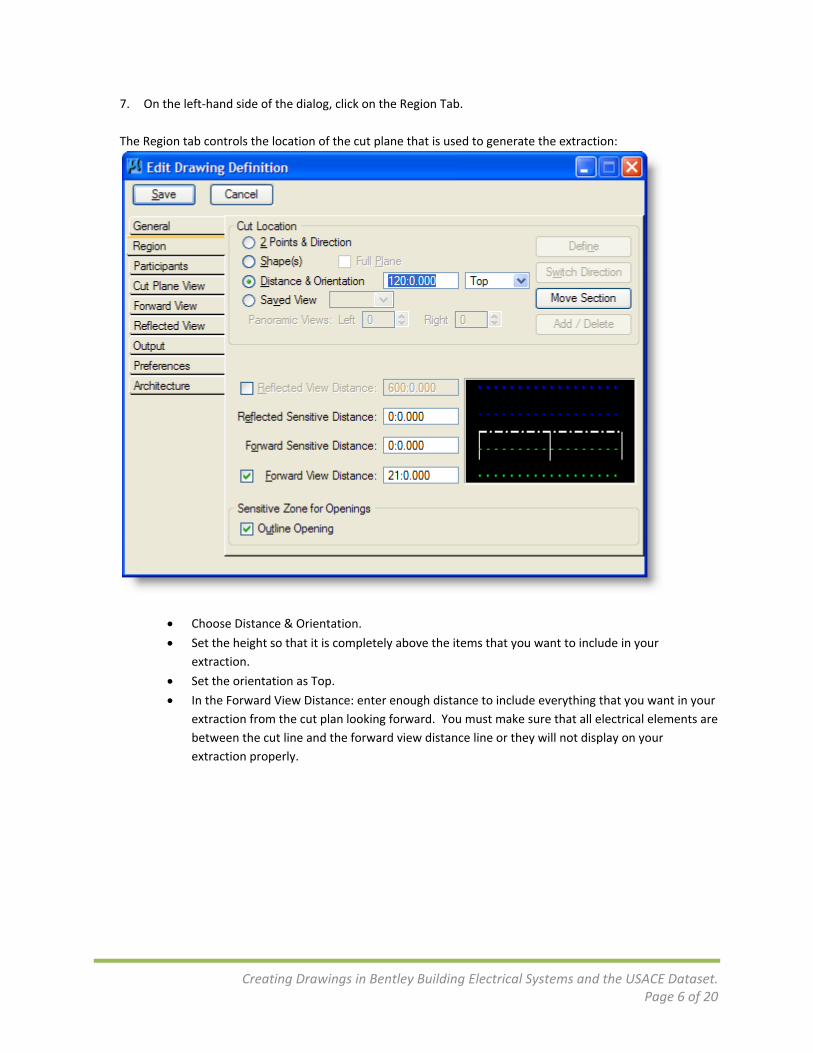
7. On the left‐hand side of the dialog, click on the Region Tab. The Region tab controls the location of the cut plane that is used to generate the extraction:
• Choose Distance & Orientation.
• Set the height so that it is completely above the items that you want to include in your extraction.
• Set the orientation as Top.
• In the Forward View Distance: enter enough distance to include everything that you want in your extraction from the cut plan looking forward. You must make sure that all electrical elements are between the cut line and the forward view distance line or they will not display on your extraction properly.

Creating Drawings in Bentley Building Electrical Systems and the USACE Dataset. Page 7 of 20
8. Click on the Participants tab. The Participants tab controls which elements to include in the extraction. Our 2 choices are to include only the active file (Process Master File Only) or to include a set of reference files (Process a Reference Group Model). Since there are no elements in the Discipline Master Model, we will always choose Process a Reference Group Model.
• Choose ‘Process a Reference Group Model’.
• Click on New.
• In the Group Model Dialog, click in the Name field, then right‐click and choose Paste. This will paste in the name of the extraction that we saved earlier. Naming the Group Model the same as the extraction is a good idea as you start out working with extractions.
• Give your reference a Description. This should probably be the same as your extraction description.
• Press OK. This will create a new model in the Discipline Master Model that contains the same reference files as the Default Model.
Creating Drawings in Bentley Building Electrical Systems and the USACE Dataset. Page 8 of 20
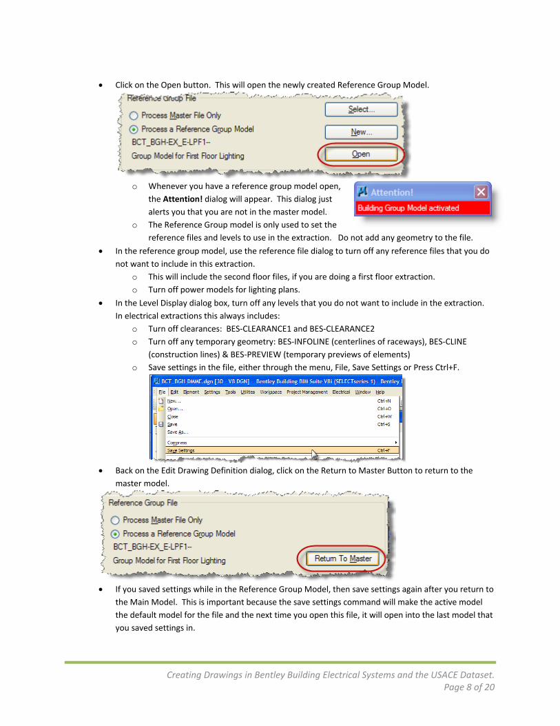
• Click on the Open button. This will open the newly created Reference Group Model.
o Whenever you have a reference group model open,
the Attention! dialog will appear. This dialog just alerts you that you are not in the master model.
o The Reference Group model is only used to set the reference files and levels to use in the extraction. Do not add any geometry to the file.
• In the reference group model, use the reference file dialog to turn off any reference files that you do not want to include in this extraction.
o This will include the second floor files, if you are doing a first floor extraction. o Turn off power models for lighting plans.
• In the Level Display dialog box, turn off any levels that you do not want to include in the extraction. In electrical extractions this always includes:
o Turn off clearances: BES‐CLEARANCE1 and BES‐CLEARANCE2 o Turn off any temporary geometry: BES‐INFOLINE (centerlines of raceways), BES‐CLINE
(construction lines) & BES‐PREVIEW (temporary previews of elements) o Save settings in the file, either through the menu, File, Save Settings or Press Ctrl+F.
• Back on the Edit Drawing Definition dialog, click on the Return to Master Button to return to the
master model.
• If you saved settings while in the Reference Group Model, then save settings again after you return to
the Main Model. This is important because the save settings command will make the active model the default model for the file and the next time you open this file, it will open into the last model that you saved settings in.
Creating Drawings in Bentley Building Electrical Systems and the USACE Dataset. Page 9 of 20
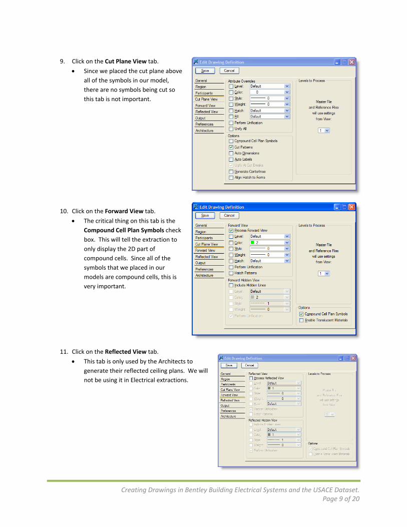
9. Click on the Cut Plane View tab.
• Since we placed the cut plane above all of the symbols in our model, there are no symbols being cut so this tab is not important.
10. Click on the Forward View tab.
• The critical thing on this tab is the Compound Cell Plan Symbols check box. This will tell the extraction to only display the 2D part of compound cells. Since all of the symbols that we placed in our models are compound cells, this is very important.
11. Click on the Reflected View tab.
• This tab is only used by the Architects to generate their reflected ceiling plans. We will not be using it in Electrical extractions.

Creating Drawings in Bentley Building Electrical Systems and the USACE Dataset. Page 10 of 20
12. Click on the Output Tab: • The settings on this tab are set
for you in the template you selected earlier.
13. Click on the Preferences Tab: • On this tab, it is important that
Never Hide Text / Spaces is turned on if you are using a filled font(like Arial) for your subtype and circuit number labels. If this is not on, the filled fonts will be drawn as outlines.
14. Click on the Architecture Tab: • This tab contains settings only for the
Architects and is not used in BBES.

Creating Drawings in Bentley Building Electrical Systems and the USACE Dataset. Page 11 of 20
15. On the upper left‐hand corner of the Edit Drawing Definition dialog, click on Save.
16. Select your Extraction Definition in the Drawing Extraction Manager List and click on the Calculate All
button in the upper right‐hand corner of the dialog. (It looks like a pencil on a drafting board.)
17. Your drawing will now be created and saved into the extractions folder
for your discipline. A preview of the drawing will open in View 8. You can open the Drawing by clicking on the Open button. (It looks like an opening folder.)
Creating Drawings in Bentley Building Electrical Systems and the USACE Dataset. Page 12 of 20
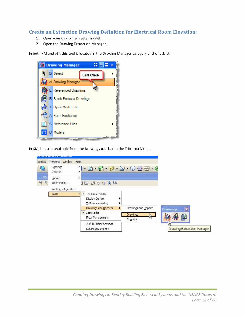
Create an Extraction Drawing Definition for Electrical Room Elevation: 1. Open your discipline master model. 2. Open the Drawing Extraction Manager.
In both XM and v8i, this tool is located in the Drawing Manager category of the tasklist.
In XM, it is also available from the Drawings tool bar in the Triforma Menu.

Creating Drawings in Bentley Building Electrical Systems and the USACE Dataset. Page 13 of 20
In v8i, it is also available from the Project Management menu, under Drawing Manager, DEM Main Toolbar.
3. The dialog that opens is the Drawing Extraction Manager:
4. Click on the ‘Create a Drawing Definition’ Icon (It’s the first icon in the
toolbar across the top of the dialog.) 5. The Section Template Dialog will open. Choose
USACE Electrical Room Elevation and click OK.
Creating Drawings in Bentley Building Electrical Systems and the USACE Dataset. Page 14 of 20
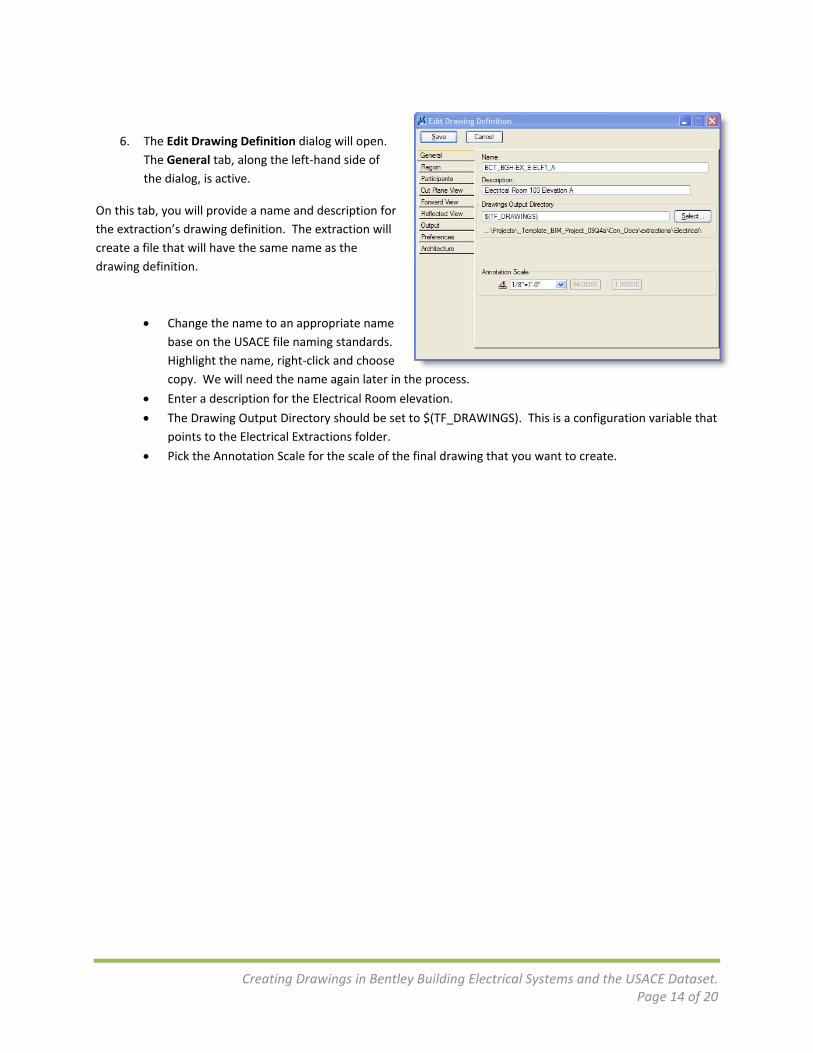
6. The Edit Drawing Definition dialog will open.
The General tab, along the left‐hand side of the dialog, is active.
On this tab, you will provide a name and description for the extraction’s drawing definition. The extraction will create a file that will have the same name as the drawing definition.
• Change the name to an appropriate name base on the USACE file naming standards. Highlight the name, right‐click and choose copy. We will need the name again later in the process.
• Enter a description for the Electrical Room elevation.
• The Drawing Output Directory should be set to $(TF_DRAWINGS). This is a configuration variable that points to the Electrical Extractions folder.
• Pick the Annotation Scale for the scale of the final drawing that you want to create.
Creating Drawings in Bentley Building Electrical Systems and the USACE Dataset. Page 15 of 20
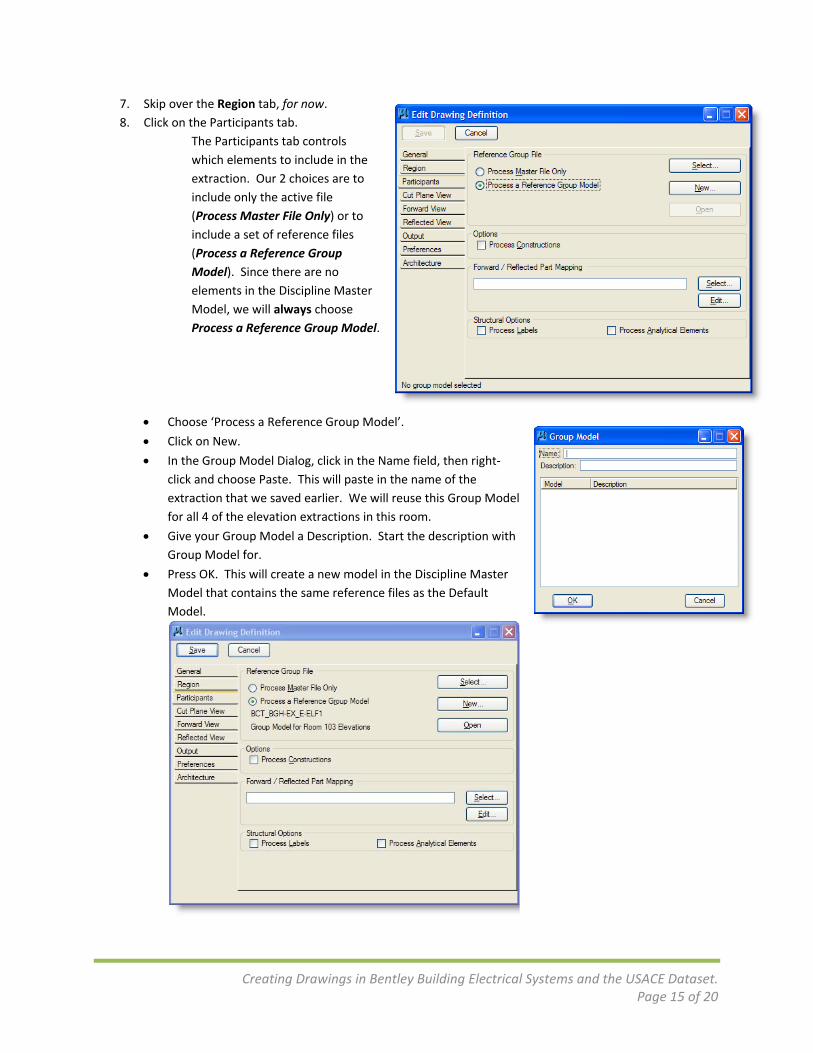
7. Skip over the Region tab, for now. 8. Click on the Participants tab.
The Participants tab controls which elements to include in the extraction. Our 2 choices are to include only the active file (Process Master File Only) or to include a set of reference files (Process a Reference Group Model). Since there are no elements in the Discipline Master Model, we will always choose Process a Reference Group Model.
• Choose ‘Process a Reference Group Model’.
• Click on New.
• In the Group Model Dialog, click in the Name field, then right‐click and choose Paste. This will paste in the name of the extraction that we saved earlier. We will reuse this Group Model for all 4 of the elevation extractions in this room.
• Give your Group Model a Description. Start the description with Group Model for.
• Press OK. This will create a new model in the Discipline Master Model that contains the same reference files as the Default Model.

Creating Drawings in Bentley Building Electrical Systems and the USACE Dataset. Page 16 of 20
• Click on the Open button. This will open the newly created Reference Group Model.
o Whenever you have a reference group model open,
the Attention! dialog will appear. This dialog just alerts you that you are not in the master model.
o The Reference Group model is only used to set the reference files and levels to use in the extraction. Do not add any geometry to the file.
• In the reference group model, use the reference file dialog to attach the other Discipline Master Models that will need to be seen in your extraction. This will always include Architecture; Structural and Mechanical are only needed if they are exposed in the Electrical Room.
o Use Live Nesting with a depth of 99
• In the reference group model, use the reference file dialog to turn off any reference files that you do not want to include in this extraction.
o This will include the second floor files, if you are doing a first floor extraction.
• In the Level Display dialog box, turn off any levels that you do not want to include in the extraction. o In electrical extractions this always includes:
Turn off clearances: BES‐CLEARANCE1 and BES‐CLEARANCE2 Turn off any temporary geometry: BES‐INFOLINE (centerlines of raceways), BES‐
CLINE (construction lines) & BES‐PREVIEW (temporary previews of elements) o Save settings in the file, either through the menu, File, Save Settings or Press Ctrl+F.
9. We will now create a shape in the Reference Group Model that will establish the cut plane for the
extraction.
• Use the Floor Selector to set the correct ACS plan for your electrical room.
• Start the Place Block command from the Drawing task list.
• Change the placement method to Rotated.
• In the top view, 2 points to define the extent of the cut plane
• In a 3‐D or Elevation view, define a third point to extrude the line to a shape. (You will have to rotate the accudraw cursor place the 3rd point.)
Creating Drawings in Bentley Building Electrical Systems and the USACE Dataset. Page 17 of 20
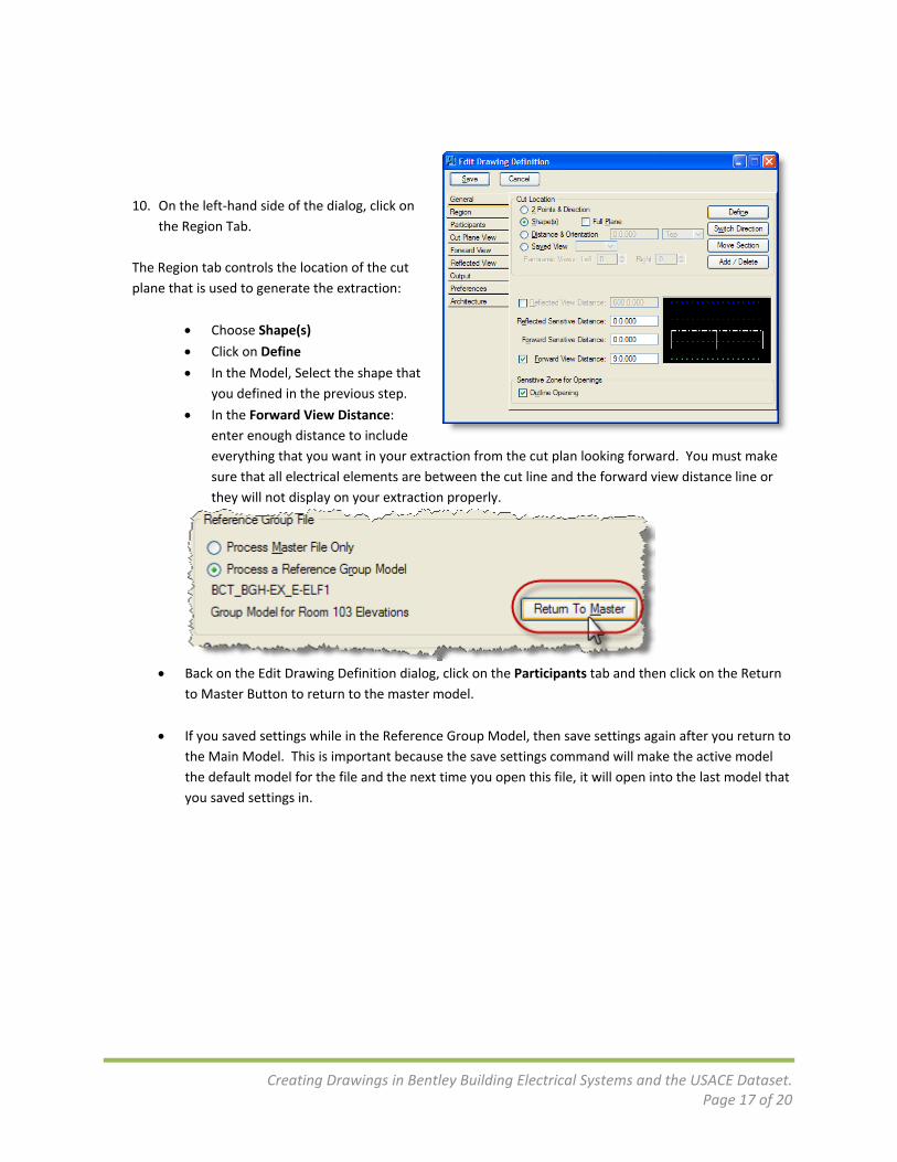
10. On the left‐hand side of the dialog, click on
the Region Tab. The Region tab controls the location of the cut plane that is used to generate the extraction:
• Choose Shape(s)
• Click on Define
• In the Model, Select the shape that you defined in the previous step.
• In the Forward View Distance: enter enough distance to include everything that you want in your extraction from the cut plan looking forward. You must make sure that all electrical elements are between the cut line and the forward view distance line or they will not display on your extraction properly.
• Back on the Edit Drawing Definition dialog, click on the Participants tab and then click on the Return
to Master Button to return to the master model.
• If you saved settings while in the Reference Group Model, then save settings again after you return to the Main Model. This is important because the save settings command will make the active model the default model for the file and the next time you open this file, it will open into the last model that you saved settings in.

Creating Drawings in Bentley Building Electrical Systems and the USACE Dataset. Page 18 of 20
11. Click on the Cut Plane View tab.
• Since we placed the cut plane above all of the symbols in our model, there are no symbols being cut so this tab is not important.
12. Click on the Forward View tab.
• The critical thing on this tab is the Compound Cell Plan Symbols check box. This will tell the extraction to only display the 2D part of compound cells. Since all of the symbols that we placed in our models are compound cells, this is very important.
13. Click on the Reflected View tab.
• This tab is only used by the Architects to generate their reflected ceiling plans. We will not be using it in Electrical extractions.

Creating Drawings in Bentley Building Electrical Systems and the USACE Dataset. Page 19 of 20
14. Click on the Output Tab: • The settings on this tab are set
for you in the template you selected earlier.
15. Click on the Preferences Tab: • On this tab, it is important that
Never Hide Text / Spaces is turned on if you are using a filled font(like Arial) for your subtype and circuit number labels. If this is not on, the filled fonts will be drawn as outlines.
16. Click on the Architecture Tab: • This tab contains settings only for the
Architects and is not used in BBES.

Creating Drawings in Bentley Building Electrical Systems and the USACE Dataset. Page 20 of 20
17. On the upper left‐hand corner of the Edit Drawing Definition dialog, click on Save.
18. Select your Extraction Definition in the Drawing Extraction Manager List and click on the Calculate All
button in the upper right‐hand corner of the dialog. (It looks like a pencil on a drafting board.)
19. Your drawing will now be created and saved into the extractions folder
for your discipline. A preview of the drawing will open in View 8. You can open the Drawing by clicking on the Open button. (It looks like an opening folder.)