building object-oriented software with the d-bus messaging system
TRANSCRIPT
Building object-oriented software with the D-Busmessaging system
UNIVERSITY OF TURKUDepartment of Information Technology
Computer ScienceMaster of Science Thesis
June 18, 2012Olli Salli

UNIVERSITY OF TURKUDepartment of Information Technology
SALLI, OLLI: Building object-oriented software with the D-Bus messaging sys-tem
Master’s Thesis, 100 p.Computer ScienceJune 2012
Object-oriented programming is a widely adopted paradigm for desktop software devel-opment. This paradigm partitions software into separate entities, objects, which consistof data and related procedures used to modify and inspect it. The paradigm has evolvedduring the last few decades to emphasize decoupling between object implementations, viameans such as explicit interface inheritance and event-based implicit invocation.
Inter-process communication (IPC) technologies allow applications to interact with eachother. This enables making software distributed across multiple processes, resulting in amodular architecture with benefits in resource sharing, robustness, code reuse and secu-rity. The support for object-oriented programming concepts varies between IPC systems.This thesis is focused on the D-Bus system, which has recently gained a lot of users, butis still scantily researched. D-Bus has support for asynchronous remote procedure callswith return values and a content-based publish/subscribe event delivery mechanism.
In this thesis, several patterns for method invocation in D-Bus and similar systems arecompared. The patterns that simulate synchronous local calls are shown to be danger-ous. Later, we present a state-caching proxy construct, which avoids the complexity ofproperly asynchronous calls for object inspection. The proxy and certain supplementaryconstructs are presented conceptually as generic object-oriented design patterns. Theeffect of these patterns on non-functional qualities of software, such as complexity, per-formance and power consumption, is reasoned about based on the properties of the D-Bussystem. The use of the patterns reduces complexity, but maintains the other qualities at agood level.
Finally, we present currently existing means of specifying D-Bus object interfaces for thepurposes of code and documentation generation. The interface description language usedby the Telepathy modular IM/VoIP framework is found to be an useful extension of thebasic D-Bus introspection format.
Keywords: D-Bus, proxy object, design patterns, interface description language, inter-process communication, object-oriented, Telepathy

TURUN YLIOPISTOInformaatioteknologian laitos
SALLI, OLLI: Oliopohjaisten ohjelmistojen rakentaminen D-Bus-viestintäjärjes-telmää käyttäen
Pro gradu -tutkielma, 100 s.TietojenkäsittelytiedeKesäkuu 2012
Oliopohjainen ohjelmointi on laajasti käytetty menetelmä työpöytäohjelmistojen toteutta-miseen. Tässä menetelmässä ohjelmisto jakautuu erillisiin osiin, olioihin, jotka koostuvattiedosta ja siihen liittyvästä toiminnallisuudesta, jota käytetään tiedon muokkaamiseen jatarkasteluun. Menetelmä on kehittynyt viimeisten vuosikymmenten aikana painottamaanolioiden toteutusten erottamista toisistaan, tavoilla kuten rajapinnoista periminen ja ta-pahtumapohjainen implisiittinen kutsuminen.
Prosessienvälisen kommunikaation (IPC) menetelmät mahdollistavat sovellusten kommu-nikoinnin toistensa kanssa. Tämän ansiosta ohjelmistot voidaan hajauttaa useaan proses-siin, jolloin syntyy modulaarinen arkkitehtuuri, mistä on hyötyä resurssien jakamiselle,selviytymiskyvylle, toteutuksen uudelleenkäytölle ja turvallisuudelle. Tuki oliopohjaisenohjelmoinnin periaatteille vaihtelee IPC-järjestelmien välillä. Tässä opinnäytteessä keski-tytään D-Bus-järjestelmään, joka on viime aikoina saanut paljon käyttäjiä, mutta on yhävahäisesti tutkittu. D-Bus-järjestelmässä on tuki asynkronisille etäproseduurikutsuille pa-luuarvoin ja sisältöpohjainen julkaisija/tilaaja-tyyppinen tapahtumienvälitysmekanismi.
Opinnäytteessä vertaillaan muutamia malleja metodien kutsumiseen D-Busissa ja saman-kaltaisissa järjestelmissä. Synkronisia paikallisia kutsuja matkivien mallien näytetään ole-van vaarallisia. Myöhemmin esitellään tilaa peilaava edustajaoliorakenne, joka kiertääaitojen asynkronisten kutsujen monimutkaisuuden olioiden tarkastelussa. Edustajaolio jaeräät täydentävät rakenteet esitetään käsitteellisesti yleisinä oliopohjaisina suunnittelu-malleina. Näiden mallien vaikutusta ohjelmistojen ei-toiminnallisiin ominaisuuksiin, ku-ten monimutkaisuuteen, suorituskykyyn ja virrankulutukseen, arvioidaan D-Bus-järjestel-män ominaisuuksiin perustuen. Mallien käyttäminen vähentää monimutkaisuutta, muttasäilyttää muut ominaisuudet hyvällä tasolla.
Lopuksi tarkastellaan olemassa olevia menetelmiä D-Bus-oliorajapintojen määrittelyynohjelmakoodin ja dokumentaation generointia varten. Modulaarisen Telepathy-viestintä-ohjelmakehyksen käyttämä rajapintojen määrittelykieli havaitaan hyödylliseksi laajen-nokseksi D-Bus-introspektiomuotoon nähden.
Asiasanat: D-Bus, edustajaolio, suunnittelumallit, rajapintojen määrittelykieli, prosessi-envälinen kommunikointi, oliopohjaisuus, Telepathy

Contents
List of Figures iii
List of Tables iv
List of Symbols v
1 INTRODUCTION 11.1 Problem Definition . . . . . . . . . . . . . . . . . . . . . . . . . . . . . 21.2 Project Organization . . . . . . . . . . . . . . . . . . . . . . . . . . . . 31.3 Report Structure . . . . . . . . . . . . . . . . . . . . . . . . . . . . . . . 4
2 OBJECT-ORIENTED PROGRAMMING 52.1 Abstraction . . . . . . . . . . . . . . . . . . . . . . . . . . . . . . . . . 52.2 Inheritance . . . . . . . . . . . . . . . . . . . . . . . . . . . . . . . . . . 7
2.2.1 Implications on typing . . . . . . . . . . . . . . . . . . . . . . . 102.3 Delegation . . . . . . . . . . . . . . . . . . . . . . . . . . . . . . . . . . 102.4 Explicit Interfaces . . . . . . . . . . . . . . . . . . . . . . . . . . . . . . 122.5 Design by Contract . . . . . . . . . . . . . . . . . . . . . . . . . . . . . 152.6 Exceptions . . . . . . . . . . . . . . . . . . . . . . . . . . . . . . . . . . 172.7 Events . . . . . . . . . . . . . . . . . . . . . . . . . . . . . . . . . . . . 19
3 INTER-PROCESS COMMUNICATION 233.1 Remote Procedure Calls . . . . . . . . . . . . . . . . . . . . . . . . . . . 26
3.1.1 Asynchrony and return values . . . . . . . . . . . . . . . . . . . 283.2 Proxies . . . . . . . . . . . . . . . . . . . . . . . . . . . . . . . . . . . . 31
3.2.1 Proxy-principal communication protocol . . . . . . . . . . . . . . 343.3 The Publish/Subscribe Paradigm . . . . . . . . . . . . . . . . . . . . . . 353.4 D-Bus . . . . . . . . . . . . . . . . . . . . . . . . . . . . . . . . . . . . 39
3.4.1 Object model . . . . . . . . . . . . . . . . . . . . . . . . . . . . 403.4.2 Message format . . . . . . . . . . . . . . . . . . . . . . . . . . . 423.4.3 The bus daemon . . . . . . . . . . . . . . . . . . . . . . . . . . . 463.4.4 The Properties interface . . . . . . . . . . . . . . . . . . . . . . . 493.4.5 The ObjectManager interface . . . . . . . . . . . . . . . . . . . . 51
3.5 Correctness and Scalability Constraints . . . . . . . . . . . . . . . . . . . 523.5.1 Message ordering . . . . . . . . . . . . . . . . . . . . . . . . . . 533.5.2 Asynchronous method calls . . . . . . . . . . . . . . . . . . . . . 543.5.3 Message granularity . . . . . . . . . . . . . . . . . . . . . . . . . 58

4 METHODOLOGY 604.1 Describing Design Patterns . . . . . . . . . . . . . . . . . . . . . . . . . 604.2 Predicting Programming Complexity . . . . . . . . . . . . . . . . . . . . 62
5 DESIGNING D-BUS CLIENT APPLICATIONS 655.1 Pending Operation Objects . . . . . . . . . . . . . . . . . . . . . . . . . 665.2 State Caching . . . . . . . . . . . . . . . . . . . . . . . . . . . . . . . . 705.3 Opt-in to Avoid Unnecessary Wakeups . . . . . . . . . . . . . . . . . . . 745.4 Asynchronous Proxy Factories . . . . . . . . . . . . . . . . . . . . . . . 785.5 Multiplexed State Synchronization . . . . . . . . . . . . . . . . . . . . . 80
6 AUTOMATED D-BUS PROXY GENERATION 856.1 Procedural Interface Description . . . . . . . . . . . . . . . . . . . . . . 866.2 The Telepathy Interface Description Format . . . . . . . . . . . . . . . . 87
6.2.1 Integer and string constants . . . . . . . . . . . . . . . . . . . . . 876.2.2 Complex types . . . . . . . . . . . . . . . . . . . . . . . . . . . 896.2.3 Miscellaneous features . . . . . . . . . . . . . . . . . . . . . . . 90
7 CONCLUSION 92
References 94

List of Figures
2.1 Recursive decomposition of a problem . . . . . . . . . . . . . . . . . . . 62.2 Objects and classes . . . . . . . . . . . . . . . . . . . . . . . . . . . . . 62.3 The decoupling provided by the constructor . . . . . . . . . . . . . . . . 82.4 Specializing classes through inheritance . . . . . . . . . . . . . . . . . . 92.5 Example of multiple inheritance . . . . . . . . . . . . . . . . . . . . . . 92.6 Delegating to an object based on a runtime reference . . . . . . . . . . . 112.7 Delegating to an ancestor class . . . . . . . . . . . . . . . . . . . . . . . 112.8 Accessing an object through an interface reference . . . . . . . . . . . . . 132.9 Implementing an interface using a helper object . . . . . . . . . . . . . . 152.10 The class invariant and method contracts . . . . . . . . . . . . . . . . . . 172.11 Example of a class invariant being temporarily broken . . . . . . . . . . . 192.12 Connections between events and handlers . . . . . . . . . . . . . . . . . 202.13 Example of role-based distribution of events across interfaces . . . . . . . 22
3.1 Nodes, processes and threads in a distributed system . . . . . . . . . . . . 233.2 Code and data in a shared memory area . . . . . . . . . . . . . . . . . . 243.3 Distribution of privilege requirements over a modular application . . . . . 253.4 Client and service stubs in an RPC system . . . . . . . . . . . . . . . . . 273.5 Sharing the argument stack between processes . . . . . . . . . . . . . . . 283.6 Ambiguity of service state after a communication failure . . . . . . . . . 293.7 Using threads to continue local execution during RPC . . . . . . . . . . . 303.8 RPC with promise objects . . . . . . . . . . . . . . . . . . . . . . . . . . 313.9 Shapiro’s proxy pattern . . . . . . . . . . . . . . . . . . . . . . . . . . . 323.10 Operation of a proxy object with a local state copy . . . . . . . . . . . . . 333.11 Representing an returned service object with a proxy . . . . . . . . . . . 343.12 Adaptor objects in a proxy-based IPC system . . . . . . . . . . . . . . . 353.13 The publish/subscribe paradigm . . . . . . . . . . . . . . . . . . . . . . 363.14 Distributed publish/subscribe architecture . . . . . . . . . . . . . . . . . 383.15 Publish/subscribe communication using a central messaging service . . . 393.16 The function of the reply_serial field in D-Bus . . . . . . . . . . . . . 443.17 D-Bus bus topology . . . . . . . . . . . . . . . . . . . . . . . . . . . . . 463.18 Layout of the GetManagedObjects return value . . . . . . . . . . . . . 523.19 Reordering of a kick event and a method call . . . . . . . . . . . . . . . . 543.20 Simultaneous method call between two processes . . . . . . . . . . . . . 563.21 Context switches during D-Bus message delivery . . . . . . . . . . . . . 59
iii

4.1 Structure of the Abstract Factory pattern . . . . . . . . . . . . . . . . . . 62
5.1 Structure of the Pending Operation Objects pattern . . . . . . . . . . . . 685.2 Structure of the Composite Pending Operation pattern . . . . . . . . . . . 705.3 Life cycle of a Connection proxy . . . . . . . . . . . . . . . . . . . . . . 735.4 Structure of the State Caching Proxy pattern . . . . . . . . . . . . . . . . 755.5 Structure of the Optional Proxy Features pattern . . . . . . . . . . . . . . 775.6 Structure of the Asynchronous Proxy Factory pattern . . . . . . . . . . . 815.7 Contact ownership in Telepathy . . . . . . . . . . . . . . . . . . . . . . . 825.8 Structure of the Multiplexed State Synchronization pattern . . . . . . . . 83
6.1 Layering of proxies in Telepathy client libraries . . . . . . . . . . . . . . 856.2 Layout of the first argument of the ContactsChanged signal . . . . . . . 88
List of Tables
3.1 D-Bus basic types . . . . . . . . . . . . . . . . . . . . . . . . . . . . . . 423.2 Some semantics of D-Bus match rules . . . . . . . . . . . . . . . . . . . 48
iv

List of Symbols
APM Arguments per member . . . . . . . . . . . . . . . . . . . . . . . . . . 63Cc Constraint complexity . . . . . . . . . . . . . . . . . . . . . . . . . . . 62Cg Configuration complexity . . . . . . . . . . . . . . . . . . . . . . . . . 62Cs Signature complexity . . . . . . . . . . . . . . . . . . . . . . . . . . . 62IC Interface complexity . . . . . . . . . . . . . . . . . . . . . . . . . . . 62ne Number of events in the interface . . . . . . . . . . . . . . . . . . . . . 63no Number of operations in the interface . . . . . . . . . . . . . . . . . . 63CPU Central processing unit . . . . . . . . . . . . . . . . . . . . . . . . . . 29GUI Graphical user interface . . . . . . . . . . . . . . . . . . . . . . . . . . 55IDL Interface description language . . . . . . . . . . . . . . . . . . . . . . 35IM Instant messaging . . . . . . . . . . . . . . . . . . . . . . . . . . . . . . 2IPC Inter-process communication . . . . . . . . . . . . . . . . . . . . . . . . 1ISP Interface segregation principle . . . . . . . . . . . . . . . . . . . . . . 21NAT Network address translation . . . . . . . . . . . . . . . . . . . . . . . . 26RPC Remote procedure call . . . . . . . . . . . . . . . . . . . . . . . . . . 26UI User interface . . . . . . . . . . . . . . . . . . . . . . . . . . . . . . . 76UML2 Unified Modeling Language version 2 . . . . . . . . . . . . . . . . . . 60
v
1 INTRODUCTION
Computer desktop environments have traditionally been seen as collections of applica-tions that are implemented using a common infrastructure. However, the applications arejust means to an end—they are utilized by users to achieve the goals in their personal use
cases for the system. A single application can seldom offer all the functionality requiredfor a particular use case without becoming excessively complicated to use for others. Fur-thermore, large monolithic applications end up duplicating a lot of their implementationwith other applications with overlapping functionality. Thus, it is beneficial to combinesmaller software components together, so that they can be used to perform a real-worldtask.
Software libraries allow factoring out common parts of application implementationsto modules that are shared between multiple applications. Libraries consist of constructssuch as methods, object-oriented classes, and data. For example, the visual representationcode of the lower-level graphical user interface components such as buttons and forms canbe shared by the applications in a desktop environment. Such reusable elements are typ-ically implemented as object-oriented classes. In general, object-oriented programminghas been widely adopted in desktop application development due to the possibilities itoffers for creating intuitive analogues of real-world entities.
Inter-process communication (IPC) technologies, such as CORBA, DCOP, and D-Bus, allow applications to interact with each other. Such interaction allows delegating
parts of the tasks that an application is required to perform to other applications, whichact as services. Some desktop service applications might be stand-alone backends, withno directly accessible user interface. Multiple user-visible frontend processes can accessa single backend concurrently.
Both utilizing software libraries and delegating duties to backends via IPC help avoidduplication of implementation effort in applications. However, while applications em-ploying a library’s services end up duplicating its runtime state, a single backend’s stateand the results it produces can be consumed by any number of frontend consumers si-multaneously, conserving resources. This is especially important in processing power,working memory and electrical energy constrained environments, such as those presentin the emerging smart phone and mobile internet device fields.
Some resources cannot be concurrently accessed by multiple applications. A backendcan be used to expose such a resource as a service, governing access to it. As a practicalexample, many online real-time communications services, such as Windows Live Mes-senger, only allow one connection to be made to a user account at a time. Unless thisconnection is shared via a backend process that serves as an intermediary, only a single
1

application can communicate through the online service simultaneously. Such online ser-vices however offer functionality related to multiple different use cases, such as voice andvideo calling, file transfer and sharing media such as images, in addition to textual conver-sations. Incorporating all that functionality to a single application, as would be necessaryunless a frontend-backend model is utilized, would require a very large and complicateduser interface and would be a significant implementation and maintenance burden.
Thus, refactoring traditional monolithic applications to a multitude of frontend andbackend processes, connected using IPC, can enable a more task-oriented division ofdesktop functionality. Continuing the instant messaging example, a minimal taskbar ap-plet application could be constantly running to show and allow changing the user’s onlinestatus in the network. Another purpose-built application could be used to view the listof contacts reachable through the account, and a yet separate one would launch to han-dle a call placed on one of them. All three applications could share a single networkconnection to the messaging network, maintained by a backend. The Telepathy frame-work [dTdCDG+12] is a practical generalized implementation of online real-time com-munication functionality, such as instant messaging (IM), built around the D-Bus IPCsystem.
While IPC enables new kinds of application interaction patterns, its use also gives riseto many challenges that are not present in the design of monolithic applications. Invokingremote methods and especially transferring the results back carries a significant perfor-
mance overhead compared to calling code in the local process. Concurrent programming
pitfalls, such as the possibility for deadlocks and race conditions, also apply because thefrontend and backend processes run independently. Overcoming these drawbacks canincrease programming complexity.
Whereas a service backend encompassing a given set of functionality is usually imple-mented just once, the challenges in accessing it via IPC are present in all of its frontends.Suitable IPC protocol and service access interface design enables providing service-specificclient libraries that ease this burden and hence further the use of desktop services. A clientlibrary is a software library specifically created to offer a more natural interface to accessbackend services. Ideally, they could make remote objects as simple to use programmati-cally as local ones, while handling the IPC communication behind the scenes in a correctand efficient fashion.
1.1 Problem Definition
There are multiple existing distributed software frameworks, built around various kindsof IPC systems to fulfill desktop use cases. This report attempts to define the most ad-
2
vantageous IPC communication patterns for building such systems. The three mutuallyconflicting viewpoints of performance/scalability, correctness and programming conve-nience are considered.
The D-Bus IPC system has gained extensive practical adoption during the last fewyears, especially on Linux-based platforms. However, there is little academic researchavailable on the subject of this system. We will study the properties of D-Bus in thecontext of existing research on other IPC technologies.
As the widespread adoption of desktop services is more dependent on frontend thanbackend implementation convenience, a specific focus is given to design techniques forthe client libraries used by frontends to access the services. The goal is to identify andformalize object-oriented design patterns specifically related to inter-process object ac-cess. The design of the components of the Telepathy framework is used here as a sourceof ideas and examples.
Additionally, we explore methods to automate some parts of the implementation ofclient libraries. This is centered around a study of languages for specifying D-Bus inter-faces.
These focus areas of the research can be summarized as the following questions:
• How do IPC systems in general and D-Bus in particular support object-orientedprogramming?
• How should IPC messaging be designed to ensure reasonable performance and re-liability?
• Which kinds of design patterns are useful for building well-behaving object-orientedsoftware with the D-Bus system?
• How can the implementation effort of D-Bus communication be kept at a manage-able level?
1.2 Project Organization
This report has been authored by Olli Salli, in partial fulfillment of the requirementsfor the degree of Master of Science in Computer Science at the University of Turku.The research leverages work done for and is supported by Collabora Limited, a softwareconsultancy specializing in open source technologies and principles.
The work is supervised at the Department of Information Technology in the Universityof Turku by Professor, Ph.D. Olli Nevalainen. This final report has additionally beeninspected by Professor, Ph.D. Ville Leppänen.
3

1.3 Report Structure
Chapter 2
In Chapter 2 we present, through literary review, core object-oriented programming con-cepts, as relevant to our study of object-oriented systems in a distributed setting. Wealso make observations on certain challenges in the practical implementation of theseconcepts. These will be very relevant in the inter-process context.
Chapter 3
In this chapter, inter-process communication is explored. The support for generic object-oriented concepts in existing IPC systems is evaluated. There is a specific focus on theproperties of the D-Bus message bus system.
Chapter 4
Chapter 4 introduces the formal methods we will later use for describing implementa-tion patterns of object-oriented distributed software, and for evaluating their impact onsoftware complexity.
Chapter 5
In this chapter, we propose some architectural guidelines for the design of D-Bus clientsoftware. This is be centered around an extension to the proxy pattern of Shapiro [Sha86]for structuring distributed systems. We study implementing the extended proxy patternusing D-Bus facilities, and formally evaluate its impact on non-functional qualities ofresulting systems. Also, some other constructs directly related to the proxies are explored,as are implications on D-Bus interface design.
Chapter 6
In this chapter, we describe some methods to describe D-Bus interfaces in a machinereadable fashion. We present a sophisticated interface description language (IDL), fromwhich documentation and lower-level D-Bus client and service code can be automaticallygenerated.
Chapter 7
Here, we review key points of the research and summarize the findings.
4
2 OBJECT-ORIENTED PROGRAMMING
The object-oriented paradigm of programming partitions software into separate runtimeentities, objects, which consist of data and related procedures used to inspect and modifyit [Coh84]. Objects belong to one or more classes, which serve as templates for objectinstances (Section 2.1). The ability to extend classes via inheritance (Section 2.2) com-pletes the classical definition of an object-oriented language [Weg87]:
object-oriented = objects + classes + inheritance
Delegation (Section 2.3) can be thought of as a more dynamic form of inheritance.Inheriting from explicit interfaces (Section 2.4) and having events (Section 2.7) as objectinterface members are more recent refinements to the object-oriented paradigm. All threeof these concepts attempt to decrease coupling between object implementations. Thisdecoupling improves modularity and code reusability, as will be discussed later. Finally,the design by contract philosophy (Section 2.5) and exception handling (Section 2.6) dealwith corner-cases during the execution of object-oriented software.
Object-oriented programming is a very wide subject. Here, we just define the coreconcepts that are relevant to our analysis of object orientation in a distributed environ-ment. Additionally, the implementation of object oriented concepts varies highly betweenprogramming languages. We attempt to present them in a language neutral manner, butstill draw examples from certain archetypal languages. Our target application area of dis-tributed systems is not restricted to a single language either, even within a single system.We will study how principles and implementations of inter-process communication relateto these generic object-oriented concepts in Chapter 3.
2.1 Abstraction
In procedural programming, algorithmic solutions to problems are constructed from pro-
cedures. These smaller program fragments perform sub-tasks in a “black box” fashion.Input data is passed to procedures as parameters. The parameters are often constructedfrom results which have itself been produced by procedures invoked earlier [BBG+63].Recursive composition of ever higher level procedures leads to a complete solution to theoriginal problem, as illustrated in Figure 2.1. Thus, procedures act as functional abstrac-
tions [LZ74]—building blocks that solve a particular task without their user having toknow how exactly they do that.
The SIMULA 67 programming language introduced the concept of classes. Classesbundle together patterns of data and procedures operating on it (actions) [DMN68]. These
5

Prepare dinner
Procure ingredients Cook meals Serve to table
Select Pay
Figure 2.1: Recursive decomposition of a problem
collections of functionality can be used without manually transferring data between indi-vidual procedures. This makes them ideal as abstract reusable models of problem orientedconcepts, such as customers, shapes or bank accounts, as opposed to a bunch of unrelatedmemory locations (variables) and executable code.
Classes are not live instances of the entity they are modeling by itself, but instead actas static templates, cookie-cutters for an arbitrary number of objects which fill this role atruntime [Coh84]. Objects of a given class all share the set of functionality defined in theclass, but the internal data used by their member procedures is separate. This individual“memory” of objects is called their state [Weg87]. For example, there could be a Personclass, which models real-world people. One object of this class could carry a birth dateof 1948-05-12 as part of its state, while another one could simultaneously store the date1963-05-04. These objects are depicted in Figure 2.2 along with an object of anotherclass.
Classes
Objects
Person
+printBirthCertificate()
Circle
+paint()+moveTo(x, y)
Name
John Doe
Born
1948-05-12
is a
Name
Jane Doe
Born
1963-05-04
is a
Position
(-1, 3)
Radius
2
is a
Figure 2.2: Objects and classes
6

Object state is represented by member variables. The data members of SIMULA ob-jects can be directly accessed anywhere ([DMN67], Chapter 7). In fact, it’s possible tousefully declare pure data classes that contain no other actions than access [DMN68].Liskov and Zilles argued [LZ74] that the abstract semantics and available operationsshould define a data type, not the internal representation of its state. Accordingly, theprincipal difference between their concept of operation clusters and SIMULA classes isthat cluster state variables are only accessible within operation implementations. The stateis observed externally using inspection operations, which decouple the semantics of thedata from its representation. Hence clusters provide a form of data abstraction, unlikeSIMULA classes [Weg87]. The language used by Liskov and Zilles for their researchwas later named CLU, specifically after the cluster feature.
The use of the class keyword from SIMULA has been widely adopted in more re-cent object-oriented programming languages, such as C++. In many of these languages,outside access to object internals can be restricted [Sny86]. Thus, the classes of these lan-guages have the data abstraction capabilities of CLU clusters, unlike those of SIMULA.
The key feature introduced in CLU that enabled full data abstraction was the con-
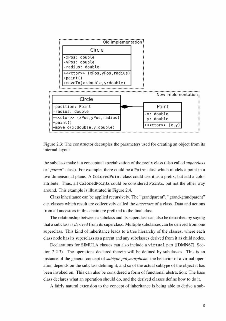
structor (called “create-code” in CLU). The constructor is a special class/cluster oper-ation which initializes the internal representation of an object when one is created. Itdecouples the layout of the object from the parameters, if any, required by it to generatethe values for the members. It is thus possible to change the internal representation ofobjects without breaking existing user code creating them, as long as the constructor caninitialize the new layout from the old parameters. In the example in Figure 2.3, the way ofstoring a geometrical object’s location could be changed from separate coordinate valuesto a Point class, while keeping the same external interface.
Simple operations which allow inspecting a particular aspect of an object’s state arecalled getters in programming parlance (e.g. [Hug02]). Liskov and Zilles identified theneed to perform calls to these small operations as a potential performance problem. Theirsolution was a compiler optimization, which replaces the calls with inlined code. Inliningmeans copying the operation implementation to the call site, such that function call over-head is avoided [LZ74]. However, as we will explain later, it is not very straightforwardto realize this optimization in an inter-process context.
2.2 Inheritance
SIMULA classes could already be used as “prefixes” in each other, such that a class wouldinherit all data and actions from the classes declared as its prefixes [DMN68]. A classthat inherits members from a prefix class is called a subclass. New members declared in
7
Circle-xPos: double-yPos: double-radius: double
+<<ctor>> (xPos,yPos,radius)+paint()+moveTo(x:double,y:double)
Point-x: double-y: double
+<<ctor>> (x,y)
Circle-position: Point-radius: double
+<<ctor>> (xPos,yPos,radius)+paint()+moveTo(x:double,y:double)
Old implementation
New implementation
Figure 2.3: The constructor decouples the parameters used for creating an object from itsinternal layout
the subclass make it a conceptual specialization of the prefix class (also called superclass
or “parent” class). For example, there could be a Point class which models a point in atwo-dimensional plane. A ColoredPoint class could use it as a prefix, but add a colorattribute. Thus, all ColoredPoints could be considered Points, but not the other wayaround. This example is illustrated in Figure 2.4.
Class inheritance can be applied recursively. The ”grandparent”, ”grand-grandparent”etc. classes which result are collectively called the ancestors of a class. Data and actionsfrom all ancestors in this chain are prefixed to the final class.
The relationship between a subclass and its superclass can also be described by sayingthat a subclass is derived from its superclass. Multiple subclasses can be derived from onesuperclass. This kind of inheritance leads to a tree hierarchy of the classes, where eachclass node has its superclass as a parent and any subclasses derived from it as child nodes.
Declarations for SIMULA classes can also include a virtual part ([DMN67], Sec-tion 2.2.3). The operations declared therein will be defined by subclasses. This is aninstance of the general concept of subtype polymorphism: the behavior of a virtual oper-ation depends on the subclass defining it, and so of the actual subtype of the object it hasbeen invoked on. This can also be considered a form of functional abstraction: The baseclass declares what an operation should do, and the derived classes define how to do it.
A fairly natural extension to the concept of inheritance is being able to derive a sub-
8

Point+x: double+y: double
ColoredPoint+x: double+y: double+color: Color
(2, 2) (0, 1, Red)(1, 1, Blue)
Figure 2.4: Specializing classes through inheritance
class from multiple superclasses simultaneously. This is called multiple inheritance. Incontrast with the previously presented concept of single inheritance, the classes in multi-ple inheritance schemes form a directed acyclic graph topology, as shown in Figure 2.5.Multiple inheritance complicates subtype polymorphism somewhat: As it is possible formultiple classes at the same level of the inheritance hierarchy to define a common opera-tion, there is ambiguity in which definition should be used [Sny86].
Car
Sedan Sport utility vehicle Station wagon
Crossover vehicle
Figure 2.5: Example of multiple inheritance
9
2.2.1 Implications on typing
Liskov and Zilles suggested [LZ74] that languages should treat mismatches between ac-tual and excepted types either as errors (strong typing) or through automated type conver-sions. This should happen for both built-in and user-defined (class) types. However, thecluster concept in their research language did not support any form of inheritance.
The introduction of inheritance complicates the notion of typing. What should happenwhen a derived type is used in a context which expects an object belonging to its parentclass? Such a situation might occur for example when an object reference is passed as aparameter to a function.
In many languages, using a subclass instance where one of its parent class is expectedis considered acceptable: In them, class inheritance directly establishes a subtyping rela-tionship. Snyder associates [Sny86] these semantics with a thinking where the purposeof inheritance is recursive definition of types by specializing the parent class. From thisperspective, the relationship between the parent and the derived class is a public commit-ment. Snyder further argues that it should be possible to use inheritance to facilitate code
sharing, without making such a constraining decision. This is called implementation in-
heritance. Changing a class used as an implementation helper is guaranteed to not breakexisting callers only if implementation inheritance is not visible in the external interfaceof classes [Wol92].
2.3 Delegation
Objects are the runtime instances of classes. The runtime state of objects can changeindependently from other instances of the same class. However, the set of operationswhich defines an object’s interface to its users is tied to what was declared in its own classand ancestor classes. In other words, the set of supported operations is static at runtime.Even more importantly, the specific virtual method definition to use for those operations isalso chosen based on the inheritance relationships established when writing the program.
Delegation [Lie86] is the act of an object operation implementation to transfer theresponsibility for its completion to some other object. The choice may be based on aruntime attribute, e.g. a reference to the object which is delegated to (the delegatee). Thisenables dynamic operation specialization, even for a single object instance, such as howinstances of the Car class delegate the act of starting up to different Engines in Figure 2.6.
Let us consider the parts of objects contributed to them by each ancestor class asseparate objects in their own right. Then, we can interpret class inheritance schemes asdefining a static delegation setup between these objects (e.g. Wolczko [Wol92]). When anoperation is invoked on an object of a derived class type, it uses the derived class imple-
10

Car-engine: Engine
+changeEngine(engine)+start()
Engine-serialNumber-mileage
+start()
delegates
RepairShop+spareEngines: Engine[]
calls
Figure 2.6: Delegating to an object based on a runtime reference
mentation, if there is one. Otherwise, it delegates to one of the part-objects correspondingto the ancestor classes. This is the case for the moveTo() operation in the example in Fig-ure 2.7. This operation is the same for regular and colored points, so colored points usethe implementation from their superclass. We can conclude that the concept of delegationis at least as general as that of class inheritance.
Point-x: double-y: double
+moveTo(x,y)+paint()
ColoredPoint-x: double-y: double-color: Color
+moveTo(x,y)+paint()
delegates
Specialized implementation
Figure 2.7: Delegating to an ancestor class
Central to the delegation pattern is an assumption that the delegated-to objects willoften need to query the object delegating to them (the client) for additional details requiredfor completing the task. Lieberman [Lie86] gives an example of a turtle delegating theresponsibility for drawing itself to a pen. The pen must query the the turtle for its position
11

to determine where to draw.Wolczko [Wol92] demonstrates this side of delegation with an analogy of a manager
giving a task to his or her subordinates. The subordinates consult the manager for de-tails as required. It could be theoretically possible for the manager to specify all thedetails along with giving the task. However, this would imply specifying more detailsthan needed for any given subordinate, as different employees will need different detailsto supplement their own knowledge. Only if the manager had perfect knowledge of thebackground of each employee, could he pass on just the relevant hints. But then the sub-ordinates would not be treated uniformly any longer: there would be increased couplingbetween the manager and the subordinates.
Accordingly, it is a key feature for systems where general delegation is important toprovide a mechanism for a delegatee to be able to query arbitrary additional informationfrom their client [Weg87]. One such mechanism is rebinding self, which makes the del-egatee dynamically able to refer to attributes of the current client object like they wereits own. Wolczko notes [Wol92] that this is similar to how operations defined in parentclasses can access attributes that might be redefined by the subclasses. However, becausethat is based on the static inheritance relationship, it is less flexible than dynamic rebind-ing to an arbitrary client.
With any mechanism for querying additional information from the client, it is neces-sary for the client to be able to respond to the query, although it is at the same time waitingfor the delegatee to finish the operation. A deadlock would otherwise occur [Lie86]. Thisobservation will be very important for us later in Section 3.5.2, where we define certainconstraints for the messaging patterns used for communication between objects in differ-ent processes.
2.4 Explicit Interfaces
If class inheritance is used just for implementation code-sharing, superclasses should notbe visible to the users of a subclass. This however implies that the public operations of thesuperclass must not be available either. Hence polymorphic behavior through a superclassreference is not attained.
The problem with inheriting both externally visible interface attributes and implemen-tation from a superclass is that these two components are tied together. When derivingfrom a superclass to gain an interface compatible with its clients, one will also restrictthemself to the overall implementation pattern of the superclass. On the other hand, wheninheritance is used to reuse implementation, one will have to continue using that particularimplementation helper class forever. Otherwise, compatibility will be lost with any users
12
that depend on the parts of the external interface contributed by that class. Whatever themotivation for using inheritance is, unless the classes involved are very minimal, someflexibility has been sacrificed unnecessarily.
This flexibility can be regained by decoupling the implementation and external inter-face aspects of inheritance from each other. Recall that the external interface of a class isdefined by the operations it supports. An explicit interface is a named collection of opera-tion declarations without any associated implementations. By implementing the memberoperations of an explicit interface, a class can provide an interface for external accesswithout placing any constraints on the internal implementation [CCHO89].
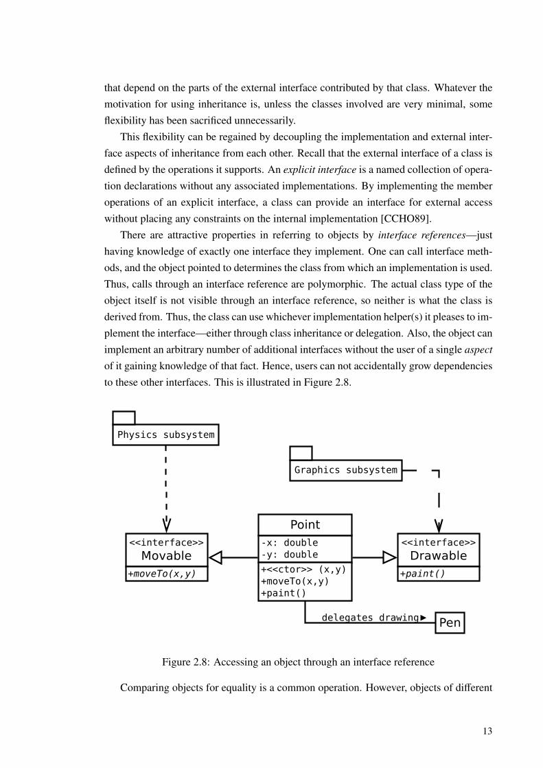
There are attractive properties in referring to objects by interface references—justhaving knowledge of exactly one interface they implement. One can call interface meth-ods, and the object pointed to determines the class from which an implementation is used.Thus, calls through an interface reference are polymorphic. The actual class type of theobject itself is not visible through an interface reference, so neither is what the class isderived from. Thus, the class can use whichever implementation helper(s) it pleases to im-plement the interface—either through class inheritance or delegation. Also, the object canimplement an arbitrary number of additional interfaces without the user of a single aspect
of it gaining knowledge of that fact. Hence, users can not accidentally grow dependenciesto these other interfaces. This is illustrated in Figure 2.8.
Point-x: double-y: double
+<<ctor>> (x,y)+moveTo(x,y)+paint()
<<interface>>
Movable+moveTo(x,y)
<<interface>>
Drawable+paint()
Physics subsystem
Graphics subsystem
Pendelegates drawing
Figure 2.8: Accessing an object through an interface reference
Comparing objects for equality is a common operation. However, objects of different
13
types can not be sensibly compared, even if they are derived from the same superclass.This is because specialized subclasses have additional information, which must be con-sidered for a full comparison, but is not present in instances of “sibling” subclasses or theparent class [CHC90]. For example, the intuitive definition of equality for two objectsof the Point class of Figure 2.4 from Section 2.2 is that their coordinate values match.However, is the blue ColoredPoint at (1, 1) equal to a non-colored Point at the samelocation? This is an excellent example of how such a fundamental and widely applicableoperation can cause conceptual issues if included, via inheritance, in the external interfaceof a subclass. One should not pollute interfaces that are intended to be generic with suchambiguous operations.
Interface pollution is actually an even more general issue. Objects are typically usedby more than one kind of a client. The variety in clients naturally leads to differingrequirements on the operations supported by the object. Let us consider one kind ofclient, which is intended to use a certain subset of the object’s public interface. If theinterface visible to the client exposes aspects of the object interface outside that subset,the client might start accidentally depending on properties which are not really relevantto it. This danger constrains changes to these parts of the object, even if their actuallyintended users could cooperate in going through some needed modification. From thispoint of view, parts of the interface beyond the subset intended to be used by a givenclient are pollution. This leads to the Interface segregation principle [Mar96], whichstates that there should be a separate explicit interface for each kind of a client. Turningthe relationship around, there should be an interface corresponding to each role the classis supposed to “act in” for its clients.
In the manager and subordinate example of the previous section, the manager had arole of answering queries from subordinates who need additional information. He willlikely also have a separate role in which he has to report the progress of tasks to his ownsuperiors. These could be formulated as a task detail query and as a task status reportinginterface, respectively. This increases flexibility: If the manager started using some kindof automated reporting software, he could pass on a reference to the reporting interfaceimplemented in this software system to his superiors instead of having to respond to reportqueries directly himself. Thanks to the explicit reporting interface, he can do this safely.There are no worries that the superiors might have accidentally carried away to snoopingaround task details. This info would not be available through the software their reference(say, an email address) now points to, but only to subordinates. This isolation scheme isshown in Figure 2.9.
The reporting software used by the manager is a good example of an additional con-struct closely related to interfaces. Whereas interfaces are collections of operation dec-
14

Legend:
Senior management
Progress reporting
Reporting software Project manager
Object
gives reporting reference
Task details
Subordinate
assigns tasks
Interface
Figure 2.9: The possibility of implementing an interface transparently using a helperobject
larations, mixin classes [BC90] are bunches of definitions for functionality. As the nameimplies, their functionality is intended to be “mixed in” via multiple inheritance or dele-gation to produce composite objects. Mixing in to an arbitrary object is only possible ifthe definition of a mixin class does not depend on knowledge of the other classes mixedin with it. This requirement is very similar to the flexibility rationale behind the interfaceconcept. If there is a sufficiently close mapping between external explicit interfaces aclass is required to implement and the mixin classes available to it, the class can use themixins as swappable implementation helpers for the interfaces (e.g. [Ber00]).
2.5 Design by Contract
The practice of defensive programming advocates guarding all operation implementa-tions against misuse and promises broken by the operations they themselves invoke. Thisis to be done by explicitly checking that all assumptions made by the code hold true.This leads to callers checking that everything is in an allowed state for calling a method,
15
and the called methods itself checking that the caller did this preparatory work. Meyerargues [Mey92] that these checks are mutually redundant, and hence add unneeded com-plexity. This makes the checks counterproductive—their purpose is to increase reliability,but according to him, that has an inverse correlation with complexity.
To remove the intrinsic redundancy from defensive programming, while retaining itsbenefits on special case survivability, Meyer proposes a division of the checking effort.Methods must document all of the conditions that must hold true to make them usable(preconditions), and the additional properties they make true when successfully calledin a suitable state (postconditions). Before calling an operation, a caller ensures thatall of the preconditions hold true. Then, the called operation can safely assume that thepreconditions are fulfilled, without explicitly checking for them. Similarly, the caller doesnot need to check that the operation did what it was supposed to, because this is guaranteedby its postconditions. Meyer relates this mutually beneficial agreement with real-worldcontracts between clients and suppliers. As a consequence, this design ideology is calleddesign by contract.
In Section 2.1, we introduced the constructor, a special class operation responsiblefor initializing the member variables of a created object. Thus, a postcondition of theconstructor is that the internal state of the object is consistent. The consistency relationsestablished by the constructor are collectively called the class invariant [Web01].
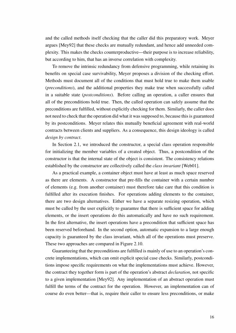
As a practical example, a container object must have at least as much space reservedas there are elements. A constructor that pre-fills the container with a certain numberof elements (e.g. from another container) must therefore take care that this condition isfulfilled after its execution finishes. For operations adding elements to the container,there are two design alternatives. Either we have a separate resizing operation, whichmust be called by the user explicitly to guarantee that there is sufficient space for addingelements, or the insert operations do this automatically and have no such requirement.In the first alternative, the insert operations have a precondition that sufficient space hasbeen reserved beforehand. In the second option, automatic expansion to a large enoughcapacity is guaranteed by the class invariant, which all of the operations must preserve.These two approaches are compared in Figure 2.10.
Guaranteeing that the preconditions are fulfilled is mainly of use to an operation’s con-crete implementations, which can omit explicit special case checks. Similarly, postcondi-tions impose specific requirements on what the implementations must achieve. However,the contract they together form is part of the operation’s abstract declaration, not specificto a given implementation [Mey92]. Any implementation of an abstract operation mustfulfill the terms of the contract for the operation. However, an implementation can ofcourse do even better—that is, require their caller to ensure less preconditions, or make
16
ManualResizeContainerinvariant: always space for
at least the number ofelements in the container
+<<constructor>> (elements)postcondition: space for thegiven elements
+reserveSpace(numElements)postcondition: space for thegiven amount of elements
+addElement(element)precondition: enough spacehas been reserved previously
AutoResizeContainerinvariant: always space forat least one more elementthan there are currently
stored
+<<constructor>> (elements)postcondition: space for thegiven elements and at leastone more
+addElement(element)postcondition: still spacefor more elements
Figure 2.10: The class invariant and method contracts
more postconditions hold than required. Meyer makes this observation in the context ofoverriding superclass method implementations. However, it is equally applicable to ex-plicit interfaces, as operations are declared in them with the same level of detail as inconcrete superclasses. Thus, the contracts established by an explicit interface must befollowed by all objects implementing it. Otherwise, users of the interface would need toseparately consider the requirements (preconditions) imposed by each possible implemen-tation. If this was required, the flexibility offered by the decoupling the external interfacefrom its concrete implementation would be lost.
2.6 Exceptions
It is not always possible for a method implementation to fulfill its contract, such that eventhough its preconditions have been satisfied, the postcondition can not be achieved. Thisis because the preconditions can never be truly exhaustive. For example, a finite globalresource, such as working memory, might be depleted between invoking an operation andthe operation trying to allocate some of the resource for use. Also, regarding this specificexample, very few systems provide any means for a caller to check for sufficient availableworking memory in the first place. When a procedure encounters a force majeure eventlike this, it must somehow tell its client that it failed.
17

There are a few possibilities for reporting errors to the user of an operation. A sim-ple approach is to extend the result domain of the operation with additional values thatindicate failure cases. As an example, consider a function that returns the square of areal number (x 7→ x2, x ∈ R). The result of this operation is non-negative for all x ∈ R.If a real number type which can represent both positive and negative values is used forthe return value of this function, negative values can be returned to indicate errors in thecalculation, such as arithmetic overflow. This approach is however problematic, first, be-cause for some operations the entire range of values representable by the return type areneeded for actual results. And second, because in this approach essentially the same event(e.g. memory exhaustion) has to be represented in different ways by operations with dis-similar result domains. Additionally, there is a danger of the client interpreting the errorcode as a normal result, or ignoring the result completely.
A better way to signal errors, provided the programming environment supports it, isto raise an exception [Goo75]. An exception is a uniform way to indicate that a particularerroneous circumstance has been encountered, no matter what the result domain of theoperation is. Furthermore, the programming environment can enforce the calling functionto take some action when an exception is raised, or failing that, perform a default actionsuch as program termination. The rationale for handling the exceptions in the callers ofthe operation which encountered the error is that it they have the best knowledge of the bigpicture. This knowledge can be used to gracefully recover from the error, or consciouslyignore it.
Goodenough’s example [Goo75] of an error which should be handled differently de-pending on the high-level context concerns an input stream, perhaps one that reads datafrom a file. For a byte-by-byte read operation on the stream, encountering the end-of-fileposition is a critical error. However, for a higher level procedure, the purpose of which isto read a file in its entirety to memory, this event would simply be an indication that itstask is finished. This is different for an operation that reads multi-byte records using thesame byte read operation. For it, only managing to read half of the bytes that are neededfor a complete record before the error occurs would be a failure.
So, external circumstances might prevent an operation from finishing successfullyeven if its formal preconditions were fulfilled. But what if they were not fulfilled in thefirst place? Meyer notes [Mey92] that in a single-threaded, local process context, this isalways a programming error, because the client has failed to keep its side of the contract.However, he also observes that this is different when multiple threads access an objectconcurrently. Then, a caller might have properly ensured that a precondition holds true,but a parallel thread may cause it to turn false again by the time the invoked operationdepends on it.
18
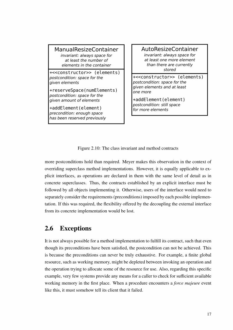
Another kind of class invariant violation might occur because of the fact that opera-tions are usually sequences of multiple subtasks. Class invariants may be broken by thefirst steps, as long as they are re-established later, before the method finishes executing.Thus, a parallel or re-entrant invocation of one of the object’s operations between thesesteps might find that the class invariant is not satisfied [Web01]. An example of this is de-picted in Figure 2.11. We will compare a few patterns of inter-process method invocationconsidering these aspects in Section 3.5.2. For now, it suffices to observe that in the pres-ence of multiple concurrent callers, the fulfillment of preconditions and class invariants isnot a given. Thus, gracefully handleable run-time exceptions are needed to communicatewhen they have been violated.
Bank account
Customer
balance: Integerdeposits: List
withdrawals: List
Invariant:balance =
deposits.sum -withdrawals.sum
withdraw(amount):
assert(amount <= balance)
withdrawals.append(amount)
client.chargeServiceFee(1)
balance -= amount
return amount
chargeServiceFee(amount):
while (cash < amount) cash += account.withdraw(20)
pay(amount)call
Invariant onlyre-established here
cash: Integer
call
Figure 2.11: The invariant of the account class is broken when the withdrawal is recorded,which is done before the call to charge a service fee. The invariant is only re-establishedafter the call, by adjusting the balance. Thus, the invariant is not satisfied during a possiblere-entrant method invocation.
2.7 Events
The previous sections have been concerned with structures combining operations withdata, building hierarchies of such structures, and various ways to hide the implementation
19

of their operations from the callers. However, even with these mechanisms, the caller stillalways explicitly invokes a particular operation, with specific arguments, on a particularinstance it has a reference to. Thus, the caller is strongly coupled to the particular interfaceit uses.
An alternative mechanism for object interaction is implicit invocation. In this paradigm,objects announce events, which cause handler methods to be invoked on other objects.The announcing object does not need to know which methods on which objects are in-voked, or if any are invoked at all. This new kind of decoupling enables hooking up newcomponents to be invoked by old ones, which do not need to be modified [GN91]. Further-more, making different kinds of event-handler connections between the same componentsallows altering the system’s behavior without any changes inside the components. Thismakes it possible to reuse the components in varying contexts with reduced effort [XZ02].
The flexibility benefits require that an event announcer does not need to know aboutthe listeners for its events. Thus, there must be some kind of separate registry of con-nections between announcers and listeners. As illustrated in Figure 2.12, this subsys-tem invokes the correct handlers at runtime for each announced event [XZ02]. Thereare multiple ways to implement this connecting service even in the context of a singleprocess. These range from restricted mechanisms integral to the language itself like theSmalltalk-80 model-view-controller facility, through language extensions provided by apreprocessor, to library facilities implemented using the target programming language it-self [NGGS93]. In Section 3.3, we will study a similar concept for distributed systems.Then, in Section 3.4.3, we will analyze the bus daemon of the D-Bus message bus systemas a practical implementation of the connecting service for a multiple process context.
HandlersAnnouncers
Handler 1Event 1connected to
Handler 2Event 2connected to
Handler 3 connected to
Connecting service
announce
invoke
invoke
Figure 2.12: Connections between events and handlers are registered with a mechanismthat is independent of the event announcers
20

The capabilities of implicit invocation systems vary due to constraints set by the pro-gramming environments and the applicability to the general style of programming inthem [GS93]. This variability includes dimensions like where and how events are de-fined, and whether they can be defined dynamically or just at compile time. The samegoes for connections between events and handlers, and how closely any statically definedparameter lists of the events need to match those of the handlers connected to them. Al-though flexible dynamic connections decrease the predictability of the system [NGGS93],we view that this capability is essential due to the increase in reusability it offers. In fact,it would be completely impossible to implement our extended proxy construct withoutdynamic event handler registration, as we will see in Chapter 5.
The existence of the connecting service enables an event announcer to avoid explicitlyinvoking the handlers. However, parties that register connections between these must stillexplicitly specify the events and the handlers. A handler is a method of some object,which in this use fulfills the role of a listener for an event or a set of events. Thus, Martin’sInterface segregation principle (ISP) (Section 2.4) applies, and for maximum reusability,the listener should be referenced through an interface specific to this particular listenerrole.
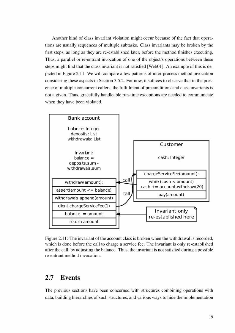
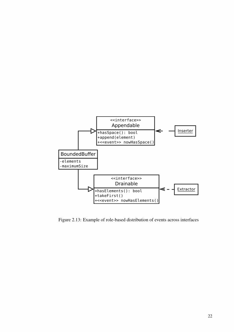
Additionally, just like handler methods are a part of the listener objects’ external inter-face, so are events a part of the publicly visible interface of announcers. In fact, exportedevents and methods can be considered equal contributions to an interface [XZ02]. We ar-gue that the ISP should apply to the interfaces where events are declared just as it appliesto those with methods. It should however be noted that events seldom constitute a fullyindependent role. For example, an event might be announced when a buffer object hasspace for inserting more elements. It would be a sensible middle ground to have both thisevent and the insert operations in a role-based interface used by clients that insert items.This arrangement is illustrated in Figure 2.13, complete with another interface to be usedby clients that extract items.
21
BoundedBuffer-elements-maximumSize
<<interface>>
Appendable+hasSpace(): bool+append(element)+<<event>> nowHasSpace()
<<interface>>
Drainable+hasElements(): bool+takeFirst()+<<event>> nowHasElements()
Inserter
Extractor
Figure 2.13: Example of role-based distribution of events across interfaces
22
3 INTER-PROCESS COMMUNICATION
Functional abstractions and encapsulated objects enable applications to delegate solvingcertain subtasks to self-contained procedures and modules. These building blocks can beput to shared libraries to increase their reusability. However, they still need to be loaded tothe application’s virtual memory space and executed locally. In distributed systems, it isalso possible to invoke functionality from other processes running on the same computer(node) and possibly even on other nodes [DSC92]. Here, we use the term process to referto an operating system construct that comprises a single protected address space and a setof associated resources. One or many threads of control can run in a single process, eachwith their own instruction pointer.
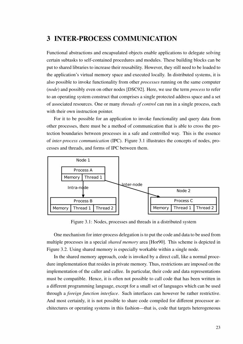
For it to be possible for an application to invoke functionality and query data fromother processes, there must be a method of communication that is able to cross the pro-tection boundaries between processes in a safe and controlled way. This is the essenceof inter-process communication (IPC). Figure 3.1 illustrates the concepts of nodes, pro-cesses and threads, and forms of IPC between them.
Node 1
Node 2
Process A
Memory Thread 1
Process B
Memory Thread 1 Thread 2
Intra-node
Process C
Memory Thread 1 Thread 2
Inter-node
Figure 3.1: Nodes, processes and threads in a distributed system
One mechanism for inter-process delegation is to put the code and data to be used frommultiple processes in a special shared memory area [Hor90]. This scheme is depicted inFigure 3.2. Using shared memory is especially workable within a single node.
In the shared memory approach, code is invoked by a direct call, like a normal proce-dure implementation that resides in private memory. Thus, restrictions are imposed on theimplementation of the caller and callee. In particular, their code and data representationsmust be compatible. Hence, it is often not possible to call code that has been written ina different programming language, except for a small set of languages which can be usedthrough a foreign function interface. Such interfaces can however be rather restrictive.And most certainly, it is not possible to share code compiled for different processor ar-chitectures or operating systems in this fashion—that is, code that targets heterogeneous
23
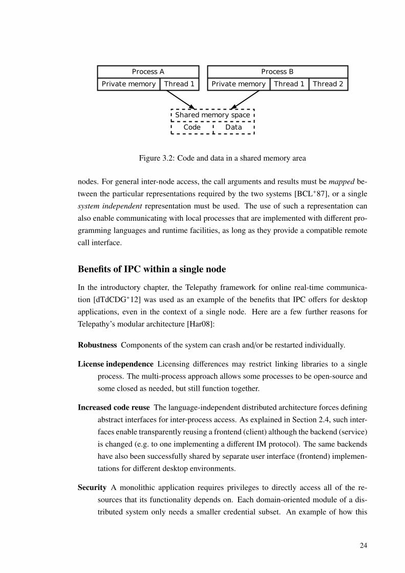
Process A
Private memory Thread 1
Shared memory space
Code Data
Process B
Private memory Thread 1 Thread 2
Figure 3.2: Code and data in a shared memory area
nodes. For general inter-node access, the call arguments and results must be mapped be-tween the particular representations required by the two systems [BCL+87], or a singlesystem independent representation must be used. The use of such a representation canalso enable communicating with local processes that are implemented with different pro-gramming languages and runtime facilities, as long as they provide a compatible remotecall interface.
Benefits of IPC within a single node
In the introductory chapter, the Telepathy framework for online real-time communica-tion [dTdCDG+12] was used as an example of the benefits that IPC offers for desktopapplications, even in the context of a single node. Here are a few further reasons forTelepathy’s modular architecture [Har08]:
Robustness Components of the system can crash and/or be restarted individually.
License independence Licensing differences may restrict linking libraries to a singleprocess. The multi-process approach allows some processes to be open-source andsome closed as needed, but still function together.
Increased code reuse The language-independent distributed architecture forces definingabstract interfaces for inter-process access. As explained in Section 2.4, such inter-faces enable transparently reusing a frontend (client) although the backend (service)is changed (e.g. to one implementing a different IM protocol). The same backendshave also been successfully shared by separate user interface (frontend) implemen-tations for different desktop environments.
Security A monolithic application requires privileges to directly access all of the re-sources that its functionality depends on. Each domain-oriented module of a dis-tributed system only needs a smaller credential subset. An example of how this
24

would apply to a system that handles various kinds of textual communication canbe found in Figure 3.3. Furthermore, the interaction between the modules can becontrolled and monitored by the messaging system that connects them together.
IPC system
Jabber backend
Internet connectivityIRC backend
SMS backend
Cellular modem
Account manager
Filesystem Conversation logger
Text chat UI
Windowing system
Figure 3.3: Distribution of privilege requirements over a modular application
Wittenburg identifies [Wit05] similar reasons for the components of a desktop com-municating together. These reasons include sharing globally unique services betweenapplications (like IM network connections in Telepathy’s case), announcing events suchas application start-up progress, and transparency on whether an invoked service is localor remote to the node. The observation that desktop services are scriptable, which meansthat they can be machine-driven, is shared with [Pet07]. In our experience, this capabilityhas also been utilized in real-world Telepathy implementations.
In summary, there are many functional benefits to be gained from making desktopapplications distributed, even within a single node. Real-world studies [BALL90] put theportion of inter-node access at just a few percent of all IPC. This might be because inter-node access is always much slower than calling a process in the same node. Hence, real-world software architectures tend to avoid overdependence on inter-node calls, whereverperformance and/or interactivity is essential. Accordingly, for most of our research, wewill focus on the inter-process communication technologies and patterns that are mostsuitable to the single-node context.
Concentrating on node-local inter-process communication allows us to side-step a fewchallenges associated with more general IPC, e.g. across the Internet. In particular, wedo not consider the complex global resource naming and location services that are usedfor announcing exported services [RSW98]. Furthermore, access control is simple to im-plement in the local context with mechanisms such as UNIX credential passing ancillary
25

messages [Lin10]. Network address translation (NAT) schemes and firewalls also signif-icantly hinder inter-node access and peer-to-peer communication through the Internet ingeneral.
The D-Bus messaging system is a main focus for the rest of this report. As shownlater, it is especially suitable for IPC within a single node. There is less attention inits design for inter-node usage. However, the Telepathy Tubes [HOD+11] mechanismextends the reach of D-Bus over the Internet. This is accomplished by piggybacking onfirewall/NAT traversal and service discovery mechanisms which already exist in instantmessaging services for purposes such as file transfer, media streaming (Voice/video overIP) and presence announcement. Thus, the usability domain of D-Bus is extended, and sois the application area of the research presented here.
The first few of the next sections present general concepts of distributed systems,through literary review. This establishes context for the study of the D-Bus messagingsystem that follows. Finally, we will set out some guidelines for how messaging protocolsshould be designed when using D-Bus and similar systems.
3.1 Remote Procedure Calls
A low-level notion of interprocess communication can be based directly on transport layernetwork services, like byte stream or datagram sockets, or pipes [Wit05]. These transferuntyped data as essentially just sequences of bytes. When a client and a service areconnected together using such means, they must obviously agree on the semantic meaningof the bytes. This agreed meaning constitutes the network protocol that is used in thecommunication. However, designing a byte-level protocol separately for each client–service application pair is cumbersome, and also steals implementation attention awayfrom the actual unique functionality of the system.
In Section 2.1, we introduced the concept of procedural programming. In that paradigm,functional abstractions provided by procedures are used as central building blocks of al-gorithms. Remote procedure calls (RPC) invoke procedure implementations from otherprocesses [BN84]. From the point of view of one writing an algorithm, classic RPCappears almost exactly like calls to procedures in the local process. In either case theimplementation of the procedure is not important, only the task it accomplishes. Thus,the implementation can as well run in some other process if that is needed e.g. to gainaccess to a certain resource owned by it. The motivation behind this IPC paradigm is thatprogrammers are used to procedural programming. Hence, emulating it in the distributedcontext requires minimal reorientation and relearning for creating distributed systems.
A key feature of RPC facilities is that they are not application-specific; the funda-
26
mental mechanism offered by them—a way to transparently transfer control to a remoteprocess—can be used in building any kind of software where procedural programming isuseful. By using RPC, low-level network protocol details do not need to be consideredin client and server design, but merely the set of procedures the server exports for clientsto call. Thus, RPC can be considered a reusable application level protocol for buildingdistributed systems that follow the procedural programming paradigm.
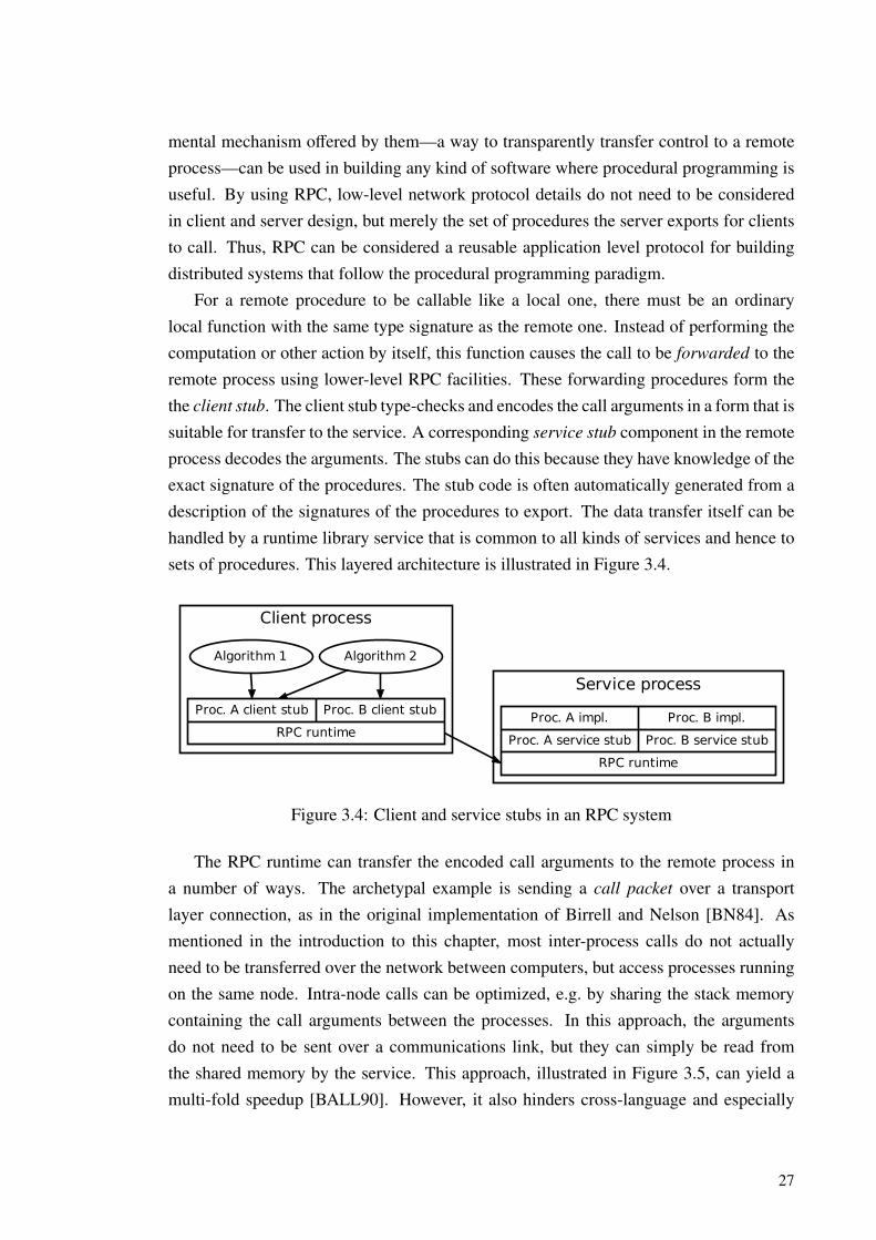
For a remote procedure to be callable like a local one, there must be an ordinarylocal function with the same type signature as the remote one. Instead of performing thecomputation or other action by itself, this function causes the call to be forwarded to theremote process using lower-level RPC facilities. These forwarding procedures form thethe client stub. The client stub type-checks and encodes the call arguments in a form that issuitable for transfer to the service. A corresponding service stub component in the remoteprocess decodes the arguments. The stubs can do this because they have knowledge of theexact signature of the procedures. The stub code is often automatically generated from adescription of the signatures of the procedures to export. The data transfer itself can behandled by a runtime library service that is common to all kinds of services and hence tosets of procedures. This layered architecture is illustrated in Figure 3.4.
Client process
Service process
Algorithm 1
Proc. A client stub Proc. B client stub
RPC runtime
Algorithm 2
Proc. A impl. Proc. B impl.
Proc. A service stub Proc. B service stub
RPC runtime
Figure 3.4: Client and service stubs in an RPC system
The RPC runtime can transfer the encoded call arguments to the remote process ina number of ways. The archetypal example is sending a call packet over a transportlayer connection, as in the original implementation of Birrell and Nelson [BN84]. Asmentioned in the introduction to this chapter, most inter-process calls do not actuallyneed to be transferred over the network between computers, but access processes runningon the same node. Intra-node calls can be optimized, e.g. by sharing the stack memorycontaining the call arguments between the processes. In this approach, the argumentsdo not need to be sent over a communications link, but they can simply be read fromthe shared memory by the service. This approach, illustrated in Figure 3.5, can yield amulti-fold speedup [BALL90]. However, it also hinders cross-language and especially
27

cross-architecture communication, because the service must be able to interpret the datain the exact form the caller code passed it to the client stub.
Client process
Service processDistributed algorithms
Client stubs
RPC runtimeShared stack
Procedure implementations
Service stubs
RPC runtimeCall trigger
Figure 3.5: Sharing the argument stack between processes
Transparent mapping services between data representations and call semantics havebeen proposed to correct the cross-system communication issues in naive RPC mecha-nisms. The aim of this is to enable integrating existing heterogeneous systems togetherwith minimal modifications. [BCL+87] The mapping adds overhead, and already implic-itly constrains the type of information that can be passed to that representable in both theclient and server systems. Based on these facts, we argue that it is better to just defineRPC messaging semantics and a data syntax in a system independent fashion. As we willsee later, this is also the approach taken by the D-Bus IPC system. The reimplementationeffort is not a major concern, as in our opinion, IPC still has not been exploited nearly asmuch as possible in the area of desktop applications.
3.1.1 Asynchrony and return values
So far we have discussed just one side of RPC, namely that of initiating calls. The returnvalues of procedures and the time at which their execution finishes are also significantin procedural programming. However, RPC mechanisms differ in their method returnsemantics. In classic RPC, the caller process is blocked until the service has informed itof the outcome of the call via the delivery of a reply packet. The reply packet is translatedto the local stub procedure’s return value, or an exception if the call failed. Only after this,client execution continues. Thus, the execution of the client and the service is effectivelysynchronized, so that only one of them is executing at a time.
In addition to errors encountered while executing a procedure, an exception can alsoresult in RPC if the communication link between the client and the service process issevered [BN84]. This can happen not only before the service starts processing the call,but also during the execution of the operation. It is also possible that even though theprocedure itself has been executed successfully, it will be impossible to tell that to the
28

caller. Thus, the state of the service is ambiguous to the client after a communicationerror. A few related scenarios are illustrated in Figure 3.6. We will revisit this subject inChapter 5 in the form of invalidation, when presenting our extended proxy construct.
Client process Service process
A successful call:
Call packet
Executing procedure
Reply packet
The client knows that the call was processed and can extract the results.
When the call packet is lost:
Call packet
Processing of the call didn’t even start.
When the reply packet is lost:
Call packet
Executing procedure
Reply packet
The call was processed, but the client can’t know that.
Figure 3.6: Ambiguity of service state after a communication failure
The synchronous semantics that are inherent to traditional remote procedure calls donot allow client execution to continue in parallel with the service. Thus, even for rawcomputations which do not have to wait for any other resource to be available besidescentral processing unit (CPU) execution time, parallelism which could net a speedup ina multiprocessing system has been lost. Similarly, to execute some operations, externalresources like network services, peripheral hardware devices or even the human user mayneed to be queried. Communicating with these resources can impose delays on the com-pletion of an operation, even if there is idle CPU time in the system. If a process blocks toinvoke such an operation, the use of CPU time may become inefficient even on a unipro-cessor system. This is because the calling process might be able to utilize the idle CPUtime for tasks such as animating its user interface [Pen08].
To regain parallel execution capability with synchronous RPC, multiple threads canbe used in the caller process, as portrayed in Figure 3.7. However, the use of threadsis programmatically unwieldy [ATK92]. The threaded approach is also not scalable to alarge amount of outstanding calls, as threads with separately allocated execution stacksneed to be spawned for the sole purpose of sitting waiting for a call to finish [WFN90].
29
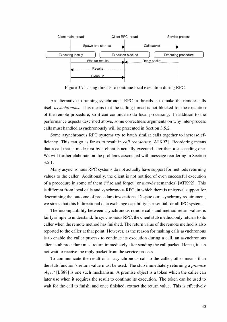
Client main thread Client RPC thread Service process
Spawn and start call Call packet
Executing locally Execution blocked Executing procedure
Wait for results Reply packet
Results
Clean up
Figure 3.7: Using threads to continue local execution during RPC
An alternative to running synchronous RPC in threads is to make the remote callsitself asynchronous. This means that the calling thread is not blocked for the executionof the remote procedure, so it can continue to do local processing. In addition to theperformance aspects described above, some correctness arguments on why inter-processcalls must handled asynchronously will be presented in Section 3.5.2.
Some asynchronous RPC systems try to batch similar calls together to increase ef-ficiency. This can go as far as to result in call reordering [ATK92]. Reordering meansthat a call that is made first by a client is actually executed later than a succeeding one.We will further elaborate on the problems associated with message reordering in Section3.5.1.
Many asynchronous RPC systems do not actually have support for methods returningvalues to the caller. Additionally, the client is not notified of even successful executionof a procedure in some of them (“fire and forget” or may-be semantics) [ATK92]. Thisis different from local calls and synchronous RPC, in which there is universal support fordetermining the outcome of procedure invocations. Despite our asynchrony requirement,we stress that this bidirectional data exchange capability is essential for all IPC systems.
The incompatibility between asynchronous remote calls and method return values isfairly simple to understand. In synchronous RPC, the client stub method only returns to itscaller when the remote method has finished. The return value of the remote method is alsoreported to the caller at that point. However, as the reason for making calls asynchronousis to enable the caller process to continue its execution during a call, an asynchronousclient stub procedure must return immediately after sending the call packet. Hence, it cannot wait to receive the reply packet from the service process.
To communicate the result of an asynchronous call to the caller, other means thanthe stub function’s return value must be used. The stub immediately returning a promise
object [LS88] is one such mechanism. A promise object is a token which the caller canlater use when it requires the result to continue its execution. The token can be used towait for the call to finish, and once finished, extract the return value. This is effectively
30

the synchronous RPC stub method split in two parts: the first merely starts the call, andthe second waits for it to complete and gives the result. Figure 3.8 illustrates RPC withpromise objects. Note how the client can only wait for one promise to be fulfilled ata time. The future mechanism [WFN90] is similar to promises, but additionally allowswaiting for multiple pending results collectively, so that they can be processed as soon asthey are available. In Section 5.1, we will present a refined object-oriented pattern thatutilizes implicit invocation to deliver asynchronous results.
Client code RPC stub Service process 1 Service process 2
call Service 1 Call packet
Promise A
call Service 2 Call packet
Promise B
Local processingReply packet
wait(Promise A)
Reply packetResults from Service 1
wait(Promise B)
Results from Service 2
Figure 3.8: RPC with promise objects
3.2 Proxies
In Section 2.1, we described how data abstraction makes it possible to change the inter-nal representation of objects without affecting clients that access them. For a monolithicapplication, the benefit of this might be restricted to not needing to re-compile the clientmodules when a change is made. In other words, merely time taken for compilation aftera change is conserved. However, if the application is distributed, it is hard to arrange fora re-compile or re-link to occur as needed, e.g. when a service binary has been upgraded,so this alone is a significant benefit [Sha86]. Of course, if there are incompatible changesto an object interface, e.g. some methods are completely removed, or their signature hasbeen changed, even a re-compile does not suffice for either monolithic or distributed ap-plications. The client source code must instead be manually “ported” to the new interfacein both of these cases.
The proxy pattern of Shapiro [Sha86] promotes object-oriented data abstraction andencapsulation for inter-process communication. A proxy object lives in a client’s address
31
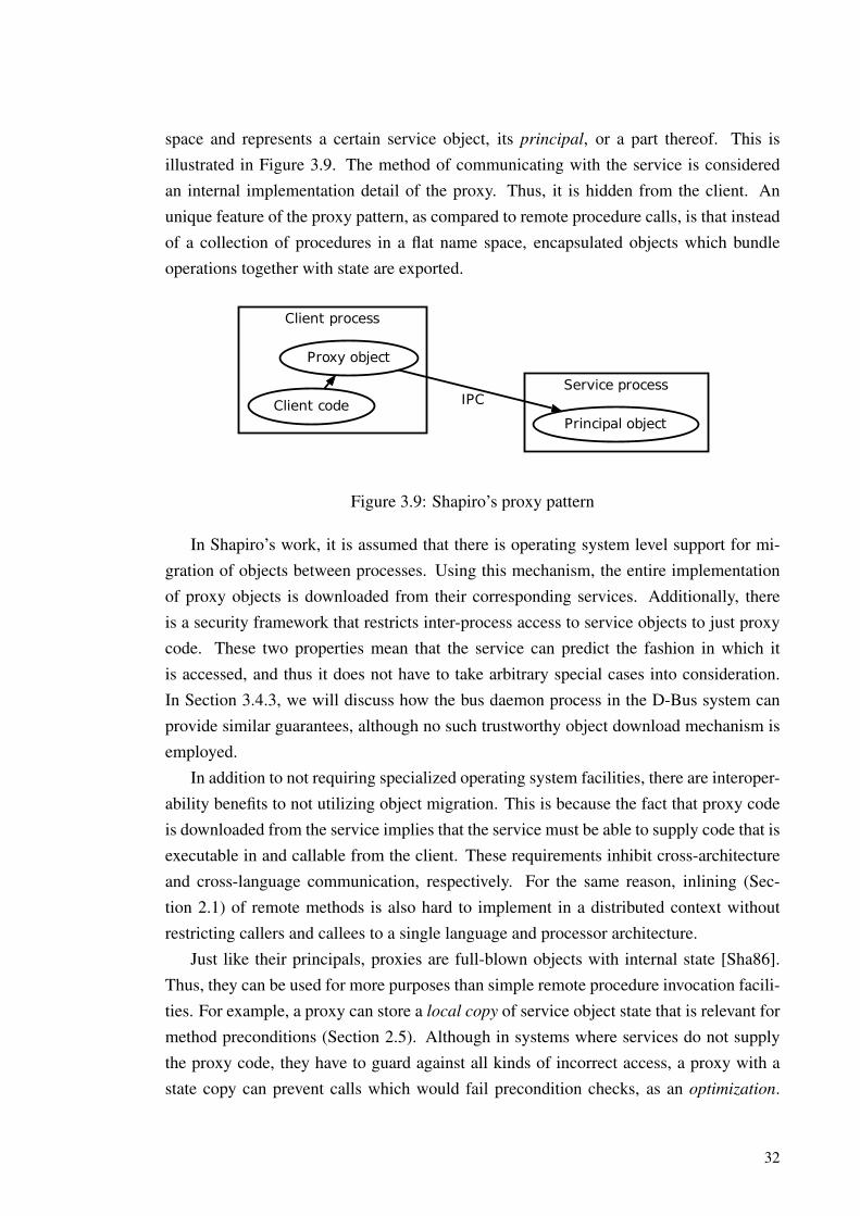
space and represents a certain service object, its principal, or a part thereof. This isillustrated in Figure 3.9. The method of communicating with the service is consideredan internal implementation detail of the proxy. Thus, it is hidden from the client. Anunique feature of the proxy pattern, as compared to remote procedure calls, is that insteadof a collection of procedures in a flat name space, encapsulated objects which bundleoperations together with state are exported.
Client process
Service process
Client code
Proxy object
Principal object
IPC
Figure 3.9: Shapiro’s proxy pattern
In Shapiro’s work, it is assumed that there is operating system level support for mi-gration of objects between processes. Using this mechanism, the entire implementationof proxy objects is downloaded from their corresponding services. Additionally, thereis a security framework that restricts inter-process access to service objects to just proxycode. These two properties mean that the service can predict the fashion in which itis accessed, and thus it does not have to take arbitrary special cases into consideration.In Section 3.4.3, we will discuss how the bus daemon process in the D-Bus system canprovide similar guarantees, although no such trustworthy object download mechanism isemployed.
In addition to not requiring specialized operating system facilities, there are interoper-ability benefits to not utilizing object migration. This is because the fact that proxy codeis downloaded from the service implies that the service must be able to supply code that isexecutable in and callable from the client. These requirements inhibit cross-architectureand cross-language communication, respectively. For the same reason, inlining (Sec-tion 2.1) of remote methods is also hard to implement in a distributed context withoutrestricting callers and callees to a single language and processor architecture.
Just like their principals, proxies are full-blown objects with internal state [Sha86].Thus, they can be used for more purposes than simple remote procedure invocation facili-ties. For example, a proxy can store a local copy of service object state that is relevant formethod preconditions (Section 2.5). Although in systems where services do not supplythe proxy code, they have to guard against all kinds of incorrect access, a proxy with astate copy can prevent calls which would fail precondition checks, as an optimization.
32

Additionally, the state copy can be used to run some operations locally without accessingthe service [Sha86]. The runnable operations are those with no mutating side effects onthe service object, i.e. observation operations (“getters”). Figure 3.10 depicts possibleoperation of a proxy with a local state copy. We will formalize a state mirroring proxydesign that uses D-Bus facilities, and will show its usefulness in environments that arerestricted to asynchronous invocation, in Chapter 5.
Client code Proxy object Service object
‘‘Bank account’’
State: balance=1000
getBalance()
1000
withdraw(500)
Call: withdraw(500)
OK
OK
getBalance()
500
withdraw(1000)
Error: Insufficient balance!
Figure 3.10: Operation of a proxy object with a local state copy
Primitive values and simple records composed of them can usually be transferred asbyte-for-byte copies when they are used as RPC arguments and return values. A raw copyof an object’s internal data can not however be usefully interpreted without the abstractsemantics that the object’s public inspection operations give to it. Thus, in systems thatdo not support migration of the implementations of object operations, objects can not beeasily passed between processes as arguments or return values. Furthermore, the purposeof some objects is to govern access to a single shared resource. Duplicating such anobject would be counterproductive, because then multiple instances would try to accessthat resource. These challenges seem to be the motivation behind classifying objects aseither service objects that offer abstract functionality or data objects, which are just simplerecords [OPSS93]. Passing the name/address of an object and constructing a proxy for
33

it in an IPC receiver’s address space can be used to provide transparent shared access tonon-migratable objects [EGD01]. The use of a proxy to represent an object returned by aservice method is illustrated in Figure 3.11.
<<service object>>
Car-engine: Engine
+getEngine(): pointer to Engine
<<service object>>
Engine-numCylinders-bore-stroke
+getDisplacement()
<<proxy>>
Car+getEngine()
<<proxy>>
Engine+getDisplacement()
returns
calls
calls
Service process
Client process
Figure 3.11: Representing an returned service object with a proxy
3.2.1 Proxy-principal communication protocol
In implementations of the proxy pattern that are based on object migration, proxy codecan directly access private interfaces of service objects, as the services can trust themto do so responsibly. Hence, a predefined protocol with a restricted set of invokableoperations is not needed [Sha86]. However, in other kinds of systems, there must bean adaptor-style object in the service, which is analogous with the RPC service stub.The adaptor implements the service export protocol and binds it to calls to the serviceobject implementation. The relationship between adaptors, proxies and principal objectsis shown in Figure 3.12. The role of the adaptor is fulfilled by message converters inthe distributed knowledge object system of Huang and Duan [HD93]. Both the proxiesand the message converters in this system are written by hand, along with the principalobjects.
The proxy methods that call the service and the message subtypes in the communi-cation protocol between the proxy and the adaptor both map to the operations that theadaptor invokes on the principal object. Designing these entities separately is therefore
34

Client process
Service process
Client code
Proxy object
Adaptor object
Principal object
Figure 3.12: Adaptor objects in a proxy-based IPC system
redundant work. The Proxify++ code generator tool in the Choices system inspects C++
class header files to gather information on operations that are marked for export to clients.Then, it generates the corresponding proxies [DSC92]. Thus, the interface is designedonly once when writing the service-side implementation. However, in that system, spe-cial annotations that detail the semantics of the method interface are needed to guide theencoding of parameters for transfer (marshalling).
In the spirit of explicit interface oriented design (Section 2.4), we argue that oneshould not try to extract IPC interfaces from existing object implementations, especiallyif they need to be augmented with further metadata. Instead, all of this knowledge shouldbe encoded in a separate interface specification, which will dictate the operations thatmust be supported by concrete implementations. This is the approach taken in the JavaRMI and CORBA systems, for example. In Chapter 6, we will propose an XML-basedinterface description language (IDL), that can be used to generate proxies for use with theD-Bus messaging system.
Most of our research is concerned with the client side of IPC systems. Hence, weoften blur the line between service adaptors and principal objects in our examples, andrefer to them together as service objects.
3.3 The Publish/Subscribe Paradigm
Remote procedure calls hide the complexity of network communication from inter-processprocedural programming, and the proxy pattern translates the benefits of object-orienteddata abstraction (encapsulation) to the distributed setting. However, in both paradigmsthe entity that initiates communication must still specify the receiver using some refer-ence. This can be an explicit address or an abstract name to be translated by a nameservice. Additionally, the exact operation invoked is always directly specified in RPC,although proxies can transparently remap [DSC92] or even avoid calls depending on thecapabilities and state of the remote object, which they can locally mirror [Sha86]. Hence,
35

these mechanisms lack the kind of full decoupling between information producers andconsumers (event announcers and receivers) that is achieved by implicit invocation (Sec-tion 2.7).
Event-driven communication can be facilitated in a distributed setting by allowingpublishers to announce events on some kind of a shared medium, where messages arerouted to subscribers based on their registered interests [EFGK03]. The interests areregistered on the connecting service, and not using application-specific facilities imple-mented by the publishers. Hence, the publishers are fully decoupled from the identitiesof the consumers for the events they announce. Additionally, if the rules specifying aninterest are based solely on the event itself and not on the identity of the entity whichproduced it, producers also remain anonymous to their consumers [OPSS93]. The multi-plicity of producers and consumers is also flexible: Events from one or more publisherscan be routed to an arbitrary number, including zero, of subscribers with a matching in-terest. The basic structure of the publish/subscribe paradigm [EFGK03] is illustrated inFigure 3.13.
Publishers Messaging system Subscribers
1
2Message routing
publish(event A)
3
publish(event B)
Event interests
uses2deliver(event A)
3
deliver(event A)
1register
Figure 3.13: The publish/subscribe paradigm
How the interesting events are specified varies in concrete publish/subscribe messag-ing implementations. In subject/topic-based systems, events are labeled with a subjectidentifier and delivered to all receivers subscribed to that subject. Thus, all events undera certain topic can be thought to be delivered to a group of of subscribers. This one-to-many mapping is only altered when subscriptions are made or broken, so it does not needto incur a per-message cost [OPSS93].
In contrast to the above, content-based systems allow subscriptions to be based onmultiple meta-data attributes of the events, and sometimes even on (parts of) the pay-load itself. As expressing these kinds of interests is more complex than naming a sub-ject, a subscription language needs to be used to specify them. Rules written in thislanguage are interpreted by the messaging system to do message routing. The rules spec-ify ranges of values for certain properties of messages that should make them delivered
36

to the subscriber. Matching messages against the content-based rules implies additionalper-message routing work. However, it allows more fine-grained rules than topic-basedsubscription. Thus, it can help avoid unnecessary message transfer and execution contextswitches which could result from too broad rules that cause uninteresting events to bedelivered to receivers [EFGK03]. Furthermore, when the majority of the event filteringwork being done in a central component, common rule subexpressions can be evaluatedtogether as an optimization [EGD01]. The match rules of D-Bus [PCL+12] are also aform of content-based subscriptions. Our D-Bus-based extended proxy construct lever-ages fine-grained match rules to avoid redundant communication, as will be explained inSection 5.3.
A further refinement to the paradigm is representing events as full-fledged objects—that is, as abstract entities defined by their operations, and belonging to one or more classhierarchies. Implementing this requires an object migration mechanism, and as explainedearlier, the use of such mechanisms imposes restrictions on language interoperability. Themain motivation for the use of first-class event objects is gaining type safety in the eventcommunication [EGD01]. It is however possible to do type-checking without the eventsbeing objects just as it is done for method arguments, if the type signatures of events arespecified in an explicit interface description alongside the methods. This is the case in theinterface description language we present in Chapter 6.
Although implicit invocation has many uses, certain drawbacks make regular asyn-chronous RPC calls better suited for some tasks. Hence, it is useful to utilize both ofthese communication paradigms in a distributed system. Events are by nature fire-and-forget; it is not possible to know whether they were delivered to certain producers or not.Hence, for cases where it must be known that an action was properly undertaken, RPC ismore suitable [EFGK03]. A classical example is the trading floor [EGD01]: Stock priceupdates are inherently multicast-type events, where the most recent update of a given se-curity’s price completely supersedes earlier ones. However, the outcome of a single act ofpurchasing or selling a stock, and that it is attempted exactly once, is very crucial. Thoseactions should therefore be explicitly invoked operations. A single messaging system canbe used to transport operation invocations and replies in addition to events [OPSS93].This is also reflected in the message types supported by D-Bus (Section 3.4.2).
Concrete publisher and subscriber instances communicating together can be added,removed, altered and replaced freely at runtime due to identity decoupling. A relateddecoupling dimension is that of temporal decoupling: the medium can store the eventmessages in non-volatile memory, and forward them only when a consumer is preparedto retrieve them. If this is done, no events are lost even in cases such as temporary networkdowntime or consumer crashes [EFGK03].
37
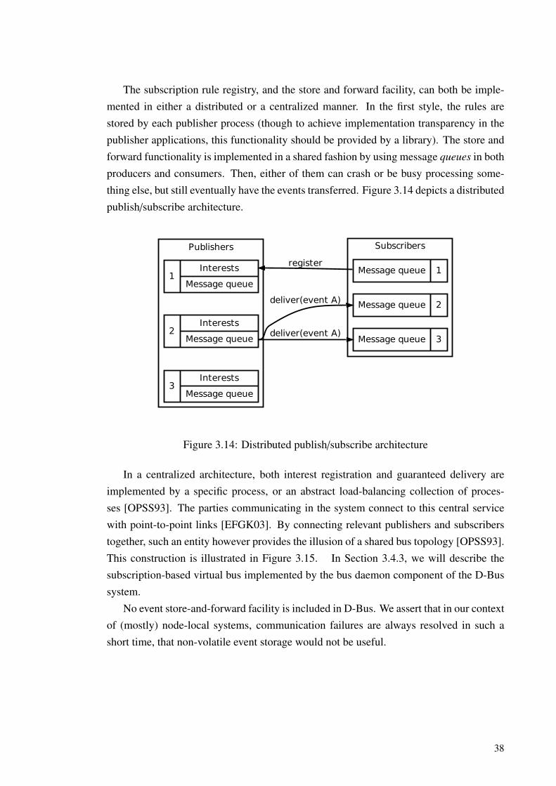
The subscription rule registry, and the store and forward facility, can both be imple-mented in either a distributed or a centralized manner. In the first style, the rules arestored by each publisher process (though to achieve implementation transparency in thepublisher applications, this functionality should be provided by a library). The store andforward functionality is implemented in a shared fashion by using message queues in bothproducers and consumers. Then, either of them can crash or be busy processing some-thing else, but still eventually have the events transferred. Figure 3.14 depicts a distributedpublish/subscribe architecture.
Publishers Subscribers
1Interests
Message queue
2Interests
Message queue
Message queue 2deliver(event A)
Message queue 3deliver(event A)
3Interests
Message queue
Message queue 1register
Figure 3.14: Distributed publish/subscribe architecture
In a centralized architecture, both interest registration and guaranteed delivery areimplemented by a specific process, or an abstract load-balancing collection of proces-ses [OPSS93]. The parties communicating in the system connect to this central servicewith point-to-point links [EFGK03]. By connecting relevant publishers and subscriberstogether, such an entity however provides the illusion of a shared bus topology [OPSS93].This construction is illustrated in Figure 3.15. In Section 3.4.3, we will describe thesubscription-based virtual bus implemented by the bus daemon component of the D-Bussystem.
No event store-and-forward facility is included in D-Bus. We assert that in our contextof (mostly) node-local systems, communication failures are always resolved in such ashort time, that non-volatile event storage would not be useful.
38
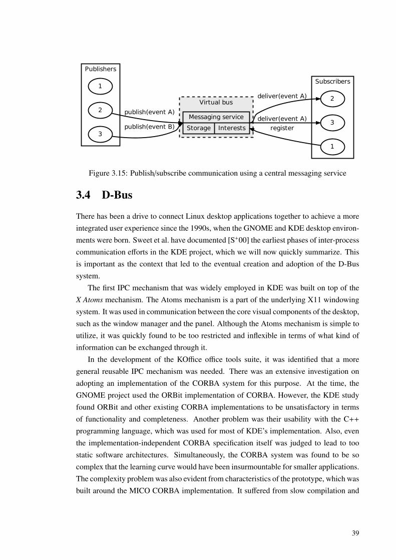
Publishers
Virtual bus
Subscribers1
2Messaging service
Storage Interests
publish(event A)
3publish(event B)
2deliver(event A)
3deliver(event A)
1
register
Figure 3.15: Publish/subscribe communication using a central messaging service
3.4 D-Bus
There has been a drive to connect Linux desktop applications together to achieve a moreintegrated user experience since the 1990s, when the GNOME and KDE desktop environ-ments were born. Sweet et al. have documented [S+00] the earliest phases of inter-processcommunication efforts in the KDE project, which we will now quickly summarize. Thisis important as the context that led to the eventual creation and adoption of the D-Bussystem.
The first IPC mechanism that was widely employed in KDE was built on top of theX Atoms mechanism. The Atoms mechanism is a part of the underlying X11 windowingsystem. It was used in communication between the core visual components of the desktop,such as the window manager and the panel. Although the Atoms mechanism is simple toutilize, it was quickly found to be too restricted and inflexible in terms of what kind ofinformation can be exchanged through it.
In the development of the KOffice office tools suite, it was identified that a moregeneral reusable IPC mechanism was needed. There was an extensive investigation onadopting an implementation of the CORBA system for this purpose. At the time, theGNOME project used the ORBit implementation of CORBA. However, the KDE studyfound ORBit and other existing CORBA implementations to be unsatisfactory in termsof functionality and completeness. Another problem was their usability with the C++
programming language, which was used for most of KDE’s implementation. Also, eventhe implementation-independent CORBA specification itself was judged to lead to toostatic software architectures. Simultaneously, the CORBA system was found to be socomplex that the learning curve would have been insurmountable for smaller applications.The complexity problem was also evident from characteristics of the prototype, which wasbuilt around the MICO CORBA implementation. It suffered from slow compilation and
39

execution, excessive memory usage and unsatisfactory stability.The DCOP system was then created as a ”simpler CORBA”, to bring the benefits of
generic IPC to KDE without the complexity imposed by CORBA. DCOP is based onthe X Window System Inter-Client Exchange (ICE) mechanism, which has been a partof all contemporary X Window System releases in the X11R6 series. However, ICEis a very low-level mechanism. For example, its type system is restricted to primitiveinteger, boolean and character types and homogenous lists of those [SB94]. For thisreason, DCOP uses the QDataStream facility from the Qt framework for serializationand de-serialization of more complex data [S+00]. While Qt is the basis of KDE, it is notused in the GNOME project, and hence this design choice hampers interoperability withGNOME and other non-Qt systems [Wit05].
D-Bus is a full-featured IPC system. Its type system is designed to be flexible andextensible enough so that it can be used in both GNOME and KDE, without additional in-compatible typing and (de-)serialization layers above it [Lov05]. It has since been adoptedas the sole high-level IPC mechanism by both of these desktop environments, in which ithas replaced CORBA and DCOP, respectively. As such, D-Bus has widespread availabil-ity, which has enabled cross-platform projects to depend on it [AFF+09].
In the following sections, we will analyze the features and qualities of the D-Bus sys-tem in the context of existing research on object-orientation and inter-process communi-cation. The analysis is based on the canonical specification document, which is publishedas a freedesktop.org standard [PCL+12]. We will specifically focus on the propertieswhich are the most important for the principles and patterns we introduce later. Specifi-cally, we deliberately ignore issues such as the features for peer authentication, messagevalidation, and the lowest level details on the binary representation of messages.
3.4.1 Object model
Services export their functionality over D-Bus in the form of objects, which typically,though not necessarily, are backed by concrete native objects in the address space of theservice process. The D-Bus object model does not have a concept of classes (as definedin Chapter 2). Instead, the access interface of objects is determined exclusively by theexplicit interfaces (Section 2.4) that a particular instance implements.
The objects in a single process are identified uniquely by object paths of the form/rooms/Third_floor/301, that is, a series of elements, which are preceded and sepa-rated by slash (/) characters. The elements consist of alphanumeric characters and under-scores. Object paths are usually mapped to memory addresses of real objects by runtimefacilities, but unlike raw memory pointers, they provide an abstract, architecture indepen-dent, human-readable and hierarchical identifying system. It is common to leverage these
40
benefits e.g. by exporting some kinds of objects at a fixed well-known path. For example,the Telepathy runtime debugging facility is always present at /org/freedesktop/Te-lepathy/debug. It is also common to give semantics to elements at certain levels of thehierarchy, such as in the paths of Telepathy Account objects. These paths include the net-work protocol and backend implementation used for it as the second- and third-from-lastelements, respectively [dTdCDG+12].
The interfaces that D-Bus objects implement are in turn referred to by names likeorg.freedesktop.Telepathy.Connection. Although at the time of writing, thereexists no global registry of D-Bus interfaces, an Internet domain name that belongs tothe designer or user organization is often included in a reversed form before a number oflocally identifying elements, to attain global uniquity for interface names.
Arguably the most important members of interfaces are methods, which are functionalabstractions, as defined in Section 2.1. Methods are named in a CamelCase fashion, andcan take an arbitrary number of parameters and also return an arbitrary number of returnvalues. The interface defines the types of these items of data for each method, so that typecompatibility can be enforced. The details of the D-Bus type system will be elaboratedmore in the next section.
Instead of finishing successfully and producing the expected set of return values, aD-Bus method invocation can also result in an error. D-Bus errors are analogous toexceptions, which can happen for process-local calls (Section 2.6). Errors have a type,which is a global name with a form similar to that of interface names. For example,the error org.freedesktop.Telepathy.Error.Channel.InviteOnly is used in theTelepathy framework to indicate the failure to join a chat room for which an invite isrequired. Errors can have any kind of data associated with them. However, usually thereis just a single string argument that carries a human-readable debugging message, whichdescribes the error in more detail.
Implicit invocation (Section 2.7) is included in D-Bus in the form of signals, which areemitted on a particular object instance, but are not targeted towards any specific receiverobject. Signals may include arguments. The presence and type of these arguments isdefined in the description of the interface which a signal is defined in, as is the case formethod parameters. Unlike methods, there is no response to signals, such as a resultgathered from the objects listening to it, or even acknowledgement of any process havingreceived it.
As D-Bus interfaces are concerned with how objects are accessed, instead of howthey are implemented, they do not include any members with less-than-public accessibil-ity. In a typical encapsulated native object, the data representation would be private tothe object—an implementation detail of the data abstraction the object provides. Such
41

Table 3.1: D-Bus basic types
Name Code DescriptionBYTE y Integer in (0 . . . 255)BOOLEAN b Truth value: 1 (TRUE) or 0 (FALSE)INT16 n Integer in (−32768 . . . 32767)UINT16 q Integer in (0 . . . 65535)INT32 i Integer in
(−231 . . . 231 − 1
)UINT32 u Integer in
(0 . . . 232−1
)INT64 x Integer in
(−263 . . . 263 − 1
)UINT64 t Integer in
(0 . . . 264 − 1
)DOUBLE d IEEE 754 double-precision floating point numberSTRING s Arbitrary-length string of characters in UTF-8 encodingOBJECT_PATH o Path to a D-Bus objectSIGNATURE g Type signature of other data
details are not relevant for D-Bus object interfaces; however, they can include publiclyaccessed attributes in the form of properties. These do not need to be backed directly byinstance variables of a compatible type, but are usually implemented in services througha getter (inspection) function. If a property is mutable, there is also a corresponding setter(mutator) function. The Properties and ObjectManager interfaces, and some parts ofthe design of our state caching proxies, all presented later, are specifically concerned withaccessing, transferring and updating these properties of objects.
3.4.2 Message format
Inter-process communication between D-Bus objects takes the physical form of messages,which consist of a header and a body. The header specifies how the message should beinterpreted, and the body carries the actual data. In particular, the header includes mostof the information needed for routing the message to its intended recipient(s).
Type system
All values in D-Bus messages, including both the header and the body, are representedusing a well defined type system. The smallest unit of typing is that of the basic types.Each basic type has an associated signature code, which can represent it by itself or aspart of a signature of a more complex type. Table 3.1 lists these data types of D-Bus.
The simplest way to combine primitive types together is concatenation. For example,the signature iis would mean that two 32-bit signed integers are followed by a characterstring. In this case, all three values are separate. A distinct concept is the STRUCT, which
42

is represented in signatures by parentheses, such as in s(yb). In this signature, a stringvalue is followed by a single structured value, which is composed of a byte-sized integerand a boolean.
The basic types belong to a larger group, that of single complete types. The signatureii has two single complete types following each other, while a STRUCT groups singlecomplete types together to form a new single complete type. Another way to form newcomplete types is the ARRAY construct. Arrays are represented in signatures by the ‘a’character followed by a single complete type, which determines the type of elements inthe resulting homogenous sequence. For example, the signature ai specifies a list ofintegers, and a(uu) a list of pairs of 32-bit unsigned integers.
The final primitive for forming complex types is the DICT, which is semantically akey-value mapping. Its keys must be unique, but can be of any basic type. The valueassociated with each key can be of any single complete type. A string-keyed dictionarywhich has integer triples as values would be written as a{s(iii)}.
The VARIANT type is represented in signatures by the ‘v’ character. A variant can holda value of any single complete type. To enable the receiver to interpret the value correctly,variants also carry the type signature of the value. Variants also belong to the group ofsingle complete types, so they can be used as array elements and mapping values.
An important property of all single complete types is the ability to nest them in vari-ants, structs, arrays and dictionary values. There is a limit to the maximum depth of thenesting, presumably to avoid security and reliability issues caused by stack overflows inmessage handling code. However, this limit is well beyond any practical uses, at 64 levelsin total. This means that constructs such as arrays of arrays of structures are supported.For example, the signature aa(sii) would be interpreted as a two-dimensional array of(STRING, INT32, INT32) triples. This nesting capability is what makes the type system ofD-Bus truly powerful. The system is able to encode virtually any kind of complex valuesin a programming environment- and architecture-independent fashion.
We will use D-Bus signatures later on to describe the types of parameters and returnvalues of D-Bus methods, of arguments of signals, and those of properties. As an example,consider the following declaration of a single method. The method takes an array offloating-point values as its only parameter, and produces as its result a single number, thesum of the values in the array.
com.example.Calculator.Sum(ad: Numbers) → d: Total
Message types
The D-Bus message header has a field for the type of the message, which determines theset of type-specific additional header fields applicable to it, and the interpretation of its
43

body. The first such type is METHOD_CALL, which requests starting the invocation of amethod. In essence, this is the call packet (Section 3.1) of D-Bus. The method to invokeis identified in these messages by an interface name and the name of the method in thatinterface. A path is also given to the object instance on which the method should beinvoked.
The body of METHOD_CALL messages consists of the parameters passed in to themethod, if it requires any. With the description of the interface that contains the method,the signature of the body can be checked against the type signature of the method. Allparameters are passed by value—reference arguments are not supported. However, as theobject path is a possible value type, mutable reference parameters can be simulated fornon-copiable object entities by proxying, as explained earlier in Section 3.2.
The header for all D-Bus messages carries a serial number field, which uniquely iden-tifies messages from a single sender (though not globally amongst all senders). This serialnumber of method call messages is used to associate with them later METHOD_RETURNmessages, which represent successful completion of method execution. The same goesfor ERROR messages, which indicate that an D-Bus error/exception occurred. These mes-sages together constitute the reply packets (Section 3.1.1) of D-Bus. As the “packet”terminology never seems to be used in the context of D-Bus, we will exclusively refer toD-Bus call and reply packets as messages.
The header of D-Bus reply messages contains a reply_serial field. This is set tothe serial number of the call message that they should be interpreted as a response to.Figure 3.16 illustrates the use of this field in practice.
Client process Service object
METHOD_CALLmember=Disconnect
serial=1
METHOD_CALLmember=Disconnect
serial=2
METHOD_RETURNreply_serial=1
ERRORreply_serial=2
"com.example.AlreadyDisconnected"
Figure 3.16: The function of the reply_serial field in D-Bus
Method return messages have two purposes. First, they indicate successful completionof a method’s execution. If the method produces return values, the message also servesas a carrier for them. This is similar for error messages, except that their contents areusually limited to the D-Bus name of the error. Return messages are only generated andsent by the process that implements the method. However, errors can be generated any-
44

where in the messaging system, e.g. because the service process has crashed or otherwisebecame unreachable or unresponsive. Having separate messages for starting method callsand conveying their result enables D-Bus methods to be invoked asynchronously. How-ever, it is still possible for callers to receive results and in general, know the outcome ofoperations which they invoked. When this is not needed, the NO_REPLY_EXPECTED flagcan be set in the header of method call messages to prevent a reply from being generated.This can be useful to avoid the cost of sending and delivering the reply message in caseswhere the result would anyway be ignored by the caller.
Signal emissions are represented by messages with the type SIGNAL. Similarly toMETHOD_CALL messages, their body contains the arguments of the event. However, intheir case, the object path does not identify a receiver for the message, but instead theobject from which the signal originated.
Signal messages are delivered to objects in listening processes primarily based onmatch rules, which are explained in the next section, amongst other subjects related tothe D-Bus bus daemon process. However, before that, we will close our treatise of theformat of D-Bus messages with a few words on their representation for transfer overcommunication channels.
Wire representation
Data in textual formats like XML can be easily transferred between systems using net-work protocols that are intended for transporting human readable text. However, typicalprocessors expect an architecture-specific binary representation for values that are usedfor arithmetic in executable code. Textual data needs to be converted to this native binaryformat for processing, which can be expensive. A common difference in the native repre-sentations of different processor architectures is whether the most or least significant bitsof a multi-byte value should be stored first in memory. This is called endianness.
D-Bus uses a binary format to encode messages for transfer. Thus, conversions be-tween a textual format for communication and a binary format for processing are notneeded. However, D-Bus specifies binary layout details such as alignment and paddingfor all kinds of values that are supported by its type system. Additionally, the messageheader contains a flag indicating the endianness of data in messages, which a receiver canuse to convert the values to its native endianness if there is a mismatch. These facts puttogether mean that although messages are transported in a binary format, this format isarchitecture independent. Hence, D-Bus can be used for arbitrary cross-machine com-munication as well. The ”receiver converts” paradigm means that endian conversions areavoided in local-node usage, which improves performance.
45
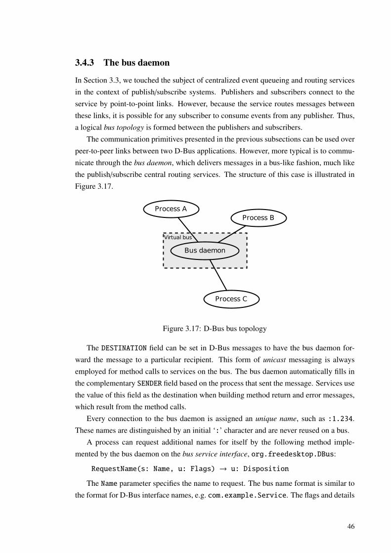
3.4.3 The bus daemon
In Section 3.3, we touched the subject of centralized event queueing and routing servicesin the context of publish/subscribe systems. Publishers and subscribers connect to theservice by point-to-point links. However, because the service routes messages betweenthese links, it is possible for any subscriber to consume events from any publisher. Thus,a logical bus topology is formed between the publishers and subscribers.
The communication primitives presented in the previous subsections can be used overpeer-to-peer links between two D-Bus applications. However, more typical is to commu-nicate through the bus daemon, which delivers messages in a bus-like fashion, much likethe publish/subscribe central routing services. The structure of this case is illustrated inFigure 3.17.
Process A
Bus daemon
Process B
Process C
Virtual bus
Figure 3.17: D-Bus bus topology
The DESTINATION field can be set in D-Bus messages to have the bus daemon for-ward the message to a particular recipient. This form of unicast messaging is alwaysemployed for method calls to services on the bus. The bus daemon automatically fills inthe complementary SENDER field based on the process that sent the message. Services usethe value of this field as the destination when building method return and error messages,which result from the method calls.
Every connection to the bus daemon is assigned an unique name, such as :1.234.These names are distinguished by an initial ‘:’ character and are never reused on a bus.
A process can request additional names for itself by the following method imple-mented by the bus daemon on the bus service interface, org.freedesktop.DBus:
RequestName(s: Name, u: Flags) → u: Disposition
The Name parameter specifies the name to request. The bus name format is similar tothe format for D-Bus interface names, e.g. com.example.Service. The flags and details
46

on the disposition return value are only relevant when multiple processes try to claim thesame bus name. For our purposes, it suffices to know that with certain flags, the operationonly succeeds if the process obtains the name, and fails otherwise.
The destination field of a message can be filled with either a unique name or any otherbus name successfully claimed by a service. The bus daemon routes unicast messagesaccording to all the mappings established with RequestName. The effect of sending amessage to a non-unique name is the same as setting the destination to the unique nameof the process which owns that name. These mappings can be broken by their owner bycalling the following method of the bus service interface:
ReleaseName(s: Name) → u: Result
When a name is successfully acquired or released by a process, the bus daemon emitsthe NameOwnerChanged signal on the same interface. Other processes can listen to thissignal to be notified of services appearing and exiting. To specify which names are inter-esting, D-Bus interface specifications often define certain well-known names or patternsfor them, for implementations of particular functionality. For example, Telepathy protocolbackends register names like
org.freedesktop.Telepathy.ConnectionManager.gabble
where the last component is the name of the executable [dTdCDG+12].Signal messages can specify a destination as well, to make them routed in a uni-
cast fashion. However, usually this is left out and they are delivered to interested re-ceivers according to match rules. The match rules are specified as strings of the formkey1=’val1’,key2=’val2’,. . . such as
interface=’org.freedesktop.MediaPlayer’,member=’StatusChange’
Table 3.2 partially describes the semantics of this subscription language. The expres-siveness of match rules makes D-Bus a content-based publish/subscribe system. How-ever, there are some restrictions on how content can be matched, as detailed in the table,so it is not a fully general one. Match rules can be added and removed at runtime, soD-Bus supports dynamically altering the connections between event announcers and lis-teners (Section 2.7). This is done by calling the following two methods of the bus serviceinterface:
AddMatch(s: Rule) → nothing
RemoveMatch(s: Rule) → nothing
47

Table 3.2: Some semantics of D-Bus match rules
Key Example value Matches ontype signal The type of the message.interface org.freedesktop.DBus The name of the interface the method or sig-
nal the message pertains to is a member of.member RequestName The name of the method or signal (member
of the interface).path /rooms/301 The path to the object to invoke a method on,
or which has emitted a signal.argN “John Doe” The value of the Nth argument of the (method
call or signal) message, starting from arg0for the first argument. Restricted to string ar-guments.
arg0namespace com.example The initial components of the first ar-gument, which has to be a string for-matted like a D-Bus interface nameor bus name. The example wouldmatch com.example.EchoService andcom.example.MusicPlayer, but notcom.examplesoftwarecompany.Editor.This is useful for watching a family of namesby listening to the NameOwnerChangedsignal, as the bus name for which the ownerchanged is the first argument in that signal.However, there are no corresponding matchrule keys for arguments other than the firstone.
path_namespace /rooms Similarly, the initial components of the pathof the object which the message pertains to.The example would match /rooms/301 and/rooms/415 etc. but not /roomservice.
48

If a method call is directed to a non-unique bus name that no process currently owns,the bus daemon will attempt to start the service that should provide it. The mapping ofbus names to executables that will register them are stored in service description files.If the name is found from those files, the daemon will start the service and wait until ithas connected to the bus and requested the name. This is called service activation. Themethod call message that caused the service to be activated will be delivered afterwards.
Access control
Any number of D-Bus bus daemon processes can run on a single machine, to create mul-tiple virtual buses. However, there is usually one machine-wide system bus for systemservices, shared between all users, and one bus for each logged in user session (ses-
sion bus). The session bus is typically configured to allow all traffic between connectedprocesses, but the system bus restricts access to destructive actions and confidential in-formation. However, the session buses only allow processes run by their owner user toconnect.
To enforce the differences between system, session and other kinds of buses, the busdaemon has a configurable security policy. The security policy can, for example, beused to only allow particular users and executables to claim a particular well-known busname, to prevent spoofing. Also, access to methods and other service properties can berestricted based on user credentials. These restrictions can be used to prevent malicioususe of services. In this way, the bus daemon can provide some security guarantees, whichwould be implicit in a system based on runtime proxy object migration, as we detailed inSection 3.2.
3.4.4 The Properties interface
In addition to the bus service interface implemented by the bus daemon, the D-Bus spec-ification defines a few other standard interfaces. These interfaces contain generic func-tionality, which is intended to be useful for many kinds of applications.
In Section 3.4.1 we mentioned that in addition to methods and signals, D-Bus inter-faces may include properties. There is a standard interface, which objects can implementto expose access to properties on their other interfaces. This interface, org.freedesk-top.Properties, is presented in Listing 3.1.
Suppose an object implements the standard Properties interface, and additionallythe Counter interface presented in Listing 3.2. The semantics of the Counter interfaceshould be self-explanatory. A call of Get("com.example.Counter", "CurrentVal-ue") could be used to discover the current value of the counter. The value will be packed
49

Get(s: Interface, s: Property) → v: Value
Set(s: Interface, s: Property, v: New_Value) → nothing
GetAll(s: Interface) → a{sv}: Properties
PropertiesChanged(s: Interface, a{sv}: Changed,as: Invalidated) [signal]
D-Bus interface 3.1: org.freedesktop.Properties
in a D-Bus VARIANT value, as per the return type of the Get method.
Increment() → nothing
Reset() → nothing
u: CurrentValue [read-write property]
t: LastReset [read-only property]
D-Bus interface 3.2: com.example.Counter
The GetAllmethod can be used to download all of the properties on a given interfacean object implements. This is functionally equivalent to making separate Get calls todiscover the value of each property, as long as their values do not change between the calls.However, with GetAll, only a single method call round trip is needed to download theentire state of an interface. The call GetAll("com.example.Counter") would returnboth the current value of the counter and a timestamp for when it was last reset. Thevalues are returned in a string-variant map, with the property names as the keys.
The method Set can be used to set object properties. However, it often does not makesense to allow altering the values of some properties. This is the case for the LastResetproperty, for example, since it is supposed to indicate the point of time when the Resetmethod was most recently successfully called. Thus, it is marked as a read-only propertyin the interface description, and Set calls to assign a new value to it would always producean error.
The PropertiesChanged signal is emitted when the value of one or more propertieson an object changes. The first argument will specify the interface which the properties inquestion belong to. The second argument is a mapping with a similar layout as the returnvalue for GetAll. Its contents will be new values of the properties.
The last argument of the PropertiesChanged signal is probably the hardest part ofthe entire Properties interface to understand. It would be inefficient to transfer thenew values of some properties fully as part of the Changed map. The Invalidatedlist contains the names of such properties. The information necessary to form their new
50

value is communicated with other means. For example, objects which represent groupconversations in Telepathy have a property called Members. This property lists all of themembers in the conversation. Some conversations might have thousands of members; forthem, sending the full list each time one member joins or leaves would be wasteful. TheMembersChanged signal is emitted for those events. Its arguments specify the memberswhich were added to and removed from the conversation, along some other information[dTdCDG+12]. These changes can be applied to the previous value of the Members prop-erty by a receiver to discover to the new value.
3.4.5 The ObjectManager interface
The Properties interface can be used to download state from a single object and to keepit up-to-date. Clients are sometimes interested in entire sub-trees of service objects, thatis, on a root object, and all its children and further descendants. Listing 3.3 presents theObjectManager interface, which is useful for these cases.
GetManagedObjects() → a{oa{sa{sv}}}: Objects_With_State
InterfacesAdded(o: Object, a{sa{sv}}: State) [signal]
InterfacesRemoved(o: Object, as: Interfaces) [signal]
D-Bus interface 3.3: org.freedesktop.ObjectManager
The GetManagedObjects method can be called on an object to download the stateof all objects in the sub-tree rooted at it. The return value is a nested mapping, where thekeys on the first level are paths of the objects. The second level keys are the names of theinterfaces each object implements. The innermost mapping contains the current state ofeach of these interfaces. In this mapping, property names are mapped to their values in anidentical fashion to the GetAll return value. Figure 3.18 shows an example return valuewith the state of two objects.
The InterfacesAdded signal is emitted when a new object appears in the sub-tree,or an existing object gains one or more new interfaces. The second argument maps thenames of the interfaces to their state, like the inner two levels of the return value ofGetManagedObjects. The InterfacesAdded signal is emitted when interfaces are re-moved from existing objects. The last interface(s) being removed from an object meansthat the object ceases to exist.
The result of GetManagedObjects and the arguments of the InterfacesAdded sig-nal convey the initial state of all interfaces on the objects. However, changes to the stateare not signaled on this interface. The PropertiesChanged signal and other more spe-
51
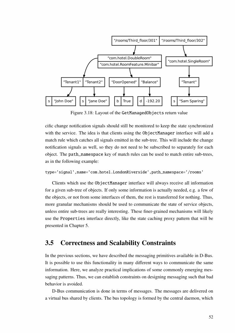
"/rooms/Third_floor/301" "/rooms/Third_floor/302"
"com.hotel.DoubleRoom"
"com.hotel.RoomFeature.Minibar""com.hotel.SingleRoom"
"Tenant1" "Tenant2" "DoorOpened" "Balance" "Tenant"
s "John Doe" s "Jane Doe" b True d -192.20 s "Sam Sparing"
Figure 3.18: Layout of the GetManagedObjects return value
cific change notification signals should still be monitored to keep the state synchronizedwith the service. The idea is that clients using the ObjectManager interface will add amatch rule which catches all signals emitted in the sub-tree. This will include the changenotification signals as well, so they do not need to be subscribed to separately for eachobject. The path_namespace key of match rules can be used to match entire sub-trees,as in the following example:
type=’signal’,name=’com.hotel.LondonRiverside’,path_namespace=’/rooms’
Clients which use the ObjectManager interface will always receive all informationfor a given sub-tree of objects. If only some information is actually needed, e.g. a few ofthe objects, or not from some interfaces of them, the rest is transferred for nothing. Thus,more granular mechanisms should be used to communicate the state of service objects,unless entire sub-trees are really interesting. These finer-grained mechanisms will likelyuse the Properties interface directly, like the state caching proxy pattern that will bepresented in Chapter 5.
3.5 Correctness and Scalability Constraints
In the previous sections, we have described the messaging primitives available in D-Bus.It is possible to use this functionality in many different ways to communicate the sameinformation. Here, we analyze practical implications of some commonly emerging mes-saging patterns. Thus, we can establish constraints on designing messaging such that badbehavior is avoided.
D-Bus communication is done in terms of messages. The messages are delivered ona virtual bus shared by clients. The bus topology is formed by the central daemon, which
52

routes messages between point-to-point connections to each client. Although we use D-Bus as an example case, the conclusions drawn here are applicable to any system whichshares these properties.
3.5.1 Message ordering
D-Bus signals can be used to indicate that an event has occurred. A method return mes-sage indicates that an operation has finished and describes the operation’s outcome. Theeffect and outcome of methods called on objects depends not only on the parameterspassed to them, but also the state the object was in at the time of the call. Some kinds ofstates might be completely unsuitable for invoking a particular operation—namely, thosein which the operation preconditions are not fulfilled (c.f. Section 2.5).
Invoking operations on objects that no longer exist does not make sense. Thus, theobject being alive and well can be considered an implied precondition of all methods. OnD-Bus, one will get an UnknownObject or UnknownMethod error when calling a methodon a nonexistent object [JTM08]. However, this is not always an error on the part of thecaller. Some external event might have caused the object to go away just before the call.On the other hand, calling a method on an object which has never existed is always anerror. However, in terms of the error code returned, that is indistinguishable from theobject having ceased to exist right before the call started processing. It is not feasible forservices to provide more information in the error reply, because to do that they would haveto remember indefinitely which objects have existed at some point in time. This wouldconsume more and more resources as objects are created and destroyed.
D-Bus objects managed by the ObjectManager interface indicate being destroyedthrough the InterfacesRemoved signal, as explained in Section 3.4.5. Thus, it is pos-sible to distinguish the two error cases where the object does not exist by listening tothis signal. If the object did exist, but goes away during a method call, there will be anInterfacesRemoved signal message before the error reply message. If a client receivesand processes the messages in order, it can correctly interpret the error reply as an objecthaving existed, but just now ceased to exist. But if it for some reason processes the replyfirst, it can not distinguish between the two cases.
For a more concrete example, consider a D-Bus object representing a conversationwith multiple participants. Let us assume that current members are able to ”kick” othercurrent members out of the conversations, at which point they cease to be members.This is exactly how e.g. IRC and XMPP multi-user conversations are represented in theTelepathy framework: A RemoveMembers method can be called to kick other members.Kicked members get a MembersChanged signal, the parameters of which indicate thatthey were removed from the set of current members due to being kicked by another
53
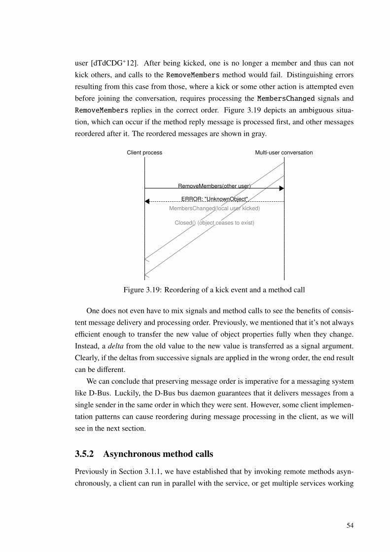
user [dTdCDG+12]. After being kicked, one is no longer a member and thus can notkick others, and calls to the RemoveMembers method would fail. Distinguishing errorsresulting from this case from those, where a kick or some other action is attempted evenbefore joining the conversation, requires processing the MembersChanged signals andRemoveMembers replies in the correct order. Figure 3.19 depicts an ambiguous situa-tion, which can occur if the method reply message is processed first, and other messagesreordered after it. The reordered messages are shown in gray.
Client process Multi-user conversation
MembersChanged(local user kicked)
Closed() (object ceases to exist)
RemoveMembers(other user)
ERROR: "UnknownObject"
Figure 3.19: Reordering of a kick event and a method call
One does not even have to mix signals and method calls to see the benefits of consis-tent message delivery and processing order. Previously, we mentioned that it’s not alwaysefficient enough to transfer the new value of object properties fully when they change.Instead, a delta from the old value to the new value is transferred as a signal argument.Clearly, if the deltas from successive signals are applied in the wrong order, the end resultcan be different.
We can conclude that preserving message order is imperative for a messaging systemlike D-Bus. Luckily, the D-Bus bus daemon guarantees that it delivers messages from asingle sender in the same order in which they were sent. However, some client implemen-tation patterns can cause reordering during message processing in the client, as we willsee in the next section.
3.5.2 Asynchronous method calls
Previously in Section 3.1.1, we have established that by invoking remote methods asyn-chronously, a client can run in parallel with the service, or get multiple services working
54

in parallel. This can increase the total system throughput, i.e. the amount of work ac-complished in a given amount of time.
In addition to throughput, for applications with a graphical user interface (GUI), user-visible latency is also important. The main event loop of GUI applications must be ableto dispatch repainting of the interface 30-60 times per second to maintain smooth anima-tion. Users do not see the total number of frames drawn or the average rate of repaints, butthey can notice if there is a significant delay between successive frames. Thus, nothingmust block the execution of the main loop for significant amounts of time, even occasion-ally [Pen08].
An application can only guarantee that its event loop runs at a consistent pace, if tasksrun by the loop always finish in a shorter time than the maximum allowed interval be-tween user interface repaints. Sending a D-Bus method call message can be done in aknown-short time, as it’s just a matter of sending a small amount of data over the connec-tion to the bus daemon. Similarly, reading a method reply and interpreting it can alwaysbe done fairly quickly. However, the client does not have any guarantees about how longthe service is going to process the method call until it sends the method reply. Both themethod call begin and reply messages can also both end up queued inside the bus daemonfor an indefinite amount of time before they even reach their destination. Thus, either ini-tiating a D-Bus method call or processing the reply for one can be considered acceptablewithin a single iteration of the main loop of an interactive application. However, initiatinga method call, waiting for its result and processing it, all between two successive repaints,can lead to a sluggish user experience.
Despite these suboptimal performance characteristics, real-world D-Bus client librarieslike dbus-glib, dbus-python and QtDBus provide a mechanism to invoke D-Bus meth-ods and block until their result has been received. We will call this mechanism pseudo-
blocking, as in Simon McVittie’s work on the subject [McV08]. The operation of thismechanism is outlined in Algorithm 3.1.
Send method call messageM ← the SERIAL number of the messageloop
Wait until there is a complete message from the bus daemonif the received message has REPLY_SERIAL=M then
return the body of the messageelse
Copy the message to a queue of messages to be processed laterend if
end loop
Algorithm 3.1: D-Bus pseudo-blocking method invocation
55

In addition to slowing down the client main event loop, pseudo-blocking calls havethe potential to completely halt it for a longer period of time. This will occur if theservice process has locked up. In this case, the pseudo-blocking algorithm will loop untila timeout is reached [McV08]. In this way, the effects of programming errors causingdeadlocks can propagate from services onwards to clients.
The pseudo-blocking algorithm has to push aside D-Bus messages other than the oneit is waiting for. Typically, these messages would be processed later, when the applicationresumes running its main event loop. However, this means that these messages will onlybe processed after the method return message [McV08]. As demonstrated in the previoussection, this can cause the return value to be misinterpreted.
Pseudo-blocking calls also have the potential to lock up two otherwise well-behavingprocesses, if they happen to call each other at the same time. Let us call these processesA and B. If A uses the pseudo-blocking algorithm for making the call, it will not processincoming messages, such as method calls from B, until it has received the method replyit is expecting. But if B is doing the same, it will not process the method call A sent, andhence will not reply to it. The D-Bus message exchange for this scenario is presented inFigure 3.20. The two processes are in a cycle waiting for a reply from each other, whichthey will not send because they are reordering incoming method calls after the reply theyare expecting. This puts them in a deadlock. We will call this potential cause of deadlocksa wait-reorder cycle. Note that this kind of symmetric method calling will occur e.g. if Ais using B as a delegatee, and the method call from B is a query for additional informationrequired to complete the operation delegated to it (c.f. Section 2.3 on delegation).
Process A Process B
METHOD_CALL serial=1
METHOD_CALL serial=2
A and B will be stuck here waiting for each other, if they use pseudo-blocking
METHOD_REPLY reply_serial=2
METHOD_REPLY reply_serial=1
Figure 3.20: Simultaneous method call between two processes
It is possible to break the wait-reorder cycle by making either A or B call the otherend asynchronously. If A just starts the method call and then resumes running its mainevent loop, it is able to process other events, such as incoming method calls from B. Thereply to the method will be just another event handled by A’s main loop. It is not easyto predict when implementing A, if asynchronous behavior will be needed. It is onlysafe to make a pseudo-blocking method call to B, if it is known that B will never make a
56

similar call back to A at the same time. In theory, if B is just a D-Bus service, and nevermakes outgoing method calls, it can not participate in a wait-reorder cycle. However,the implementation of B may change over time. If B has a plug-in system, a plug-inmight end up making pseudo-blocking method calls, although the core B application itselfwould not. If the plug-ins run in the parent application’s main loop, they can stall theparent [McV08]. We have seen deadlocks caused by plugins that make pseudo-blockingcalls in the development of both One Laptop per Child and Nokia mobile device operatingsystems.
Changing pseudo-blocking code to be fully asynchronous is not trivial. It requiresrewriting almost from scratch the parts of the application that invoke remote methodsusing D-Bus [Pen08]. This is because with pseudo-blocking calls, the result of the remotemethod can be utilized right after the call, e.g. by showing it to the user. This is helpful,because the context that led to invoking the remote method is still reachable, and it canbe used to decide what the result should be used for. Algorithm 3.2 presents the basicstructure of code that makes a single pseudo-blocking method call and utilizes its result.Algorithms 3.3 and 3.4 show similar asynchronous code for comparison. Notably, thealgorithm needs to be split to a part which starts the call and to a part which finishes itand utilizes the result. Context needs to be explicitly transferred between the two halvesof the algorithm. Because of this significant difficulty of changing pseudo-blocking callsto asynchronous ones, we argue that all code should be written to be fully asynchronousfrom the beginning.
Do local processingR← Result of pseudo-blocking D-Bus method call to BUse the result R for more processingreturn to main event loop
Algorithm 3.2: Code that utilizes pseudo-blocking calls
Do local processingStart an asynchronous D-Bus method call to BSet Algorithm 3.4 to be invoked when the reply is receivedSave local context so that the processing can continue laterreturn to main event loop
Algorithm 3.3: Code that invokes a service asynchronously
Re-entrant pseudo-blocking
Some D-Bus client libraries provide a re-entrant variant of the pseudo-blocking mecha-nism. An example of this is the QDBus::BlockWithGui call mode of the QDBus library.
57

R← Newly received D-Bus method resultResume saved context for the operationUse the result R for more processingreturn to main event loop
Algorithm 3.4: Code that utilizes the asynchronously received result
In this variant, instead of pushing messages other than the desired reply to a queue, theyare processed like the main loop was running again [McV08]. Hence the name—the mainloop is effectively re-entered for the duration of the call. Switching to this mode mightseem like an appealing alternative to changing code to be properly asynchronous, becauseit will provide the method result to the caller immediately, just like pseudo-blocking calls.However, as the messages are processed directly, not through a queue, the message re-ordering and deadlock drawbacks of classic pseudo-blocking are not present.
Let us recall the concept of class invariant from Section 2.5. The class invariant isa condition that must always hold in an object of a class unless a method has currently
been invoked on it. Typically, class methods have restored the invariant by the time theyreturn, but it might not hold at all times during their execution. Now, if an object makesre-entrant blocking calls in one of its methods, it might have to process other method callson itself as a part of the re-entrant event processing. These method calls expect that theclass invariant holds. Thus, even though the original method has not returned to the mainloop, it has to have restored the class invariant. This is much less obvious than the needto carry state between the two halves of an asynchronous algorithm, and can be harderor even outright impossible to accomplish. Thus, we consider re-entrant pseudo-blockingbehavior to be too unpredictable, and hence something that should be avoided.
3.5.3 Message granularity
For a D-Bus message to get delivered from a process to another one, many steps needto happen. First, the message is encoded to the wire format. Then, it is sent over theconnection to the bus daemon. The bus daemon uses the information in the messageheader to decide which processes to deliver the message to. The message is sent to thereceivers through the connections to them. Finally, the receiving process(es) decode themessage from the wire format and process it.
It is notable that all messages pass through the bus daemon process on their way fromone process to another. This requires a context switch to the bus daemon, and further onesto the receiving processes. Additionally, at least in Linux, the network traffic between theprocesses on the bus and the bus daemon causes a context switch to the operating systemkernel, because the kernel transfers the data between the processes. Figure 3.21 depicts
58

the minimum context switches needed to transfer a D-Bus message from its sender to asingle receiver in this kind of a system.
The same context switches are needed for messages of any size. Large D-Bus mes-sages do not take significantly more time than small ones to transfer [Cre08]. This isconsistent with practical results from older IPC systems (e.g. [BN84]). It can be inferred,that context switch overhead dominates the time required for message transfer, and thetime taken to actually send the message payload on the wire has less of an effect.
Sender Bus daemon
Operating system kernel
Receiver
Figure 3.21: Context switches during D-Bus message delivery
By packing more data in a single message, more throughput can be attained, becausegreater amounts of useful data is transferred between each context switch. It has beenfound that messages with several dozens of kilobytes of payload give around four timesmore throughput than messages with 1kB payload, which in turn yield several magni-tudes of throughput more than small messages of only a few bytes each. However, mostmessages in real-world usage of D-Bus fall in the size range from dozens to hundreds ofbytes [Tho11]. Thus, it should be made a priority for messaging design to always strivefor the largest message size possible. This can be achieved by batching related actionsand events together. This done e.g. in the initialization of objects following our D-Busproxy pattern, which will be proposed in Chapter 5.
59
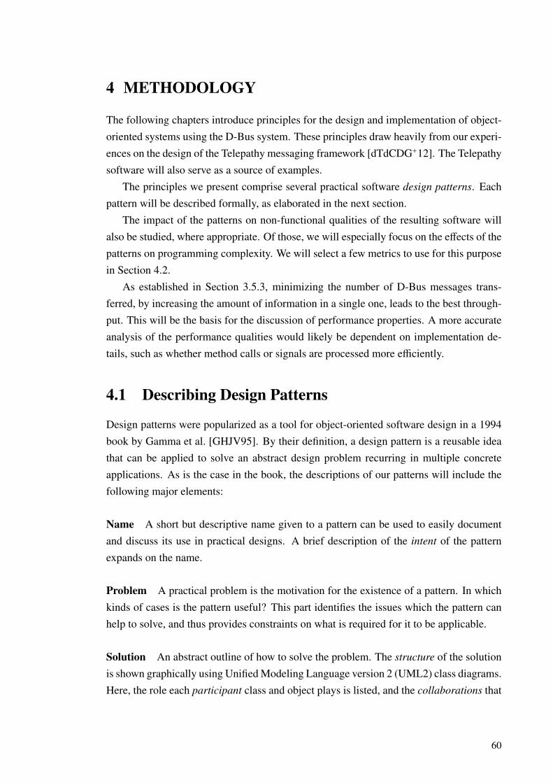
4 METHODOLOGY
The following chapters introduce principles for the design and implementation of object-oriented systems using the D-Bus system. These principles draw heavily from our experi-ences on the design of the Telepathy messaging framework [dTdCDG+12]. The Telepathysoftware will also serve as a source of examples.
The principles we present comprise several practical software design patterns. Eachpattern will be described formally, as elaborated in the next section.
The impact of the patterns on non-functional qualities of the resulting software willalso be studied, where appropriate. Of those, we will especially focus on the effects of thepatterns on programming complexity. We will select a few metrics to use for this purposein Section 4.2.
As established in Section 3.5.3, minimizing the number of D-Bus messages trans-ferred, by increasing the amount of information in a single one, leads to the best through-put. This will be the basis for the discussion of performance properties. A more accurateanalysis of the performance qualities would likely be dependent on implementation de-tails, such as whether method calls or signals are processed more efficiently.
4.1 Describing Design Patterns
Design patterns were popularized as a tool for object-oriented software design in a 1994book by Gamma et al. [GHJV95]. By their definition, a design pattern is a reusable ideathat can be applied to solve an abstract design problem recurring in multiple concreteapplications. As is the case in the book, the descriptions of our patterns will include thefollowing major elements:
Name A short but descriptive name given to a pattern can be used to easily documentand discuss its use in practical designs. A brief description of the intent of the patternexpands on the name.
Problem A practical problem is the motivation for the existence of a pattern. In whichkinds of cases is the pattern useful? This part identifies the issues which the pattern canhelp to solve, and thus provides constraints on what is required for it to be applicable.
Solution An abstract outline of how to solve the problem. The structure of the solutionis shown graphically using Unified Modeling Language version 2 (UML2) class diagrams.Here, the role each participant class and object plays is listed, and the collaborations that
60

occur between them are described. As the intent is for the solution to be general, thesedescriptions need to be filled out with application-specific details such as class names toproduce concrete designs. We will mention examples of such concrete known uses of thepatterns to further illustrate how they solve practical problems.
Consequences How will the use of the pattern affect the properties of the resultingdesign? Here, we will describe the tradeoffs inherent to the use of the pattern, in areassuch as performance, complexity and flexibility. The consequences can be crucial whenchoosing between multiple design alternatives.
As an example of this pattern description format in action, we will now describe theclassic Factory pattern from the Gamma et al. book [GHJV95]. A specialized version ofthis particular pattern will also be presented in Section 5.4.
Example pattern: Abstract Factory
Intent Make it possible to create objects that implement a given interface without spec-ifying their concrete class, so that the concrete classes can be substituted as needed.
Problem A central motivation behind class inheritance is to allow specializations of agiven base class to be treated uniformly. For example, a text field user interface elementmight be a base class, and be specialized for different user interface toolkits. A componentthat sets the contents of a text field can do so using the generic interface of the base class.However, when creating an object, to attain correctly specialized behavior, a specializedsubclass instance needs to be created. If the instance is created directly, the exact subclasswill be hard-coded and can not be changed without modifying the creator component.
Participants
• The abstract base class which declares the common interface for objects created bythe factory. This is the TextField class in the example depicted by Figure 4.1.
• Derived classes which provide specialized behavior for the interface. In the exam-ple, these are the GtkTextField and QtTextField classes.
• Abstract base class for factories that create objects which implement the interface.
• Specialized factory subclasses, which create corresponding derived class instances.The GtkWidgetFactory and QtWidgetFactory specialize the WidgetFactorybase class in the example, to create their own types of text field objects.
61

Collaboration Instead of constructing objects directly, methods of the abstract factoryinterface are used to create object instances. The factory subclass determines the con-crete class of the object produced. A factory can produce just one kind of objects, as inFigure 4.1, or a family of related kinds of objects.
TextField+contents
+paint()
GtkTextField+paint()
QtTextField+paint()
WidgetFactory+createTextField(): TextField
GtkWidgetFactory+createTextField(): GtkTextField
QtWidgetFactory+createTextField(): QtTextField
Figure 4.1: Structure of the Abstract Factory pattern
Consequences Code creating objects is decoupled from their concrete classes. Thismakes it easy to specialize behavior later by just replacing the factory with one that pro-duces objects of a different concrete class. The factory adds a level of indirection to objectcreation, which can incur a slight performance overhead.
4.2 Predicting Programming Complexity
The complexity of a programming interface affects how easy it is to understand. Un-derstanding an interface is a precursor to using it correctly [GG04]. Hence, to maximizereusability of software components, the complexity of their interfaces should be kept min-imal [BA04].
Gill and Grover proposed a metric [GG04] for measuring the complexity of compo-nent interfaces. The value of this metric is a weighted sum of three factors:
IC = aCs + bCc + cCg ,
where Cs is determined by the signature complexity of the interface, Cc by the interface
62

constraints and Cg by the interface configurations. a, b and c are suitable weights, to bedetermined empirically.
The signature complexity comes from the number of operations and events in theinterface:
Cs = a1no + b1ne ,
where no and ne are the total number of operations and events in the interface. Propertiesare also considered to be a part of the interface signature, but they are not included in themetric - presumably because accessing them is fairly trivial in non-distributed applica-tions.
Boxall and Araban argue [BA04] that the sheer size of an interface is an unreliableindicator of its understandability and reusability. This is because larger interfaces implymore functionality, and hence possibly being useful for more purposes. Instead, theyfocus on the number of arguments the interface members have on average. The logic isthat procedures with fewer arguments are easier to understand, and thus to reuse. Thesame reasoning can be extended to events. We can formulate this metric for methods andevents commonly as arguments per member (APM), given by
APM =na
no + ne,
where na is the total number of arguments in all methods and events on the interface, andno and ne are as before.
The constraint factor Cc of Gill and Grover’s metric comes from the rules on how theinterface can be used. The pre- and postconditions for interface methods (see Section 2.5)increase this value. Contracts that are subjectively harder to fulfill have a larger impact.Another kind of contribution to the constraint factor may come from dependencies be-tween property values, if they can be set to illegal combinations.
The final factor Cg comes from the fact that when a given component is used in multi-ple kinds of scenarios, it will be configured differently. It might interact with other com-ponents in a different fashion, or different parts of its interface may be used. An interfacethat functions in a similar fashion in all its use scenarios will have a lower configurationcomplexity.
Boxall and Araban also provide multiple metrics for measuring the consistency ofan interface. The rationale is that a more consistent interface is easier to learn, becauseknowledge of a single part of it can be transferred to using other parts. These metricsare mostly concerned with low-level details such as argument naming, and so are notapplicable for our pattern-level analysis. However, we will use the basic assumption thatconsistency lowers complexity in other ways.
63

Gill and Grover also mention that non-functional qualities such as security, perfor-mance and reliability affect reusability. This is because these qualities propagate to anapplication that uses the component. No formula to produce an aggregate numeric valuefor these qualities is provided, however. Rather, deficiencies in these areas may rule outreusing a component altogether in a particular application, no matter how simple its inter-face would be.
These metrics can not be applied in their original form to distributed software. This isbecause they lack the notion of asynchronous method calls. As explained in Section 3.5.2,placing an asynchronous call necessitates saving the state of the local computation andresuming it in a second method, to be executed once the call completes. Thus, the com-plexity contributed by an asynchronous method can be thought to be at least twice that ofa synchronous one, and possibly more, depending on the difficulty of saving and restoringthe state. This means that asynchronous operations are a major contribution to the com-plexity of remote object access interfaces. This conclusion matches practice—we havediscovered asynchronicity to be a major programming challenge.
Interface properties need similar special treatment. The properties forming the state oflocal objects can be inspected easily by calling a synchronous getter method, usually withno arguments. This kind of method can be considered very simple. However, inspectingthe value of a remote object property requires invoking the getter remotely. To avoid theproblems described in Section 3.5.2, this call also needs to be asynchronous. Thus, unlessspecial measures are taken, properties also need to be considered fairly complex in thedistributed setting.
The exact numerical values of the metrics depend on empirically assigned weights,and will not be comparable between different kinds of components and application ar-eas [GG04]. As we will attempt to come up with generic solution patterns, we will ac-cordingly analyze the trends and asymptotic behavior of the metrics rather than their exactvalues.
64

5 DESIGNING D-BUS CLIENT APPLICATIONS
In the previous chapters, we have explored concepts of object-oriented software, the struc-ture of distributed systems in general, and the properties of the D-Bus system in particular.Now, we will describe some mechanisms we have found useful when building object-oriented systems with D-Bus. These mechanisms have been developed in the contextof the Telepathy real-time communication framework, but they are general enough to besuitable for other application areas as well. Generic implementations of some of the con-structs in fact already exist, for example in the GDBus library [Zeu12].
The bulk of the functionality of a distributed system is implemented in its servicecomponents. However, this functionality is only exposed to users by the frontend compo-nents. Frontends, especially those with a graphical user interface (GUI), tend to be tied tospecific environments more than the backends are. As an example, we have been able toshare the protocol backends and account management infrastructure of Telepathy betweenthe GNOME and KDE desktops and various mobile devices. However, most GUI com-ponents have been reimplemented for each of these environments. This motivates us tomake it as easy as possible for such components (clients) to access the services, while stillobeying the constraints for messaging design (see Section 3.5). This ensures maximumreusability.
To accommodate convenient access to the services, we have implemented a set ofclient libraries for Telepathy. The Telepathy-Qt library [SMM12] is used by the KDEdesktop and Nokia N9 phone frontend software, and the telepathy-glib library [AAB+12]e.g. in the GNOME desktop. These libraries mainly consist of proxy objects that mirrorinteresting service objects in client address space. D-Bus connects the clients and servicestogether. However, the proxy objects hide the actual D-Bus communication behind afriendly programming interface. The following sections detail the design of the proxiesand how their communication needs are implemented with D-Bus primitives. Besidesproxies, some related helpful constructs will also be described.
The structure of client libraries has to closely follow the design of the underlyingD-Bus interfaces, which the service objects implement. However, the only purpose ofexporting objects over D-Bus is to allow clients to access them. Thus, we see D-Bus in-terface design as just a tool to make client libraries as convenient and efficient as possible.Accordingly, the following sections will also touch subjects in interface design.
65

5.1 Pending Operation Objects
Proxy objects are just representatives of the real objects that reside in service addressspace. Thus, they need to make D-Bus method calls to the service to implement a lotof their functionality. These calls must be made asynchronously, because otherwise theuse of the proxies would incur the drawbacks of synchronous calls, as described in Sec-tion 3.5.2. Concretely, this means that in proxies, no operation that may potentially calla service with D-Bus can wait for the call to complete before returning to its own caller.This implies that the outcome of the D-Bus operation needs to be reported to the callervia some other mechanism, after the proxy operation has returned.
In Section 3.1.1, we mentioned the concepts of promise and future objects. Thesekinds of objects represent the result of an asynchronous computation. When the com-putation is finished, the result can be extracted from them. The objects support pollingto check whether the result is available already, and waiting for it to become available.However, they were designed for performing distributed calculations. In that context, therationale for making remote operation invocation asynchronous is to make it possible tostart multiple operations in parallel, and/or do local processing while a remote calculationis executing. In either case, the caller will have a definite point in its execution, at which ithas nothing else to do until it gets the results. At that point, it will wait for the results to be-come ready and then continue processing with them. This is unlike applications that mustremain responsive to user input, have a GUI to animate, or need to serve inter-processmethod calls themselves. They never have such an opportunity to start waiting for results.On the other hand, periodic polling for the result to be available would be wasteful, andwould add latency, up to the polling interval, before the result gets processed.
To avoid both blocking to wait for results and wasteful polling, an event (Section 2.7)can be announced to indicate that a previously started operation has finished. The resultscan be processed in a handler for the event. This can happen as soon as the applicationhas no other work to do, with no added latency.
It is usually necessary to know to which invocation of an operation results belong,in order to correctly interpret them. Thus, the operation completion events must includesome reference to the particular invocation. One approach is to assign an opaque opera-
tion identifier to started operations, and to include this value later in the arguments of thecorresponding event. This is analogous to low-level D-Bus messages, which include a se-rial number, and where reply messages specify the serial of the message they correspondto. However, the need to communicate the operation identifier increases the complexityof the event’s signature, which shows as an increase in the value of the arguments per
member metric.
66

In Telepathy-Qt, running asynchronous operations are represented as objects. Theseobjects are instances of classes derived from the PendingOperation base class. Noseparate operation identifiers are employed—the object identity implicitly determinesthe corresponding operation invocation. The PendingOperation interface includes anevent that indicates that the operation has finished, and methods to check whether it fin-ished successfully, or if an error occurred. This information is common to all opera-tions, unlike the type of a result produced for a successful invocation. Subclasses suchas PendingAccount and PendingConnection exist, roughly corresponding to each re-sult type. The subclasses add methods to inspect the value of the result. Using a singlebase class to represent the common information gives a lower total number of operationsand events, which reduces total signature complexity. It also makes the way of signalingoperation completion consistent between all operations.
Sometimes, a client requires multiple operations to finish before it can continue. Oftenin these cases, the operations do not depend on results from each other, and so they canbe started independently. Telepathy-Qt includes the PendingComposite class, whichmakes it easy to wait for a set of concurrently started operations to finish. In a way, this issimilar to the futures mechanism that was mentioned in Section 3.1.1, but applied to thecontext of event-driven desktop software.
We will now generalize the scheme of representing asynchronous operations as objectsin the Telepathy-Qt library, as a formal design pattern. This will be followed by a similardescription of the aggregation mechanism that is implemented by the PendingCompositeclass.
Pattern: Pending Operation Objects
Intent Provide a consistent way to deliver asynchronous operation results once avail-able, without blocking and/or polling.
Problem Interactive applications can never stall their event processing for indefiniteamounts of time. Results that take an unbounded amount of time to be produced musttherefore be processed asynchronously. Result availability can be announced as an event,but there needs to be a way to associate the results in the event with the original request, inorder to correctly interpret them. Adding these events and mechanisms to associate resultswith requests to a programming interface can increase its complexity if done naively.
Participants
• The base class for all pending operation objects, which includes the common at-
67

tributes and the event that is used to signal the completion of the operation. Thisis the PendingOperation class in the Telepathy-Qt library, and in the example inFigure 5.1.
• Derived classes for each type of operation result. These make it possible to retrievethe value of the result in an appropriate form. In the example figure, these would bePendingAccount and PendingConnection.
• Classes that need to have asynchronous operations, such as proxies for D-Bus ob-jects. These create and return the pending operation object instances when an asyn-chronous operation is started on them. AccountManager and Account are theclasses with this role in the example.
Collaborations Results for asynchronous operation invocations are delivered by havingan event announced on the corresponding pending operation object. Client code extractsthe values of results using methods declared in the result type specific subclasses. Thecomplete structure of the solution is illustrated in Figure 5.1, with the class names corre-sponding to those in the Telepathy-Qt library.
AccountManager+createAccount(): PendingAccount
Proxy
Account+connect(): PendingConnection
PendingOperation+isFinished+error
+<<event>> finished()
PendingAccount+account: Account
PendingConnection+connection: Connection
creates
creates
returns
Figure 5.1: Structure of the Pending Operation Objects pattern
Consequences Completion of all asynchronous operations is signaled in a uniform way.This avoids having to re-learn how completion is indicated for each operation, and there-
68
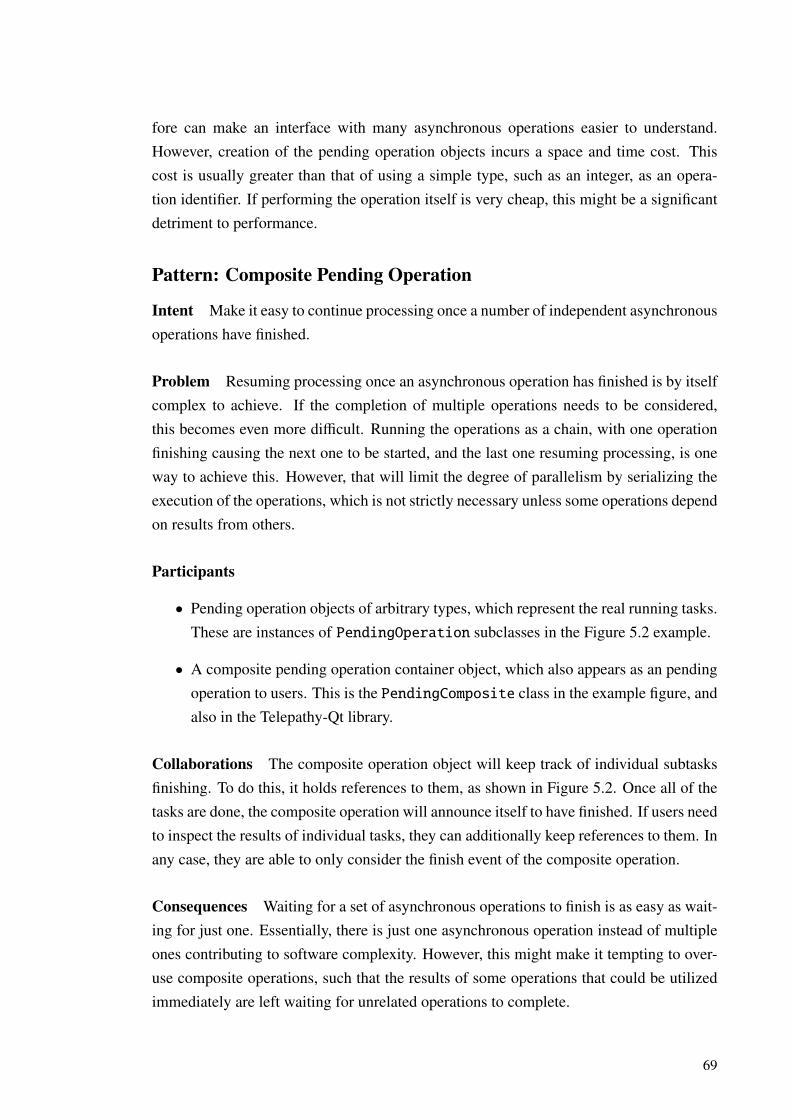
fore can make an interface with many asynchronous operations easier to understand.However, creation of the pending operation objects incurs a space and time cost. Thiscost is usually greater than that of using a simple type, such as an integer, as an opera-tion identifier. If performing the operation itself is very cheap, this might be a significantdetriment to performance.
Pattern: Composite Pending Operation
Intent Make it easy to continue processing once a number of independent asynchronousoperations have finished.
Problem Resuming processing once an asynchronous operation has finished is by itselfcomplex to achieve. If the completion of multiple operations needs to be considered,this becomes even more difficult. Running the operations as a chain, with one operationfinishing causing the next one to be started, and the last one resuming processing, is oneway to achieve this. However, that will limit the degree of parallelism by serializing theexecution of the operations, which is not strictly necessary unless some operations dependon results from others.
Participants
• Pending operation objects of arbitrary types, which represent the real running tasks.These are instances of PendingOperation subclasses in the Figure 5.2 example.
• A composite pending operation container object, which also appears as an pendingoperation to users. This is the PendingComposite class in the example figure, andalso in the Telepathy-Qt library.
Collaborations The composite operation object will keep track of individual subtasksfinishing. To do this, it holds references to them, as shown in Figure 5.2. Once all of thetasks are done, the composite operation will announce itself to have finished. If users needto inspect the results of individual tasks, they can additionally keep references to them. Inany case, they are able to only consider the finish event of the composite operation.
Consequences Waiting for a set of asynchronous operations to finish is as easy as wait-ing for just one. Essentially, there is just one asynchronous operation instead of multipleones contributing to software complexity. However, this might make it tempting to over-use composite operations, such that the results of some operations that could be utilizedimmediately are left waiting for unrelated operations to complete.
69
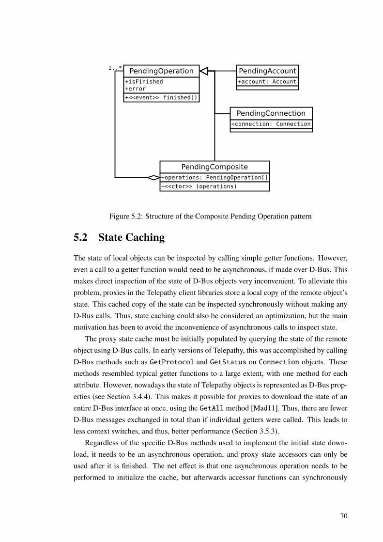
PendingOperation+isFinished+error
+<<event>> finished()
PendingAccount+account: Account
PendingConnection+connection: Connection
PendingComposite+operations: PendingOperation[]
+<<ctor>> (operations)
1..*
Figure 5.2: Structure of the Composite Pending Operation pattern
5.2 State Caching
The state of local objects can be inspected by calling simple getter functions. However,even a call to a getter function would need to be asynchronous, if made over D-Bus. Thismakes direct inspection of the state of D-Bus objects very inconvenient. To alleviate thisproblem, proxies in the Telepathy client libraries store a local copy of the remote object’sstate. This cached copy of the state can be inspected synchronously without making anyD-Bus calls. Thus, state caching could also be considered an optimization, but the mainmotivation has been to avoid the inconvenience of asynchronous calls to inspect state.
The proxy state cache must be initially populated by querying the state of the remoteobject using D-Bus calls. In early versions of Telepathy, this was accomplished by callingD-Bus methods such as GetProtocol and GetStatus on Connection objects. Thesemethods resembled typical getter functions to a large extent, with one method for eachattribute. However, nowadays the state of Telepathy objects is represented as D-Bus prop-erties (see Section 3.4.4). This makes it possible for proxies to download the state of anentire D-Bus interface at once, using the GetAll method [Mad11]. Thus, there are fewerD-Bus messages exchanged in total than if individual getters were called. This leads toless context switches, and thus, better performance (Section 3.5.3).
Regardless of the specific D-Bus methods used to implement the initial state down-load, it needs to be an asynchronous operation, and proxy state accessors can only beused after it is finished. The net effect is that one asynchronous operation needs to beperformed to initialize the cache, but afterwards accessor functions can synchronously
70

return cached values. In proxies for objects with multiple state properties, this reducesthe interface signature complexity contributed by asynchronous operations. However, thepreconditions of the accessor functions simultaneously become more complex, as theyrequire the state download to have been successfully performed. In Telepathy-Qt proxies,the becomeReady() method starts the state download. The telepathy-glib counterpart isthe tp_proxy_prepare_async() function.
The initial state download only captures the state of the remote object at a certainpoint of time. If the state changes, the local state copy needs to be updated. Otherwisethe values returned by state accessors would get out of date. To keep the state cacheup to date, proxies can subscribe to change notification events from their remote object.Starting the state download also causes Telepathy proxies to subscribe to the appropriatechange notification events. Note that state updates are only propagated to proxy objectswhen the change notification events reach them. Thus, the service objects and proxies arenot always perfectly synchronized. This has seldom been found to be a problem, however,and the same kind of delay applies to naively invoking the getter functions over D-Bus.
The PropertiesChanged D-Bus signal is a suitable way to implement change notifi-cation for most D-Bus properties. However, the design of most parts of Telepathy predatesthe addition of this signal to the D-Bus specification. For that reason, custom change no-tification signals exist in many interfaces, such as StatusChanged in the Connectioninterface. As explained before, the PropertiesChanged signal is not well suited forannouncing changes to properties that have values of a very large size, if the change justaffects a small part of the value. Reporting the changes incrementally is more appropri-ate for such properties. A proxy can be programmed to apply incremental changes to acached property values to derive the new values.
If D-Bus properties and PropertiesChanged change notification are used to rep-resent state of D-Bus objects, it is straightforward to implement state caching. This isbecause subscribing to PropertiesChanged and calling GetAll is all that is needed.No interface-specific knowledge is needed on facts such as which getter functions to calland how to interpret custom change notification signals. The GDBusProxy class in theGDBus library caches property values in a generic fashion.
When the remote object disappears, values in the state cache lose their meaning. Sim-ilarly, operations can no longer be invoked on the object. At this point, Telepathy proxiesconsider themselves invalidated. This might result from normal events such as closingcommunication sessions (e.g. hanging up a call), or faults such as the backend processhaving crashed. The exact conditions that cause invalidation depend on the proxy. Typi-cally, they at least watch for NameOwnerChanged signals (see Section 3.4.3) to catch theprocess hosting the remote object disappearing from the bus.
71

The example in Figure 5.3 illustrates in a simplified form, how the state caching fa-cility of Telepathy-Qt Connection proxies works. The state of Telepathy Connectionobjects includes information such as whether the connection is still in the process of es-tablishing a connection to the service, or if that is already done. After the asynchronousinitialization operation, client code can query the proxy for the state synchronously. Thestate queries do not require any D-Bus calls to be made. As the asynchronous initializa-tion operation includes subscribing to change notification signals, the proxy state is keptup-to-date through service state changes. Finally, the proxy object invalidates itself whenthe connection is disconnected.
Some parts of object state retain the same value for the lifetime of the object. If thisis always the case for a certain state property, it does not need change notification. Wewill call such properties immutable. If the value of an immutable property is in some wayknown previously, it does not need to be rediscovered when initializing the state cacheof a proxy, as it can not have changed in the meantime. For example, Channel objectsin Telepathy represent active communication sessions, such as text chats and video calls.The properties in the main Channel interface describe what kind of a session the Channelrepresents—whether it was initiated by the local user or a remote one, whether there isa group of peers or just one, and so on. All of these properties in the Channel interfaceare immutable. When the creation of a new Channel is announced, the values of theimmutable properties are included in the signal arguments. This makes it possible forTelepathy proxies to skip the GetAll call for properties on Channel and other similarinterfaces. Instead, they can initialize the state cache with the values from the creationsignal. This optimization is currently not possible with the generic state caching facilityof GDBus proxies.
Next, we will give a formal description of the above proxy state caching mechanism.The example case in this description is a simplified form of the corresponding parts of theTelepathy-Qt library.
Pattern: State Caching Proxy
Intent Allow inspecting the state of remote objects synchronously, without hitting theusual problems associated with synchronous D-Bus calls.
Problem Inspecting the state is a common operation in the use of many kinds of objects.That is needed e.g. to present information from an object to the user, or to decide whethersome operation could be invoked on the object. The state of local objects can be inspectedby calling simple getter methods. However, when an object is accessed over D-Bus,invoking getter methods is not as simple. Synchronous calls to them could block the
72
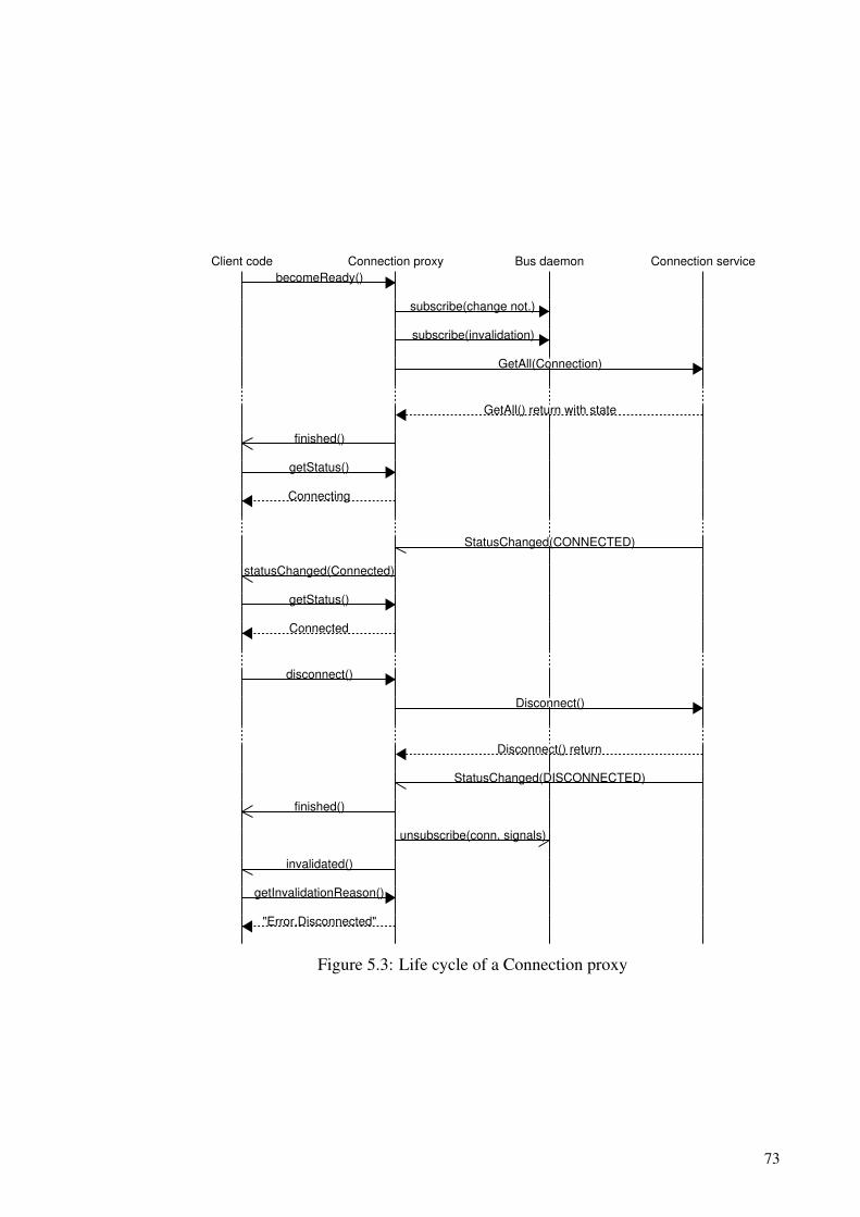
Client code Connection proxy Bus daemon Connection service
becomeReady()
subscribe(change not.)
subscribe(invalidation)
GetAll(Connection)
GetAll() return with state
finished()
getStatus()
Connecting
StatusChanged(CONNECTED)
statusChanged(Connected)
getStatus()
Connected
disconnect()
Disconnect()
Disconnect() return
StatusChanged(DISCONNECTED)
finished()
unsubscribe(conn. signals)
invalidated()
getInvalidationReason()
"Error.Disconnected"
Figure 5.3: Life cycle of a Connection proxy
73
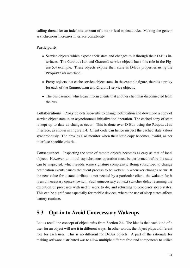
calling thread for an indefinite amount of time or lead to deadlocks. Making the gettersasynchronous increases interface complexity.
Participants
• Service objects which expose their state and changes to it through their D-Bus in-terfaces. The Connection and Channel service objects have this role in the Fig-ure 5.4 example. These objects expose their state as D-Bus properties using theProperties interface.
• Proxy objects that cache service object state. In the example figure, there is a proxyfor each of the Connection and Channel service objects.
• The bus daemon, which can inform clients that another client has disconnected fromthe bus.
Collaborations Proxy objects subscribe to change notification and download a copy ofservice object state in an asynchronous initialization operation. The cached copy of stateis kept up to date as changes occur. This is done over D-Bus using the Propertiesinterface, as shown in Figure 5.4. Client code can hence inspect the cached state valuessynchronously. The proxies also monitor when their state copy becomes invalid, as perinterface-specific criteria.
Consequences Inspecting the state of remote objects becomes as easy as that of localobjects. However, an initial asynchronous operation must be performed before the statecan be inspected, which readds some signature complexity. Being subscribed to changenotification events causes the client process to be woken up whenever changes occur. Ifthe new value for a state attribute is not needed by a particular client, the wakeup for itis an unnecessary context switch. Such unnecessary context switches delay resuming theexecution of processes with useful work to do, and returning to processor sleep states.This can be significant especially for mobile devices, where the use of sleep states affectsbattery runtime.
5.3 Opt-in to Avoid Unnecessary Wakeups
Let us recall the concept of object roles from Section 2.4. The idea is that each kind of auser for an object will use it in different ways. In other words, the object plays a differentrole for each user. This is no different for D-Bus objects. A part of the rationale formaking software distributed was to allow multiple different frontend components to utilize
74

<<service object>>
Connection+Protocol+Status
+<<event>> StatusChanged(newStatus)+<<event>> NewChannel(objectPath, immutableProperties)+<<event>> Disconnected()
<<D-Bus interface>>
Properties+Get(property)+Set(property,value)+GetAll()+<<event>> PropertiesChanged(changed,invalidated)
<<service object>>
Channel+ChannelType+RequestedLocally+TargetID+InitiatorID
+<<event>> Closed()+Close()
Proxy+isReady+isValid+invalidationReason
+becomeReady(): PendingOperation+<<event>> invalidated(reason)
<<proxy>>
Connection+protocol+status
+<<event>> statusChanged(newStatus)+<<event>> newChannel(channel:Channel)
<<proxy>>
Channel+channelType+requestedLocally+targetID+initiatorID
+close(): PendingOperation
D-Bus
Figure 5.4: Structure of the State Caching Proxy pattern
75

services from a backend at once. The exact set of functionality employed will naturallybe different for each frontend. It follows that if proxies expose all of the functionality ofa service object to all clients, some of it will be redundant.
Offering redundant functionality is not a problem in itself. However, because keepinga proxy’s state cache up to date necessitates subscribing to change notification events,caching unneeded pieces of state causes unnecessary wakeups. As noted in the previoussection, this can be detrimental to performance and power usage.
The harmful effects of proxying unneeded functionality is not limited to wakeups forchange notification. D-Bus signals are used for announcing other kinds of events than juststate changes. These events are relayed by proxies to the client in a suitable form. If someevents are not interesting, the wakeups caused by them will also be unnecessary. Addi-tionally, many proxies in Telepathy client libraries aggregate information from multipleD-Bus interfaces implemented by service objects. This is done to provide a more naturalprogramming interface. However, if the state of a particular interface is not needed at all,the GetAllmethod call to fetch it will be wasted, increasing both D-Bus traffic and proxyinitialization latency for no reason.
To solve this, some functionality of Telepathy proxies is conditionally enabled. Theseindividual subsets of functionality are called the optional features of the proxies. Forexample, proxies for text chat objects report the unread messages in the chat. This func-tionality is likely needed by anything observing a text chat session. However, there is alsosupport to report the active state of the chat—whether the remote user is currently typing,is inactive, and so forth. This information can be instantly displayed to a user. However,it makes little sense to permanently store the chat state in a log, as it is transient by nature.Accordingly, both a user interface (UI) application for text chatting and a daemon thatlogs conversations to permanent storage would utilize the message buffer, but only the UIapplication would enable the feature that causes typing notifications to be delivered.
The features can be individually enabled, or multiple features can be activated in a sin-gle asynchronous operation. The corresponding signal subscriptions and state downloadwill be performed behind the scenes by the proxy. Note that this depends on the capabilityto dynamically subscribe to the change notification signals, and thus the dynamic natureof D-Bus match rules.
Features further increase the complexity imposed by the asynchronous initializationof proxies: availability of proxy functionality is no longer just a matter of whether aproxy has been prepared for use, but also whether suitable features have been requestedwhile doing so. We will consider these effects as a part of the following formal patterndescription.
76
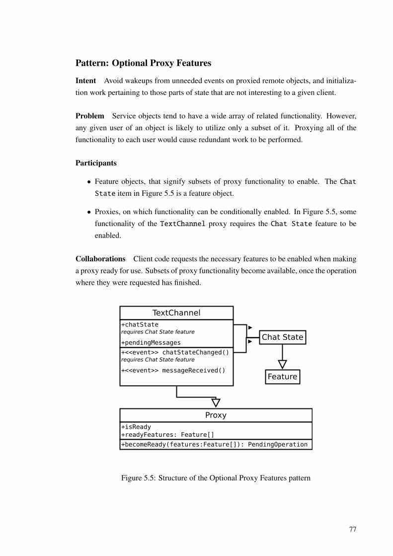
Pattern: Optional Proxy Features
Intent Avoid wakeups from unneeded events on proxied remote objects, and initializa-tion work pertaining to those parts of state that are not interesting to a given client.
Problem Service objects tend to have a wide array of related functionality. However,any given user of an object is likely to utilize only a subset of it. Proxying all of thefunctionality to each user would cause redundant work to be performed.
Participants
• Feature objects, that signify subsets of proxy functionality to enable. The ChatState item in Figure 5.5 is a feature object.
• Proxies, on which functionality can be conditionally enabled. In Figure 5.5, somefunctionality of the TextChannel proxy requires the Chat State feature to beenabled.
Collaborations Client code requests the necessary features to be enabled when makinga proxy ready for use. Subsets of proxy functionality become available, once the operationwhere they were requested has finished.
Proxy+isReady+readyFeatures: Feature[]
+becomeReady(features:Feature[]): PendingOperation
TextChannel+chatStaterequires Chat State feature
+pendingMessages
+<<event>> chatStateChanged()requires Chat State feature
+<<event>> messageReceived()Feature
Chat State
Figure 5.5: Structure of the Optional Proxy Features pattern
77

Consequences When proxy functionality is carefully divided to features, redundantwork to offer unneeded functionality can be avoided. However, the preconditions of theconditionally enabled proxy members become more complex as a result. This can also beseen to increase the configuration complexity factor of Gill and Grover’s interface com-plexity metric (see Section 4.2). This is because client code may need to prepare to useproxy objects with multiple configurations of features enabled. Cautious measures to pre-vent this might include enabling more features than is actually needed, which defeats thepurpose of optional proxy features.
5.4 Asynchronous Proxy Factories
Not all Telepathy proxy instances are created directly by application code. Some of themare created by other proxies and other client library components. For example, Telepa-thy Account objects store information such as credentials, server addresses, etc. that isnecessary to connect to a communication service, such as an Instant Messaging (IM) net-work. A Connection object, in turn, represents an active connection to such a service.Account proxies create a Connection proxy to represent the connection whenever oneexists. When disconnecting from the service, the Connection object ceases to exist. Atthis point, the Account proxy will also drop the corresponding Connection proxy.
For proxies to be useful to application code, their asynchronous initialization opera-tion must be finished. Furthermore, the proxy features that the application uses need tohave been requested in the operation. This is no different for proxies created by clientlibrary components. Consider how this could be accomplished for the Connection prox-ies created by an Account proxy. When an Account announces that there is now aconnection and a proxy for it, application code could start the asynchronous operationto initialize the proxy. However, that operation might not finish before the connectiongoes away. A new Connection might even appear during the operation. These variouspossible sequences of events make it rather complicated to handle the events for proxiesappearing, becoming ready to use and disappearing.
Instead of giving out unprepared proxy objects, the library components can performthe asynchronous initialization before announcing a proxy to the application. Then, thecomponents can internally handle the complexity of preparing the proxies while the cor-responding service object might be replaced or dropped. But which proxy features shouldthey request to be enabled?
The Telepathy-Qt client library includes a set of factory classes that construct proxies.These factories allow overriding the class type of created objects, following the classicAbstract Factory pattern that was presented in Section 4.1. But more importantly, they can
78

be set up by the application to enable desired features on the created proxies. As enablingfeatures is an asynchronous operation, it is necessary for the object creation operationon the factories to be asynchronous as well. This operation is usually completed insidelibrary code, however. By the time a proxy is given to the application, the features that thefactory was configured to enable will be ready. Thus, application code only has to dealwith the complexity caused by the initialization of those proxies that it itself creates.
The factories can also be configured to perform no setup work at all. This is usefule.g. for an account configuration application: it is concerned only with the parameters ofthe accounts, and will not care about connections to them. By configuring the connectionfactory to not make anything ready, no redundant work will be performed to initializeConnection proxies.
A side benefit of creating proxy objects through a factory is that the factory can cachethe created proxies. This is useful, as multiple components might want to expose a proxyfor a given remote object at the same time. In this case, only the first request for a proxyfrom the factory will lead to the creation of an instance. Succeeding requests will reusethe object created for the first request. Once no references to a proxy remain outside afactory, the proxy will be removed from the cache and destroyed. This is done so that anunused proxy will not keep the application subscribed to events from the correspondingremote object.
We will now formulate this scheme as a design pattern. To keep the description fo-cused on the more novel features of the pattern, the factory is depicted as creating objectsof just one kind. However, like in the classic Abstract Factory pattern (Section 4.1), afactory object might be responsible for the creation of objects of a family of related types.In fact, similar functionality in the telepathy-glib library follows this design, with a singlefactory class creating all of Account, Connection, and Channel proxies.
Pattern: Asynchronous Proxy Factory
Intent Allow specifying what kind of proxies and with what features enabled shouldbe given to application code, so that it does not need to deal with complex asynchronousinitialization by itself.
Problem Performing asynchronous initialization of proxy objects is a complex task. Li-brary components could do this setup work before giving proxies they create to applica-tion code. However, if the components blindly enable proxy features that the applicationdoes not actually need, some setup work may be wasted, and unneeded events may getsubscribed to. Also, if multiple components want to proxy the same remote object, theycan end up creating and initializing duplicate proxies.
79

Participants
• A proxy class, which may have specialized subclasses. In the example depicted byFigure 5.6, this is the Connection proxy.
• Proxy factory, which can create proxy objects with pre-set features ready. Has aninternal cache of proxies to avoid constructing multiple proxies for the same remoteobject. In the example, the factory constructs just Connection proxies.
• Optionally, subclasses of the proxy factory, which construct specialized proxies.The subclasses override a private operation that is called by the base class if arequested proxy is not found in the cache. The greyed out part of the examplefigure depicts these optional components.
• Components that create proxies, without knowing the exact subclass they end upbeing, or what features should be prepared on them. In the example, this role isfilled by the Account and ChannelObserver classes.
Collaborations Application code sets up factory instances with the features it requiresto be enabled on proxies. Library components request proxies from the factories with anasynchronous operation that finishes once the configured features are ready. The compo-nents only announce the proxy to the application when it is ready to use, if it is still mean-ingful at that point. Application code can also subclass the factory classes to create proxyinstances with a custom derived type. These interactions are illustrated in Figure 5.6.
Consequences Application code does not have to perform asynchronous initializationof proxy objects created by library components. This lowers the effective signature com-plexity contributed by the asynchronous setup operations for these objects. Library com-ponents can share proxy instances created for each other, so redundant setup work is notperformed or memory wasted for duplicate instances.
5.5 Multiplexed State Synchronization
Normal proxies do at least one GetAll call to download the initial state of the corre-sponding remote object. This is fine if there are relatively few objects to proxy. However,certain kinds of objects can exist in very large numbers. For example, large chat roomscan have hundreds or thousands of member contacts, the details of whom are natural torepresent as objects. It would be good for performance if the state of such objects couldbe downloaded in bigger batches than one contact per method call.
80
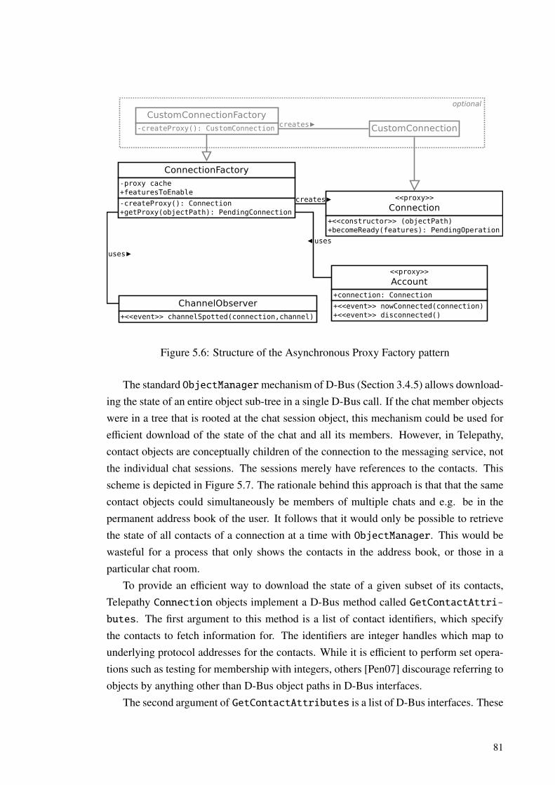
ConnectionFactory-proxy cache+featuresToEnable
-createProxy(): Connection+getProxy(objectPath): PendingConnection
<<proxy>>
Connection+<<constructor>> (objectPath)+becomeReady(features): PendingOperation
CustomConnection
CustomConnectionFactory-createProxy(): CustomConnection
<<proxy>>
Account+connection: Connection
+<<event>> nowConnected(connection)+<<event>> disconnected()
ChannelObserver+<<event>> channelSpotted(connection,channel)
creates
uses
uses
creates
optional
Figure 5.6: Structure of the Asynchronous Proxy Factory pattern
The standard ObjectManagermechanism of D-Bus (Section 3.4.5) allows download-ing the state of an entire object sub-tree in a single D-Bus call. If the chat member objectswere in a tree that is rooted at the chat session object, this mechanism could be used forefficient download of the state of the chat and all its members. However, in Telepathy,contact objects are conceptually children of the connection to the messaging service, notthe individual chat sessions. The sessions merely have references to the contacts. Thisscheme is depicted in Figure 5.7. The rationale behind this approach is that that the samecontact objects could simultaneously be members of multiple chats and e.g. be in thepermanent address book of the user. It follows that it would only be possible to retrievethe state of all contacts of a connection at a time with ObjectManager. This would bewasteful for a process that only shows the contacts in the address book, or those in aparticular chat room.
To provide an efficient way to download the state of a given subset of its contacts,Telepathy Connection objects implement a D-Bus method called GetContactAttri-butes. The first argument to this method is a list of contact identifiers, which specifythe contacts to fetch information for. The identifiers are integer handles which map tounderlying protocol addresses for the contacts. While it is efficient to perform set opera-tions such as testing for membership with integers, others [Pen07] discourage referring toobjects by anything other than D-Bus object paths in D-Bus interfaces.
The second argument of GetContactAttributes is a list of D-Bus interfaces. These
81
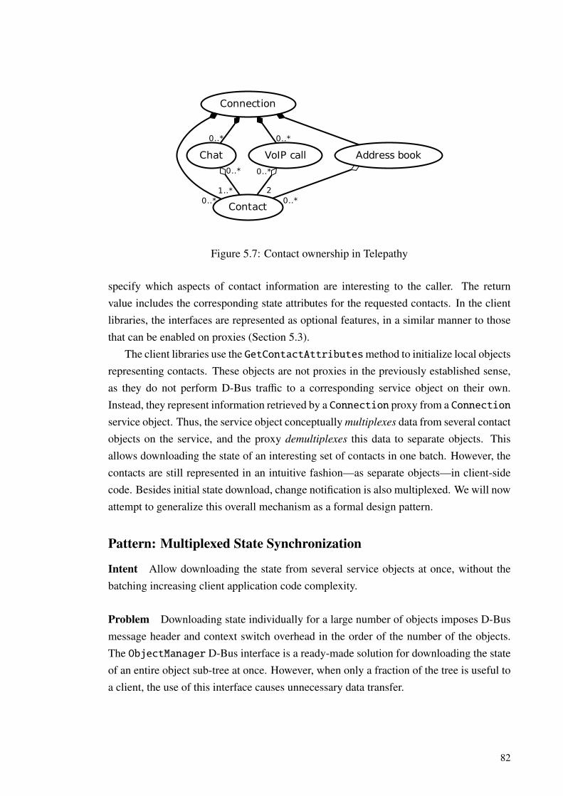
Connection
Contact0..*
Chat
0..*
VoIP call
0..*
Address book
1..*
0..*
2
0..*
0..*
Figure 5.7: Contact ownership in Telepathy
specify which aspects of contact information are interesting to the caller. The returnvalue includes the corresponding state attributes for the requested contacts. In the clientlibraries, the interfaces are represented as optional features, in a similar manner to thosethat can be enabled on proxies (Section 5.3).
The client libraries use the GetContactAttributesmethod to initialize local objectsrepresenting contacts. These objects are not proxies in the previously established sense,as they do not perform D-Bus traffic to a corresponding service object on their own.Instead, they represent information retrieved by a Connection proxy from a Connectionservice object. Thus, the service object conceptually multiplexes data from several contactobjects on the service, and the proxy demultiplexes this data to separate objects. Thisallows downloading the state of an interesting set of contacts in one batch. However, thecontacts are still represented in an intuitive fashion—as separate objects—in client-sidecode. Besides initial state download, change notification is also multiplexed. We will nowattempt to generalize this overall mechanism as a formal design pattern.
Pattern: Multiplexed State Synchronization
Intent Allow downloading the state from several service objects at once, without thebatching increasing client application code complexity.
Problem Downloading state individually for a large number of objects imposes D-Busmessage header and context switch overhead in the order of the number of the objects.The ObjectManager D-Bus interface is a ready-made solution for downloading the stateof an entire object sub-tree at once. However, when only a fraction of the tree is useful toa client, the use of this interface causes unnecessary data transfer.
82
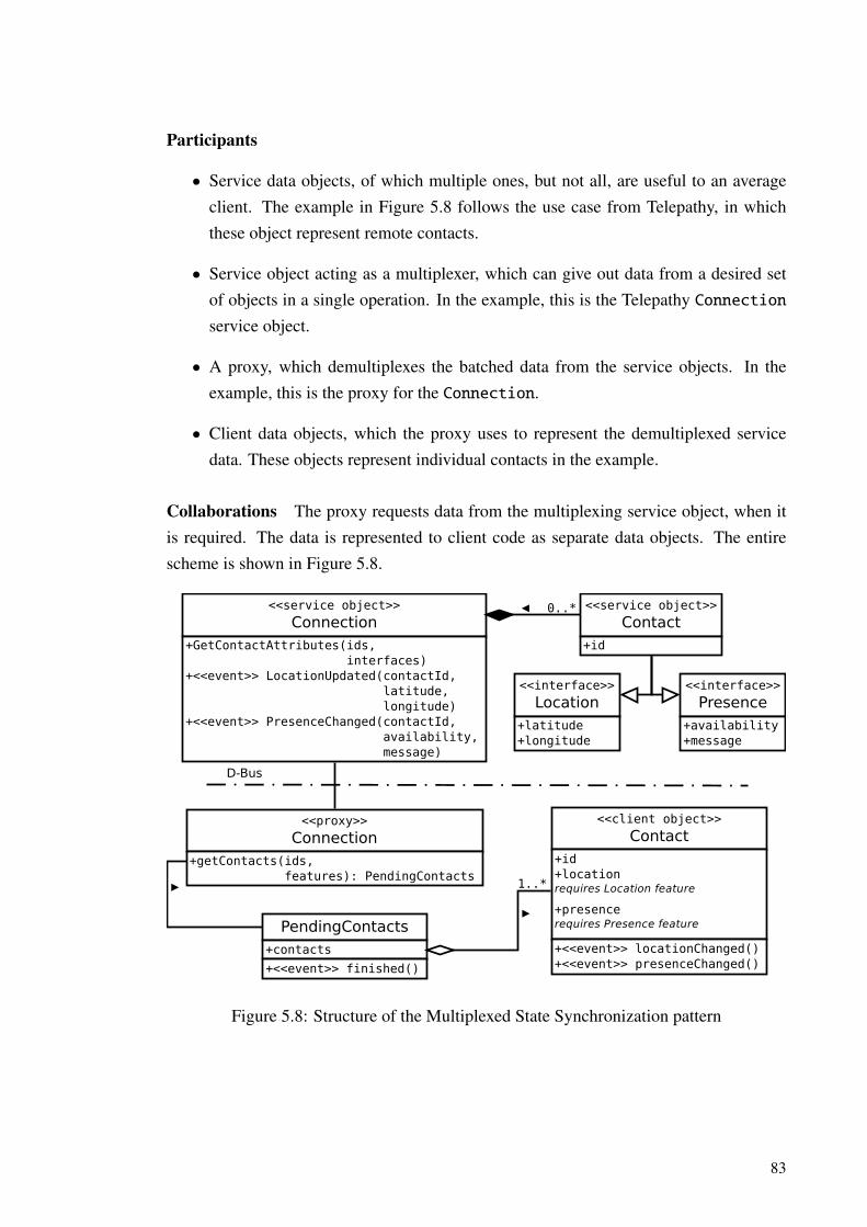
Participants
• Service data objects, of which multiple ones, but not all, are useful to an averageclient. The example in Figure 5.8 follows the use case from Telepathy, in whichthese object represent remote contacts.
• Service object acting as a multiplexer, which can give out data from a desired setof objects in a single operation. In the example, this is the Telepathy Connectionservice object.
• A proxy, which demultiplexes the batched data from the service objects. In theexample, this is the proxy for the Connection.
• Client data objects, which the proxy uses to represent the demultiplexed servicedata. These objects represent individual contacts in the example.
Collaborations The proxy requests data from the multiplexing service object, when itis required. The data is represented to client code as separate data objects. The entirescheme is shown in Figure 5.8.
<<service object>>
Connection+GetContactAttributes(ids, interfaces)+<<event>> LocationUpdated(contactId, latitude, longitude)+<<event>> PresenceChanged(contactId, availability, message)
<<service object>>
Contact+id
<<interface>>
Presence+availability+message
<<interface>>
Location+latitude+longitude
0..*
<<proxy>>
Connection+getContacts(ids, features): PendingContacts
PendingContacts+contacts
+<<event>> finished()
<<client object>>
Contact+id+locationrequires Location feature
+presencerequires Presence feature
+<<event>> locationChanged()+<<event>> presenceChanged()
1..*
D-Bus
Figure 5.8: Structure of the Multiplexed State Synchronization pattern
83

Consequences The state of an arbitrary number of objects can be downloaded witha constant number of D-Bus method calls. Objects outside the interesting set do notincrease the amount of downloaded data. However, as the proxy demultiplexes the datato independent objects, client code can still manipulate each object without regard to thebatch in which they were actually downloaded in. As such, no complexity is added to theprogramming interface that is visible to client code.
84
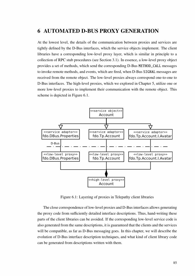
6 AUTOMATED D-BUS PROXY GENERATION
At the lowest level, the details of the communication between proxies and services aretightly defined by the D-Bus interfaces, which the service objects implement. The clientlibraries have a corresponding low-level proxy layer, which is similar in principle to acollection of RPC stub procedures (see Section 3.1). In essence, a low-level proxy objectprovides a set of methods, which send the corresponding D-Bus METHOD_CALL messagesto invoke remote methods, and events, which are fired, when D-Bus SIGNALmessages arereceived from the remote object. The low-level proxies always correspond one-to-one toD-Bus interfaces. The high-level proxies, which we explored in Chapter 5, utilize one ormore low-level proxies to implement their communication with the remote object. Thisscheme is depicted in Figure 6.1.
<<high-level proxy>>
Account
<<low-level proxy>>
fdo.Tp.Account<<low-level proxy>>
fdo.Tp.Account.I.Avatar<<low-level proxy>>
fdo.DBus.Properties
<<service adaptor>>
fdo.DBus.Properties<<service adaptor>>
fdo.Tp.Account<<service adaptor>>
fdo.Tp.Account.I.Avatar
<<service object>>
Account
D-Bus
Figure 6.1: Layering of proxies in Telepathy client libraries
The close correspondence of low-level proxies and D-Bus interfaces allows generatingthe proxy code from sufficiently detailed interface descriptions. Thus, hand-writing theseparts of the client libraries can be avoided. If the corresponding low-level service code isalso generated from the same descriptions, it is guaranteed that the clients and the serviceswill be compatible, as far as D-Bus messaging goes. In this chapter, we will describe theevolution of D-Bus interface description techniques, and what kind of client library codecan be generated from descriptions written with them.
85

6.1 Procedural Interface Description
The Introspectable standard interface of D-Bus contains one method, Introspect,which returns an XML description of the object it has been called on. This descriptionlists the methods, signals and properties in each interface that the object implements. TheD-Bus type signatures of properties and the arguments of methods and signals are alsoincluded [PCL+12]. As an example, here is a description of the standard Propertiesinterface (Section 3.4.4) in this format:
<interface name="org.freedesktop.DBus.Properties">
<method name="Get">
<arg name="Interface" type="s" direction="in" />
<arg name="Property" type="s" direction="in" />
<arg name="Value" type="v" direction="out" />
</method>
<method name="Set">
<arg name="Interface" type="s" direction="in" />
<arg name="Property" type="s" direction="in" />
<arg name="New_Value" type="v" direction="in" />
</method>
<method name="GetAll">
<arg name="Interface" type="s" direction="in" />
<arg name="Properties" type="a{sv}" direction="out" />
</method>
<signal name="PropertiesChanged">
<arg name="Interface" type="s" />
<arg name="Changed" type="a{sv}" />
<arg name="Invalidated" type="as" />
</signal>
</interface>
The D-Bus specification suggests that this format could also be used as an interface
description language (IDL), from which code can be generated [PCL+12]. The introspec-tion information is sufficient to describe what kind of messages can be sent to an object,and what it sends out, as far as the D-Bus type system is concerned. Additionally, thenames of interface members and arguments can be used as identifiers in proxy code, aslong as some adjustment is performed to make them consistent with coding conventionsin the target language. This can be sufficient for generating a useful proxy interface forvery simple interfaces. For example, the Set D-Bus method could become the followingC++-like proxy method declaration:
86
PendingOperation ∗set(const String &interface,
const String &property,
const DBusVariant &newValue);
For this simple method, this is a satisfactory interface. This is mostly due to its self-evident semantics, and the primitive types of the arguments. Let us consider a more com-plex example. The ContactsChanged signal of the ContactList interface is emittedon Telepathy Connection objects, when the contents of the user’s server-stored addressbook changes. The signal is defined as
ContactsChanged(a{u(uus)}: Changes,au: Removals) [signal]
Representing the ContactsChanged signal in a C++ proxy is no longer straight-forward. The first argument has a complex nested type—which C++ type should it bemapped to? And how should code which receives this signal interpret the integers andstrings that make up that type? They do not even have names to explain themselves, afterall. In the next section, we will describe a set of extensions to the D-Bus introspectionformat, which make it possible to solve these kinds of issues.
6.2 The Telepathy Interface Description Format
The D-Bus interfaces that Telepathy components implement are described with an ex-tended version of the D-Bus introspection format [MMHT11]. These extensions make itpossible to specify interface semantics in a more detailed fashion. The enhanced possi-bilities for code generation have led to others adopting [AFF+09] the use of this extendedformat as well.
6.2.1 Integer and string constants
The D-Bus type signature of the first argument of the ContactsChanged signal wasa{u(uus)}. This means that it is a mapping from unsigned integers to structures, whichconsist of two unsigned integers and a string. The keys of the mapping are integer iden-tifiers for contacts, and the value structure describes the disposition of the correspondingcontact in the address book. The disposition tells if the remote contact has allowed us tosee details such as whether they are online or away and so on, and if we have done thesame for them. The structure of the entire data type is shown graphically in Figure 6.2.
As illustrated in the figure, the integers in the disposition structure are actually usedto represent an enumerated type. Variables with an enumerated type can take one of just
87

Key
u Contact identifier
Value
u
u
s
Subscribe
Publish
Publish_Request
maps to
Enum: Subscription_State
0
1
2
3
4
Unknown
No
RemovedRemotely
Ask
Yes
any of
any of
Figure 6.2: Layout of the first argument of the ContactsChanged signal
a few values, each of which has a distinct meaning. The Telepathy interface descrip-tion format allows specifying the allowed values for enumerated types with the tp:enumelement, as follows:
<tp:enum name="Subscription_State" type="u">
<tp:enumvalue suffix="Unknown" value="0" />
<tp:enumvalue suffix="No" value="1" />
<tp:enumvalue suffix="Removed_Remotely" value="2" />
<tp:enumvalue suffix="Ask" value="3" />
<tp:enumvalue suffix="Yes" value="4" />
</tp:enum>
The code generator in the build system of the Telepathy-Qt library would turn this to thefollowing C++ enumerated type declaration:
enum SubscriptionState {
SubscriptionStateUnknown = 0,
SubscriptionStateNo = 1,
SubscriptionStateRemovedRemotely = 2,
SubscriptionStateAsk = 3,
SubscriptionStateYes = 4
};
A similar element, tp:flags, can be used to specify flag values for bit fields. In bit fields,a set of one-bit flag values are bitwise-OR’d together to produce a combination of flagsrepresented as an integer.
D-Bus errors have names that resemble D-Bus interface names, e.g. org.freedesk-top.DBus.Error.UnknownMethod. When a method produces an error, the error nameis given as a string in the ERROR message. The tp:possible-errors element can beattached to a D-Bus method declaration to list the errors that can result from invoking thatmethod, and to describe what meaning they have in that context. When standard D-Buserrors are not sufficient, the global tp:errors element can be used to define additionalwell-known error names, like:
88

<tp:errors namespace="org.freedesktop.Telepathy.Error">
<tp:error name="Network Error" />
<tp:error name="Not Implemented" />
</tp:errors>
The information in tp:errors elements can be used to define string constants for errornames. The client libraries also include generated string constants for D-Bus interfacenames, as these have been found useful.
6.2.2 Complex types
The tp:struct element can be used to give a name and semantics to D-Bus structures.The definition of the contact disposition structure for the ContactsChanged signal fol-lows:
<tp:struct name="Contact_Subscriptions">
<tp:member name="Subscribe" type="u" tp:type="Subscription_State" />
<tp:member name="Publish" type="u" tp:type="Subscription_State" />
<tp:member name="Publish_Request" type="s" />
</tp:struct>
In this definition, the tp:type attribute is used to link the first two structure membersto the enumerated type that was presented earlier. This attribute can also be used toreference a defined structure by its name. With this, we can define the full mapping typeof the ContactsChanged signal’s first argument, using the tp:mapping element:
<tp:mapping name="Contact_Subscription_Map">
<tp:member name="Contact_Handle" type="u" />
<tp:member name="States" type="(uus)" tp:type="Contact_Subscriptions" />
</tp:mapping>
With these type definitions, a C++ code generator could produce something like the fol-lowing code to declare the corresponding C++ types:
struct ContactSubscriptions {
SubscriptionState subscribe;
SubscriptionState publish;
String publishRequest;
};
typedef Map<unsigned int, ContactSubscriptions> ContactSubscriptionMap;
The tp:type attribute is also used to specify the semantical type to use for methodand signal arguments and properties. The characters “[]” can be appended to any type
89

name in a tp:type value to specify an array of the type to be used. For example, theTelepathy ConnectionManager interface defines a structure, which represents an al-lowed connection parameter, as follows:
<tp:struct name="Param_Spec">
<tp:member name="Name" type="s" />
<tp:member name="Flags" type="u" tp:type="Conn_Mgr_Param_Flags" />
<tp:member name="Signature" type="s" />
<tp:member name="Default_Value" type="v" />
</tp:struct>
This definition is used to declare the D-Bus property
Parameters: a(susv) [read-only property]
on the Protocol interface, with the following XML code:
<property name="Parameters"
type="a(susv)"
access="read"
tp:type="Param_Spec[]"
tp:immutable="yes" />
The tp:immutable attribute shown in the above declaration can be used to mark a prop-erty as immutable, as defined in Section 5.2.
6.2.3 Miscellaneous features
Naming types and constant values based on their semantics makes D-Bus interfaces agreat deal more self-documenting than if just the D-Bus type signatures were used. How-ever, more elaborate free-form documentation is typically desirable. The tp:docstringelement can be used to attach arbitrary textual documentation to almost any element ina D-Bus interface description, from a top-level interface to a single enumeration value.The documentation may also include XHTML markup, which can make longer runs ofdocumentation more readable. While the Telepathy interfaces are thoroughly documentedin this fashion, the tp:docstring elements were deliberately left out from the precedinginterface description fragments to make them more concise.
The tp:copyright element can be used to specify the copyright ownership for asection of an interface description. Licensing terms can be written inside tp:licenseelements. The content of both of these elements is free text.
These additions make it possible to generate, besides library code, annotated doc-umentation of D-Bus interfaces. The Telepathy D-Bus Interface Specification docu-ment [dTdCDG+12] is generated in this fashion from the interface description XML, with
90

no other input data. The specification document is the canonical source of information onhow components of the framework must communicate and behave.
91
7 CONCLUSION
In this thesis, we have analyzed the properties of the D-Bus system within the contextof established research on object-oriented software design and inter-process communica-tion. Practical considerations for the design and implementation of D-Bus-based object-oriented software have also been presented, based on these properties.
D-Bus was found to be a rather multi-faceted system. It supports both explicit invo-cation through method calls and implicit invocation via signals, and the match rules area fairly complex example of a content-based publish/subscribe subscription system. Thishas made establishing a base of comparison for our analysis fairly challenging, as researchon existing systems with each of these invocation patterns needed to be referenced. Onthe other hand, this multitude of features in D-Bus makes it possible to build elaboratemechanisms, such as our sophisticated state-caching proxy pattern (Chapter 5).
In Section 3.5, constraints for D-Bus messaging design were presented. The pseudo-blocking patterns for placing method calls were reasoned to be harmful for interactivity.Additionally, the classic pseudo-blocking pattern causes a loss of message ordering se-mantics and is prone to deadlocks, while the re-entrant variant makes class invariantsunreliable. Fully asynchronous method calls do not have these drawbacks, but are pro-grammatically unwieldy. Besides D-Bus, these conclusions would seem to apply to anyIPC system with a call packet → reply packet style of procedure invocation (see Sec-tion 3.1).
Our presentation of the software design patterns in Chapter 5 has been mainly concep-tual. Additionally, their possible effect on software complexity, performance and othernon-functional qualities has been briefly reasoned about. These patterns used togetherwould seem to reduce the complexity of inspecting and presenting the state of remoteobjects to the level of local objects, without violating the messaging constraints that wereestablished earlier, or decreasing performance substantially. However, a case study oftaking the patterns into use in an existing software system could provide empirical furtherproof for these claims. In any such effort, accuracy of performance and power consump-tion measurements will be affected by implementation details. For example, there arerecent plans [Cre10] to reassign some message routing responsibilities from the D-Busbus daemon to the operating system kernel. This alters the context switch requirements(Section 3.5.3) of D-Bus message transfer.
The design patterns presented in Chapter 5 and the interface description languagedescribed in Section 6.2 have materialized as a by-product of functional developmentof the Telepathy IM/VoIP framework. A study of adapting them in some other systemcould also provide insights on the breadth of their applicability. The multiplexed state
92
synchronization mechanism from Section 5.5 likely needs the most adjusting work to fitinto further uses besides communicating remote contact information in Telepathy.
As mentioned in Section 5.2, a basic property caching facility already exists in ageneric form in the GDBus library. This facility could perhaps be augmented with sup-port for custom change notification mechanisms and initialization of the state copy fromknown values, as present in the Telepathy client libraries. This would lower the barrierof employing these mechanisms in other software, but would likely require annotatingtheir D-Bus interface descriptions with extra information, such as how properties can bemarked as immutable in the Telepathy specification (Section 6.2.2).
We haven’t often found the necessary delay between a service object state change andthe corresponding proxy state cache update problematic. However, it requires some careto be taken in D-Bus interface design to avoid race conditions. Analyzing the consistencyproperties of the state caching pattern and its implications on interface design would bean interesting topic for future research.
In general, the Telepathy specification format (Section 6.2) has been found to be asizable improvement over basic D-Bus introspection data for code and documentationgeneration purposes. It helps avoid hand-writing lower-level parts of D-Bus softwareand thus lowers implementation effort. However, this might be dependent on the targetprogramming language; the suitability for generating code for other kinds of languagesthan the imperative C, C++ and Python remains to be seen.
A distributed software architecture built around an IPC system like D-Bus can havemany benefits over a monolithic solution. However, as illustrated by this thesis, employ-ing an IPC system optimally is far from trivial. Thus, the success of any such system isstrongly dependent on its set of accompanying reusable implementation support libraries,code generation machinery and other tools which can aid and guide in this process.
93
References
[AAB+12] Sunil Mohan Adapa, Emanuele Aina, Ross Burton, Xavier Claessens,Alban Crequy, Guillaume Desmottes, Dafydd Harries, Philippe Kalaf,Alberto Mardegan, Robert McQueen, Simon McVittie, Mads Chr.Olesen, Pekka Pessi, Senko Rasic, Ole André Ravnaas, Olli Salli,Sjoerd Simons, Rob Taylor, Will Thompson, and Mikhail Zabaluev.telepathy-glib api reference. http://telepathy.freedesktop.org/doc/telepathy-glib/, 2012. Accessed April 26, 2012.
[AFF+09] Karl-Erik Ärzén, Pascal Faure, Gerhard Fohler, Marco Mattavelli,Alexander Neundorf, and Vanessa Romero. Interface speci-fication. http://www.actors-project.eu/wiki/images/a/a2/
D1f-2009-01-31.pdf, 2009. Accessed May 17, 2012.
[ATK92] A. L. Ananda, B. H. Tay, and E. K. Koh. A survey of asynchronous remoteprocedure calls. SIGOPS Oper. Syst. Rev., 26:92–109, April 1992.
[BA04] M.A.S. Boxall and S. Araban. Interface metrics for reusability analysisof components. In Software Engineering Conference, 2004. Proceedings.
2004 Australian, pages 40 – 51, 2004.
[BALL90] Brian N. Bershad, Thomas E. Anderson, Edward D. Lazowska, andHenry M. Levy. Lightweight remote procedure call. ACM Trans. Comput.
Syst., 8:37–55, February 1990.
[BBG+63] J.W. Backus, F.L. Bauer, J. Green, C. Katz, J. McCarthy, P. Naur, A.J.Perlis, H. Rutishauser, K. Samelson, B. Vauquois, et al. Revised reporton the algorithmic language algol 60. The Computer Journal, 5(4):349–367, 1963.
[BC90] Gilad Bracha and William Cook. Mixin-based inheritance. In Pro-
ceedings of the European conference on object-oriented programming
on Object-oriented programming systems, languages, and applications,
94
OOPSLA/ECOOP ’90, pages 303–311, New York, NY, USA, 1990.ACM.
[BCL+87] B.N. Bershad, D.T. Ching, E.D. Lazowska, J. Sanislo, and M. Schwartz.A remote procedure call facility for interconnecting heterogeneous com-puter systems. Software Engineering, IEEE Transactions on, SE-13(8):880 – 894, aug. 1987.
[Ber00] Joseph Bergin. Multiple inheritance in java. http://csis.pace.edu/~bergin, June 2000. Accessed January 19, 2012.
[BN84] Andrew D. Birrell and Bruce Jay Nelson. Implementing remote procedurecalls. ACM Trans. Comput. Syst., 2:39–59, February 1984.
[CCHO89] P. S. Canning, W. R. Cook, W. L. Hill, and W. G. Olthoff. Interfaces forstrongly-typed object-oriented programming. In Conference proceedings
on Object-oriented programming systems, languages and applications,OOPSLA ’89, pages 457–467, New York, NY, USA, 1989. ACM.
[CHC90] William R. Cook, Walter Hill, and Peter S. Canning. Inheritance is notsubtyping. In Proceedings of the 17th ACM SIGPLAN-SIGACT sympo-
sium on Principles of programming languages, POPL ’90, pages 125–135, New York, NY, USA, 1990. ACM.
[Coh84] A. Toni Cohen. Data abstraction, data encapsulation and object-orientedprogramming. SIGPLAN Not., 19:31–35, January 1984.
[Cre08] Alban Crequy. Importance of the scheduling priority in d-bus. http://www.maemonokian900.com/maemo-news/
importance-of-the-scheduling-priority-in-d-bus/, 2008.Accessed May 17, 2012.
[Cre10] Alban Crequy. D-bus in the kernel, faster! http://alban-apinc.
blogspot.fi/2011/12/d-bus-in-kernel-faster.html, 9 2010.Accessed June 4, 2012.
[DMN67] Ole-Johan Dahl, Bjørn Myhrhaug, and Kristen Nygaard. Simula 67 com-
mon base language. Norwegian Computing Center, 1967.
[DMN68] Ole-Johan Dahl, Bjørn Myhrhaug, and Kristen Nygaard. Some featuresof the simula 67 language. In Proceedings of the second conference on
Applications of simulations, pages 29–31. Winter Simulation Conference,1968.
95
[DSC92] A. Dave, M. Sefika, and R.H. Campbell. Proxies, application interfaces,and distributed systems. In Object Orientation in Operating Systems,
1992., Proceedings of the Second International Workshop on, pages 212–220, sep 1992.
[dTdCDG+12] Daniel d’Andrada T. de Carvalho, Guillaume Desmottes, Julien Gilli,Dafydd Harries, Tobias Hunger, Andre Magalhaes, Robert McQueen, Si-mon McVittie, Mads Chr. Olesen, Senko Rasic, Ole Andre Vadla Rav-naas, Olli Salli, Sjoerd Simons, Raphael Slinckx, Rob Taylor, NaveenVerma, and Mikhail Zabaluev. Telepathy d-bus interface specification,version 0.26.0. http://telepathy.freedesktop.org/spec, 2012.Accessed June 4, 2012.
[EFGK03] Patrick Th. Eugster, Pascal A. Felber, Rachid Guerraoui, and Anne-MarieKermarrec. The many faces of publish/subscribe. ACM Comput. Surv.,35:114–131, June 2003.
[EGD01] Patrick Th. Eugster, Rachid Guerraoui, and Christian Heide Damm. Onobjects and events. In Proceedings of the 16th ACM SIGPLAN conference
on Object-oriented programming, systems, languages, and applications,OOPSLA ’01, pages 254–269, New York, NY, USA, 2001. ACM.
[GG04] Nasib S. Gill and P. S. Grover. Few important considerations for deriv-ing interface complexity metric for component-based systems. SIGSOFT
Softw. Eng. Notes, 29(2):4–4, March 2004.
[GHJV95] E. Gamma, R. Helm, R. Johnson, and J. Vlissides. Design Patterns: ele-
ments of reusable object-oriented software. Addison-Wesley, 1995.
[GN91] D. Garlan and D. Notkin. Formalizing design spaces: Implicit invocationmechanisms. In VDM’91 Formal Software Development Methods, pages31–44. Springer, 1991.
[Goo75] John B. Goodenough. Structured exception handling. In Proceedings of
the 2nd ACM SIGACT-SIGPLAN symposium on Principles of program-
ming languages, POPL ’75, pages 204–224, New York, NY, USA, 1975.ACM.
[GS93] David Garlan and Curtis Scott. Adding implicit invocation to traditionalprogramming languages. In Proceedings of the 15th international confer-
ence on Software Engineering, ICSE ’93, pages 447–455, Los Alamitos,CA, USA, 1993. IEEE Computer Society Press.
96

[Har08] Dafydd Harries. Telepathy rationale. http://telepathy.
freedesktop.org/wiki/Rationale, 2008. Project wiki page. Ac-cessed May 18, 2012.
[HD93] Y.-M. Huang and Y.-S. Duan. The design and implementation of a dis-tributed object-oriented knowledge-based system for hierarchical simula-tion modeling. In Proceedings of the 4th Annual Conference on AI, Simu-
lation and Planning in High Autonomy Systems, pages 164–170, Tucson,AZ, USA, 1993.
[HOD+11] Dafydd Harries, Mads Chr. Olesen, Guillaume Desmottes, Alban Cre-quy, Danielle Madeley, and Will Thompson. Telepathy developer notes:Tubes. http://telepathy.freedesktop.org/wiki/Tubes, 2011.Project wiki page. Accessed November 13, 2011.
[Hor90] Chris Horn. Is object orientation a good thing for distributed systems? InWolfgang Schröder-Preikschat and Wolfgang Zimmer, editors, Progress
in Distributed Operating Systems and Distributed Systems Management,volume 433 of Lecture Notes in Computer Science, pages 60–74. SpringerBerlin / Heidelberg, 1990.
[Hug02] Elliott Hughes. How many trivial getter methods does java have? SIG-
PLAN Not., 37:19–24, August 2002.
[JTM08] Matthew Johnson, Alp Toker, and Thiago Macieira. D-busbinding errors. http://www.freedesktop.org/wiki/Software/
DBusBindingErrors, 2008. Accessed February 8, 2012.
[Lie86] Henry Lieberman. Using prototypical objects to implement shared be-havior in object-oriented systems. In Conference proceedings on Object-
oriented programming systems, languages and applications, OOPLSA’86, pages 214–223, New York, NY, USA, 1986. ACM.
[Lin10] Linux man-pages project. UNIX(7) - unix, AF_UNIX, AF_LOCAL: Sock-
ets for local interprocess communication, 2010.
[Lov05] Robert Love. Get on the d-bus. Linux Journal, 130, 2005. Also availableas http://www.linuxjournal.com/article/7744.
[LS88] B. Liskov and L. Shrira. Promises: linguistic support for efficient asyn-chronous procedure calls in distributed systems. In Proceedings of the
97

ACM SIGPLAN 1988 conference on Programming Language design and
Implementation, PLDI ’88, pages 260–267, New York, NY, USA, 1988.ACM.
[LZ74] Barbara Liskov and Stephen Zilles. Programming with abstract datatypes. In Proceedings of the ACM SIGPLAN symposium on Very high
level languages, pages 50–59, New York, NY, USA, 1974. ACM.
[Mad11] Danielle Madeley. Telepathy. In The Architecture of Open Source Ap-
plications. Lulu.com, 2011. Also available as http://www.aosabook.org/en/telepathy.html.
[Mar96] R.C. Martin. The interface segregation principle: One of the many prin-ciples of ood. The C++ Report, 8:30–36, 1996.
[McV08] Simon McVittie. Why you shouldn’t block on d-bus calls. Technical blogpost. smcv.pseudorandom.co.uk/2008/11/nonblocking/, 11 2008.
[Mey92] B. Meyer. Applying ‘design by contract’. Computer, 25(10):40 –51, oct1992.
[MMHT11] Robert McQueen, Simon McVittie, Dafydd Harries, and Will Thomp-son. Telepathy developer notes: Dbusspec. http://telepathy.
freedesktop.org/wiki/DbusSpec, 2011. Project wiki page. Ac-cessed May 11, 2012.
[NGGS93] D. Notkin, D. Garlan, W. Griswold, and K. Sullivan. Adding implicitinvocation to languages: Three approaches. Object Technologies for Ad-
vanced Software, pages 489–510, 1993.
[OPSS93] Brian Oki, Manfred Pfluegl, Alex Siegel, and Dale Skeen. The informa-tion bus: an architecture for extensible distributed systems. In Proceed-
ings of the fourteenth ACM symposium on Operating systems principles,SOSP ’93, pages 58–68, New York, NY, USA, 1993. ACM.
[PCL+12] Havoc Pennington, Anders Carlsson, Alexander Larsson, Sven Herzberg,Simon McVittie, and David Zeuthen. D-bus specification, version0.19. http://dbus.freedesktop.org/doc/dbus-specification.html, 2012. Accessed May 10, 2012.
[Pen07] Havoc Pennington. Best d-bus practices. http://blog.ometer.com/2007/05/17/best-d-bus-practices/, 5 2007. Technical blog post.Accessed May 16, 2012.
98

[Pen08] Havoc Pennington. Synchronous io never ok. http://blog.ometer.com/2008/09/07/synchronous-io-never-ok/, 9 2008. Technicalblog post. Accessed February 9, 2012.
[Pet07] R.P.A. Petrick. Planning for desktop services. In Proceed-
ings of the 2007 International Conference on Automated Plan-
ning and Scheduling, Providence, Rhode Island, USA, sep 2007.ICAPS. Available at http://abotea.rsise.anu.edu.au/
satellite-events-icaps07/workshop7/paper9.pdf.
[RSW98] J.-P. Redlich, M. Suzuki, and S. Weinstein. Distributed object technologyfor networking. Communications Magazine, IEEE, 36(10):100 –111, oct1998.
[S+00] D. Sweet et al. DCOP—desktop communication protocol. In KDE 2.0
Development, chapter 13. Sams, 2000.
[SB94] R. Scheifler and J. Brown. Inter-client exchange (ice) protocol, 1994.
[Sha86] Marc Shapiro. Structure and Encapsulation in Distributed Systems: theProxy Principle. In Proceedings of the 6th International Conference on
Distributed Computing Systems, pages 198–204, Cambridge, MA, USA,États-Unis, 1986. IEEE.
[SMM12] Olli Salli, Andre Magalhaes, and Simon McVittie. Telepathy-qt. http://telepathy.freedesktop.org/doc/telepathy-qt/, 2012. Refer-ence documentation. Accessed April 24, 2012.
[Sny86] Alan Snyder. Encapsulation and inheritance in object-oriented program-ming languages. In Conference proceedings on Object-oriented program-
ming systems, languages and applications, OOPLSA ’86, pages 38–45,New York, NY, USA, 1986. ACM.
[Tho11] Will Thompson. The slothful ways of d-bus. http://willthompson.co.uk/talks/the-slothful-ways-of-d-bus.pdf, 2011. DesktopSummit 2011 talk. Accessed April 27, 2012.
[Web01] Adam Brooks Webber. What is a class invariant? In Proceedings of
the 2001 ACM SIGPLAN-SIGSOFT workshop on Program analysis for
software tools and engineering, PASTE ’01, pages 86–89, New York, NY,USA, 2001. ACM.
99

[Weg87] Peter Wegner. Dimensions of object-based language design. In Confer-
ence proceedings on Object-oriented programming systems, languages
and applications, OOPSLA ’87, pages 168–182, New York, NY, USA,1987. ACM.
[WFN90] E.F. Walker, R. Floyd, and P. Neves. Asynchronous remote operation ex-ecution in distributed systems. In Distributed Computing Systems, 1990.
Proceedings., 10th International Conference on, pages 253 –259, may-1jun 1990.
[Wit05] G. Wittenburg. Desktop ipc. http://page.mi.fu-berlin.de/
gwitten/studies/desktop_ipc.pdf, 2005. Course essay. AccessedNovember 13, 2011.
[Wol92] M. Wolczko. Encapsulation, delegation and inheritance in object-orientedlanguages. Software Engineering Journal, 7(2):95 –101, mar 1992.
[XZ02] Liang Xianzhong and Wang Zhenyu. Event-based implicit invocation de-centralized in ada. Ada Lett., XXII:11–16, March 2002.
[Zeu12] David Zeuthen. Gdbus highlevel d-bus support. http://developer.gnome.org/gio/unstable/gdbus-convenience.html, 2012. Refer-ence documentation. Accessed April 24, 2012.
100