building management installation, operation, and
TRANSCRIPT

A0023368 February 2018 Rev. 1.06
Building Management Installation, Operation, and Maintenance Manual
Save these instructions. This document is the property of the owner of this equipment and is required for future maintenance. Leave this document with the owner when installation & setup is complete.
WARNING!! Wiring of the Communication Module and associated devices may involve working inside of a UL508A electrical panel. Proper precautions should be taken to reduce potential risk of shock. Wiring should
be performed by qualified personnel only.

2

3
TABLE OF CONTENTS WARRANTY .................................................................................................................................................. 4 INSTALLATION ............................................................................................................................................. 5
Wiring ........................................................................................................................................................ 5 Field Wiring Equipment to the CASLink Communication Module ............................................................ 5 Remote Wall Mounted CORE & PCU CORE ........................................................................................... 6 PCU Advanced Filter Monitoring Module with ECPM03 .......................................................................... 6 Obtaining a Valid Internet Connection ...................................................................................................... 7
Wiring to the Local Area Network (Direct Internet Connection) ........................................................... 7 Network Requirements..................................................................................................................... 7
Confirming Internet Connection for CASLink ....................................................................................... 8 Module Activation & Registration .............................................................................................................. 9
Registration .......................................................................................................................................... 9 Initial Settings for a New Module in CASLink ......................................................................................... 12
Defining the Occupancy Schedule ..................................................................................................... 12 Module Editor (Service or Admin Access Only) ...................................................................................... 13
Defining Tags and Areas (Name and Location) ................................................................................. 14 Defining & Customizing Alert Emails & Alarms .................................................................................. 16 Adding Custom Alarms ....................................................................................................................... 16 Adding Custom Email Alert Events .................................................................................................... 18
End User Guide ...................................................................................................................................... 19 Log In .................................................................................................................................................. 19 Main Page Navigation ........................................................................................................................ 20 Monitoring ........................................................................................................................................... 21 CORE Fire Protection ......................................................................................................................... 22 Pollution Control Monitor .................................................................................................................... 23 ECPM03 Hood Control Panel (SC and DCV) .................................................................................... 24 Control ................................................................................................................................................ 25 RTULink .............................................................................................................................................. 25
Navigating Sensor Data .......................................................................................................................... 26 RTULink Control Board ........................................................................................................................... 28
Schedule ............................................................................................................................................. 29 Thermostat ......................................................................................................................................... 31 Settings ............................................................................................................................................... 31
MAINTENANCE .......................................................................................................................................... 32 Module Registration Parameter Documentation ................................................................................ 32
4
WARRANTY
This equipment is warranted to be free from defects in materials and workmanship, under normal use and service, for a period of 24 months from date of shipment. This warranty shall not apply if:
1. The equipment is not installed by a qualified installer per the MANUFACTURER’S installation instructions shipped with the product.
2. The equipment is not installed in accordance with federal, state and local codes and regulations.
3. The equipment is misused or neglected.
4. The equipment is not operated within its published capacity.
5. The invoice is not paid within the terms of the sales agreement.
The MANUFACTURER shall not be liable for incidental and consequential losses and damages potentially attributable to malfunctioning equipment. Should any part of the equipment prove to be defective in material or workmanship within the 24 month warranty period, upon examination by the MANUFACTURER, such part will be repaired or replaced by MANUFACTURER at no charge. The BUYER shall pay all labor costs incurred in connection with such repair or replacement. Equipment shall not be returned without MANUFACTURER’S prior authorization and all returned equipment shall be shipped by the BUYER, freight prepaid to a destination determined by the MANUFACTURER.
5
INSTALLATION
It is imperative that this unit is installed and operated with the designed electrical supply in accordance with this manual. If there are any questions about any items, please call the service department at 1-866-784-6900 for warranty and technical support issues.
Wiring WARNING: Wiring should be performed by qualified personnel only. Most wiring related to the CASLink Building Management System is low voltage signal wiring, however it is typically installed near high voltage wiring posing risk of shock. Proper precautions must be taken.
Field Wiring Equipment to the CASLink Communication Module
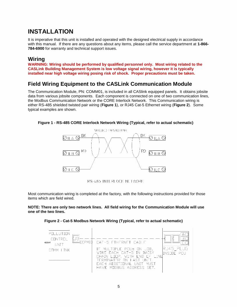
The Communication Module, PN: COMM01, is included in all CASlink equipped panels. It obtains jobsite data from various jobsite components. Each component is connected on one of two communication lines, the Modbus Communication Network or the CORE Interlock Network. This Communication wiring is either RS-485 shielded twisted pair wiring (Figure 1), or RJ45 Cat-5 Ethernet wiring (Figure 2). Some typical examples are shown.
Most communication wiring is completed at the factory, with the following instructions provided for those items which are field wired. NOTE: There are only two network lines. All field wiring for the Communication Module will use one of the two lines.
Figure 2 - Cat-5 Modbus Network Wiring (Typical, refer to actual schematic)
Figure 1 - RS-485 CORE Interlock Network Wiring (Typical, refer to actual schematic)

6
Remote Wall Mounted CORE & PCU CORE
Remote (Wall Mounted) CORE Hood & PCU CORE Fire Protection circuit boards transfer data to the Communication Module through the CORE Interlock Network only. This is typically shown as terminal blocks ILA, ILB, and ILC in each respective panel.
1. Wire ILA, ILB, and ILC of the Master CORE circuit board to ILA, ILB, and ILC of the Hood Control Panel housing the Communication Module (Figure 1)
2. If additional CORE boards are present (such as PCU CORE, 2nd Remote CORE, etc.) wire ILA, ILB, ILC of those panels to ILA, ILB, ILC of the Master CORE panel.
NOTE that doing this forces all CORE boards in the same fire group to activate simultaneously if any panel activates due to a fire. You may use DIP switch 6 and 7 on the CORE board to edit fire groups. Refer to the CORE Operation & Installation Manual.
3. Confirm DIP Switch Settings on all CORE circuit boards vs. the current CORE Operation & Installation Manual. See Table 1 for typical arrangements of 1 or 2 CORE panels.
NOTE: Improper DIP Switch settings will result in failed communication with the Communication Module. Power must be cycled to the CORE circuit board for new dip switch settings to initiate.
4. For ECPM03 based Hood Control Panels with digital LCD Interface, a Cat-5 Ethernet Cable must be run from J3 of the ECPM03 board to J5 of the Master CORE board. An end of line resistor plug (PN: EOL120A) must be installed in J6 of the CORE circuit board if it is the final component in this Modbus Communication Loop.
Table 1 - Typical CORE Dip Switch Arrangement
Only One CORE Panel on the network
CORE Board # Dip 1 Dip 2 Dip 3 Dip 4 Dip 5 Dip 6 Dip 7 Dip 8
1st (Master) ON OFF OFF OFF ON OFF OFF ON
Two CORE Panels on the network
CORE Board # Dip 1 Dip 2 Dip 3 Dip 4 Dip 5 Dip 6 Dip 7 Dip 8
1st (Master) OFF ON OFF OFF ON OFF OFF ON
2nd (Slave) ON OFF OFF OFF OFF OFF OFF ON
For 3 or more panels, refer to the CORE Operation & Installation Manual.
PCU Advanced Filter Monitoring Module with ECPM03
PCU Advanced Filter Monitoring Modules (AFM) are not fire related, and therefore connect to the standard Modbus Network for communication. Each PCU AFM comes equipped, within its control panel internal to the PCU, a pair of RJ45 Cat-5 connection ports. Modbus wiring shall be run from J3 of the ECPM03 circuit board associated with the Communication Module, to either of these two RJ45 ports within the PCU AFM cabinet (Figure 2). Additional PCU AFM modules should be wired on this same daisy chain loop with an end-of-line terminator at the final location. Communication in this arrangement travels from the PCU AFM, through the ECPM03, and into the Communication Module.
7
Obtaining a Valid Internet Connection
A reliable internet connection is required for proper Communication Module data monitoring. This connection preferably comes in the form of a hard wired Cat-5 Ethernet connection directly from the building’s Local Area Network (LAN). Alternatively a wireless cellular gateway can be used to connect the module in the event that a LAN connection is unavailable (note, cellular data charges will apply).
Wiring to the Local Area Network (Direct Internet Connection)
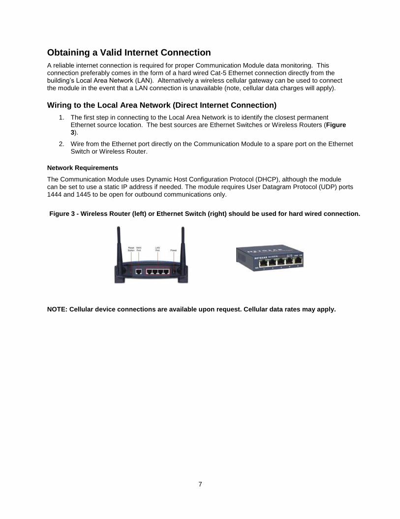
1. The first step in connecting to the Local Area Network is to identify the closest permanent Ethernet source location. The best sources are Ethernet Switches or Wireless Routers (Figure 3).
2. Wire from the Ethernet port directly on the Communication Module to a spare port on the Ethernet Switch or Wireless Router.
Network Requirements
The Communication Module uses Dynamic Host Configuration Protocol (DHCP), although the module can be set to use a static IP address if needed. The module requires User Datagram Protocol (UDP) ports 1444 and 1445 to be open for outbound communications only.
NOTE: Cellular device connections are available upon request. Cellular data rates may apply.
Figure 3 - Wireless Router (left) or Ethernet Switch (right) should be used for hard wired connection.

8
Confirming Internet Connection for CASLink The Communication Module conveniently has three LED indicators under the clear cover to help diagnose a proper internet connection. The first is the Green LED, which signifies that a proper physical Ethernet connection has been made. It does not confirm that a valid internet connection has been made. The second is the Yellow LED, which signifies activity on the Ethernet port. The rate of flashing of the Yellow LED will vary with activity level. If there is no activity, the connection to the Ethernet Switch or Wireless Bridge is suspect. The Yellow LED having activity does not confirm that a valid internet connection has been made. The third is the Red LED. The table below should be used to diagnose the flashes of the Red LED. One short flash every 3 seconds is the only method to confirm that a valid connection has been made to the CASLink servers. The Red LED takes approximately 10 seconds to begin flashing upon power-up. Note that certain configuration changes on the module may take up to 10 minutes to take effect. If a module local setting is modified, give it 10 minutes to update the red LED.
Table 2 - Flash codes for the On-Module Red LED indicator
Number of
Flashes Description Notes
1 Normal operation Normal Operation (1 short flash every 3 seconds)
2 Waiting for DHCP Check that the Switch or Bridge is communicating & properly configured.
3 Configuration mode enabled This mode is enabled via DIP switch 3. In this mode a web server is enabled for configuration changes to be made. Turn off DIP switch 3 to remove this code.
4 No CORE interlock network traffic detected Not present if CORE is not configured on the Module’s Internal Server. If present, CORE Interlock Network is miswired or CORE board dip switch settings are incorrect.
5 Communication with CAS servers not established
Typically no internet or CASLink server down.
6 Unspecified fault Normally a flash CRC error. Contact Service to order a replacement.
- Solid red light that flashes every few seconds The module is not receiving a heartbeat response from CASLink. Check network settings and make sure UDP port 1444 is open for outbound traffic.
- Rapid blinking red light The module is trying to send data but is not receiving a response from CASLink. Check network settings and make sure that UDP port 1445 is open for outbound traffic.
9
Module Activation & Registration Once a valid connection to the CASLink server has been established (one short flash on Red LED every three seconds), proceed to activate the Module through the CASLink Module Registration Wizard.
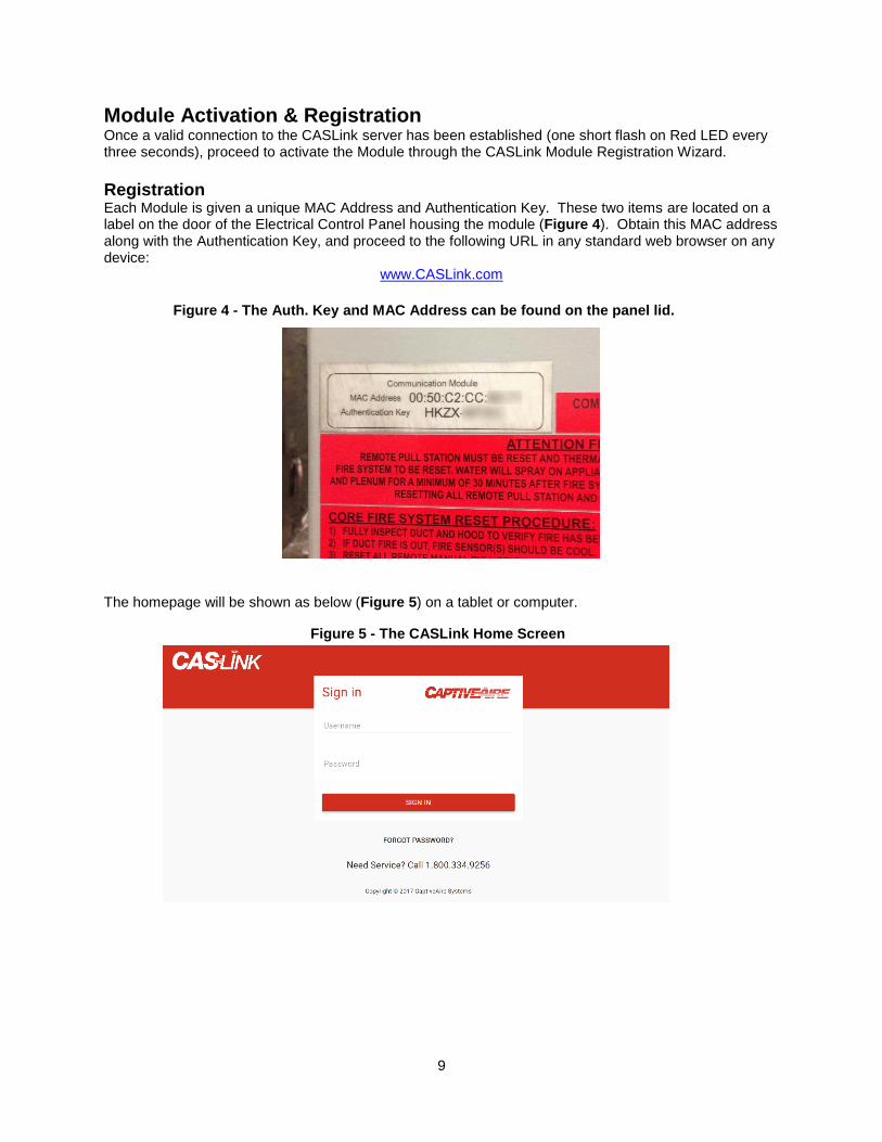
Registration Each Module is given a unique MAC Address and Authentication Key. These two items are located on a label on the door of the Electrical Control Panel housing the module (Figure 4). Obtain this MAC address along with the Authentication Key, and proceed to the following URL in any standard web browser on any device:
www.CASLink.com
The homepage will be shown as below (Figure 5) on a tablet or computer.
Figure 4 - The Auth. Key and MAC Address can be found on the panel lid.
Figure 5 - The CASLink Home Screen

10
STEP 1 Log in to the website utilizing your NOLA credentials. If you do not have NOLA credentials, please contact your local service representative for additional instructions. Select “Register New Module” (circled to the right in two places) to initiate the Module Registration Wizard.
STEP 2 Enter Authentication Information: Enter the Authentication Key & MAC Address: Obtain from label on the door of the control panel (Figure 4). Select “NEXT”.
11
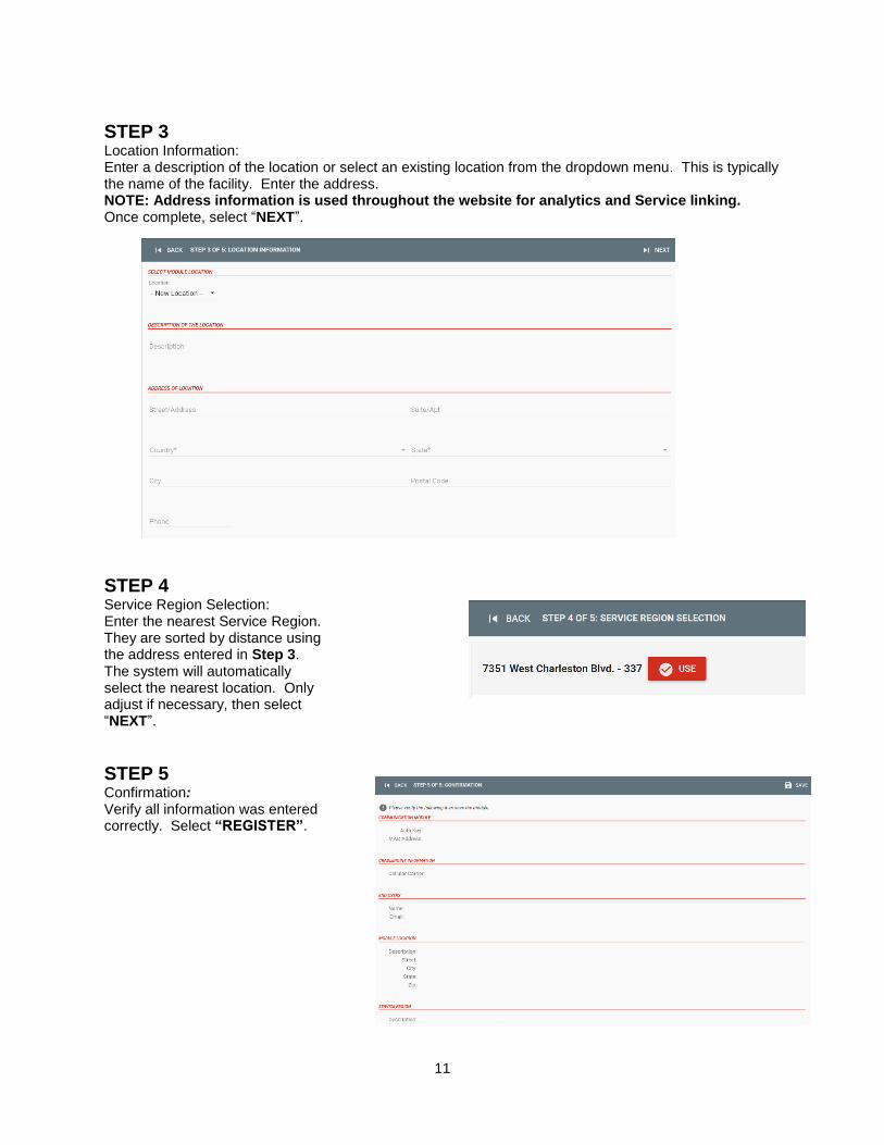
STEP 3 Location Information: Enter a description of the location or select an existing location from the dropdown menu. This is typically the name of the facility. Enter the address. NOTE: Address information is used throughout the website for analytics and Service linking. Once complete, select “NEXT”.
STEP 4
Service Region Selection: Enter the nearest Service Region. They are sorted by distance using the address entered in Step 3. The system will automatically select the nearest location. Only adjust if necessary, then select “NEXT”.
STEP 5 Confirmation: Verify all information was entered correctly. Select “REGISTER”.

12
Initial Settings for a New Module in CASLink
Defining the Occupancy Schedule
The range and activation of most email alert events depend specifically on the occupied/unoccupied state of the building. A simple example of this is the “Fan Run Status” alert. If a fan is running during the occupied period this is considered normal operation; however, if a fan is running during the unoccupied period this is considered an alert condition. As such, a properly defined Building Schedule is an extremely important item in the CASLink monitoring setup procedure. NOTE: A schedule must match the end-user’s building occupancy to prevent nuisance alert emails. By default, all Modules are preset with a 7:00 AM – 10:00 PM schedule. To modify the Occupied/Unoccupied schedule follow the steps below:
a) Enter the settings area by selecting the “SETTINGS” icon.
b) Select the “OCCUPANCY” Icon to access the Occupancy Editor (Figure 6).
c) Click or press (touchscreen) and drag over the desired occupancy ranges. a. If starting on an empty time block, all blocks will be filled when the cursor is released. b. If starting on a filled time block, all blocks will be emptied when the cursor is released. c. Each block represents 15 minutes of time.
d) Confirm that the text version of the schedule, shown below the schedule editor itself, matches what is expected.
e) Select “SAVE” to complete the Occupancy Editor.
f) Select “ROLLBACK” only if trying to revert to the previously saved schedule.
Figure 6 - The Occupancy Editor

13
Module Editor (Service or Admin Access Only)
By default, when completing the Module Registration Process, each module is given a standard pre-defined set of Alert Ranges, Sensor Names, Areas, and Email Events. All of this information should be customized to suit the specific needs of the customer. To access the module editor, login in using Employee Credentials (NOLA credentials). If you are not a CASLink employee and do not have NOLA credentials, contact your service or sales region for documentation. If the Module Registration Process was just completed, you should already be signed in. Once logged in, you may select the specific module by searching for the name, location address, or the MAC address. The Module Editor can be accessed by selecting the “Location” icon. A drop down menu will appear, select “Communication Modules” (Figure 7). After loading the module, you should now see the module’s Mac Address (00:xx:00:xx:00:xx). Most installations will only have one MAC Address listed on this page. If there is more than one module at the location, each module has to be edited individually. However, the data from the modules will be presented as one location to the end-user.
Figure 7 - Accessing the Module Editor via the Location Menu

14
Defining Tags and Areas (Name and Location)
Hardware components and sensors are not given a specific tag (name) and area (location) by default. For example, “CoreBoard 1” is the generic hardware component title for a CORE system. The area for this system is blank. An example of a properly named hardware component would be “CoreBoard Hood #1”. An example of a properly named area would be “Kitchen Area”. Tags and areas can be defined by the following procedure:
1. Select the hardware component, e.g. “CoreBoard”, from the hardware tree that needs the area defined.
2. To edit the tag and area (Figure 8), select the “Pencil” icon:
To edit tag name, select the tag box. Type in new tag name.
To add a new area, select the “+” icon. Type in new area name.
To add an existing area, select the drop down menu.
3. To save, select the “Save Disc” icon. To cancel, select the “x” icon.
Figure 8 - Editing a Complete Hardware Name and Area

15
Proper sensor naming convention should indicate the sensor type and the component it is associated with (hood #1, exhaust fan #4, etc.). Appliance type, if available, can be valuable as well. Sensor areas can be defined by their hardware area (if no specific sensor area is defined) or individually. They are not required to be in the same area as their hardware component. It is recommended to keep the number of areas to a minimum. Placing sensors in the same area allows for overlaying plots, which is critical for data analysis. An example of a properly named sensor would be “Hood #1 (Fryer) Duct Temp”. An example of a poorly named sensor would be “Duct Stat #1”. Tags and areas can be defined by the following procedure:
1. Select the sensor from the hardware tree that needs the area defined.
2. To edit the tag and area (Figure 9), select the “Pencil” icon:
To edit tag name, select the tag box. Type in new tag name.
To add a new area, select the “+” icon. Type in new area name.
To add an existing area, select the drop down menu.
3. To save, select the “Save Disc” icon. To cancel, select the “x” icon.
4. After all sensors have been appropriately named and correspond to appropriate areas, review the main screen. Confirm that the areas are defined, sensors are where expected, and unnecessary areas are not present. Keep in mind that having too many areas makes the navigation cumbersome. Simple and effective area naming is the best approach.
Figure 9 - Editing a Specific Sensor Name and Area
NOTE: Sensors can be placed in areas separate from their hardware location. For example, a temperature sensor could be mounted in a back kitchen, while the hood control panel is mounted in the front kitchen. For this reason, it is extremely important during startup to properly label the sensors so that each can be defined without on-site knowledge.
16
Defining & Customizing Alert Emails & Alarms
Alarms are what drive the email and service notification portion of CASLink BMS. By default, upon completion of the Module Registration Process, each module is given a standard pre-defined set of alarms and a pre-made email notification set. NOTE: Pre-defined alarm cannot be changed. However, the email functions can be enabled/disabled. By default, email notification is added to all sensors for warning conditions for the following users:
The engineering sales office associated with the original design.
The service region selected during module registration. Additional custom alerts or email notifications can be added to individual sensors or parameters by following the instructions below. Valid reasons for setting up additional alerts would be to:
Monitor a specific sensor for a suspect component.
Define alarm variable email activation setpoints that are more reactive than the standard setpoints.
Monitor activation time by daily email for a component or sensor to watch for trends.
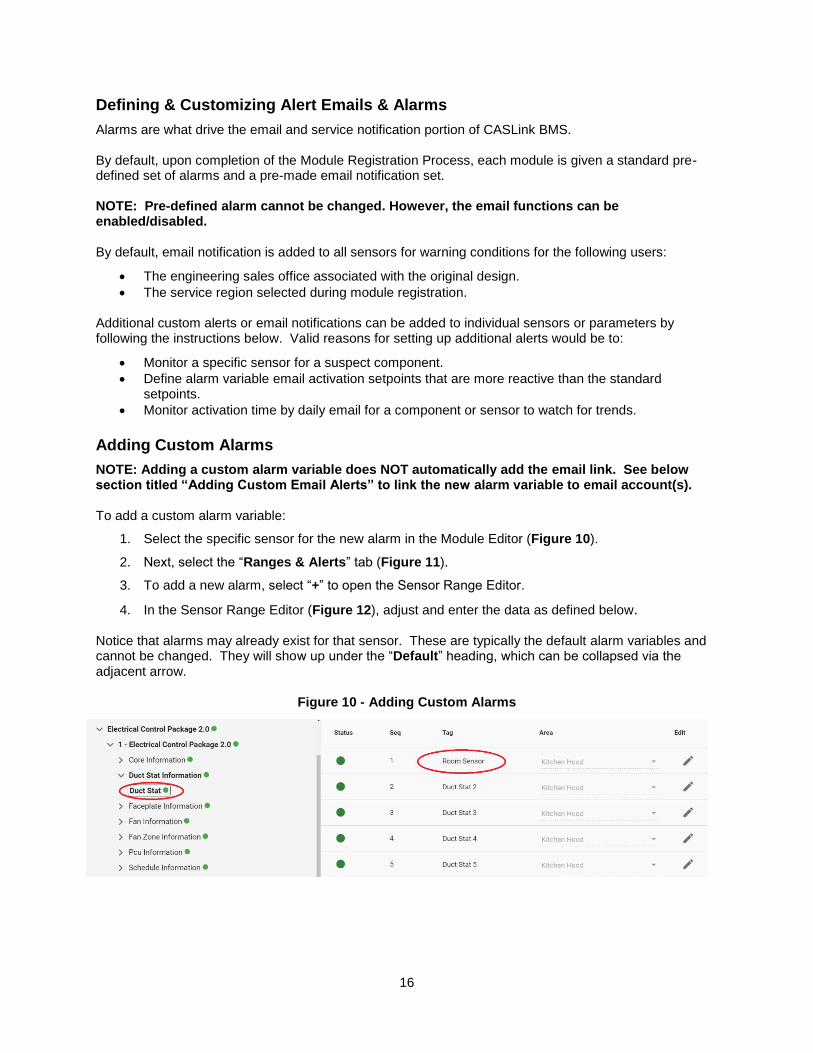
Adding Custom Alarms
NOTE: Adding a custom alarm variable does NOT automatically add the email link. See below section titled “Adding Custom Email Alerts” to link the new alarm variable to email account(s). To add a custom alarm variable:
1. Select the specific sensor for the new alarm in the Module Editor (Figure 10).
2. Next, select the “Ranges & Alerts” tab (Figure 11).
3. To add a new alarm, select “+” to open the Sensor Range Editor.
4. In the Sensor Range Editor (Figure 12), adjust and enter the data as defined below. Notice that alarms may already exist for that sensor. These are typically the default alarm variables and cannot be changed. They will show up under the “Default” heading, which can be collapsed via the adjacent arrow.
Figure 10 - Adding Custom Alarms
17
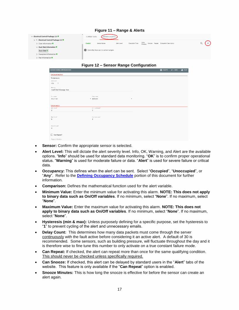
Figure 11 – Range & Alerts
Sensor: Confirm the appropriate sensor is selected.
Alert Level: This will dictate the alert severity level. Info, OK, Warning, and Alert are the available options. “Info” should be used for standard data monitoring. “OK” is to confirm proper operational status. “Warning” is used for moderate failure or data. “Alert” is used for severe failure or critical data.
Occupancy: This defines when the alert can be sent. Select “Occupied”, “Unoccupied”, or “Any”. Refer to the Defining Occupancy Schedule portion of this document for further information.
Comparison: Defines the mathematical function used for the alert variable.
Minimum Value: Enter the minimum value for activating this alarm. NOTE: This does not apply to binary data such as On/Off variables. If no minimum, select “None”. If no maximum, select “None”.
Maximum Value: Enter the maximum value for activating this alarm. NOTE: This does not apply to binary data such as On/Off variables. If no minimum, select “None”. If no maximum, select “None”.
Hysteresis (min & max): Unless purposely defining for a specific purpose, set the hysteresis to “1” to prevent cycling of the alert and unnecessary emails.
Delay Count: This determines how many data packets must come through the server continuously with the fault active before considering it an active alert. A default of 30 is recommended. Some sensors, such as building pressure, will fluctuate throughout the day and it is therefore wise to fine tune this number to only activate on a true constant failure mode.
Can Repeat: If checked, the alert can repeat more than once for the same qualifying condition. This should never be checked unless specifically required.
Can Snooze: If checked, this alert can be delayed by standard users in the “Alert” tabs of the website. This feature is only available if the “Can Repeat” option is enabled.
Snooze Minutes: This is how long the snooze is effective for before the sensor can create an alert again.
Figure 12 – Sensor Range Configuration

18
Adding Custom Email Alert Events
To add a custom email alert event, first select the alarm variable in the Module Editor (default or custom type are allowed) which is being used to activate the email. Select the specific sensor for that alarm (Figure 10).
1. Select the “Range & Alerts” tab (Figure 13).
2. Select the “Three Bar” icon. An “Alerts” pop up appears.
3. Add the email addresses, email type as necessary. Select “Add Email” (Figure 14).
4. Select “Save” button when complete (Figure 15).
5. The new alert event should now be shown in the “Ranges & Alerts” tab. Activation and deactivation of the email alert event can be done via the checkbox.
NOTE: This is a permanent deactivation and should not be used when a snooze command will suffice.
Figure 14 – Add Email
Figure 15 - Sensor Range Alerts Window after Email Has Been Added
Figure 13 - Adding Email Alerts
19
End User Guide
The alerts, zones, and customized events explained in the preceding sections should be set up by a CASLink service or sales representative. The end-user (i.e. restaurant owner, manager, or employee) can access CASLink by logging in with the account provided by CASLink service or sales representative. The following sections describe ways to access and interpret the information gathered through CASLink.
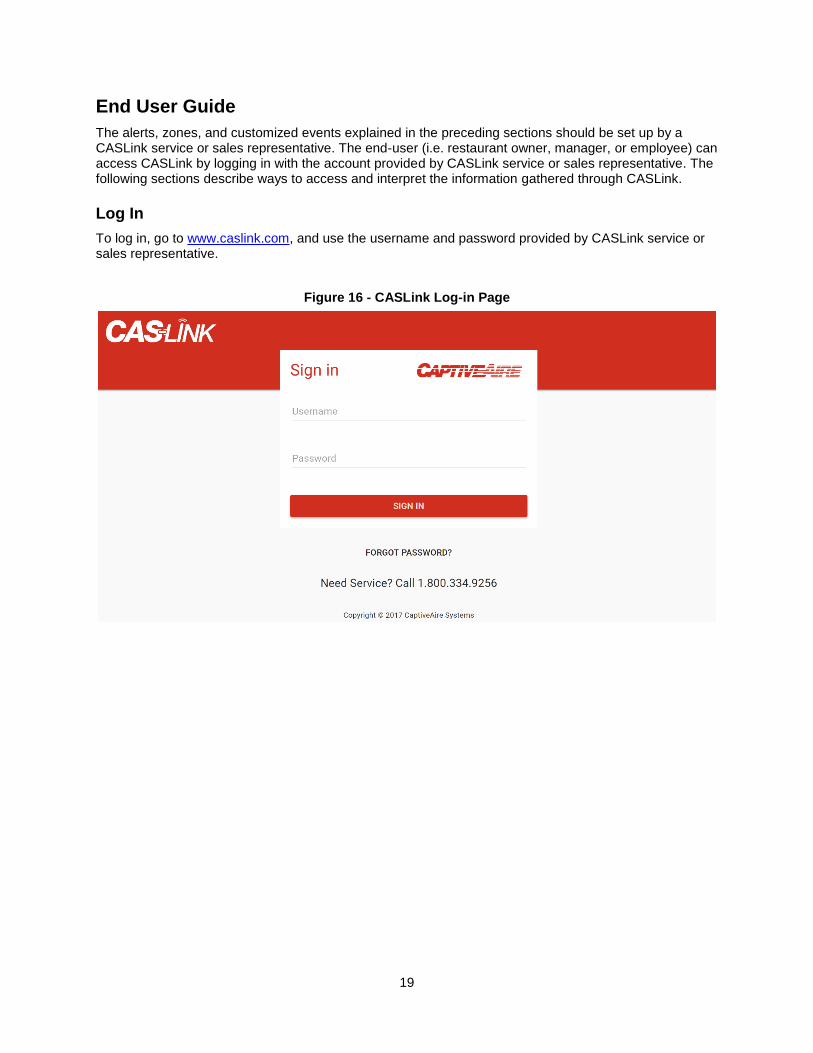
Log In
To log in, go to www.caslink.com, and use the username and password provided by CASLink service or sales representative.
Figure 16 - CASLink Log-in Page

20
Main Page Navigation
Immediately after signing in, the main CASLink page will appear. The search bar at the top of the page allows the user to load their site by searching the name or location in the search bar. If you have multiple locations they will appear in the dropdown menu. Once the page has loaded the monitoring, control and analytical buttons will appear the left hand side of the screen. There are multiple sections, each highlighted either in green (if there are no alerts), yellow (if there are non-critical alerts), red (if there are critical alerts that need immediate attention), or grey (if section is not available). The primary sections are:
1. Monitoring: Contains sensor values, alerts and graphs 2. Analytics: Contains graphs and interpretations of sensor data 3. Control: Used to control certain functions/scheduling of events
Figure 17 - CASLink Home Page
Figure 18 - Indication of a Critical Alert in a Sensor Area

21
Monitoring
The Monitoring section of CASLink shows all sensor areas that were setup for that specific location. To view current sensor values, click on any of the sensor areas shown.
Figure 19 - Sensor Areas shown in the Monitoring section

22
CORE Fire Protection
If there is one or multiple CORE fire systems (Hood or PCU) connected to a communication module, then the following conditions can be monitored at all times:
1. Fire Status: Reports Fire Condition.
2. Wash Solenoid Malfunction: Alerts user if plenum and duct water system solenoid is malfunctioning.
3. Appliance Solenoid Malfunction: Alerts user if appliance protection fire system solenoid is malfunctioning.
4. Microcontroller Fault: Reports an alert if circuit board is malfunctioning.
5. Surfactant Pump Malfunction: Alerts if there is a problem with the surfactant pump.
6. Supervised Loop Issue: Reports issue with Pull/Push station and/or fire sensor connections.
7. Ground Fault: Reports issue with Pull/Push station and/or fire sensor connections.
8. Surfactant Low: Alerts when surfactant level is below 50%.
9. Battery Voltage Low: Alerts if backup battery voltage is low.
10. AC Power Failure: Alerts if there is a problem with feeding power line.
11. Door Panel Open: Triggers alarm if CORE door panel is opened when the system is armed.
12. Test Mode: Reports if CORE system is currently on Test Mode.
13. Network Communication Error: Reports an issue with the CORE interlock network.
14. Fire Suppression System Activated by Fire Sensor: Alerts user if CORE has activated based on temperature readings.
15. Fire Suppression System Activated by Button: Alerts user if CORE has activated by push station.
16. Gas Is On: Reports if the gas line to the appliances is open.
17. Successful Wash Has Not Occurred: Alerts user if a wash has not occurred in 24 hours.
18. Washing: Reports when hot water wash is active. For further reference to these conditions, please consult the CORE Fire Protection manual.
Figure 20 - CORE Monitoring Parameters and Alert Screen
23
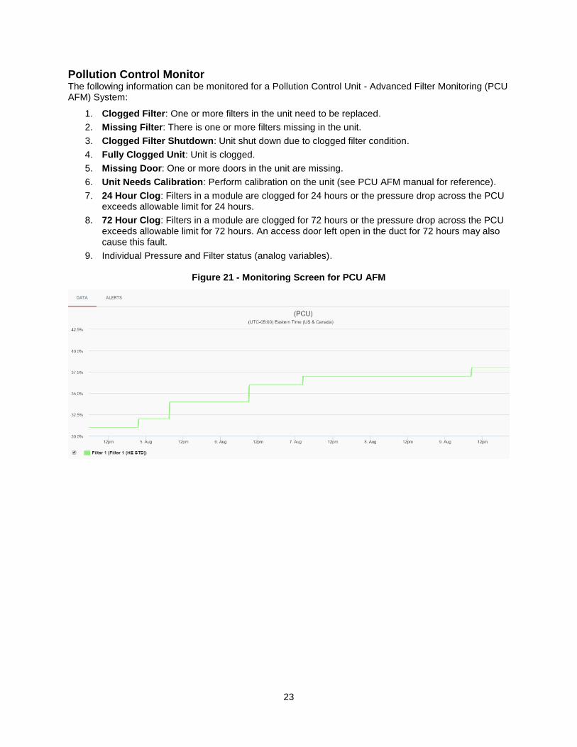
Pollution Control Monitor The following information can be monitored for a Pollution Control Unit - Advanced Filter Monitoring (PCU AFM) System:
1. Clogged Filter: One or more filters in the unit need to be replaced.
2. Missing Filter: There is one or more filters missing in the unit.
3. Clogged Filter Shutdown: Unit shut down due to clogged filter condition.
4. Fully Clogged Unit: Unit is clogged.
5. Missing Door: One or more doors in the unit are missing.
6. Unit Needs Calibration: Perform calibration on the unit (see PCU AFM manual for reference).
7. 24 Hour Clog: Filters in a module are clogged for 24 hours or the pressure drop across the PCU exceeds allowable limit for 24 hours.
8. 72 Hour Clog: Filters in a module are clogged for 72 hours or the pressure drop across the PCU exceeds allowable limit for 72 hours. An access door left open in the duct for 72 hours may also cause this fault.
9. Individual Pressure and Filter status (analog variables).
Figure 21 - Monitoring Screen for PCU AFM
24
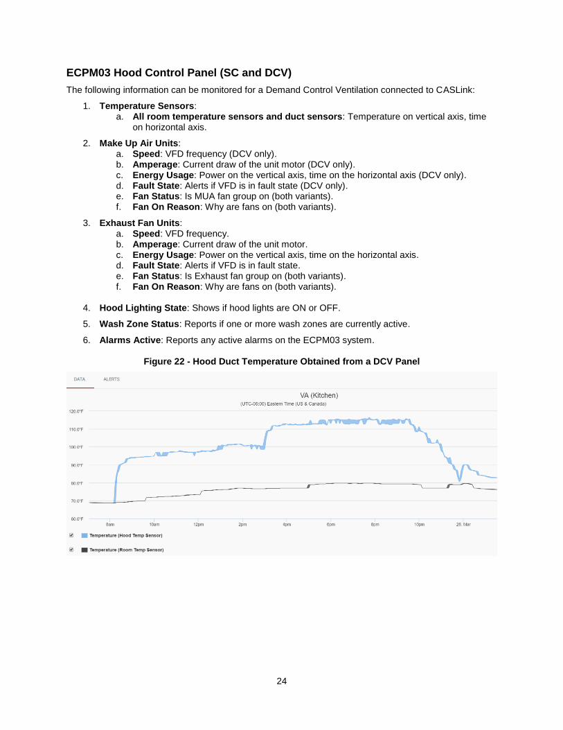
ECPM03 Hood Control Panel (SC and DCV)
The following information can be monitored for a Demand Control Ventilation connected to CASLink:
1. Temperature Sensors: a. All room temperature sensors and duct sensors: Temperature on vertical axis, time
on horizontal axis.
2. Make Up Air Units: a. Speed: VFD frequency (DCV only). b. Amperage: Current draw of the unit motor (DCV only). c. Energy Usage: Power on the vertical axis, time on the horizontal axis (DCV only). d. Fault State: Alerts if VFD is in fault state (DCV only). e. Fan Status: Is MUA fan group on (both variants). f. Fan On Reason: Why are fans on (both variants).
3. Exhaust Fan Units: a. Speed: VFD frequency. b. Amperage: Current draw of the unit motor. c. Energy Usage: Power on the vertical axis, time on the horizontal axis. d. Fault State: Alerts if VFD is in fault state. e. Fan Status: Is Exhaust fan group on (both variants). f. Fan On Reason: Why are fans on (both variants).
4. Hood Lighting State: Shows if hood lights are ON or OFF.
5. Wash Zone Status: Reports if one or more wash zones are currently active.
6. Alarms Active: Reports any active alarms on the ECPM03 system.
Figure 22 - Hood Duct Temperature Obtained from a DCV Panel

25
Control
The Control section of CASLink shows all sensor areas that have capability to be controlled through CASLink UI. To view each piece of hardware that has control capabilities, click on the “Control” icon from the home page.
RTULink
The following RTU information can be monitored for every RTU that has an RTULink board installed in it.
1. Temperature Sensors: a. Discharge Temperature b. Return Temperature c. Outside Air Temperature d. Space Temperature (if installed)
2. Unit Activity: a. Blower Status b. Individual Cooling Stage Status c. Individual Heating Stage Status d. Unit Alarm Status e. Cooling Setpoint (if in Full Control mode) f. Heating Setpoint (if in Full Control mode)
3. Faults/Alarms: Reports any fault that is active on the RTULink control board or any fault that is configured through CASLink.
Figure 23 - Cooling Setpoint Graph Obtained from RTULink Board

26
Navigating Sensor Data
All continuous time data (temperatures, fan speeds, energy usage, and amperage) will be shown in graphs with time on the horizontal axis. The time frame viewable can be modified using the Zoom functions shown above the graph (Set View Range, Zoom Out, Reset Zoom). You may select multiple sensors on the left hand side to overlay on the graph. Use the Start/Stop Multi Selection button to select sensors. Once selected the sensor information will appear on the graph. Zooming in on a selected area of the graph is accomplished by clicking on a start time and dragging the mouse to an end time before releasing the click.
Figure 24 - Overlapping Sensor Data on Same Plot
Figure 25 - Set Range and Export Tabs Shown Above Graph
27
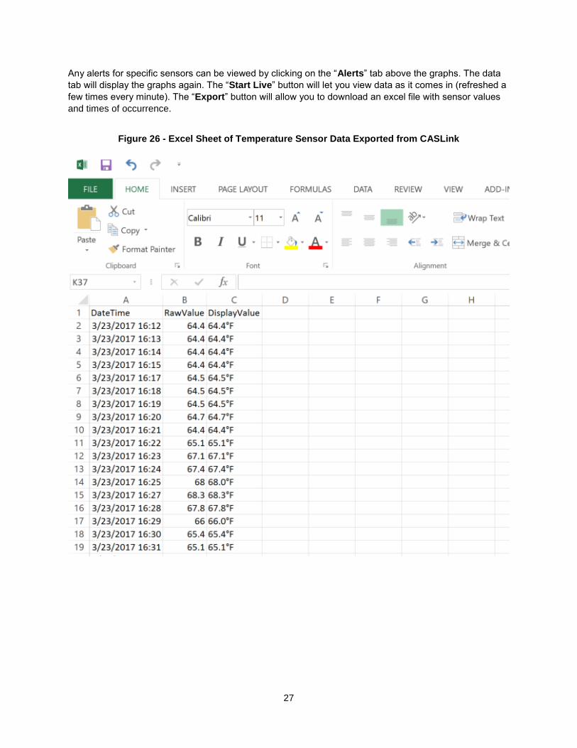
Any alerts for specific sensors can be viewed by clicking on the “Alerts” tab above the graphs. The data
tab will display the graphs again. The “Start Live” button will let you view data as it comes in (refreshed a
few times every minute). The “Export” button will allow you to download an excel file with sensor values
and times of occurrence.
Figure 26 - Excel Sheet of Temperature Sensor Data Exported from CASLink

28
RTULink Control Board
If the RTULink board is in Full Control or External Control Mode, it is capable of being controlled through CASLink. The Full Control Mode offers the highest level of control, allowing setpoints and settings of each RTU to be changed and controlled through CASLink. External Control Mode offers limited control of each RTU, with the majority of the operation still being controlled by an external thermostat. The Passthrough Control Mode offers no control capability and, as a result, the CASLink Controls interface will not be accessible. Each RTULink board will have a dashboard that appears in the Controls Area. The color of each individual dashboard indicates the current operation of the unit. A dashboard with a blue background means the unit is cooling and a dashboard with a red background indicates a unit is heating. In Figure 27:
The yellow box shows the heating setpoint (to the right of the red bubble), the cooling setpoint (to the right of the blue bubble), and the blower mode (a rotating fan means the blower is in ON mode and the absence of a fan means the blower is in AUTO mode).
The red box indicates the spot on the dashboard where the space, return, outside, and discharge temperatures are displayed.
The green box indicates the status of certain unit options. For example, if the emergency heat is ON or OFF, if the economizer is allowed, if the unit is in an occupied or unoccupied state, etc.
Figure 27 - RTULink Dashboard
The three links at the bottom of the RTULink dashboard are Schedule, Thermostat, and Settings.

29
Schedule
The scheduling UI is where the 7-day schedule is set for each board. Click and drag over an area of the schedule and release the click to highlight an area of the scheduler (press, drag and release for a touchscreen). Once an area has been highlighted, a popup will ask to create a new setpoint or to use an existing setpoint. An example of this popup can be seen in Figure 28. If no setpoints have ever been created, it will only give the option to create a new one.
Figure 28 - Setpoint Popup
30
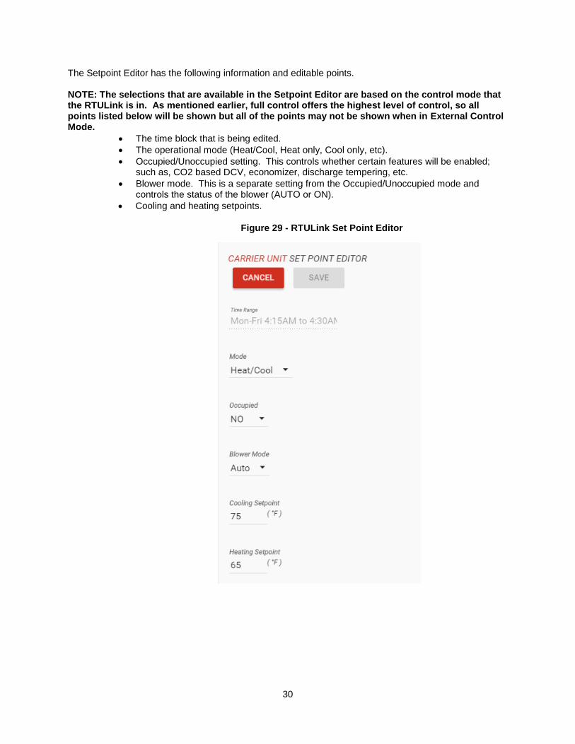
The Setpoint Editor has the following information and editable points. NOTE: The selections that are available in the Setpoint Editor are based on the control mode that the RTULink is in. As mentioned earlier, full control offers the highest level of control, so all points listed below will be shown but all of the points may not be shown when in External Control Mode.
The time block that is being edited.
The operational mode (Heat/Cool, Heat only, Cool only, etc).
Occupied/Unoccupied setting. This controls whether certain features will be enabled; such as, CO2 based DCV, economizer, discharge tempering, etc.
Blower mode. This is a separate setting from the Occupied/Unoccupied mode and controls the status of the blower (AUTO or ON).
Cooling and heating setpoints.
Figure 29 - RTULink Set Point Editor
31
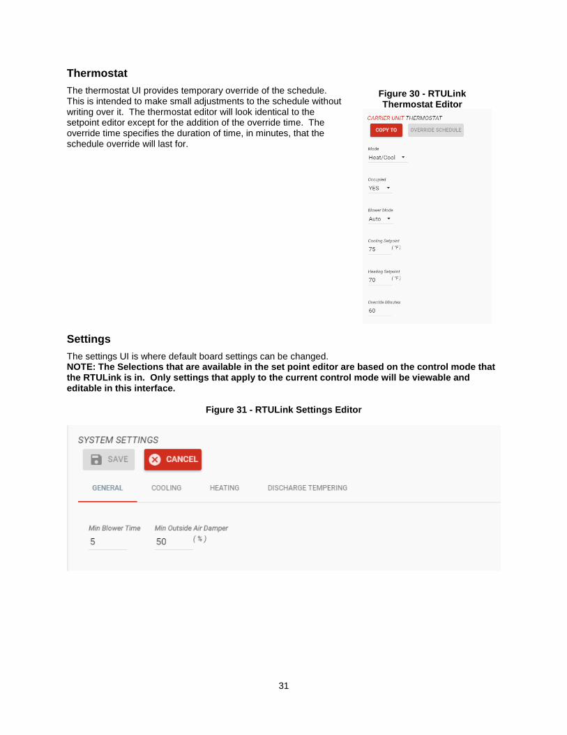
Thermostat
The thermostat UI provides temporary override of the schedule. This is intended to make small adjustments to the schedule without writing over it. The thermostat editor will look identical to the setpoint editor except for the addition of the override time. The override time specifies the duration of time, in minutes, that the schedule override will last for.
Settings
The settings UI is where default board settings can be changed. NOTE: The Selections that are available in the set point editor are based on the control mode that the RTULink is in. Only settings that apply to the current control mode will be viewable and editable in this interface.
Figure 31 - RTULink Settings Editor
Figure 30 - RTULink Thermostat Editor

32
MAINTENANCE
The CASLink Building Management System and Protocessor/ProtoNode modules, by their very nature, do not require physical maintenance unless a communication problem occurs. If changes are made to the jobsite between standard 6 month checkup intervals for other equipment such as the fans, fire system, etc. CASLink or Building Management Menus should be updated to reflect those changes. Please record the Module Mac address, BAUD rates, Authentication Key, End User information and Module data in the Start-Up table, and present this manual to the end-user upon completion.
Module Registration Parameter Documentation
Record Initial Settings & upload settings to Service Job Notes using System Design Verification Procedures.
Item Data
MAC Address
Authentication Key
BAUD Rate
Device ID
End User Email
End User Name
End User Password
CAS Service Region
CAS Technician
Phone
Factory Service Department
Phone: 1-866-784-6900 Fax: 1-919-554-9374