build the gears-ids trebuchetgearseds.com/files/trebuchet_rev2.pdf · build the gears-ids trebuchet...
TRANSCRIPT

Build the GEARS-IDS Trebuchet Build and Use the Trebuchet to Explore These Engineering and Physics Principles:
Mechanical Principles Bearings and Structures Levers
Science and Engineering Principles Force Mass and Motion Unbalanced Forces Work and Power Friction F=ma and Newton’s Laws of Motion Testing and Analysis Design and CAD
Design Principles Systems and Interactions Rigidity and Structures Threaded Fasteners
Mathematics Create and Use Basic Mathematical Models to
Evaluate and predict Component Performance Assess Performance Algebraic and Geometric Manipulations
History of Science and Technology The Genesis of Engineering Siege Engines
Personal and Interpersonal Skills Acquires and Evaluates Information Allocates and Organizes Time and Materials
NOTE: GEARS-IDS Components can be used to construct mechanisms that demonstrate physical science principles. These mechanisms allow students to experiment with simple machines,
DESIGN/BUILD/TEST/ PLAY Use The GEARS-IDS Invention and Design System to build and study trebuchets. Trebuchets were powerfully effective medieval siege engines that battered enemy fortifications with large masses of rock hurled hundreds of feet. The people who designed and built these and other siege engines were called Ingeniators (Engineers). Designing, building and using a trebuchet is an excellent engineering exercise. There are many variables that affect the trebuchet’s performance, andthus, there are many solutions. Multiple solutions provide young engineers with many \creative opportunities to develop science, math and engineering insights through the iterative process of experimenting, building, modifying and playing the trebuchet’s they design and build.
1
investigate work power and energy or construct devices that demonstrate the effects of force and motion.

DESIGN – BUILD – TEST - PLAY
Performance Tip. Before beginning any project, it helps to have a sense of what the beginning, middle and end of the project looks like. For Best Results Read the Entire Document Before Beginning
The Trebuchet can be built in less than 45 min. by a team of 2-3 people. Each team member can build 1 or more of the subassemblies (2 frames, 1 lever arm assembly) from which the trebuchet is constructed. Performance Tip. Engineering is a team sport. Be an engineering MVP. Accept and commit to completing specific responsibilities.
1. Obtain and organize the Tools and Materials (Listed below) 2. Build one or more of the subassemblies (Illustrated in this document) 3. Integrate the subassemblies into a working trebuchet. 4. Test and experiment with different sling lengths, counter weight arm lengths, launch angles and
throwing arm lengths.
Caution: Always wear safety glasses when working on, testing or using trebuchet models
2Gears LLC 105 Webster St. Hanover Massachusetts 02339 Tel. 781 878 1512 Fax 781 878 6708 www.gearseds.com

Organize the Tools and Materials The trebuchet can be completed quickly and with minimal frustration and mistakes by taking the time to read through the directions and readying the necessary tools and materials before beginning the assembly. Required Tools Safety Glasses 2-3 Phillips Head Screwdrivers 5/16” Combination Wrench (For the Stand Offs) 3/8” Combination Wrench 6” Needle Nose Pliers
5/64, 6/32 Allen Wrenches or Hex Keys Dial Calipers and Tape Measures
Materials Use the GEARS-IDS online catalog of parts and components to identify the following components. Structural Components 1 6x9 Flat Plates GIDS-SC-10002 8 13 Hole Angles GIDS-SC-10006 2 17 Hole Flat Bars GIDS-SC-10001-17 2 11 Hole Flat Bars GIDS-SC-10001-11 2 9 Hole Flat Bars GIDS-SC-10001-7 2 7 Hole Flat Bars GIDS-SC-10001-7 2 5 Hole Flat Bars GIDS-SC-10001-5 1 3” Hex Wheel GIDS-SC-10014 1 4” x 3/16 Axles GIDS-SC-10018 1 3/16” Hex Adapter GIDS-SC-10013-1875 1 ½” Shaft Collar 4 3/16” Shaft Collars 2 Sine Triangles GIDS-SC-1005 4 90 Degree Fish Plates GIDS-SC-1004-90
Hardware 40+/- #10-24 x 3/8” PH Machine Screws 6 #10-24 x ¾ PH Machine Screws 50+/- #10 Nuts and Lock washers Miscellaneous Supplies and Materials 1 or 2 12 ounce lead ball fishing weights 1 or 2 wood balls, 1” in diameter. Masons line or heavy string Thread Paper clips or 1/32” welding rod
Performance Tip. Go to www.gearseds.com to download a complete catalog and description of GEARS-IDS Invention and Design System components. This will help you locate the parts. Construct the Trebuchet using these Subassemblies Note: 2 assemblies are required for the right and left side frames 1. Base Plate 2. Left and Right Frames 3. Lever Arm Assembly 4. Counter Weight 5. Projectile and Sling 6. Cross Bracing
3
Gears LLC 105 Webster St. Hanover Massachusetts 02339 Tel. 781 878 1512 Fax 781 878 6708 www.gearseds.com

SBNL S IpAf
Base Plate with 4 Fish Plates
tep 1 ase Plate Assembly
ote: Use #10-24 x 3/8” machine screws with a flat washer, star washer and #10-24 nut on every connection. eave the setscrews loose until the final assembly.
tudy the illustration and align and mount the 90 degree fish plates as indicated in the illustration above.
t is possible to assemble the components in several different ways and still create a working trebuchet. This is articularly true regarding the selection and use of flat bars for cross bracing and the throwing arm assembly. s your familiarity with the components, and your knowledge of the operating principles that govern the
unction of the trebuchet grows, you will be able to customize and improve your trebuchet’s design.
Step 2 Assemble the Side Frames (2 required)4Gears LLC 105 Webster St. Hanover Massachusetts 02339 Tel. 781 878 1512 Fax 781 878 6708 www.gearseds.com
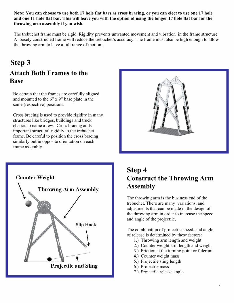
Note: You can choose to use both 17 hole flat bars as cross bracing, or you can elect to use one 17 hole
he trebuchet frame must be rigid. Rigidity prevents unwanted movement and vibration in the frame structure.
Step 3
and one 11 hole flat bar. This will leave you with the option of using the longer 17 hole flat bar for the throwing arm assembly if you wish. TA loosely constructed frame will reduce the trebuchet’s accuracy. The frame must also be high enough to allow the throwing arm to have a full range of motion.
Attach Both Frames to the
Step 4 Construct the Throwing Arm
he throwing arm is the business end of the
of
The combination of projectile speed, and angle of release is determined by these factors:
ight
Assembly Ttrebuchet. There are many variations, and adjustments that can be made in the design the throwing arm in order to increase the speedand angle of the projectile.
1.) Throwing arm length and weight 2.) Counter weight arm length and we3.) Friction at the turning point or fulcrum4.) Counter weight mass 5.) Projectile sling length 6.) Projectile mass 7 ) Projectile release angle
Be certain that the frames are carefully aligned
ross bracing is used to provide rigidity in many
g
and mounted to the 6” x 9” base plate in the same (respective) positions. Cstructures like bridges, buildings and truck chassis to name a few. Cross bracing adds important structural rigidity to the trebuchetframe. Be careful to position the cross bracinsimilarly but in opposite orientation on each frame assembly.
Base
5Gears LLC 105 Webster St. Hanover Massachusetts 02339 Tel. 781 878 1512 Fax 781 878 6708 www.gearseds.com

6
Exploded View of the Throwing Arm Assembly
Construct the Throwing Arm Assembly Note: L
eter axle ut 3/8” from the far end.
ter of the shaft. Do not tighten the
.) Attach an 11 hole flat bar to the 3” hex wheel, directly opposite to the 9 hole flat bar. Use two #10-
10-24 x ½” machine screws.
eave the screws and nuts loose until the final assembly.
1.) Select a 4” x 3/16” diam2.) Slide a 3/16” shaft collar onto the axle, abo3.) Slide a hex adapter with a 3/16” bore onto the (approximate) cen hex adapter set screws. 4.) Slide a 3” hex wheel onto the hex adapter. 5.) Secure the 3” hex wheel with a ½” shaft collar as shown above. 6.) Slide a 3/16” shaft collar onto the axle, about 3/8” from the near end. 7.) Attach a 9 hole flat bar to the 3” hex wheel using two #10-24 x ½” machine screws 8 24 x ½” machine screws to attach it to the 3: hex wheel. 9.) Attach either a 17 or 11 hole flat bar to the 11 hole flat bar using two #
Gears LLC 105 Webster St. Hanover Massachusetts 02339 Tel. 781 878 1512 Fax 781 878 6708 www.gearseds.com

the throwing arm assembly to the trebuchet frame by gently spreading the frame sections
end of the axles to secure the throwing arm assembly to the frame.
Note: For best results, do not use the hex adapter set screws. Allow the hex adapter and wheel assembly le makes a better bearing assembly than the axle
ht
ng
ttach the counter weight in a manner that will secure it hile allowing it to owing arm assembly.
ent Which of t ll throw a given projectile a further
1.) nter weight is rigidly affixed to the throwing arm.
2.) The Counter weight is allowed to hang freely froabove.
slight adjustments to the shape and angle of the slip hook, aadjustment. It often takes 100 or more test launches in ordeassembly, projectile sling length and projectile weight for o
10.) Attach and positioning the axles in the top holes of the sine triangle pieces. 11.) Use a 3/16” shaft collar on each 12.) Use the shaft collars to position the wheel and arm assembly, and secure it in place in a such a manner as to reduce side play.
to rotate on the axle. The hex adapter turning on the axturning on the holes in the sine triangle components.
Step 5 Attach the Counter Weig The GEARS-IDS Trebuchet works well with a counterweight of 8 – 16 ounces or 224 - 448 grams. Attach the counter weight to the throwing arm assembly usimasons line, fishing line or a paper clip. Be certain to afrom breaking away during use wwing freely on the end of the thrs
Suggested Experim
he following widistance, and why?
The Cou
SteAttCauswinwhe The weldto fo Attaa #1
The shape and angle of the slip hook controls the angle of r
G ears LLC 105 W ebster St. Hanover M assachusetts 02339 T
m the throwing arm as shown in the illustration
p 6
7
glasses
a paper clip,
t.
For best performance, make nd test the flight of the projectile after every r to “Tune” the counter weight, throwing arm ptimum performance.
ach the Slip Hook tion: The slip hook is a sharp pointed object ging on the end of a shaft. Always use safety n working on or testing the trebuchet!
slip hook can be fashioned froming rod or similar materials. Use needle nose pliers rm the hook.
ch the slip hook to the end of the throwing arm using0-24 x 3/8” machine screw, flat washer and nu
elease of the projectile.
el. 781 878 1512 Fax 781 878 6708 www.gearseds.com

Step 7 Assemble the Projectile and Sling
unces). The sling is a fine thread with a loop n one end.
he projectile and sling length can range between
g is attached to the wooden ball in one of two ways.
1.)
nd through the hole and knotting it to
2.) Tape the sling to the ball.
th
The projectile is round wooden ball approximately 1” (25.4 mm) in diameter and weighing approximately 5 grams (0.18 oo T The slin
Attach the sling by drilling a small, 1/32” holethrough the wooded ball and passing the non looped ethe ball
SA Tthmabf Tbo Thp
Remember: A rigid frame will ensure consistently accurate tconstructed will allow the throwing arm to release the projectilframe that twists will induce right and left (azimuth) angle erroare referred to as azimuth angles. Angular rotations along the
ngles. A right or left angle error of 5 degrees will result in a 1
performance of your trebuchet can take many dozens of trials.
a Many builders elect to fasten their trebuchets to weighted woodmechanism and ensure repeat accuracy. Remember that engine
Gears LLC 105 Webster St. Hanover Massachusetts 02339 Tel. 78
8
events the e from twisting about the vertical (y) axis.
ing
ith e swing of the projectile or counter weight.
tep 8 dd the Lateral Cross Bracing
he final step in the trebuchet assembly is to add e lateral cross bracing. The trebuchet frame ust resist torsion (twisting) and racking forces
cting on all axis (x,y, and z). The lateral cross racing adds torsion rigidity and prram
he reason the lateral bracing was added last is ecause it can potentially interfere with the swf both the projectile and the counter weight.
ake precautions to ensure that the 5 and seven ole pieces used for the lateral cross bracing are ositioned in such a way as to not interfere w
hrows. A frame that is wobbly or loosely e at a different angle on every throw. A loose r. Angular rotations along the vertical or y axishorizontal or x axis are refe
rred to as altitude
.7 foot error over 20 feet!
ring is an iterative process and optimizing the
bases in order to further stabilize the e
1 878 1512 Fax 781 878 6708 www.gearseds.com

Using the GEARS-IDS Trebuchet The trebuchet is a gravity-powered class one lever mechanism. The potential energy of the raised counter weight is converted into kinetic energy as the weight falls. The disproportionate ratio between the counterweight lever arm length x the counterweight mass and the projectile lever arm length x the projectile mass, creates a significantly unbalanced force that acts to accelerate the projectile to a very high velocity in a very short period of time.
r grip.
weight.
od ball ith a total ball and sling length of 12” (305 mm).
projectile at an
istently hurls the projectile 18-20 feet 5.48 – 6 meters).
accurate throws of up to nd in excess of 25 feet or more.
lacerate an eye. Always wear safety glasses when working on,
Launching the Projectile:
1.) Attach the projectile and sling to the slip hook.
2.) “Cock” the trebuchet by pulling down and back on the projectile ball and raising the counter weight.
3.) Release the ball by gently and slowly releasing you
The GEARS-IDS Trebuchet pictured on the left uses a counter weight made from a 12 ounce (336 grams) round lead fishing
The projectile is a 5 gram (0.18 oz), 1” diameter wow The slip hook angle is set to release theangle of 45 degrees to the horizontal. This trebuchet cons( While this trebuchet design works well, it is in no way optimal. This design can be significantly improved. By experimenting with the variables listed in step 4 it should be possible to obtain consistently a CAUTION: The slip hook is an important component of the treprojectile is released from the throwing arm. The slip hook has
Gears LLC 105 Webster St. Hanover Massachusetts 02339 Tel. 781
9
e d
using or experimenting with a trebuchet.
buchet and it controls the angle at which th a sharp end that can scratch your skin an
878 1512 Fax 781 878 6708 www.gearseds.com
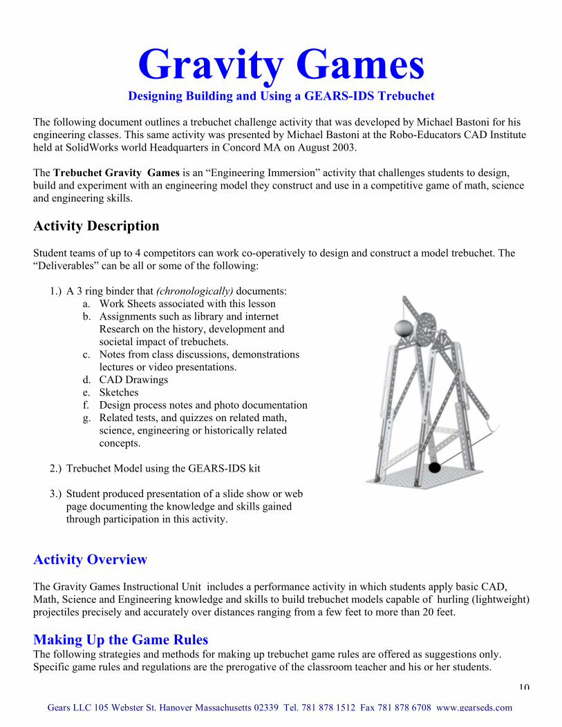
Gravity Games Designing Building and Using a GEARS-IDS Trebuchet
The following document outlines a trebuchet challenge activity that was developed by Michael Bastoni for his engineering classes. This same activity was presented by Michael Bastoni at the Robo-Educators CAD Institute held at SolidWorks world Headquarters in Concord MA on August 2003. The Trebuchet Gravity Games is an “Engineering Immersion” activity that challenges students to design, build and experiment with an engineering model they construct and use in a competitive game of math, science and engineering skills. Activity Description Student teams of up to 4 competitors can work co-operatively to design and construct a model trebuchet. The “Deliverables” can be all or some of the following:
1.) A 3 ring binder that (chronologically) documents: a. Work Sheets associated with this lesson b. Assignments such as library and internet
Research on the history, development and societal impact of trebuchets.
c. Notes from class discussions, demonstrations lectures or video presentations.
d. CAD Drawings e. Sketches f. Design process notes and photo documentation g. Related tests, and quizzes on related math,
science, engineering or historically related concepts.
2.) Trebuchet Model using the GEARS-IDS kit
3.) Student produced presentation of a slide show or web
page documenting the knowledge and skills gained through participation in this activity. Activity Overview The Gravity Games Instructional Unit includes a performance activityMath, Science and Engineering knowledge and skills to build trebucheprojectiles precisely and accurately over distances ranging from a few Making Up the Game Rules The following strategies and methods for making up trebuchet game ruSpecific game rules and regulations are the prerogative of the classroo
Gears LLC 105 Webster St. Hanover Massachusetts 02339 Tel. 781 878 15
in which students apply basic CAD, t models capable of hurling (lightweight)
feet to more than 20 feet.
les are offered as suggestions only. m teacher and his or her students.
10
12 Fax 781 878 6708 www.gearseds.com

1.) After thoroughly researching and discussing the subject of trebuchets, students create the specific
objectives, targets and game playing procedures. This is an appropriate strategy for high school classes. 2.) The teacher, working in cooperation with the students, develops game playing rules and constraints. 3.) The teacher considers the learning objectives and subject matter emphasis and creates a trebuchet
targeting game that best reinforces the material covered. 4.) Combinations of the above strategies.
Example Tournament Rules and Regulations for Gravity Games The Playing Field An unobstructed area of roughly 200 square feet with a minimum width of 10 feet and a minimum ceiling height of 8-10 feet (Higher is better). The playing field needs to accommodate all the students, and their trebuchet projects and still provide enough unobstructed space to play on. The Projectile Wooden balls can be purchased from hobby and craft stores or online at several locations. To locate online vendors use the keyword search “Wood Balls”. The Counter Weights Counter Weight Mass is restricted: Weights cannot exceed 16 ounces or 450 grams Creating The Target
1.) Tape 4, 81/2” x 11” letter size papers together to form a 17” x 22” sheet.
2.) Make 2 of these sheets 3.) Create the same form using 4 sheets of carbon paper. 4.) On one (1) sheet draw concentric circles with radii of:
a. 2” = 16 points b. 4” = 4 points c. 8” = 1 point
5.) In use, the target is made up of a “Sandwich” of three materials a. Concentric circle target face up. b. Carbon Paper c. 17” x 22 “ blank sheet
Note: The target point value rationale lends itself to a geometric app Game Playing Process
1.) A student team positions their (Completed) trebuchet on the floofrom the target are they choose.
2.) The team is allowed to make (1) a single “Ranging” shot, and thefloor with a dry erase marker or coin.
3.) After the ranging shot, the team is not allowed to move the targe
Gears LLC 105 Webster St. Hanover Massachusetts 02339 Tel. 781 878 1512
layered in this order:
lication of the inverse square law.
r of the playing field at any distance
shot contact point is marked on the
t or their trebuchet.
11
Fax 781 878 6708 www.gearseds.com

4.) The center of the target is placed over the shot
contact point and taped to the floor. The base of the trebuchet can also be taped to the floor. This is optional.
5.) The student team is given 5 (regulation) shots. As each shot contacts the surface paper, a blue carbon contact point is registered on the target sheet in contact with the carbon paper.
Scoring
1.) Scoring is based on the following algorithm. Developing the algorithm can be a creative experience, and there are absolutely no specific rules that govern the development of the scoring algorithm. The following scoring algorithm is offered as an example.
Feetin Target from Distance x Shots 5 of TotalPoint Score =
Note: Each student team is allowed to score only the 5 consecutive shots following the ranging shot. The ranging shot is not scored. Winning the Game The team with the highest point total wins the Gravity Games Competition. In the event of a tie, the game is decided by a sudden death play off. Each team is allowed 1 shot without benefit of a ranging shot. They are however, allowed to use a tape measure for their firing set up. Note: Many possibilities exist for creating a variety of game play and scoring strategies. Students and teachers are encouraged to create their own variations and add their own creative twists. Further Your Knowledge The web offers nearly limitless resources on how to build trebuchets, as well as historical information and sophisticated mathematical modeling tools that can help you optimize and engineer more performance from your trebuchet model, in less time. Take advantage of the opportunity to learn about the massive trebuchets designed and used by medieval engineers to lay siege to castles by spending an evening researching trebuchets on the web. It’s an enjoyable and informative use of your time, and it’s a great way to study the impact that engineering and technology have on culture and economy.
12
Gears LLC 105 Webster St. Hanover Massachusetts 02339 Tel. 781 878 1512 Fax 781 878 6708 www.gearseds.com