build instructions float kit - stevens aero
TRANSCRIPT
Float Kit
Fits Daddy-O (525)Length 29 in. | Width 3.5 in. | Finished Weight 10 oz. / pair
Version 1.0 (revised 05.12.2012)
Build Instructions
Daddy-O™ 525 Float Kit - Build Instructions. © 2012 Stevens AeroModel. All rights reserved.! Page 1

WARRANTY
Stevens AeroModel guarantees this kit to be free from defects in both material and workmanship at the date of purchase. This warranty does not cover any component parts damaged by use or modification. In no case shall Stevens AeroModel’s liability exceed the original cost of the purchased kit. Further, Stevens AeroModel reserves the right to change or modify this warranty without notice.
LIABILITY RELEASE
In that Stevens AeroModel has no control over the final assembly or material used for final assembly, no liability shall be assumed nor accepted for any damage resulting from the use by the user of the final user-assembled product. By the act of using the user-assembled product, the user accepts all resulting liability.
If the buyer is not prepared to accept the liability associated with the use of this product, the buyer is advised to return this kit immediately in new and unused condition to the place of purchase.
THIS PRODUCT IS NOT INTENDED FOR CHILDREN 12 YEARS OF AGE OR YOUNGER
WARNING: This product may contain chemicals known to the State of California to cause cancer and or birth defects or other reproductive harm.
PRODUCT SUPPORT
This product has been engineered to function properly and perform as advertised with the suggested power system and supporting electronics as outlined within this product manual. Product support cannot be provided nor can Stevens AeroModel assist in determining the suitability or use of electronics, hardware, or power systems not explicitly recommended by Stevens AeroModel.
For product assembly support, replacement parts, hardware, and electronics to complete this model please contact Stevens AeroModel on-line at www.stevensaero.com.
Stevens AeroModelPO Box 15347 - Colorado Springs, CO 80935 - USA
719-387-4187 - www.stevensaero.com
Build Instructions
Daddy-O™ 525 Float Kit - Build Instructions. © 2012 Stevens AeroModel. All rights reserved.! Page 2

Kit Inventory
☐ Laser cut wood (14 Sheets) See “Sheet Wood Inventory”☐ Build Instructions☐ Computer drawn detail sheets (4 sheets)☐ Pre-bent 3/32 in. wire struts (landing gear) (3 pcs.)☐ Pre-cut 3/32 in. dia. x 14-9/16 in. length wire spreader strut (1 pcs.)☐ Ply Float Bottoms “F25” (2 pcs.)
☐ Large Hardware Bag (4x6) 1 - 3/32 in. x 1 in. length Heat Shrink Tubing * 2 - 1/8 in. x 4 in. length Heat Shrink Tubing * ☐ Small Hardware Bag (2x3) 12 - Steel Landing Gear Straps 3017
24 - #2 x 1/4 in. Screw 3011
Suggested Items To Complete This Model
Many of the following items will be available at your local hobby shop. For your convenience Stevens AeroModel stocks most of the required and optional building supplies. If you have difficulties sourcing any of the requisite items locally, please visit our web site, at www.stevensaero.com, to purchase those items necessary to complete your model.
Covering Film Requirements
While any high quality model film may be used to finish this float set. Superior results will be achieved using a heavier grade of covering film with an aggressive iron on adhesive. We suggest using the Bright Silver Float Film available on our web site [SGX370]
☐ 1 - Roll (2M) Float Film - Bright Silver 2M x 800MM SGX370
Required Building Supplies and Tools
☐ 1/2 oz. Thin CA Glue [PAAPT09]☐ 1/2 oz. Medium CA Glue [PAAPT02]☐ 1 oz. Thick CA Glue [PAAPT20]☐ CA glue applicator tips [PAAPT21]☐ CA glue accelerator (kicker) [PAAPT15]☐ Balsa filler [HCAR3401]☐ Hobby Knife with ample supply of #11 blades☐ Sanding Block, Dual Grit [SB120240]☐ Heat Gun and Covering Iron☐ Medium Needle Nose Pliers☐ Masking Tape (Low tack “blue” painters tape)☐ #1 Phillips Head Screw Driver☐ Spray Clear Lacquer (or suitable wood
sealant)
Optional Building Supplies and Tools
☐ CA glue de-bonder [PAAPT16]☐ CA glue bottle Z-Ends [PAAPT18]☐ Long sanding bar
Build Instructions
Daddy-O™ 525 Float Kit - Build Instructions. © 2012 Stevens AeroModel. All rights reserved.! Page 3
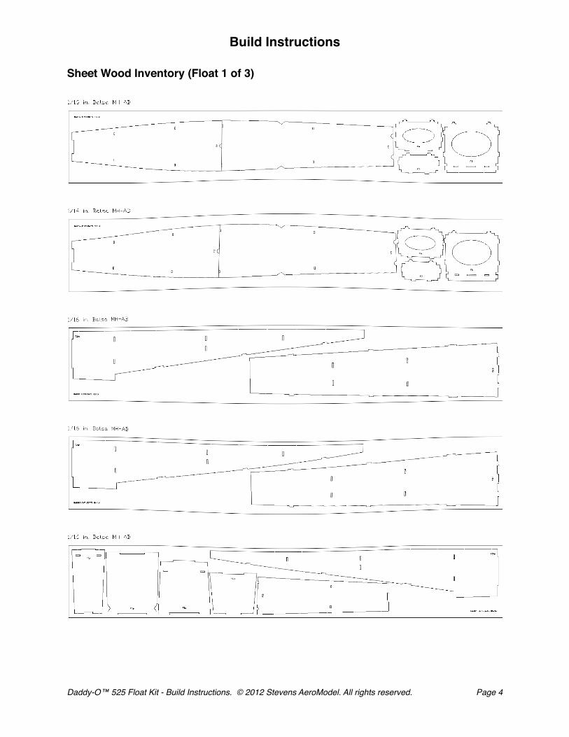
Sheet Wood Inventory (Float 1 of 3)
Build Instructions
Daddy-O™ 525 Float Kit - Build Instructions. © 2012 Stevens AeroModel. All rights reserved.! Page 4

Sheet Wood Inventory (Float 2 of 3)
Build Instructions
Daddy-O™ 525 Float Kit - Build Instructions. © 2012 Stevens AeroModel. All rights reserved.! Page 5
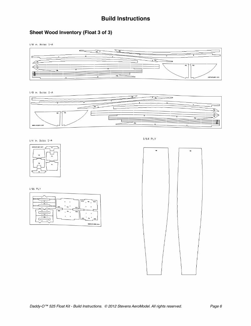
Sheet Wood Inventory (Float 3 of 3)
Build Instructions
Daddy-O™ 525 Float Kit - Build Instructions. © 2012 Stevens AeroModel. All rights reserved.! Page 6

General Assembly Instructions
Thank you, for purchasing this Stevens AeroModel Float Kit for the Daddy-O 525. This product has been developed and manufactured using state of the art CAD/CAM systems and features a unique interlocking construction process that, when compared to traditional methods found in other model aircraft kits, save countless hours of measuring, cutting, sanding, and fitting. We are certain that you’ll find our kit to offer a truly exceptional build experience. As this kit is recommended for the novice model builder and pilot; we invite beginners who have purchased this kit to seek the help of a seasoned builder and pilot. At any time should one run across a term or technique that is foreign please don’t hesitate to contact our staff with your questions.
READ THIS!
Please READ and RE-READ these instructions along with any other included documentation prior to starting your build and/or contacting our staff for builder support.
Pre-sanding
Do not skip this step. Prior to removing any parts from the laser cut sheet wood use a sanding block loaded with 250-400 grit paper and lightly sand the back side of each sheet of wood. This step removes any residue produced as a result of the laser cutting process and, as we have found that most stock wood sizes run several thousandths of an inch over sized, slightly reduces the thickness of each sheet.
Leave your pre-sanded parts in the sheet until required in the assembly process.
Protecting your worktable
Use the poly tube that this kit was shipped in as a non-stick barrier between your worktable and the product assembly.
Bonding the assembly
As this product tabs, notches, and otherwise interlocks like a 3D puzzle we suggest that when fitting parts you dry fit (use no glue) the parts together first. It’s advised to work 1-2 steps ahead in the instructions using this dry-fit technique which allows ample opportunity to inspect the fit and location of assembled components and realizes a benefit as each successive part contributes to pulling the entire assembly square. Once you arrive at the end of a major assembly sequence square your work on top of a flat building table and revisit the dry fit joints with glue. Using the dry-fit process you’ll be able to recover from a minor build mistake and will ultimately end up with a more square and true assembly.
Unless otherwise noted in the instructions we find it easier to tack glue part (temporarily bonding parts in assembly using a small dot of glue) using medium CA glue applied with a fine-tip CA glue applicator tip. Tight fitting joints should be bonded using thin CA glue applied, sparingly, with a CA glue applicator tip.
Never force the fit!
Remember this is a precision cut kit our machines cut to within 5 thousandths of an inch in accuracy. Yet the wood stock supplied by the mill may vary in thickness by up to 20 thousandths. This variance in the wood stock can cause some tabs/notches to fit very tight. With this in mind, consider lightly sanding, or lightly pinching, a tight fitting tab rather than crushing and forcing your parts together. You’ll break fewer parts in assembly and will end up with a more square and true airframe.
Manual Updates
Please check our web-site for updates to these instructions prior to commencing the build. To obtain downloads and updates relative to this model aircraft kit, please visit the corresponding product page at StevensAero.com
Build Instructions
Daddy-O™ 525 Float Kit - Build Instructions. © 2012 Stevens AeroModel. All rights reserved.! Page 7

Float Assembly
Float parts are designated with a “F” followed by a numeric. Parts have been numbered so that the float assembly and required parts follows in numeric order from F1 to F25. Assembly instructions and accompanying photos cover the building process for one float. Rather than building the second float in tandem, we suggest building the first float alone then repeating the necessary assembly steps to build a second float.
The Float is of traditional sheet wood and former assembly. Unless otherwise specified, formers should be installed with the etched part number facing the front of the assembly and any top or bottom designations followed.
You will dry fit the majority of this float assembly together only gluing at the final instructional steps. When parts cannot easily be retained with friction, use a single tiny drop of medium CA glue applied sparingly through a CA glue applicator tip to “tack glue” the part in place. Should you commit an error in assembly it will be easier to recover from the mistake and remove or correct the part fit in error if you do not slather the assembly in glue after each step! Further, this method of assembly will allow our interlocking design to do it’s job as each successive part installed within the float will help pull the entire structure square and true.
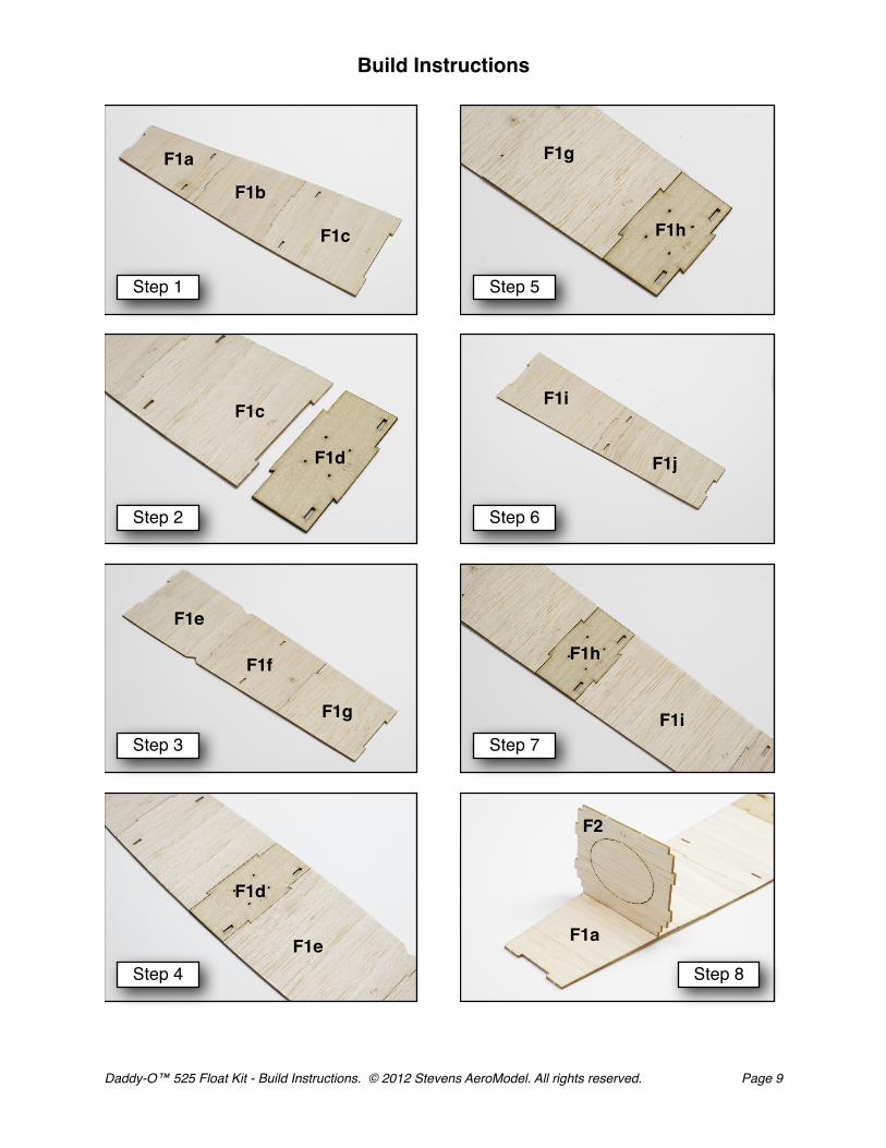
Construction begins with the top decking F1a-j. This part will be very fragile until cross grained in later steps. Handle this part with care and resist the urge to sand the glue joints as this will risk breaking the part.
1. Begin the top deck of the float by fitting and bonding parts F1a, F1b, and F1c together. Once again, as this deck assembly progresses it will, at first, be quite fragile and should be handled with great care. The assembly will become more manageable as the second layer of the deck is added over the first layer, cross graining it and making it quite stiff.
2. Fit and bond 1/16 ply wood part F1d to F1c.
3. Fit and bond parts F1e, F1f, and F1g together.
4. Fit and bond this assembly to the first, F1d to F1e.
5. Fit and bond ply part F1h to F1g, at the end of the assembly.
6. Fit and bond F1i and F1j together.
7. Fit this final assembly to the main assembly, bonding F1i to the ply part F1h.
8. Lay the deck assembly F1 flat on the table. Fit and tack glue former F2 to the slots in F1a. Tip: Leave the oval knock-out in formers for added strength during assembly. The tabs on the formers will protrude through F1, and will later receive the second layer of the deck. (See photo on page 12)
Build Instructions
Daddy-O™ 525 Float Kit - Build Instructions. © 2012 Stevens AeroModel. All rights reserved.! Page 8
☐
☐
☐
☐
☐
☐
☐
☐
Build Instructions
Daddy-O™ 525 Float Kit - Build Instructions. © 2012 Stevens AeroModel. All rights reserved.! Page 9
Step 1
F1a
Step 2
Step 3
Step 4
Step 5
Step 6
Step 7
Step 8
F1b
F1c
F1c
F1d
F1e
F1f
F1g
F1d
F1e
F1g
F1h
F1i
F1j
F1h
F1i
F1a
F2

Float Assembly Continued
9. Fit and tack glue remaining formers F3 through F7, in order, front to back. If the former doesn’t fit, it’s the wrong former in the wrong place. Ensure that all tabs protrude through to the other side of F1.
10. Carefully turn the assembly over (right side up). Test fit F8 to assembly, remove, then coat one side of F8 with thick CA and fit it over the tabs of F2 and F3 where they extend through F1. Turn assembly over again (up side down), and firmly press F1 and F8 together. Wipe up any glue that oozes out between the parts.
11. In the same manner, coat one side of F9 with thick CA and fit over the tabs of F4 and F5 where they protrude through F1. Turn the assembly up side down and press F1 and F9 together, wiping up any excess glue.
12. In the same manner fit and bond F10 to the tabs of F6 and F7. Turn assembly over and press together firmly.
Build Instructions
Daddy-O™ 525 Float Kit - Build Instructions. © 2012 Stevens AeroModel. All rights reserved.! Page 10
☐
☐
☐
☐

Build Instructions
Daddy-O™ 525 Float Kit - Build Instructions. © 2012 Stevens AeroModel. All rights reserved.! Page 11
Step 8 continued
F4
F8
F2
Step 9
Step 10
Step 10 continued.
Step 11
Step 11 continued.
Step 12
Step 12 continued
F3
F5
F6 F7
F9
F10
F2F3
F2
F3
F4
F5
F4
F5
F6
F7
F6
F7

Float Assembly Continued
13. Using medium CA glue, bond one each 1/8 in. balsa parts F11a and F11b along scarf joint (dotted line in illustration) to create part F11. Repeat for second set of F11a/b to create second part F11.
14. Fit one each part F11 to right and left side of float assembly as illustrated. Make certain the notches in F11 are completely seated with slots provided in formers F2 - F7. Note: You may tack glue F11 to retain, but only where the part interfaces the formers F2-F7.
Trivia! The parts being installed at this time are called gunwhales in boat speak, and are pronounced “gunnels”. In boats and ships, as in these floats, they are a major structural member and ensure that the vessel holds it’s designed shape.
15. Fit 1/4 in. balsa part F12 between right and left parts F11(a) and within notch at front of deck sheeting. Parts F11(a) should capture F12 and terminate flush with top of F12. Tack glue to retain F12 within assembly.
16. In the same manner as step above, fit 1/4 in. balsa part F13 between right and left parts F11(b) and within notch at back of deck sheeting. Parts F11(b) should capture F13 and terminate flush with top of F13. Tack glue to retain F13 within assembly.
17. Fit part F14 to the rear of the float atop F13, and flush with the ends of the float sides. Ensure that the notches in F14 face away from the top deck - allowing the bottom rails to lie in the notches in Step 28.
18. Invert assembly and Fit 1/8 in. balsa parts F15 to right and left of decking and “gunnels”, matching triangular tab in F15 to similar notch in F9 decking, and terminating at aft end of float. Now bond using a slow setting glue (thick CA) to allow ample working time in fitting and bonding this part to the float assembly.
19. In the same manner as step above, fit and bond F16 to the “gunnels” matching angled end of F16 to notch created between F15 and decking, and extending to terminate at the front of the float assembly.
20. Fit and bond 1/16 plywood part F17 between top deck sheeting at recess created by parts F8 and F9. Take note of the dashed are on illustration as this area must be removed in a later assembly step. Therefore we suggest that you DO NOT GLUE along the dashed area when retaining part F17.
Build Instructions
Daddy-O™ 525 Float Kit - Build Instructions. © 2012 Stevens AeroModel. All rights reserved.! Page 12
☐
☐
☐
☐
☐
☐
☐
☐

Build Instructions
Daddy-O™ 525 Float Kit - Build Instructions. © 2012 Stevens AeroModel. All rights reserved.! Page 13
Step 13
Step 15
Step 16
Step 17
Step 18
Step 19
Step 20F17
F11a
F11b
F11b
F11a
F11(a)F2
F3
F11
F11
F2
F12
F13
F7F11(b)
F11(b)
F11(a)
F13
F14
F7
F9
F10
F15
F15
F16F15
F9
F8
F16
F8
F9
NO GLUE!
Step 14
Aft
Front

Float Assembly Continued
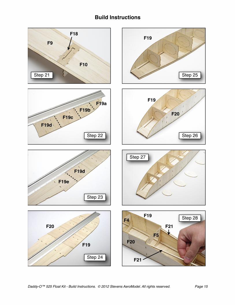
21. Fit and bond 1/16 plywood part F18 between top deck sheeting at recess created by parts F9 and F10.
22. Begin assembling the float side by fitting and bonding parts F19a, F19b, F19c, and F19d together. The top edge of the float side parts will form a straight line from top to tip. If a part alters this straight line, it is in up-side-down!
23. Fit and bond part F19e to F19d, ensuring that the top edge is a straight line.
24. Repeat “☐ ☐“ steps 23 and 24 to assemble second float side F20 from parts F20a through F20e.
25. Fit the completed side F19 to the float formers, beginning at F2 and working toward the rear of the float. Ensure that all tabs seat fully, and that there are no gaps between the float side and the formers. Tack glue the side to the formers at tab and notch locations. Now, work your way along the side and bond the side sheeting within the stepped portion of the “gunnels”.
26. Repeat “☐ ☐“ step 25 to fit and bond side F20 to float assembly.
27. If you elected to leave the oval knock-outs within the formers F2-F7, now is a good time to remove them.
Now, with the assembly up side down on a flat surface, final bond all mating surfaces with medium CA. Build up a small fillet inside the seams at the gunnels, deck, and sides, tab areas, and the seams between the deck and gunnels - any place water might get in. Hold the assembly between your eyes and a strong light. Check for gaps in any seam and fill with medium CA.
28. Fit the bottom rail (“chine” in boat speak) F21 to the notch in F5, resting in the notches at F6, F7, F14, and between float side. The forward edge of F21 will protrude slightly through former F5. The aft end should be flush with the aft edge of the float assembly. Note that the bottom edge of the float sides (F19 and F20) will stand proud of the rails by 1/16 in.
In the above manner fit both right and left parts F21 to assembly and bond in place where F21 contacts formers and float sides.
Build Instructions
Daddy-O™ 525 Float Kit - Build Instructions. © 2012 Stevens AeroModel. All rights reserved.! Page 14
☐
☐ ☐
☐ ☐
☐
☐
☐ ☐
☐
☐
Build Instructions
Daddy-O™ 525 Float Kit - Build Instructions. © 2012 Stevens AeroModel. All rights reserved.! Page 15
Step 21
Step 23
Step 24
Step 25
Step 26
Step 27
Step 28
F21
F21
F9
F10
F18
F19aF19b
F19c
F19d
F19e
F19
F20
Step 22
F19
F19
F20
F5
F19
F20
F4
F19d

Float Assembly Continued
29. Dry fit the rear bottom planking F22, tabbing into former F5, F6, F7, and float sides F19/F20. F22 should seat completely within the float sides. Check the fit, then remove F22. Coat F21 bottom rails or “chines” and the edges of formers F6 and F7 with thick CA. Replace F22, fitting it carefully in position. Wipe up any glue that oozes out of the seams. Form a small fillet of medium CA along the seam between F22 and former F5. Carefully inspect all the seams and tab notches, filling any gaps with medium CA.
30. Check the fit of F23 inside one side of the float. F23 should rest on the “gunnel”, against former F2 and float side F19. Important! The float side will stand proud above F23 by 1/32 in. Remove F23 and coat the mating surface (called the “faying surface” in boat speak) with thick CA and replace. Remove any glue that oozes out between F23 and the float side (especially where the side stands proud of F23 as this area must remain clear of glue and other imperfections to allow the bottom planking to lay flush within this 1/32 in. recess at the float sides).
Repeat process to install second F23 on opposite side of float resting along “gunnel”, against former F2 and F20 float side.
31. Fit a right and left bottom rail F24 to the notch in F23 and former F2. Align the rails so that the edge of F23 continues in a straight line into the edge of F24. When fitted properly, F24 will stand out from the body of the float at an angle (see second picture in Step 31 photo series). Bond with medium CA, the extreme forward end of F24, to F23 former F2 and the float side within the area circled. Do not bond behind F2.
Bend right and left F24 down, laying it in the notches between the formers and the float side. Tack glue F24 to the formers. Carefully align F27 along the edge of the float so that a 1/32 in. step is created between the float side and F24 (This is where the bottom sheeting will lie). Tack glue as you go. When all is to your satisfaction, final bond with thin CA.
32. Check the fit of the 1/64 in. thick plywood bottom planking F25, taping it in place with low tack masking tape. Remove F25, leaving the tape attached to the ply sheeting. Coat the rails, the edge of each former, and the tip of the float with thick CA and replace F25, taping back in place until the glue cures. Remove the tape, inspect the seams and fill any gaps with medium CA.
Note: When properly fit, F25 will sit slightly lower than float sides as F25 is made from 1/64 ply and the step we created was 1/32 in. This is intentional and any overhang of the float sides will be sanded away in the next step.
33. Sand the float smooth, rounding the top edges and leaving the bottom edges square.
34. Repeat the entire assembly sequence steps 1 - 33 to create a second identical float assembly.
Build Instructions
Daddy-O™ 525 Float Kit - Build Instructions. © 2012 Stevens AeroModel. All rights reserved.! Page 16
☐
☐
☐
☐
☐
☐

Build Instructions
Daddy-O™ 525 Float Kit - Build Instructions. © 2012 Stevens AeroModel. All rights reserved.! Page 17
Step 29
Step 30
Step 31
Step 31 Continued
Step 32
F22
F5
F23
F2F23
F24
F20
F20
F19
Step 31 Continued
F24F24
F24
F25
Round
Leave Bottom Square
Leave Bottom Square
Round
Step 33
Step 33 Continued
Bond Here
Maintain a 1/32 in. step along length of F24 at side of float.

Final Assembly
35. Lay the completed floats next to each other, and mark the inside faces with a felt tip marker or small piece of tape. You now have a ‘left’ and ‘right’ float. Using a sharp hobby knife remove the perforated section of F11 nearest the INSIDE edges of the floats. Proceed carefully, cutting through the tabs and prying the cut-out free of part F11.
36. Continue this slot by cutting a matching notch through the inside “gunnel”, no deeper or wider than the slot in F11.
37. Lightly spray the floats with several light coats of a clear lacquer. We recommend Deft® clear lacquer spray, available at most hardware stores. Sand the float lightly between coats, building up at least three coats of lacquer. When the floats are completely dry, give them one more light sanding. Using the templates provided on the detail sheets, cover the floats with a mid to heavy weight, high quality, iron on material.
38. Using a sharp hobby knife or single edge razor blade, remove the covering over the landing gear mount slots. The rear mount slots should have the covering removed over the recess on the inside of the float. This recess allows clearance for the middle landing gear brace.
39. The front mount should have the covering removed over the slot that you created in steps 31 and 32. This should be on the inside of the float, the same as the recess on the aft mount.
40. Check the pre-bent landing gear against the drawings on detail sheet #4. Using pliers, make any adjustments necessary until the gear angles match the drawings exactly. Identify each landing gear brace for use in the following steps.
41. The front landing gear wire and middle landing gear brace need to be “shimmed” to fit the slot in the front landing gear mount on the fuselage. Select the 1/8 in. length of heat shrink tube and cut into two equal lengths of 3-3/4 in. Slide one tube each over the front and middle landing gear wire until it is centered between the legs of the gear. Shrink the tubing with a heat gun on high heat.
42. The rear landing gear brace will also need to be shimmed. Cut two 3/8 in. lengths of heat shrink tube from the provided length of 3/32 in. heat shrink tubing. Slide these over the rear landing gear wire and position so that they will roughly align with the pre-drilled gear strap locations within the Daddy-O 525 fuselage. Shrink the tubing with a heat gun on high heat.
Build Instructions
Daddy-O™ 525 Float Kit - Build Instructions. © 2012 Stevens AeroModel. All rights reserved.! Page 18
☐
☐
☐
☐
☐
☐
☐
☐

Build Instructions
Daddy-O™ 525 Float Kit - Build Instructions. © 2012 Stevens AeroModel. All rights reserved.! Page 19
Step 35
F17
Step 36
Step 37
Step 38
Step 39
Step 40
Step 41
Step 42
F17
Inside
Inside
InsideInside
3/32 in. Tubing
1/8 in. Tubing

Final Assembly Continued
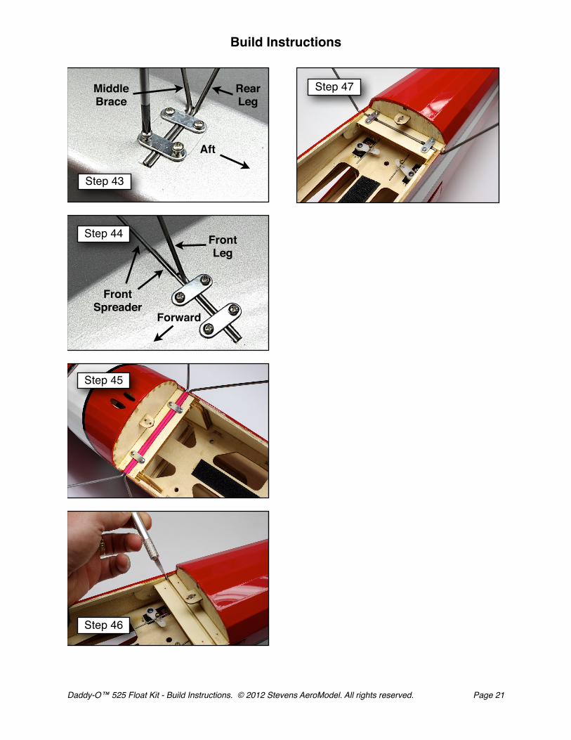
43. Open the covering over the four holes in each mount to receive the mounting screws. Fit the rear landing gear and the middle brace into the slot in the rear mount of each float. The rear landing gear should rest behind the middle brace within the slot, with the recess in the slot receiving the bend in the middle brace. Secure the landing gear and middle brace with two steel landing gear straps and four #2 1/4 in. screws in each mount.
44. In a similar manner, install the front landing gear and spreader. The spreader will rest in the slot you created on the inner edge of the float, with the landing gear wire resting aft of the spreader within the slot. Secure with two landing gear straps and four screws in each mount.
45. Position the front landing gear and middle brace within the front landing gear slot as illustrated. Install the two landing gear straps with four #2 x 1/4 in. screws.
46. Use a sharp #11 blade to open the covering on the right and left side of the rear lading gear slots. If necessary, touch this area up with a covering iron.
47. Fit the shimmed rear landing gear wire in the rear landing gear slot, centering it carefully within the slot. The heat shrink “shim” will stand proud of the slot slightly allowing the straps to compress it within the slot. Install two landing gear straps with four #2 x 1/4 in. screws.
48. Check your float alignment both from the front and sides of the model. The float should be parallel to each other and the fuselage.
Your Daddy-O™ (525) is now well equipped for sorties over the water. Re-check and adjust your CG as the floats may impact your model’s balance. Start out slowly on water learning how to perform low and high speed taxi’s prior to attempting your first flight.
We know you will enjoy many great flying sessions with your Daddy-O™ (525) on floats. Be certain to inspect and promptly repair any damage to avoid allowing moisture to infiltrate the float assemblies.
Thank You!
We hope you enjoyed this kit from Stevens AeroModel. Stevens AeroModel is committed to improving your build and flying experience and are constantly refining our processes, designs, and manuals to reflect customer feedback. You may correspond with our staff using any of the following methods:
E-Mail - [email protected]
RCGroups.com - Forum Build Threads
Facebook.com - Search for Stevens AeroModel
Phone - 719-387-4187
Build Instructions
Daddy-O™ 525 Float Kit - Build Instructions. © 2012 Stevens AeroModel. All rights reserved.! Page 20
☐
☐
☐
☐
☐
☐
Build Instructions
Daddy-O™ 525 Float Kit - Build Instructions. © 2012 Stevens AeroModel. All rights reserved.! Page 21
Step 43
Step 46
Step 47
Aft
RearLeg
MiddleBrace
FrontSpreader
FrontLeg
Forward
Step 44
Step 45