btm7, bts7 and bts7.1 stainless steel thermostatic … steel thermostatic clean steam traps...
TRANSCRIPT

IM-P180-05 CMGT Issue 13 1
BTM7
BTS7
BTS7.1
1. Safety information
2. General product information
3. Installation
4. Commissioning
5. Operation
6. Maintenance
7. Spare parts
© Copyright 2017
Printed in GB
IM-P180-05CMGT Issue 14
1801050/14
BTM7, BTS7 and BTS7.1 Stainless Steel Thermostatic Clean Steam Traps
Installation and Maintenance Instructions

IM-P180-05 CMGT Issue 132

IM-P180-05 CMGT Issue 13 3
1. General safety informationSafe operation of these products can only be guaranteed if they are properly installed, commissioned, used and maintained by qualified personnel (see Section 1.11) in compliance with the operating instructions. General installation and safety instructions for pipeline and plant construction, as well as the proper use of tools and safety equipment must also be complied with.
1.1 Intended useReferring to the Installation and Maintenance Instructions, product marking and Technical Information Sheet, check that the product is suitable for the intended use/application. The products listed below comply with the requirements of the European Pressure Equipment Directive and carry the mark when so required.
The products fall within the following Pressure Equipment Directive categories:
Product Group 2Gases
Group 2Liquids
BTM7 SEP SEP
BTS7 SEP SEP
BTS7.1 SEP SEP
i) The products have been specifically designed for use on steam, air or water/condensate which are in Group 2 of the above mentioned Pressure Equipment Directive. The products’ use on other fluids may be possible but, if this is contemplated, Spirax Sarco should be contacted to confirm the suitability of the product for the application being considered.
ii) Check material suitability, pressure and temperature and their maximum and minimum values. If the maximum operating limits of the product are lower than those of the system in which it is being fitted, or if malfunction of the product could result in a dangerous overpressure or overtemperature occurrence, ensure a safety device is included in the system to prevent such over-limit situations.
iii) Determine the correct installation situation and direction of fluid flow.
iv) Spirax Sarco products are not intended to withstand external stresses that may be induced by any system to which they are fitted. It is the responsibility of the installer to consider these stresses and take adequate precautions to minimise them.
v) Remove protection covers from all connections and protective film from all name-plates, where appropriate, before installation on steam or other high temperature applications.
1.2 AccessEnsure safe access and if necessary a safe working platform (suitably guarded) before attempting to work on the product. Arrange suitable lifting gear if required.

IM-P180-05 CMGT Issue 134
1.3 LightingEnsure adequate lighting, particularly where detailed or intricate work is required.
1.4 Hazardous liquids or gases in the pipelineConsider what is in the pipeline or what may have been in the pipeline at some previous time. Consider: flammable materials, substances hazardous to health, extremes of temperature.
1.5 Hazardous environment around the productConsider: explosion risk areas, lack of oxygen (e.g. tanks, pits), dangerous gases, extremes of temperature, hot surfaces, fire hazard (e.g. during welding), excessive noise, moving machinery.
1.6 The systemConsider the effect on the complete system of the work proposed. Will any proposed action (e.g. closing isolation valves, electrical isolation) put any other part of the system or any personnel at risk? Dangers might include isolation of vents or protective devices or the rendering ineffective of controls or alarms. Ensure isolation valves are turned on and off in a gradual way to avoid system shocks.
1.7 Pressure systems Ensure that any pressure is isolated and safely vented to atmospheric pressure. Consider double isolation (double block and bleed) and the locking or labelling of closed valves. Do not assume that the system has depressurised even when the pressure gauge indicates zero.
1.8 TemperatureAllow time for temperature to normalise after isolation to avoid danger of burns.
If parts made from FKM have been subjected to a temperature above 250 °C (482 °F), it may have decomposed and formed flourine compounds, fluro hydrocarbons and fluro olefins. When subjected to temperatures above 500 °C (932 °F) parts made from FKM may ignite. Combustion residues are very corrosive and acidic, so acid-resistant gloves should be worn when handling, and calcium oxide/hydroxide can be used to neutralise it.
1.9 Tools and consumablesBefore starting work ensure that you have suitable tools and/or consumables available. Use only genuine Spirax Sarco replacement parts.
1.10 Protective clothingConsider whether you and/or others in the vicinity require any protective clothing to protect against the hazards of, for example, chemicals, high/low temperature, radiation, noise, falling objects, and dangers to eyes and face.

IM-P180-05 CMGT Issue 13 5
1.11 Permits to workAll work must be carried out or be supervised by a suitably competent person.Installation and operating personnel should be trained in the correct use of the product according to the Installation and Maintenance Instructions.Where a formal 'permit to work' system is in force it must be complied with. Where there is no such system, it is recommended that a responsible person should know what work is going on and, where necessary, arrange to have an assistant whose primary responsibility is safety.Post 'warning notices' if necessary.
1.12 HandlingManual handling of large and/or heavy products may present a risk of injury. Lifting, pushing, pulling, carrying or supporting a load by bodily force can cause injury particularly to the back. You are advised to assess the risks taking into account the task, the individual, the load and the working environment and use the appropriate handling method depending on the circumstances of the work being done.
1.13 Residual hazardsIn normal use the external surface of the product may be very hot. If used at the maximum permitted operating conditions the surface temperature of some products may reach temperatures in excess of 300 °C (572 °F).Many products are not self-draining. Take due care when dismantling or removing the product from an installation (refer to 'Maintenance instructions').
1.14 FreezingProvision must be made to protect products which are not self-draining against frost damage in environments where they may be exposed to temperatures below freezing point.
1.15 DisposalUnless otherwise stated in the Installation and Maintenance Instructions, this product is recyclable and no ecological hazard is anticipated with its disposal providing due care is taken, except:
FKM:- Can be landfilled, when in compliance with National and Local regulations (waste
code no.57502 - rubber waste; Germany).
- Can be incinerated when in compliance with National and Local regulations.
- Is insoluble in water.
- Is soluble in aromatic hydrocarbons.
1.16 Returning productsCustomers and stockists are reminded that under EC Health, Safety and Environment Law, when returning products to Spirax Sarco they must provide information on any hazards and the precautions to be taken due to contamination residues or mechanical damage which may present a health, safety or environmental risk. This information must be provided in writing including Health and Safety data sheets relating to any substances identified as hazardous or potentially hazardous.

IM-P180-05 CMGT Issue 136
2. General product information2.1 DescriptionThe BTM7 (maintainable), BTS7 and BTS7.1 (sealed) are thermostatic steam traps designed to remove condensate from clean steam systems with minimal backing up of condensate, to a maximum pressure of 7 bar g.These traps are wholly manufactured using 316L stainless steel with minimal crevices, are designed to be self-draining and all wetted parts are manufactured from FDA approved materials. The BTS7.1 has an internal finish of 0.5 Ra whilst the external finish is 0.75 Ra.The BTM7 and BTS7 have a typical surface finish of 1.6 - 3.2 Ra. As standard the BTM7 is fitted with an FKM 'O' ring which complies to FDA Title 21, Paragraph 177 Section 2600 and USP Class VI.
OptionsThe fixed bleed option will ensure a 'Fail-open' condition.
StandardsProducts comply with the requirements of the European Pressure Equipment Directive.The BTM7, BTS7 and BTS7.1 have been designed in general accordance with ASME BPE.All elastomers used comply with FDA CFR title 21, Paragraph 177 Section 2600 and USP Class VI.
CertificationThe BTM7 and BTS7.1 are available with material certification to EN 10204 3.1.The BTS7 is available with a Manufacturers’ Typical Test Report.Note: All certification / inspection requirements must be stated at the time of order.
NoteFor further product data see the following Technical Information sheets:
- BTM7 TI-P180-11
- BTS7 TI-P180-03
- BTS7.1 TI-P180-40

IM-P180-05 CMGT Issue 13 7
Fig. 1BTM7 with butt weld ends
Fig. 5BTS7.1 with sanitary clamp compatible
hygienic connections
Fig. 3BTS7 with butt weld ends
Fig. 4BTS7 with screwed connection
Fig.2BTM7 with sanitary clamp compatible
hygienic connections

IM-P180-05 CMGT Issue 138
2.2 Sizes and pipe connections
BTS7 and BTM7 BTM7 BTS7.1
Screwed
BSP or NPT
Butt weld
O/D x 16 swg (0.065") wall thickness tube
Sanitary clamp
compatible hygienic connections
Sanitary clamp
compatible hygienic connections
¼"
½" ½" ½" ½"
¾" ¾" ¾" ¾"
1" 1" 1"
DIN 11850 (Series 1) tube butt weld ends- 12 mm O/D x 1.0 mm wall thickness tube butt weld (DN10-D)- 18 mm O/D x 1.0 mm wall thickness tube butt weld (DN10-D)
ISO 1127 (Series 1) tube butt weld ends- 13.5 mm O/D x 1.6 mm wall thickness tube butt weld (DN8-I)- 17.2 mm O/D x 1.6 mm wall thickness tube butt weld (DN10-I)- 21.3 mm O/D x 1.6 mm wall thickness tube butt weld (DN15-I)
Notes:
1 - On request other connection options are available at extra cost. Please note that seat end spares for specially requested connections will require a minimum order quantity - Please consult Spirax Sarco for further information.
2 - The BTS7.1 trap is designed to be self draining for vertical installation (discharge down) ½" - ¾" trap should be fitted with a ¾" gasket at the inlet.

IM-P180-05 CMGT Issue 13 9
2.2 Sizes and pipe connections
BTS7 and BTM7 BTM7 BTS7.1
Screwed
BSP or NPT
Butt weld
O/D x 16 swg (0.065") wall thickness tube
Sanitary clamp
compatible hygienic connections
Sanitary clamp
compatible hygienic connections
¼"
½" ½" ½" ½"
¾" ¾" ¾" ¾"
1" 1" 1"
DIN 11850 (Series 1) tube butt weld ends- 12 mm O/D x 1.0 mm wall thickness tube butt weld (DN10-D)- 18 mm O/D x 1.0 mm wall thickness tube butt weld (DN10-D)
ISO 1127 (Series 1) tube butt weld ends- 13.5 mm O/D x 1.6 mm wall thickness tube butt weld (DN8-I)- 17.2 mm O/D x 1.6 mm wall thickness tube butt weld (DN10-I)- 21.3 mm O/D x 1.6 mm wall thickness tube butt weld (DN15-I)
Notes:
1 - On request other connection options are available at extra cost. Please note that seat end spares for specially requested connections will require a minimum order quantity - Please consult Spirax Sarco for further information.
2 - The BTS7.1 trap is designed to be self draining for vertical installation (discharge down) ½" - ¾" trap should be fitted with a ¾" gasket at the inlet.

IM-P180-05 CMGT Issue 1310
The product should not be used in this region as damage to the internals may occur.
Body design conditions
PMA Maximum allowable pressure 7 bar g @ 170 °C (101.5 psi g @ 338 °F)
TMA Maximum allowable temperature 170 °C @ 7 bar g (338 °F @ 101.5 psi g)
Minimum allowable temperature
BTM7 -10 °C (14 °F)
BTS7 -254 °C (-425 °F)
BTS7.1 -254 °C (-425 °F)
PMO Maximum operating pressurefor saturated steam service 7 bar g (101.5 psi g)
TMO Maximum operating temperature 170 °C (338 °F)
Minimum operating temperature 0 °C (32 °F)
Designed for a maximum cold hydraulic test pressure 10.7 bar g (155.2 psi g)
Pressure bar g
Tem
pera
ture
°C
Temperature °F
Pressure psi g
Steam saturation curve
2.3 Pressure/temperature limits

IM-P180-05 CMGT Issue 13 11
Note: Before actioning any installation observe the 'Safety information' in Section 1.
Referring to the Installation and Maintenance Instructions, product marking and Technical Information Sheet, check that the product is suitable for the intended installation:
3.1 Check materials, pressure and temperature and their maximum values. If the maximum operating limit of the product is lower than that of the system in which it is being fitted, ensure that a safety device is included in the system to prevent overpressurisation.
3.2 Determine the correct installation situation and the direction of fluid flow.
3.3 Remove protection covers from all connections and protective film from all name- plates, where appropriate, before installation on steam or other high temperature applications.
3.4 The traps are designed for installation in vertical lines with the flow downward to ensure self-draining operation. Do not expose the element to superheat conditions since over expansion may result. The inlet end of the trap can be identified easily because it has a groove in it. Suitable isolation valves must be installed to allow for safe maintenance/ replacement. Open isolation valves slowly until normal operating conditions are achieved. Check for leaks.
3.5 If the trap is to be subjected to a hydraulic test at the full design pressure, before conducting the test, it is preferable to remove the internals to minimize the risk of damage.
Caution: In order to prevent undue stresses on the pipeline and steam trap, ensure adequate provision is made for thermal expansion.
Note: The body and element must be handled carefully to ensure that surfaces are not damaged. If the trap is to discharge to atmosphere ensure it is to a safe place, the discharging fluid may be at a temperature of 100 °C (212 °F).
3. Installation
After installation or maintenance ensure that the system is fully functional. Carry out tests on any alarms or protective devices.
4. Commissioning

IM-P180-05 CMGT Issue 1312
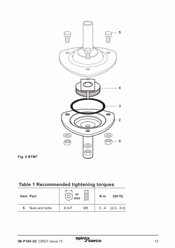
BTS7 and BTS7.1 are sealed non-maintainable units. Note: Before actioning any maintenance programme observe the 'Safety information' in Section 1. 6.1 General information Before undertaking any maintenance on the trap it must be isolated from the supply line and return line and any pressure allowed to safely normalise to atmosphere. The trap should then be allowed to cool. When reassembling, ensure that all joint faces are clean. Always ensure the correct tools, safety procedures and protective equipment are used at all times. 6.2 How to fit new internals (BTM7 only):
- Remove nuts and bolts (5).
- The end connection (4) with internal seat, 'O' ring (3) and element assembly (2) can then be removed for cleaning or replacement. Ensure that the element assembly (2) on reassembly is fitted in the correct position (see Figure 6).
- Reassemble using a new 'O' ring (3) and with the valve head in position to close onto the seat orifice.
- Replace nuts and bolts (5) and tighten them to the recommended torque (see Table 1) and put back into service.
- Open isolation valves slowly until normal operating conditions are achieved.
- Check for leaks.
6. Maintenance
The operating element is a capsule containing a small quantity of a special liquid with a boiling point below that of water. In the cold conditions that exist at start-up, the capsule is relaxed. The valve is off its seat and is wide open, allowing unrestricted removal of air. This is a feature of all balanced pressure traps and explains why they are well suited to air venting.As condensate passes through the balanced pressure steam trap, heat is transferred to the liquid in the capsule. The fill liquid boils before steam reaches the trap. The vapour pressure within the capsule causes it to expand and the trap shuts. Heat loss from the trap then cools the water surrounding the capsule, the fill condenses and the capsule contracts, opening the valve and releasing condensate until steam temperature approaches again at which the cycle is repeated.If the capsule is subjected to superheated steam it may cause it to over expand. This will prevent correct operation.
5. Operation
IM-P180-05 CMGT Issue 13 13
Fig. 6 BTM7
Table 1 Recommended tightening torques
Item Part ormm N m (lbf ft)
5 Nuts and bolts 8 A/F M5 3 - 4 (2.5 - 3.0)
5
4
3
2
5

IM-P180-05 CMGT Issue 1314
BTM7 only - Available spares are shown in solid outline. Parts drawn in a grey line are not available as spares.
Available sparesElement assembly 2
'O' ring (packet of 3) 3
Body with seat (outlet) 4
How to order sparesAlways order spares by using the description given in the column headed 'Available spares' and state the size, type and end connection of the trap.
Example: 1 - Body with seat (outlet) for a Spirax Sarco ½" BTM7 stainless steel thermostatic steam trap having screwed NPT connections.
7. Spare parts
Fig. 7 BTM7
5
4
3
2
5

IM-P180-05 CMGT Issue 13 15

IM-P180-05 CMGT Issue 1316