b.tech (eee) 2012(modified) & 2013 - christ university
TRANSCRIPT
FACULTY OF ENGINEERING
Kengeri Campus, Kanminike, Kumbalagodu, Bangalore – 560060
B.TECH (EEE)
2012(MODIFIED) & 2013
Christ University Faculty of Engineering Department of Electrical & Electronics Engineering
B.Tech (EEE) 2012 ( MODIFIED) & 2013 Page 1
TABLE OF CONTENTS
S.NO
DESCRIPTION PAGE
NUMBER
1 INTRODUCTION
2
2 COURSES OFFERED
5
3 ELIGIBILITY CRITERIA
6
4 SELECTION PROCESS
7
5 ADMISSION PROCESS
8
6 GENERAL RULES
9
7 GRADING SCHEME FOR EACH PAPER:
UNDERGRADUATE COURSES
10
8 GRADING SCHEME FOR EACH PAPER:
POSTGRADUATE COURSES
11
9 COURSE OVERVIEW
12
10 COURSE OBJECTIVE
13
11 TEACHING PEDAGOGY
14
12 ASSESSMENT RULES
15
13 QUESTION PAPER PATTERN
16
14 BRIEF OF PHYSICS AND CHEMISTRY CYCLE
18
15 COURSE STRUCTURE
19
16 DETAILED SYLLABUS
30
1.
Christ University Faculty of Engineering Department of Electrical & Electronics Engineering
B.Tech (EEE) 2012 ( MODIFIED) & 2013 Page 2
1. INTRODUCTION
Christ University was formerly Christ College (Autonomous) affiliated to
Bangalore University. Established in July 1969, Christ College became the most
preferred educational institution in the city of Bangalore within the first three decades.
From 1990 onwards it scaled from heights to heights. By the introduction of innovative
and modern curriculum, insistence on academic discipline, imparting of Holistic
Education and with the help of the creative and dedicated staff, Christ College has been
continually rated among the top 10 educational institutions of the country. It has the rare
distinction to be the first institution in Karnataka to be accredited by National Assessment
and Accreditation Council (NAAC) UGC for quality education. On 7 October 2004,
UGC has conferred Autonomy to Christ College (No.F.13-1/2004).
On May 20, 2005, it became the first College in South India to be reaccredited with A+
by NAAC. UGC has identified it as an Institution with Potential for Excellence in June
2006.
July 22, 2008 is the most glorious day in the history of the institution. Under Section 3 of
the UGC Act, 1956, Ministry of Human Resources Development of the Union
Government of India, vide Notification No. F. 9-34/2007-U.3 (A), has declared it a
Deemed to be University, in the name and style of Christ University
Christ University Faculty of Engineering Department of Electrical & Electronics Engineering
B.Tech (EEE) 2012 ( MODIFIED) & 2013 Page 3
VISION
"EXCELLENCE AND SERVICE"
Christ University, a premier educational institution, is an academic fraternity of
individuals dedicated to the motto of excellence and service. We strive to reach out
to the star of perfection through an earnest academic pursuit for excellence and our
efforts blossom into ‘service’ through our creative and empathetic involvement in the
society to transform it.
Education prepares one to face the challenges of life by bringing out the best in
him/her. If this is well accepted, education should be relevant to the needs of the time
and address the problems of the day. Being inspired by Blessed Kuriakose Elias
Chavara, the founder of Carmelites of Mary Immaculate and the pioneer in
innovative education, Christ University was proactive to define and redefine its
mission and strategies reading the signs of the time.
MISSION STATEMENT
"Christ University is a nurturing ground for an individuals holistic development to make
effective contribution to the society in a dynamic environment."
CORE VALUES
The values which guide us at Christ University are:
Faith in God
Moral Uprightness
Love of Fellow Beings
Social Responsibility
Pursuit of Excellence
Christ University Faculty of Engineering Department of Electrical & Electronics Engineering
B.Tech (EEE) 2012 ( MODIFIED) & 2013 Page 4
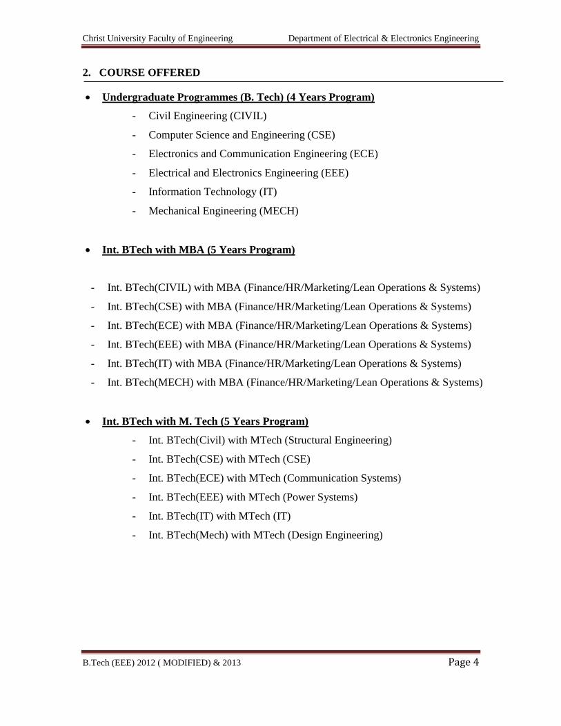
2. COURSE OFFERED
Undergraduate Programmes (B. Tech) (4 Years Program)
- Civil Engineering (CIVIL)
- Computer Science and Engineering (CSE)
- Electronics and Communication Engineering (ECE)
- Electrical and Electronics Engineering (EEE)
- Information Technology (IT)
- Mechanical Engineering (MECH)
Int. BTech with MBA (5 Years Program)
- Int. BTech(CIVIL) with MBA (Finance/HR/Marketing/Lean Operations & Systems)
- Int. BTech(CSE) with MBA (Finance/HR/Marketing/Lean Operations & Systems)
- Int. BTech(ECE) with MBA (Finance/HR/Marketing/Lean Operations & Systems)
- Int. BTech(EEE) with MBA (Finance/HR/Marketing/Lean Operations & Systems)
- Int. BTech(IT) with MBA (Finance/HR/Marketing/Lean Operations & Systems)
- Int. BTech(MECH) with MBA (Finance/HR/Marketing/Lean Operations & Systems)
Int. BTech with M. Tech (5 Years Program)
- Int. BTech(Civil) with MTech (Structural Engineering)
- Int. BTech(CSE) with MTech (CSE)
- Int. BTech(ECE) with MTech (Communication Systems)
- Int. BTech(EEE) with MTech (Power Systems)
- Int. BTech(IT) with MTech (IT)
- Int. BTech(Mech) with MTech (Design Engineering)
Christ University Faculty of Engineering Department of Electrical & Electronics Engineering
B.Tech (EEE) 2012 ( MODIFIED) & 2013 Page 5
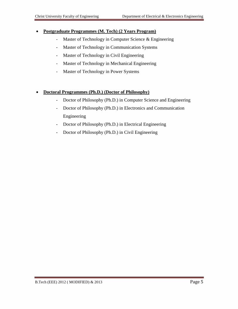
Postgraduate Programmes (M. Tech) (2 Years Program)
- Master of Technology in Computer Science & Engineering
- Master of Technology in Communication Systems
- Master of Technology in Civil Engineering
- Master of Technology in Mechanical Engineering
- Master of Technology in Power Systems
Doctoral Programmes (Ph.D.) (Doctor of Philosophy)
- Doctor of Philosophy (Ph.D.) in Computer Science and Engineering
- Doctor of Philosophy (Ph.D.) in Electronics and Communication
Engineering
- Doctor of Philosophy (Ph.D.) in Electrical Engineering
- Doctor of Philosophy (Ph.D.) in Civil Engineering
Christ University Faculty of Engineering Department of Electrical & Electronics Engineering
B.Tech (EEE) 2012 ( MODIFIED) & 2013 Page 6
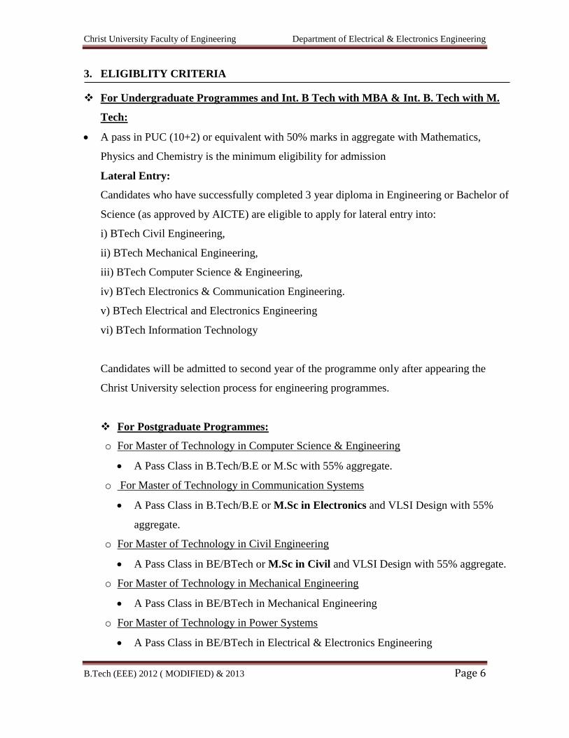
3. ELIGIBLITY CRITERIA
For Undergraduate Programmes and Int. B Tech with MBA & Int. B. Tech with M.
Tech:
A pass in PUC (10+2) or equivalent with 50% marks in aggregate with Mathematics,
Physics and Chemistry is the minimum eligibility for admission
Lateral Entry:
Candidates who have successfully completed 3 year diploma in Engineering or Bachelor of
Science (as approved by AICTE) are eligible to apply for lateral entry into:
i) BTech Civil Engineering,
ii) BTech Mechanical Engineering,
iii) BTech Computer Science & Engineering,
iv) BTech Electronics & Communication Engineering.
v) BTech Electrical and Electronics Engineering
vi) BTech Information Technology
Candidates will be admitted to second year of the programme only after appearing the
Christ University selection process for engineering programmes.
For Postgraduate Programmes:
o For Master of Technology in Computer Science & Engineering
A Pass Class in B.Tech/B.E or M.Sc with 55% aggregate.
o For Master of Technology in Communication Systems
A Pass Class in B.Tech/B.E or M.Sc in Electronics and VLSI Design with 55%
aggregate.
o For Master of Technology in Civil Engineering
A Pass Class in BE/BTech or M.Sc in Civil and VLSI Design with 55% aggregate.
o For Master of Technology in Mechanical Engineering
A Pass Class in BE/BTech in Mechanical Engineering
o For Master of Technology in Power Systems
A Pass Class in BE/BTech in Electrical & Electronics Engineering
Christ University Faculty of Engineering Department of Electrical & Electronics Engineering
B.Tech (EEE) 2012 ( MODIFIED) & 2013 Page 7
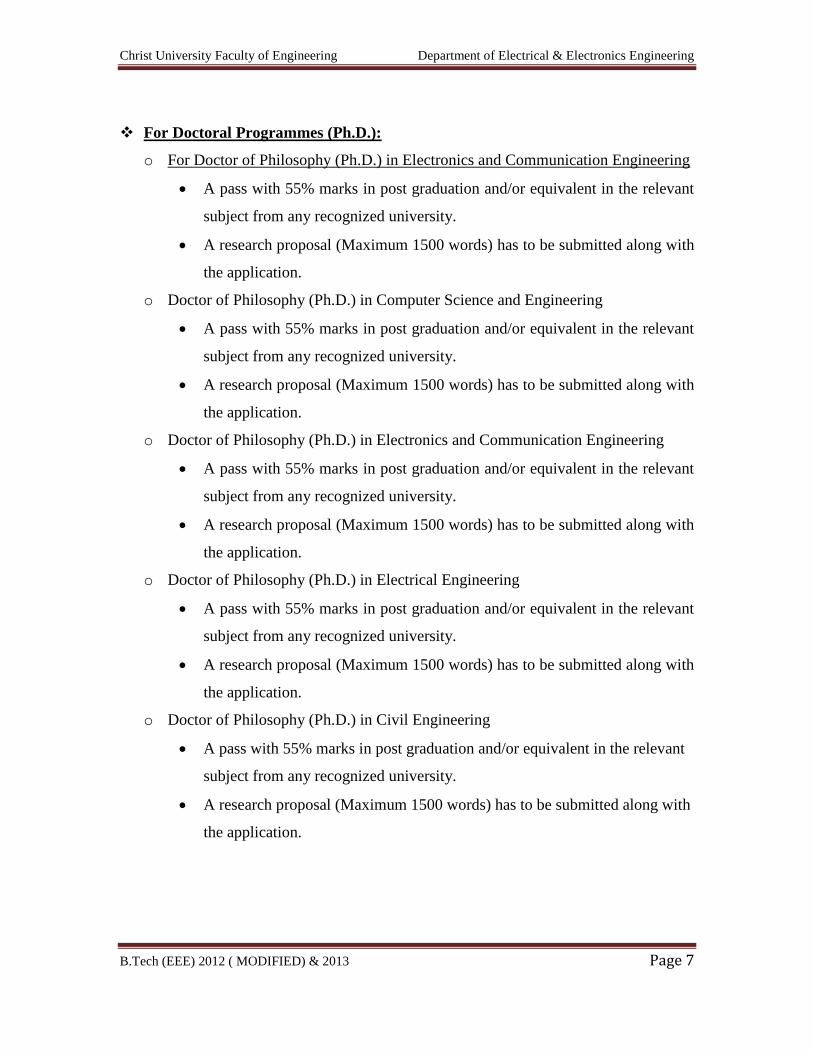
For Doctoral Programmes (Ph.D.):
o For Doctor of Philosophy (Ph.D.) in Electronics and Communication Engineering
A pass with 55% marks in post graduation and/or equivalent in the relevant
subject from any recognized university.
A research proposal (Maximum 1500 words) has to be submitted along with
the application.
o Doctor of Philosophy (Ph.D.) in Computer Science and Engineering
A pass with 55% marks in post graduation and/or equivalent in the relevant
subject from any recognized university.
A research proposal (Maximum 1500 words) has to be submitted along with
the application.
o Doctor of Philosophy (Ph.D.) in Electronics and Communication Engineering
A pass with 55% marks in post graduation and/or equivalent in the relevant
subject from any recognized university.
A research proposal (Maximum 1500 words) has to be submitted along with
the application.
o Doctor of Philosophy (Ph.D.) in Electrical Engineering
A pass with 55% marks in post graduation and/or equivalent in the relevant
subject from any recognized university.
A research proposal (Maximum 1500 words) has to be submitted along with
the application.
o Doctor of Philosophy (Ph.D.) in Civil Engineering
A pass with 55% marks in post graduation and/or equivalent in the relevant
subject from any recognized university.
A research proposal (Maximum 1500 words) has to be submitted along with
the application.
Christ University Faculty of Engineering Department of Electrical & Electronics Engineering
B.Tech (EEE) 2012 ( MODIFIED) & 2013 Page 8
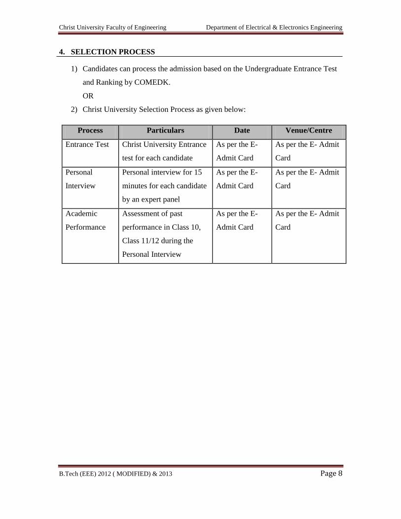
4. SELECTION PROCESS
1) Candidates can process the admission based on the Undergraduate Entrance Test
and Ranking by COMEDK.
OR
2) Christ University Selection Process as given below:
Process Particulars Date Venue/Centre
Entrance Test Christ University Entrance
test for each candidate
As per the E-
Admit Card
As per the E- Admit
Card
Personal
Interview
Personal interview for 15
minutes for each candidate
by an expert panel
As per the E-
Admit Card
As per the E- Admit
Card
Academic
Performance
Assessment of past
performance in Class 10,
Class 11/12 during the
Personal Interview
As per the E-
Admit Card
As per the E- Admit
Card
Christ University Faculty of Engineering Department of Electrical & Electronics Engineering
B.Tech (EEE) 2012 ( MODIFIED) & 2013 Page 9
5. ADMISSION PROCESS
Candidates will be intimated about the Selection status (Selected/Wait Listed/Not
Selected) through the University Notice Board/on the “Application Status” link on
University website. The Selection results will be declared within 24 hours of Personal
Interview session.
The selected candidates must process admission at Office of Admissions,
Central Block, Christ University within 3 working days of declaration of Selection
Process results/as per the stipulated date and time mentioned by Office of
Admissions.
Selected candidates should collect the Fee Challan from the Office of Admissions
and remit the Annual fee at the South Indian Bank, Christ University Branch. The Offer
of Admission will stand cancelled, if failing to remit the fee within the stipulated date
and time.
Admission will not be processed without the presence of the candidate and the
mandatory original documents mentioned below;
1. The Offer of Admission Card (E-Admission Card/Mail)
2. Class 10 Marks Statement
3. Class 11 Marks Statement, if Candidate is pursuing class 12 and appearing for
final examination during March-April 2012
4. Class 12 Marks Statement, if candidate has appeared and passed the Class 12
examination
The University ID card is a smart card, which is both an ID card as well as a
South Indian Bank ATM card with a chip containing the student personal details. All
transactions within the University campus after commencement of classes, including fees
payment will be processed only through this card. It is also an access card for Library and
other restricted places. Candidates are advised to collect the South Indian Bank account
opening form along with fees challan and process it at the Bank branch within the
University premises.
Christ University Faculty of Engineering Department of Electrical & Electronics Engineering
B.Tech (EEE) 2012 ( MODIFIED) & 2013 Page 10
Candidates who fall under International student category (ISC), If selected, should
register with the Foreigner Regional Registration Officer (FRRO/FRO) of the Local
Police in Bangalore, India within 14 working days from the date of admission or arriving
in Bangalore.
All International student category (ISC) candidates if studied in India should obtain an
NOC from the previous qualifying institution.
Christ University Faculty of Engineering Department of Electrical & Electronics Engineering
B.Tech (EEE) 2012 ( MODIFIED) & 2013 Page 11
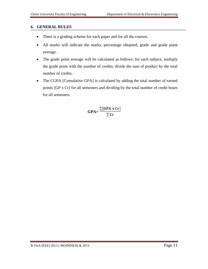
6. GENERAL RULES
There is a grading scheme for each paper and for all the courses.
All marks will indicate the marks, percentage obtained, grade and grade point
average.
The grade point average will be calculated as follows: for each subject, multiply
the grade point with the number of credits; divide the sum of product by the total
number of credits.
The CGPA [Cumulative GPA] is calculated by adding the total number of earned
points [GP x Cr] for all semesters and dividing by the total number of credit hours
for all semesters.
GPA=
Christ University Faculty of Engineering Department of Electrical & Electronics Engineering
B.Tech (EEE) 2012 ( MODIFIED) & 2013 Page 12
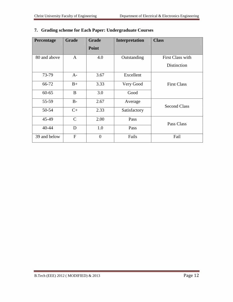
7. Grading scheme for Each Paper: Undergraduate Courses
Percentage Grade Grade
Point
Interpretation Class
80 and above A 4.0 Outstanding First Class with
Distinction
73-79 A- 3.67 Excellent
First Class 66-72 B+ 3.33 Very Good
60-65 B 3.0 Good
55-59 B- 2.67 Average Second Class
50-54 C+ 2.33 Satisfactory
45-49 C 2.00 Pass Pass Class
40-44 D 1.0 Pass
39 and below F 0 Fails Fail
Christ University Faculty of Engineering Department of Electrical & Electronics Engineering
B.Tech (EEE) 2012 ( MODIFIED) & 2013 Page 13
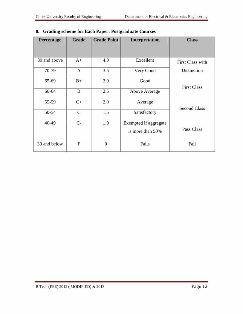
8. Grading scheme for Each Paper: Postgraduate Courses
Percentage Grade Grade Point Interpretation Class
80 and above A+ 4.0 Excellent First Class with
Distinction 70-79 A 3.5 Very Good
65-69 B+ 3.0 Good
First Class 60-64 B 2.5 Above Average
55-59 C+ 2.0 Average
Second Class 50-54 C 1.5 Satisfactory
40-49 C- 1.0 Exempted if aggregate
is more than 50% Pass Class
39 and below F 0 Fails Fail
Christ University Faculty of Engineering Department of Electrical & Electronics Engineering
B.Tech (EEE) 2012 ( MODIFIED) & 2013 Page 14
9. COURSE OVERVIEW:
Engineering Science is a key area in the study of an Engineering Course. A sound
knowledge of this area develops principles of physics, laws of Chemistry and
mathematical analytical skills, thus enabling graduates to solve numerical problems
encountered in daily life, particularly in the area of engineering.
An educational institution that does not respond to the present requirement and
changes and does not lead to research will remain on the way side of the higher education
missing the opportunities for going beyond. Keeping our vision “Excellence and
Service”, Engineering Science introduces student to those areas of Science which, from a
modern point of view, are most important in connection with practical problems.
Christ University Faculty of Engineering Department of Electrical & Electronics Engineering
B.Tech (EEE) 2012 ( MODIFIED) & 2013 Page 15
10. COURSE OBJECTIVE:
The B. Tech. course aims at to fulfill the following broad objectives:
1. To make aware students about the importance and symbiosis between Science and
Engineering.
2. Developing a respectable intellectual level seeking to expose the various concepts
in Science.
3. To enhance the students reasoning, analytical and problem solving skills.
4. To cultivate a scientific habit of thought and reasoning.
5. To develop a research culture in young minds.
6. Development of students’ competence by evolving a learner centered curriculum.
7. To encourage the students to uphold scientific integrity and objectivity in
professional endeavors.
8. To translate a given physical or other information and data into mathematical
form.
9. Obtaining the solution by selecting and applying suitable mathematical models.
During the course students will learn to balance between the development of
understanding and mastering of solution techniques with emphasis being on the
development of student’s ability to use Science and Mathematics with understanding to
solve Engineering problems by retaining the philosophy of “learning by doing”.
After the completion of this course prospective engineers will be able to apply the
concepts of Science, Mathematics and basic Engineering in their professional courses and
will be able to demonstrate effective problem solving methodology. The upcoming
engineers will become familiar with ways to think scientifically, mathematically and
technically, recognize the need for applying science and mathematics methods to
engineering problems and get a firm grasp for the interrelation between theory,
computing and experiment.
Christ University Faculty of Engineering Department of Electrical & Electronics Engineering
B.Tech (EEE) 2012 ( MODIFIED) & 2013 Page 16
11. TEACHING PEDAGOGY:
Our teaching methodology ensures that students are being exposed to a holistic education
experience in an active and dynamic learning environment, giving them the opportunity
to identify and realize their potential, and to achieve excellence. In order to realize the
objectives, a methodology based on the combination of the following will be adopted:
Team/Class room teaching.
PowerPoint presentations and handouts.
Simulated situations and role-plays.
Video films on actual situations.
Assignments.
Case Studies.
Exercises are solved hands on.
Seminars
Industry / Field visits.
Information and Communication Technology.
Project work.
Learning Management System.
Christ University Faculty of Engineering Department of Electrical & Electronics Engineering
B.Tech (EEE) 2012 ( MODIFIED) & 2013 Page 17
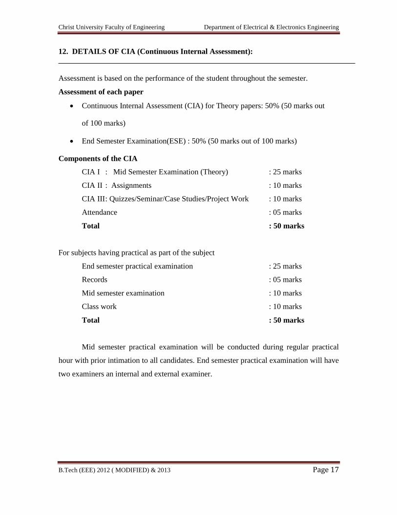
12. DETAILS OF CIA (Continuous Internal Assessment):
Assessment is based on the performance of the student throughout the semester.
Assessment of each paper
Continuous Internal Assessment (CIA) for Theory papers: 50% (50 marks out
of 100 marks)
End Semester Examination(ESE) : 50% (50 marks out of 100 marks)
Components of the CIA
CIA I : Mid Semester Examination (Theory) : 25 marks
CIA II : Assignments : 10 marks
CIA III : Quizzes/Seminar/Case Studies/Project Work : 10 marks
Attendance : 05 marks
Total : 50 marks
For subjects having practical as part of the subject
End semester practical examination : 25 marks
Records : 05 marks
Mid semester examination : 10 marks
Class work : 10 marks
Total : 50 marks
Mid semester practical examination will be conducted during regular practical
hour with prior intimation to all candidates. End semester practical examination will have
two examiners an internal and external examiner.
Christ University Faculty of Engineering Department of Electrical & Electronics Engineering
B.Tech (EEE) 2012 ( MODIFIED) & 2013 Page 18
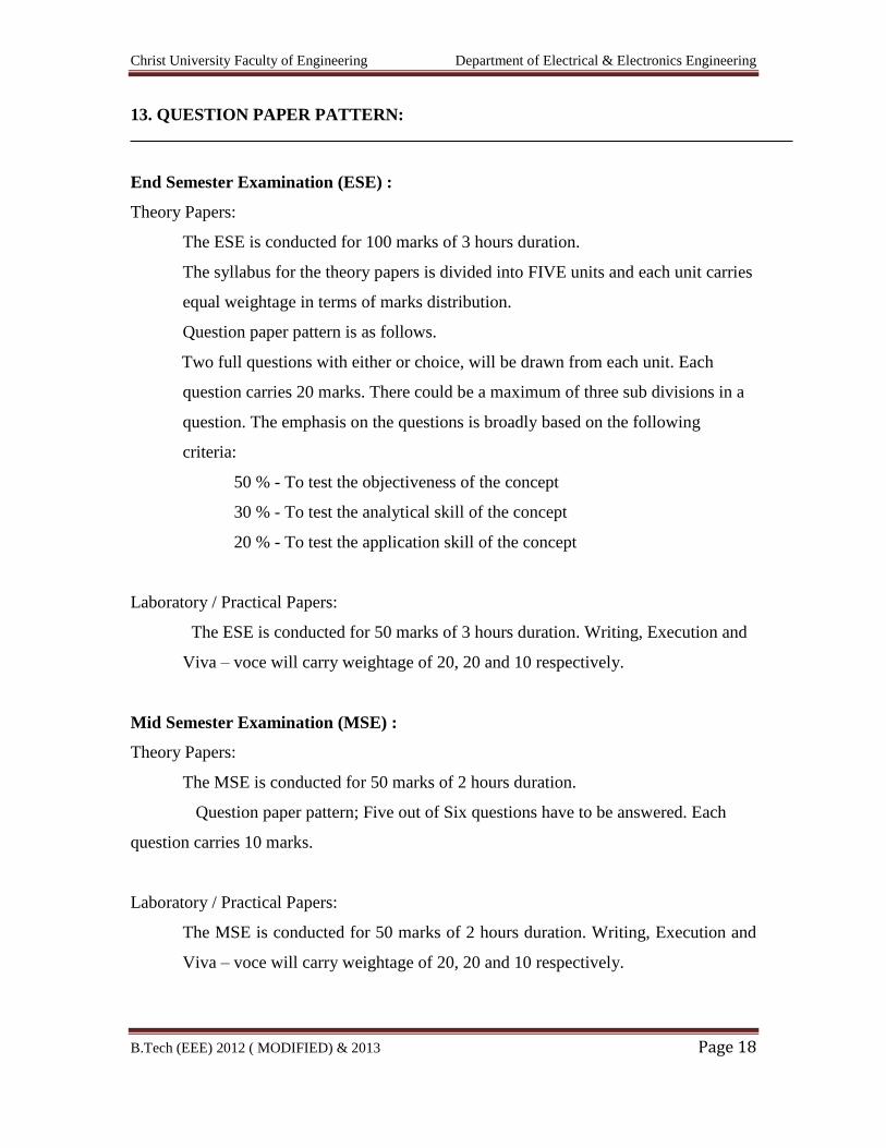
13. QUESTION PAPER PATTERN:
End Semester Examination (ESE) :
Theory Papers:
The ESE is conducted for 100 marks of 3 hours duration.
The syllabus for the theory papers is divided into FIVE units and each unit carries
equal weightage in terms of marks distribution.
Question paper pattern is as follows.
Two full questions with either or choice, will be drawn from each unit. Each
question carries 20 marks. There could be a maximum of three sub divisions in a
question. The emphasis on the questions is broadly based on the following
criteria:
50 % - To test the objectiveness of the concept
30 % - To test the analytical skill of the concept
20 % - To test the application skill of the concept
Laboratory / Practical Papers:
The ESE is conducted for 50 marks of 3 hours duration. Writing, Execution and
Viva – voce will carry weightage of 20, 20 and 10 respectively.
Mid Semester Examination (MSE) :
Theory Papers:
The MSE is conducted for 50 marks of 2 hours duration.
Question paper pattern; Five out of Six questions have to be answered. Each
question carries 10 marks.
Laboratory / Practical Papers:
The MSE is conducted for 50 marks of 2 hours duration. Writing, Execution and
Viva – voce will carry weightage of 20, 20 and 10 respectively.
Christ University Faculty of Engineering Department of Electrical & Electronics Engineering
B.Tech (EEE) 2012 ( MODIFIED) & 2013 Page 19
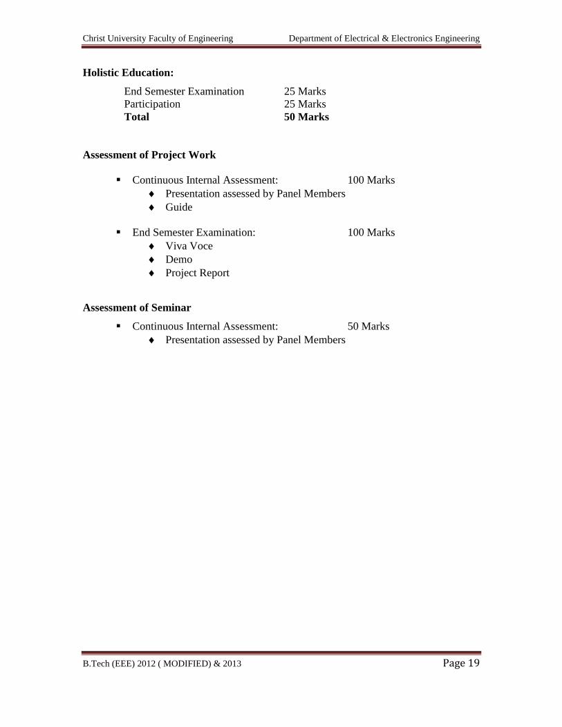
Holistic Education:
End Semester Examination 25 Marks
Participation 25 Marks
Total 50 Marks
Assessment of Project Work
Continuous Internal Assessment: 100 Marks
Presentation assessed by Panel Members
Guide
End Semester Examination: 100 Marks
Viva Voce
Demo
Project Report
Assessment of Seminar
Continuous Internal Assessment: 50 Marks
Presentation assessed by Panel Members
Christ University Faculty of Engineering Department of Electrical & Electronics Engineering
B.Tech (EEE) 2012 ( MODIFIED) & 2013 Page 20
14. BRIEF OF PHYSICS AND CHEMISTRY CYCLE:
All the student in B. Tech first year are divided into two groups i.e. Circuit and
Non-Circuit branches (i.e. Physics and Chemistry Cycle respectively)
The students in Physics Cycle and Chemistry Cycle being swapped between
Chemistry & Physics Cycle respectively in next Semester (i.e. Second semester).
Christ University Faculty of Engineering Department of Electrical & Electronics Engineering
B.Tech (EEE) 2012 ( MODIFIED) & 2013 Page 21
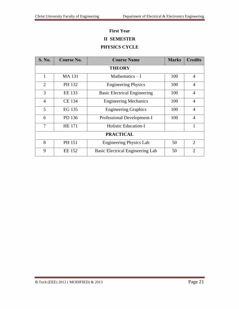
First Year
II SEMESTER
PHYSICS CYCLE
S. No. Course No. Course Name Marks Credits
THEORY
1 MA 131 Mathematics – I 100 4
2 PH 132 Engineering Physics 100 4
3 EE 133 Basic Electrical Engineering 100 4
4 CE 134 Engineering Mechanics 100 4
5 EG 135 Engineering Graphics 100 4
6 PD 136 Professional Development-I 100 4
7 HE 171 Holistic Education-I 1
PRACTICAL
8 PH 151 Engineering Physics Lab 50 2
9 EE 152 Basic Electrical Engineering Lab 50 2
Christ University Faculty of Engineering Department of Electrical & Electronics Engineering
B.Tech (EEE) 2012 ( MODIFIED) & 2013 Page 22
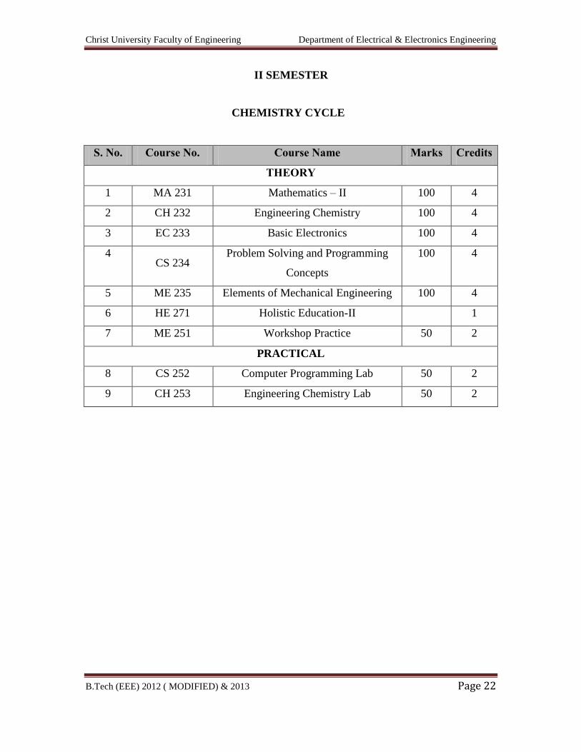
II SEMESTER
CHEMISTRY CYCLE
S. No. Course No. Course Name Marks Credits
THEORY
1 MA 231 Mathematics – II 100 4
2 CH 232 Engineering Chemistry 100 4
3 EC 233 Basic Electronics 100 4
4 CS 234
Problem Solving and Programming
Concepts
100 4
5 ME 235 Elements of Mechanical Engineering 100 4
6 HE 271 Holistic Education-II 1
7 ME 251 Workshop Practice 50 2
PRACTICAL
8 CS 252 Computer Programming Lab 50 2
9 CH 253 Engineering Chemistry Lab 50 2

Christ University Faculty of Engineering Department of Electrical & Electronics Engineering
B.Tech (EEE) 2012 ( MODIFIED) & 2013 Page 23
(SECOND YEAR)
SEMESTER III
Sl. No Course No Course Name Marks Credit
1 EE331 Mathematics - III 100 4
2 EE332 Electrical Machines – I 100 4
3 EE333 Electronic Devices and Electronic Circuits - I 100 4
4 EE334 Circuit Analysis 100 4
5 EE335 Electromagnetic Theory 100 4
6 EE336 Digital Logic Circuits 100 4
7 EE351 Electrical Machines Laboratory – I 50 2
8 EE352 Electric Circuits lab 50 2
9 HE371 Holistic Education 1
Christ University Faculty of Engineering Department of Electrical & Electronics Engineering
B.Tech (EEE) 2012 ( MODIFIED) & 2013 Page 24
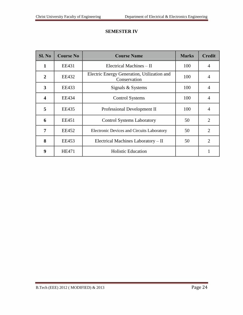
SEMESTER IV
Sl. No Course No Course Name Marks Credit
1 EE431 Electrical Machines – II 100 4
2 EE432 Electric Energy Generation, Utilization and
Conservation 100 4
3 EE433 Signals & Systems 100 4
4 EE434 Control Systems 100 4
5 EE435 Professional Development II 100 4
6 EE451 Control Systems Laboratory 50 2
7 EE452 Electronic Devices and Circuits Laboratory 50 2
8 EE453 Electrical Machines Laboratory – II 50 2
9 HE471 Holistic Education 1
Christ University Faculty of Engineering Department of Electrical & Electronics Engineering
B.Tech (EEE) 2012 ( MODIFIED) & 2013 Page 25
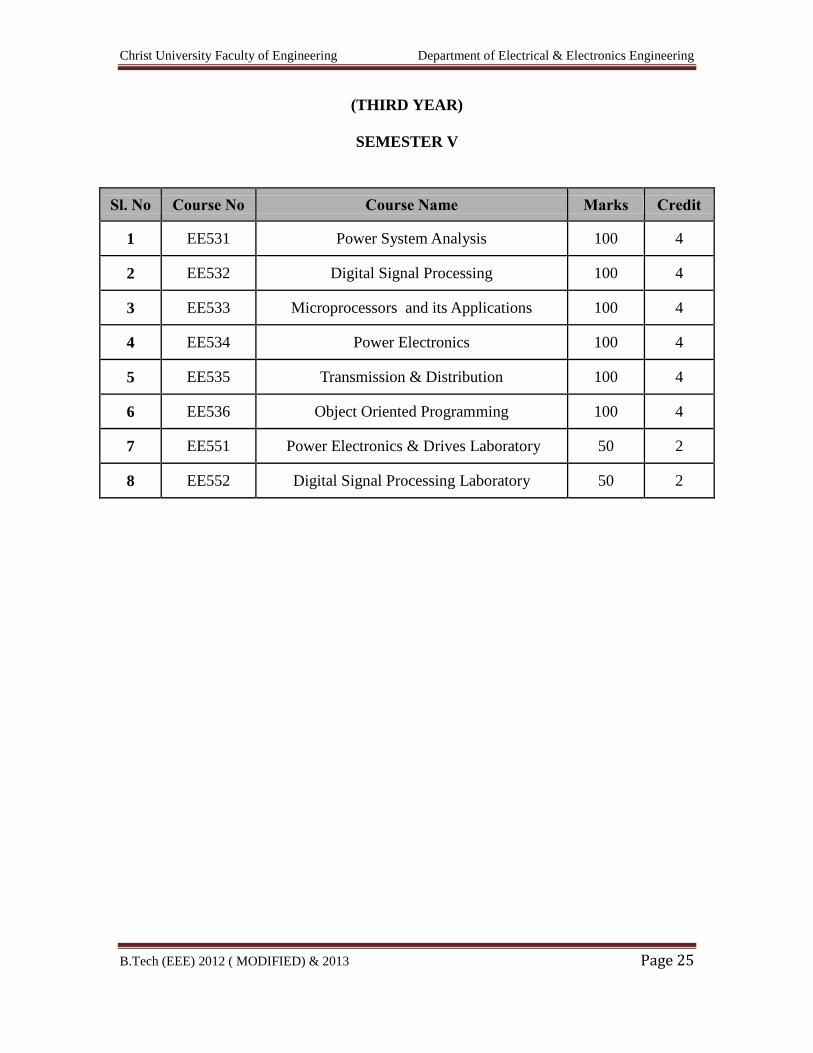
(THIRD YEAR)
SEMESTER V
Sl. No Course No Course Name Marks Credit
1 EE531 Power System Analysis 100 4
2 EE532 Digital Signal Processing 100 4
3 EE533 Microprocessors and its Applications 100 4
4 EE534 Power Electronics 100 4
5 EE535 Transmission & Distribution 100 4
6 EE536 Object Oriented Programming 100 4
7 EE551 Power Electronics & Drives Laboratory 50 2
8 EE552 Digital Signal Processing Laboratory 50 2
Christ University Faculty of Engineering Department of Electrical & Electronics Engineering
B.Tech (EEE) 2012 ( MODIFIED) & 2013 Page 26
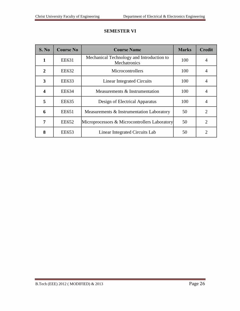
SEMESTER VI
S. No Course No Course Name Marks Credit
1 EE631 Mechanical Technology and Introduction to
Mechatronics 100 4
2 EE632 Microcontrollers 100 4
3 EE633 Linear Integrated Circuits 100 4
4 EE634 Measurements & Instrumentation 100 4
5 EE635 Design of Electrical Apparatus 100 4
6 EE651 Measurements & Instrumentation Laboratory 50 2
7 EE652 Microprocessors & Microcontrollers Laboratory 50 2
8 EE653 Linear Integrated Circuits Lab 50 2

Christ University Faculty of Engineering Department of Electrical & Electronics Engineering
B.Tech (EEE) 2012 ( MODIFIED) & 2013 Page 27
(FOURTH YEAR)
SEMESTER VII
Sl. No Course No Course Name Marks Credit
1 EE731 Advanced Power System Analysis 100 4
2 EE732 High Voltage Engineering 100 4
3 EE733 Protection & Switchgear 100 4
4 EE734 VLSI Design 100 4
5 EE735 Elective – I 100 4
6 EE736 Elective – II 100 4
7 EE751 Power System Simulation Laboratory 50 2
8 EE752 High Voltage Laboratory 50 2

Christ University Faculty of Engineering Department of Electrical & Electronics Engineering
B.Tech (EEE) 2012 ( MODIFIED) & 2013 Page 28
SEMESTER VIII
Sl. No Course. No Course Name Marks Credit
1 EE831 Discrete Control Systems 100 4
2 EE832 Elective – III 100 4
3 EE833 Elective – IV 100 4
4 EE871 Project Work 200 8
5 Seminar 50 2
LIST OF ELECTIVES
Christ University Faculty of Engineering Department of Electrical & Electronics Engineering
B.Tech (EEE) 2012 ( MODIFIED) & 2013 Page 29
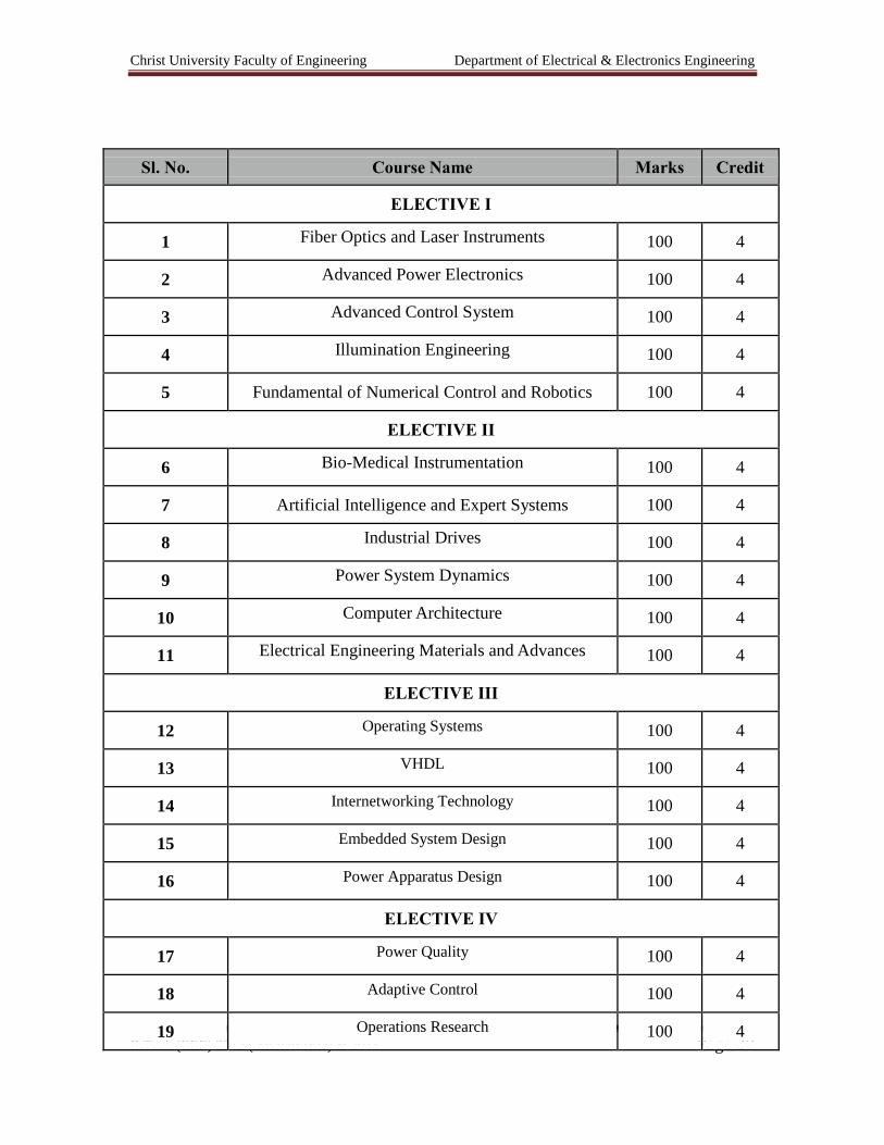
Sl. No. Course Name Marks Credit
ELECTIVE I
1 Fiber Optics and Laser Instruments 100 4
2 Advanced Power Electronics 100 4
3 Advanced Control System 100 4
4 Illumination Engineering 100 4
5 Fundamental of Numerical Control and Robotics 100 4
ELECTIVE II
6 Bio-Medical Instrumentation 100 4
7 Artificial Intelligence and Expert Systems 100 4
8 Industrial Drives 100 4
9 Power System Dynamics 100 4
10 Computer Architecture 100 4
11 Electrical Engineering Materials and Advances 100 4
ELECTIVE III
12 Operating Systems 100 4
13 VHDL 100 4
14 Internetworking Technology 100 4
15 Embedded System Design 100 4
16 Power Apparatus Design 100 4
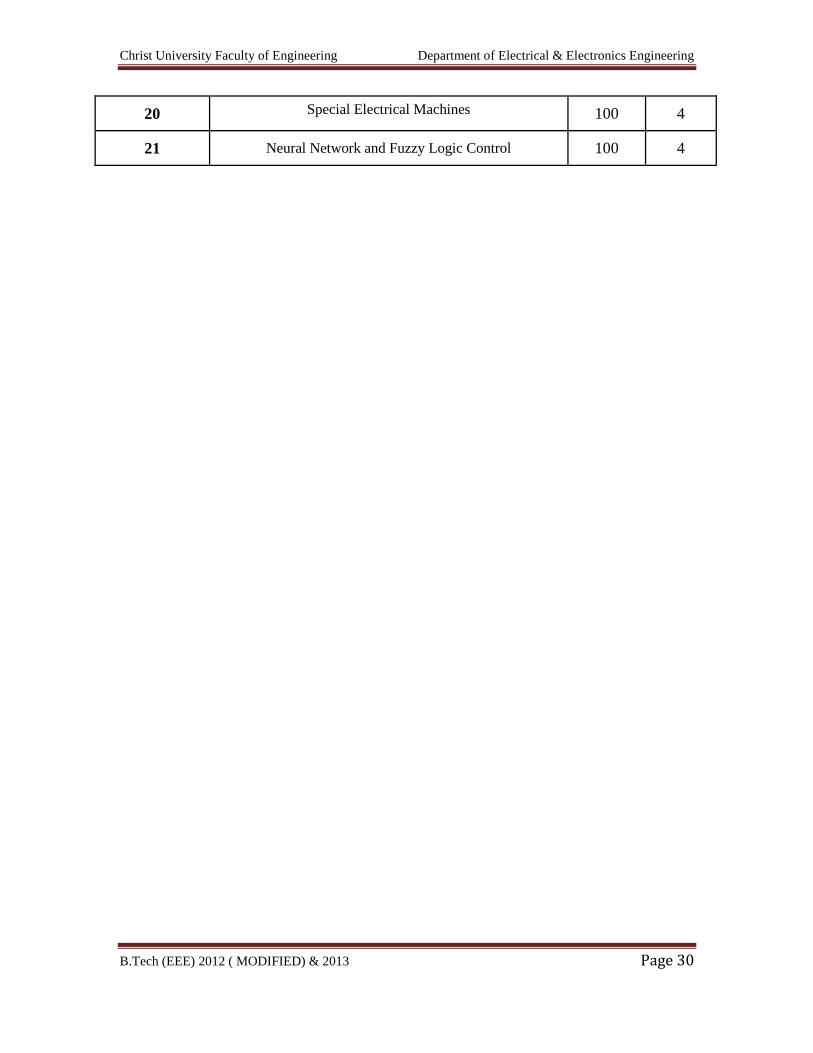
ELECTIVE IV
17 Power Quality 100 4
18 Adaptive Control 100 4
19 Operations Research 100 4
Christ University Faculty of Engineering Department of Electrical & Electronics Engineering
B.Tech (EEE) 2012 ( MODIFIED) & 2013 Page 30
20 Special Electrical Machines 100 4
21 Neural Network and Fuzzy Logic Control 100 4
Christ University Faculty of Engineering Department of Electrical & Electronics Engineering
B.Tech (EEE) 2012 ( MODIFIED) & 2013 Page 31
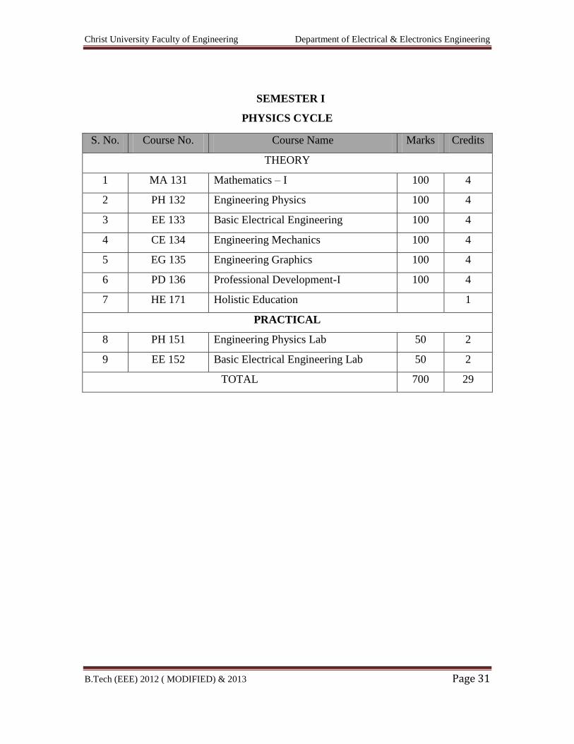
SEMESTER I
PHYSICS CYCLE
S. No. Course No. Course Name Marks Credits
THEORY
1 MA 131 Mathematics – I 100 4
2 PH 132 Engineering Physics 100 4
3 EE 133 Basic Electrical Engineering 100 4
4 CE 134 Engineering Mechanics 100 4
5 EG 135 Engineering Graphics 100 4
6 PD 136 Professional Development-I 100 4
7 HE 171 Holistic Education 1
PRACTICAL
8 PH 151 Engineering Physics Lab 50 2
9 EE 152 Basic Electrical Engineering Lab 50 2
TOTAL 700 29
Christ University Faculty of Engineering Department of Electrical & Electronics Engineering
B.Tech (EEE) 2012 ( MODIFIED) & 2013 Page 32
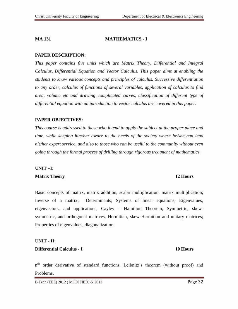
MA 131 MATHEMATICS - I
PAPER DESCRIPTION:
This paper contains five units which are Matrix Theory, Differential and Integral
Calculus, Differential Equation and Vector Calculus. This paper aims at enabling the
students to know various concepts and principles of calculus. Successive differentiation
to any order, calculus of functions of several variables, application of calculus to find
area, volume etc and drawing complicated curves, classification of different type of
differential equation with an introduction to vector calculus are covered in this paper.
PAPER OBJECTIVES:
This course is addressed to those who intend to apply the subject at the proper place and
time, while keeping him/her aware to the needs of the society where he/she can lend
his/her expert service, and also to those who can be useful to the community without even
going through the formal process of drilling through rigorous treatment of mathematics.
UNIT –I:
Matrix Theory 12 Hours
Basic concepts of matrix, matrix addition, scalar multiplication, matrix multiplication;
Inverse of a matrix; Determinants; Systems of linear equations, Eigenvalues,
eigenvectors, and applications, Cayley – Hamilton Theorem; Symmetric, skew-
symmetric, and orthogonal matrices, Hermitian, skew-Hermitian and unitary matrices;
Properties of eigenvalues, diagonalization
UNIT - II:
Differential Calculus - I 10 Hours
nth order derivative of standard functions. Leibnitz’s theorem (without proof) and
Problems.
Christ University Faculty of Engineering Department of Electrical & Electronics Engineering
B.Tech (EEE) 2012 ( MODIFIED) & 2013 Page 33
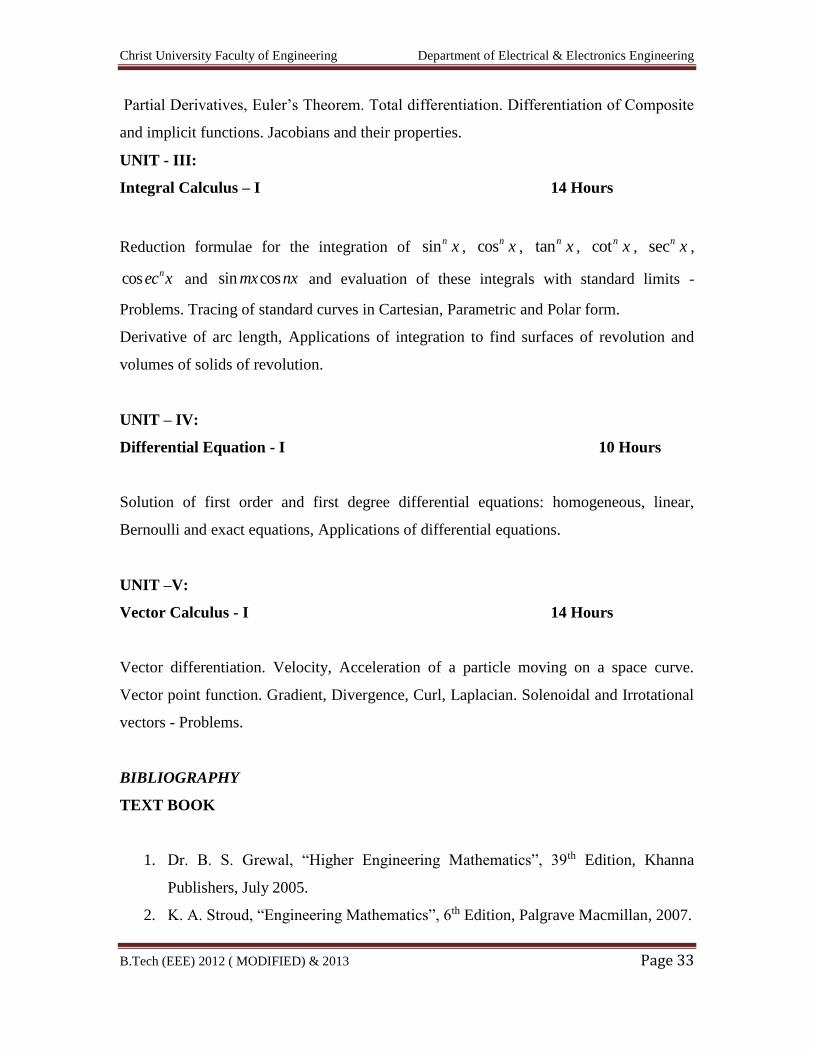
Partial Derivatives, Euler’s Theorem. Total differentiation. Differentiation of Composite
and implicit functions. Jacobians and their properties.
UNIT - III:
Integral Calculus – I 14 Hours
Reduction formulae for the integration of sinn x , cosn x , tann x , cotn x , secn x ,
cos nec x and sin cosmx nx and evaluation of these integrals with standard limits -
Problems. Tracing of standard curves in Cartesian, Parametric and Polar form.
Derivative of arc length, Applications of integration to find surfaces of revolution and
volumes of solids of revolution.
UNIT – IV:
Differential Equation - I 10 Hours
Solution of first order and first degree differential equations: homogeneous, linear,
Bernoulli and exact equations, Applications of differential equations.
UNIT –V:
Vector Calculus - I 14 Hours
Vector differentiation. Velocity, Acceleration of a particle moving on a space curve.
Vector point function. Gradient, Divergence, Curl, Laplacian. Solenoidal and Irrotational
vectors - Problems.
BIBLIOGRAPHY
TEXT BOOK
1. Dr. B. S. Grewal, “Higher Engineering Mathematics”, 39th Edition, Khanna
Publishers, July 2005.
2. K. A. Stroud, “Engineering Mathematics”, 6th Edition, Palgrave Macmillan, 2007.
Christ University Faculty of Engineering Department of Electrical & Electronics Engineering
B.Tech (EEE) 2012 ( MODIFIED) & 2013 Page 34
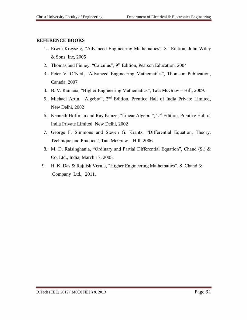
REFERENCE BOOKS
1. Erwin Kreyszig, “Advanced Engineering Mathematics”, 8th Edition, John Wiley
& Sons, Inc, 2005
2. Thomas and Finney, “Calculus”, 9th Edition, Pearson Education, 2004
3. Peter V. O’Neil, “Advanced Engineering Mathematics”, Thomson Publication,
Canada, 2007
4. B. V. Ramana, “Higher Engineering Mathematics”, Tata McGraw – Hill, 2009.
5. Michael Artin, “Algebra”, 2nd Edition, Prentice Hall of India Private Limited,
New Delhi, 2002
6. Kenneth Hoffman and Ray Kunze, “Linear Algebra”, 2nd Edition, Prentice Hall of
India Private Limited, New Delhi, 2002
7. George F. Simmons and Steven G. Krantz, “Differential Equation, Theory,
Technique and Practice”, Tata McGraw – Hill, 2006.
8. M. D. Raisinghania, “Ordinary and Partial Differential Equation”, Chand (S.) &
Co. Ltd., India, March 17, 2005.
9. H. K. Das & Rajnish Verma, “Higher Engineering Mathematics”, S. Chand &
Company Ltd., 2011.
Christ University Faculty of Engineering Department of Electrical & Electronics Engineering
B.Tech (EEE) 2012 ( MODIFIED) & 2013 Page 35
PH 132 ENGINEERING PHYSICS
(Common for all branches)
PAPER DESCRIPTION:
This paper contains five UNITs which are
Modern Physics and Quantum Mechanics
Conductivity in Metals( Electrical and thermal)
Elastic, Dielectric, Magnetic and Optical Properties of Materials
Lasers, Optical Fibers and Ultrasonics
Crystal Structure and Modern Engineering materials.
This paper aims at enabling the students to know fundamentals covered in this paper.
PAPER OBJECTIVES:
To impart the basic concepts and ideas in physics.
To develop scientific attitudes and enable the students to correlate the concepts of
physics with the core programmes.
LEVEL OF KNOWLEDGE: Basic/working
UNIT – I 14
Hours
Modern Physics
Introduction to Blackbody radiation spectrum - Planck’s theory(qualitative) – Deduction
of Wien’s displacement law and Rayleigh Jean’s law from Planck’s theory – Quantum
theory applied to Einstein’s Photo-electric effect - Photo Multiplier Tube -Compton
effect - Wave particle Dualism -de Broglie hypothesis – de Broglie wavelength -
extension to electron particle – Davisson and Germer Experiment - Matter waves and
their Characteristic properties. Phase velocity, group velocity and Particle velocity.
(qualitative).Elementary particles – QUARKS – Types – Properties.
Quantum Mechanics
Heisenberg’s uncertainty principle and its physical significance(no derivation).
Application of uncertainty principle (Non-existence of electron in the nucleus).
Wave function. Properties and Physical significance of a wave function Schroedinger’s -
Time independent wave equation – Application: Setting up of a one dimensional
Christ University Faculty of Engineering Department of Electrical & Electronics Engineering
B.Tech (EEE) 2012 ( MODIFIED) & 2013 Page 36
Schrödinger wave equation of a particle in a potential well of infinite depth : Probability
density and Normalisation of wave function – Energy eigen values and eigen function.
UNIT – II 11 Hours
Conductivity in metals – Electrical and Thermal
Classical free-electron theory. Assumptions. Drift velocity. Mean collision time and
mean free path. Relaxation time. Expression for drift velocity. Expression for electrical
conductivity in metals. Effect of impurity and temperature on electrical resistivity of
metals. Failure of classical free-electron theory. Thermal Conductivity. Wiedmann-Franz
Law( relation between thermal conductivity & electrical conductivity).
Quantum free-electron theory - Assumptions. Fermi - Dirac Statistics. Fermi-energy –
Fermi factor. Density of states (with derivation). Carrier concentration in metals.
Expression for electrical resistivity/conductivity Temperature dependence of resistivity of
metals. Merits of Quantum free – electron theory.
UNIT – III 12 Hours
Properties of Materials
Elasticity: Elasticity – types of moduli of elasticity – stress strain diagram – Young’s
modulus of elasticity – rigidity modulus – bulk modulus – Poisson’s ratio –Bending of
beams – Single Cantilever - Young’s modulus-Non uniform bending.
Dielectric: Dielectric constant and polarisation of dielectric materials. Types of
polarisation. Equation for internal fields in liquids and solids (one dimensional). Clausius
– Mossotti equation. Ferro and Piezo – electricity(qualitative). Frequency dependence of
dielectric constant. Important applications of dielectric materials.
Optics : Phenomenon of diffusion, absorption and scattering of a light – Snell’s Law -
Interference – thin films - Air wedge theory and experiment Testing of flat surfaces. Anti
reflection coating single and multi layer.
UNIT – IV 12 Hours
Lasers : Principle and production. Einstein’s coefficients (expression for energy density).
Requisites of a Laser system. Condition for Laser action. Principle, Construction and
Christ University Faculty of Engineering Department of Electrical & Electronics Engineering
B.Tech (EEE) 2012 ( MODIFIED) & 2013 Page 37
working of Nd YAG and semiconductor diode Laser. Applications of Laser – Laser
welding, cutting and drilling. Measurement of atmospheric pollutants.
Optical Fibers : Principle and Propagation of light in optical fibers. Angle of acceptance.
Numerical aperture. Types of optical fibers and modes of propagation. Applications –
block diagram discussion of point to point communication.
Ultrasonics : Ultrasonics production – Magnetostriction and Piezoelectric methods –
Application (NDT) non-destructive testing of materials- Flaw detection- Measurement of
velocity in liquids. Determination of elastic constants in liquids using Ultrasonic
Interferometer.
UNIT - V
Material Science 12 Hours
Crystal Structure : Space lattice, Bravais lattice - UNIT cell, primitive cell. Lattice
parameters. Crystal systems. Direction and planes in a crystal. Miller indices. Expression
for inter-planar spacing. Co-ordination number. Atomic packing factor. Bragg’s Law.
Determination of crystal structure by Bragg’s x-ray spectrometer. Crystal structure of Na
Cl.
Modern Engineering Materials:
Metallic Glasses: Properties – Applications.
Shape Memory Alloys : Characteristics - Applications.
Cryogenics : Properties – Applications.
Nano-materials : Molecular Manufacturing. Fabrication technology. Scaling of classical
mechanical systems – Basic assumptions. Mechanical scaling. Carbon nano-tubes.
TEXT BOOKS:
1. M.N.Avadhanulu and P.G. Kshirsagar, “A Text Book of Engineering Physics”,
S.Chand & Company Ltd, 9th Edition 2012.
2. S.O. Pillai, “Solid State Physics”, New Age International, 6th Edition 2009.
3. S.P. Basavaraju, “ Engineering Physics”, Revised Edition 2009.
Christ University Faculty of Engineering Department of Electrical & Electronics Engineering
B.Tech (EEE) 2012 ( MODIFIED) & 2013 Page 38
REFERENCE BOOKS:
1. R.K. Gaur and S.L. Gupta, "Engineering Physics", Dhanpatrai and Sons,
New Delhi, 2001.
2. Sehgal Chopra Sehgal, “ Modern Physics ", Tata McGraw-Hill,
6th Edition, 2005.
3. Halliday, Resnick and Krane, "Fundamentals of Physics Extended",
John Wiley and Sons Inc., New York, 5th Edition, 1997.
4. P.Mani, “Engineering Physics”, Dhanam publishers, Revised Edition 2011.
5. H.J. Sawant, "Engineering Physics", Technical Publications, 1st Edition, 2010.
6. V. Rajendran, “Engineering Physics”, Tata Mcgraw Hill Publishing Company
Limited, 1st Edition, 2009.
7. K.Eric Drexler, “Nanosystems - Molecular Machinery, Manufacturing and
Computation”, John Wiely & Sons, 2005.
8. J David, N Cheeke , “Fundamentals and Applications of Ultrasonic Waves”, CRC
Press 1st Edition, 2002.
9. Frederick J Bueche and Eugene Hecht “Schaum Outline of Theory and Problems of
College Physics”, Tata McGraw-Hill, 11th Edition, 2012.
Christ University Faculty of Engineering Department of Electrical & Electronics Engineering
B.Tech (EEE) 2012 ( MODIFIED) & 2013 Page 39
EE 133 BASIC ELECTRICAL ENGINEERING
(Common for all branches)
PAPER DESCRIPTION:
This paper contains five units which are Analysis of DC circuits, Single phase & three
phase A C circuits, DC and AC machines and transformers. This paper aims at enabling
the students to provide comprehensive idea about circuit analysis, working principles of
machines covered in this paper.
PAPER OBJECTIVES:
At the end of the course students will be able
To understand the basic concepts of magnetic circuits, AC & DC circuits.
To solve the electrical network using mesh and nodal analysis
To understand the concept of active, reactive and apparent powers, power factor
and resonance in series and parallel circuits.
To know the basic concepts of three phase loads and power measurement.
To explain the working principle, construction, applications of DC & AC
machines
UNIT – I 12 Hours
Introduction to electrical power generation and distribution
ELECTRIC CIRCUIT ELEMENTS:
Sources: Ideal voltage source, practical voltage source, ideal current source, practical
current source, source transformation, Controlled sources.
Resistor: Resistance, linear and non-linear resistors, resistors in series, resistors in
parallel, current division, power consumed by a resistor.
Christ University Faculty of Engineering Department of Electrical & Electronics Engineering
B.Tech (EEE) 2012 ( MODIFIED) & 2013 Page 40
Capacitor: Capacitance, equivalent capacitance of capacitors in series, voltage division,
capacitors in parallel, energy stored by a capacitor.
Inductor: Inductance, self-induced emf, energy stored by an inductor, inductors in series,
inductors in parallel mutual Inductance, Co-efficient of coupling.
Resistive networks: star- delta and delta – star transformations, network reduction
technique.
UNIT – II 12 Hours
SINGLE-PHASE AC CIRCUITS:
Alternating voltages and currents, generation of single phase alternating voltage, average
value and rms value of periodic sinusoidal and non- sinusoidal wave forms, form factor.
Representation of time-varying quantities as phasors; the operator j; Representation of
complex quantities; Addition, subtraction, multiplication and division of phasors.
Basic ac circuits, sinusoidal alternating current in a pure resistor, pure inductor and a pure
capacitor, waveforms of voltage, current, and power, phasor diagram, inductive and
capacitive reactances.
RL, RC, and RLC circuits, concept of impedance and phasor diagram, expression for
average power, power factor, parallel ac circuits, conductance, susceptance and
admittance, analysis of series parallel circuits and phasor diagrams, active power, reactive
power, and apparent power, complex power and power triangle.
UNIT III 12 Hours
THREE-PHASE AC CIRCUITS:
Generation of 3-phase balanced sinusoidal voltages, waveform of 3-phase voltages, star
and delta connections, line voltage and phase voltage, line current and phase current,
analysis of 3-phase circuit with balanced supply voltage and with star/delta connected
balanced loads, measurement of active power using two-wattmeter method with balanced
loads.
Christ University Faculty of Engineering Department of Electrical & Electronics Engineering
B.Tech (EEE) 2012 ( MODIFIED) & 2013 Page 41
UNIT – IV 12 Hours
ELECTROMAGNETISM:
Introduction to electromagnetism, comparison of electrical circuit with magnetic circuit,
Magnetic flux, Flux density, Fleming's left hand rule, Faraday’s laws, Fleming's right
hand rule, Lenz’s law,
DC MACHINES:
Working principle of DC machine as a generator and motor. Constructional features.
E.M.F. equation of generator and illustrative examples. Back E.M.F. and torque
equations of D.C. motors. Types of D.C. motors.
UNIT – V 12 Hours
TRANSFORMERS: Types, constructional features, principle of operation, equation for
induced emf, transformation ratio, ideal transformer, transformer under no-load, losses,
efficiency, applications.
THREE-PHASE INDUCTION MOTORS:
Types, constructional details, production of rotating magnetic field, synchronous speed,
principle operation, slip, Necessity of a starter for 3-phase induction motor, Star –Delta
starter.
BIBILOGRAPH
TEXT BOOKS:
1. Arthur Eugene Fitzgerald, David E. Higginbotham, Arvin Grabel, “Basic electrical
engineering: circuits, electronics, machines, controls”, McGraw-Hill, Fifth Edition.
2. E. Hughes; “Electrical Technology", 9th Edition”, Pearson, 2005.
Christ University Faculty of Engineering Department of Electrical & Electronics Engineering
B.Tech (EEE) 2012 ( MODIFIED) & 2013 Page 42
REFERENCE BOOKS:
1. Kothari D. P. & Nagarath I. J, “Basic Electrical Technology”, TMH, 2004
2. Rajendra Prasad, “Fundamentals of Electrical Engineering”, Prentice Hall of India Pvt
Ltd., 2005
3. K.A. Krishnamurthy and M.R Raghuveer, “Electrical, Electronics and Computer
Engineering”, 2nd Edition, T.M.H., 2001
4. D C Kulshreshtha, “Basic Electrical Engineering”, TMH.
5. Abhijit Chakrabarti, Sudipta Nath & Chandan Kumar Chanda, “Basic Electrical
Engineering”, TMH, 2009.
Christ University Faculty of Engineering Department of Electrical & Electronics Engineering
B.Tech (EEE) 2012 ( MODIFIED) & 2013 Page 43
CE 134 ENGINEERING MECHANICS
(Common for all branches)
SUBJECT DESCRIPTION: This paper aims at enabling the students to know the
fundamentals Engineering Mechanics covered in this paper. This paper contains five
units which are Engineering Mechanics and its classification, Composition of Forces,
Equilibrium of Forces, Types of Supports, Analysis of trusses, Centriod and Moment of
Inertia and Friction.
SUBJECT OBJECTIVES:
The students will understand the basics of Engineering Mechanics
The students will understand the basic principles, laws, measurements,
calculations and SI units.
The students will understand mechanics that studies the effects of forces and
moments acting on rigid bodies that are either at rest or moving with constant
velocity along a straight path for static condition only.
The students will understand the basic concepts of forces in the member, centriod,
moment of inertia & friction
LEVEL OF KNOWLEDGE: Basic
UNIT – I: (15 HOURS)
INTRODUCTION TO ENGINEERING MECHANICS
Basic idealizations – Practical, Continuum, Rigid body and Point force; Newton’s laws of
motion, Definition of force, Introduction to SI units, Elements of a force, classification
of force and force systems; Principle of physical independence of forces, Principle of
superposition of forces, Principle of transmissibility of forces; Moment of a couple,
characteristics of couple, Equivalent force – couple system; Resolution of forces,
Christ University Faculty of Engineering Department of Electrical & Electronics Engineering
B.Tech (EEE) 2012 ( MODIFIED) & 2013 Page 44
composition of forces; Numerical problems on moment of forces and couples, on
equivalent force – couple system.
COMPOSITION OF FORCES: Definition of Resultant; Composition of coplanar –
concurrent force system, Principle of resolved parts; Numerical problems on composition
of coplanar concurrent force systems
COMPOSITION OF COPLANAR: Non-concurrent force system, Varignon’s principle
of moments; Numerical problems on composition of coplanar non-concurrent force
systems.
UNIT – II: (13 HOURS)
EQUILIBRIUM OF FORCES
Definition of Equilibrant; Conditions of static equilibrium for different force systems,
Lami’s theorem; Numerical problems on equilibrium of coplanar – concurrent force
system.
TYPES OF SUPPORTS: Statically determinate beams, Numerical problems on
equilibrium of coplanar-non- concurrent force system and support reactions for statically
determinate beams
UNIT – III: (09 HOURS)
ANALYSIS OF PLANE TRUSSES
Introduction to Determinate and Indeterminate plane trusses - Analysis of simply
supported and cantilevered trusses by method of joints and method of sections
UNIT – IV: (15 HOURS)
CENTROID OF PLANE FIGURES
Locating the centroid of triangle, semicircle, quadrant of a circle and sector of a circle
using method of integration, centroid of simple built up sections; Numerical problems.
Christ University Faculty of Engineering Department of Electrical & Electronics Engineering
B.Tech (EEE) 2012 ( MODIFIED) & 2013 Page 45
MOMENT OF INERTIA OF AN AREA: polar moment of inertia, Radius of gyration,
Perpendicular axis theorem and Parallel axis theorem; Moment of Inertia of rectangular,
circular and triangular areas from method of integration; Moment of inertia of composite
areas; Numerical problems.
UNIT – V: (08 HOURS)
FRICTION:
Types of friction, Laws of static friction, Limiting friction, Angle of friction, angle of
repose; Impending motion on horizontal and inclined planes; Wedge friction; Ladder
friction; Numerical problems.
TEXT BOOKS:
1. Bhavikatti S.S. “Elements of Civil Engineering (IV Edition) and Engineering
Mechanics”, 2/E, Vikas Publishing House Pvt. Ltd., New Delhi, 2008
2. Jagadeesh T.R. and Jay Ram, “Elements of Civil Engineering and Engineering
Mechanics”, 2/E, Sapana Book House, Bangalore, 2008.
3. Shesh Prakash and Mogaveer, “Elements of Civil Engineering and Engineering
Mechanics”, 1/E, PHI learning Private Limited, New Delhi, 2009.
REFERENCE BOOKS:
1. Bansal R. K, “Engineering Mechanics”, Laxmi Publications(P) Ltd, New Delhi,
1995
2. Ferdinand P. Beer and E. Russel Johnston Jr., “Mechanics for Engineers:
Statics”, 8/E,
McGraw-Hill Book Company, New Delhi. 2007
3. Goyal and Raghuvanshi., “Engineering Mechanics”, New Edition, PHI learning
Private Limited, New Delhi.
4. Irvingh H Shames, “Engineering Mechanics”, 4/E, PHI learning Private Limited,
New Delhi, 2008
Christ University Faculty of Engineering Department of Electrical & Electronics Engineering
B.Tech (EEE) 2012 ( MODIFIED) & 2013 Page 46
5. Jivan khachane & Ruchishrivasatava, “Engineering Mechanics”, Ane’s Student
Edition, Anne Book India, New Delhi, 2006.
6. Kolhapure B.K., “Elements of Civil Engineering & Engineering Mechanics”,
1/E, EBPB Publications, Belgaum, 2003.
7. Lakshmana Rao, et al., “Engineering Mechanics - Statics and Dynamics”, New
Edition, PHI learning Private Limited, 2009.
8. Meriam J. L, and Kraige., L. G , “Engineering Mechanics”, 5/E, Volume I, Wiley
India Edition, India, 2009.
9. Nelson, “Engineering Mechanics”, New Edition, Tata McGraw-Hill Education
Pvt. Ltd, 2009
10. Palanichamy M.S., “Engineering Mechanics (Statics & Dynamic)”, 3/E, Tata
McGraw-Hill Education Pvt. Ltd, New Delhi, 2008.
11. Sawant H. J, & Nitsure., “Elements of Civil Engineering (IV Edition) and
Engineering Mechanics”, New Edition, Technical publications, Pune, India, 2010.
12. Sawhney, “Engineering Mechanics”, New Edition, PHI learning Private Limited,
New Delhi, 2008. Timoshenko and Yong, “Engineering Mechanics”, 5/E, Tata
McGraw-Hill Book Company, New Delhi, 2007.
Christ University Faculty of Engineering Department of Electrical & Electronics Engineering
B.Tech (EEE) 2012 ( MODIFIED) & 2013 Page 47
EG 135 ENGINEERING GRAPHICS
(Common for all branches)
PAPER DESCRIPTION:
Provides basic knowledge about Orthographic projections, Projections of points,
Projection of lines, Projection of Planes and Projection of Solids, development of
Surfaces & isometric projections & also helps students learn Solid Edge.
PAPER OBJECTIVES:
To draw and interpret various projections of 1D, 2D and 3D objects..
To prepare and interpret the drawings.
Hands on training in Solid Edge.
LEVEL OF KNOWLEDGE: Working
UNIT - I 6 Hours
Introduction to Computer Aided Sketching:
Introduction, Drawing Instruments and their uses, BIS conventions, Lettering,
Dimensioning and free hand practicing. Computer screen, layout of the software,
standard tool bar/menus and description of most commonly used tool bars, navigational
tools. Co-ordinate system and reference planes. Definitions of HP, VP, RPP & LPP.
Creation of 2D/3D environment. Selection of drawing size and scale. Commands and
creation of Lines, Co-ordinate points, axes, poly-lines, square, rectangle, polygons,
splines, circles, ellipse, text, move, copy, off-set, mirror, rotate, trim, extend, break,
chamfer, fillet, curves, constraints viz. tangency, parallelism, inclination and
perpendicularity. Dimensioning, line conventions, material conventions and lettering
UNIT – II 15 Hours
Orthogonal Projections:
Introduction, Definitions - Planes of projection, reference line and conventions employed,
Projections of points in all the four quadrants, Projections of straight lines (located in
First quadrant/first angle only), True and apparent lengths, True and apparent inclinations
to reference planes (No application problems).
Christ University Faculty of Engineering Department of Electrical & Electronics Engineering
B.Tech (EEE) 2012 ( MODIFIED) & 2013 Page 48
UNIT – III 15 Hours
Orthographic Projections of Plane Surfaces (First Angle Projection Only)
Introduction, Definitions – projections of plane surfaces – triangle, square, rectangle,
rhombus, pentagon, hexagon and circle, planes in different positions by change of
position method only (No problems on punched plates and composite plates)
UNIT – IV 18 Hours
PROJECTIONS OF SOLIDS:
Introduction, Definitions – Projections of right regular tetrahedron, hexahedron (cube),
prisms, pyramids, cylinders and cones in different positions. (No problems on
octahedrons and combination solid) 4. Projections of Solids: 18 Hrs
UNIT – V 15 Hours
SECTIONS AND DEVELOPMENT OF LATERAL SURFACES OF SOLIDS:
Introduction, Section planes, Sections, Section views, Sectional views, Apparent shapes
and True shapes of Sections of right regular prisms, pyramids, cylinders and cones
resting with base on HP. (No problems on sections of solids) Development of lateral
surfaces of above solids, their frustums and truncations. (No problems on lateral surfaces
of trays, tetrahedrons, spheres and transition pieces).
UNIT – VI 15 Hours
ISOMETRIC PROJECTION (USING ISOMETRIC SCALE ONLY):
Introduction, Isometric scale, Isometric projection of simple plane figures, Isometric
projection of tetrahedron, hexahedron(cube), right regular prisms, pyramids, cylinders,
cones, spheres, cut spheres and combination of solids (Maximum of three solids).
Christ University Faculty of Engineering Department of Electrical & Electronics Engineering
B.Tech (EEE) 2012 ( MODIFIED) & 2013 Page 49
BIBILOGRAPHY
TEXT BOOKS:
1. K.R. Gopalakrishna, “Engineering Graphics”, 15th Edition, Subash Publishers
Bangalore.
2. Basant Agrawal, C. M. Agrawal, “Engineering Drawing”, TMH.
3. N.D. Bhatt, “Engineering Graphics, Elementary Engineering Drawing”, 48th Edition,
Charotar
Publishing House, 2005.
4. S. Trymbaka Murthy, “Computer Aided Engineering Drawing”, I.K. International
Publishing
House Pvt. Ltd., New Delhi.
5. P. J. Shah, “A Text Book og Engineering Graphics”, S. Chand & Company Ltd., New
Delhi
6. Arunoday Kumar, “Engineering Graphics – I and II”, Tech – Max Publication, Pune.
7. T. Jeyapoovan, “Engineering Drawing & Graphics using Auro CAD 2000”, Vikas
Publishing
Hoise Pvt. Ltd. , New Delhi.
8. R. K. Dhawan, “A Text Book of Engineering Drawing”, by S. Chand & Company
Ltd., New Delhi.
9. P. S. Gill, “A Text Book of Engineering Drawing”, S K Kataria & sons, Delhi.
10. D. A. Jolhe, “Engineering Drawing with an Introduction to Auto CAD”, D. A. Jolhe
Tata
McGraw – Hill Publishing Co. Ltd., New Delhi.
11. S. Trymbaka Murthy, “Computer Aided Engineering Drawing”, I.K. International
Publishing House Pvt. Ltd., New Delhi.
Christ University Faculty of Engineering Department of Electrical & Electronics Engineering
B.Tech (EEE) 2012 ( MODIFIED) & 2013 Page 50
PD136 PROFESSIONAL DEVELOPMENT–I
(Common for all branches)
AIM
The aim of the course is to develop effective oral and written business and
executive communication skills and negotiation strategies of the students and also in the
areas of boundary value problems and transform techniques.
OBJECTIVES
At the end of the course the students would
Be capable of an acceptable level of oral and written communication.
Be able to make effective presentations.
Be able to apply negotiation strategies
Be able to use technology advancements in communication.
EXECUTIVE AND BUSINESS COMMUNICATION
PART A – BUSINESS COMMUNICATION
UNIT 1 (5 Hours)
Introduction: Role of communication – defining and classifying communication –
purpose of communication – process of communication – characteristics of successful
communication – importance of communication in management – communication
structure in organization – communication in crisis
UNIT 2 (5 Hours)
Oral communication: What is oral Communication – principles of successful oral
communication – barriers to communication – what is conversation control – reflection
and empathy: two sides of effective oral communication – effective listening – non –
verbal communication
UNIT 3 (9 Hours)
Written communication: Functional English Grammar, Purpose of writing – clarity in
writing – Vocabulary – commonly confused and misused words, principles of effective
Christ University Faculty of Engineering Department of Electrical & Electronics Engineering
B.Tech (EEE) 2012 ( MODIFIED) & 2013 Page 51
writing – approaching the writing process systematically: The 3X3 writing process for
business communication: Pre writing – Writing – Revising – Specific writing features –
coherence – electronic writing process.
UNIT 4 (6 Hours)
Business letters and reports: Introduction to business letters – writing routine and
persuasive letters – positive and negative messages- writing memos – what is a report
purpose, kinds and objectives of reports- writing reports
UNIT 5 (6 Hours)
Case method of learning: Understanding the case method of learning – different types
of cases – overcoming the difficulties of the case method – reading a case properly
(previewing, skimming, reading, scanning) – case analysis approaches (systems,
Behavioural, decision, strategy) – analyzing the case – dos and don’ts for case
preparation
UNIT 6 (8 Hours)
Presentation skills: What is a presentation – elements of presentation – designing a
presentation. Advanced visual support for business presentation- types of visual aid
Negotiations skills: What is negotiations – nature and need for negotiation – factors
affecting negotiation – stages of negotiation process – negotiation strategies
UNIT 7 (6 Hours)
Employment communication: Introduction – writing CVs – Group discussions –
interview skills
Impact of Technological Advancement on Business Communication
Communication networks – Intranet – Internet – e mails – SMS – teleconferencing –
videoconferencing
Christ University Faculty of Engineering Department of Electrical & Electronics Engineering
B.Tech (EEE) 2012 ( MODIFIED) & 2013 Page 52
PART –B EXECUTIVE COMMUNICATION
UNIT 8 (7 Hours)
Group communication: Meetings – Planning meetings – objectives – participants –
timing – venue of meetings – leading meetings.
Media management – the press release- press conference – media interviews
Seminars – workshop – conferences.
Business etiquettes.
UNIT 9 (8 Hours)
Harnessing Potential & Developing Competencies in the areas of : Leadership Skills,
Body Language, Phonetics, Stress, Rhythm, Voice & Intonation, Eye Contact,
Understanding Personal Space, Team Building, Motivational Skills, Assertiveness
Communication Skills, Active Listening, Lateral & Creative Thinking, Cross Cultural
Communication, Conflict Resolution, Time Management, Stress Management, Selling
Skills & Customer Relationship Management, Appropriate Humour at the Workplace.
RECOMMENDED BOOKS:
1. Business Communication : Concepts, Cases And Applications – P D Chaturvedi,
Mukesh Chaturvedi Pearson Education, 1/e, 2004 (UNIT 1, 2, 4, 5, & 7 )
2. Business Communication, Process And Product – Mary Ellen Guffey – Thomson
Learning , 3/E, 2002 (UNIT 3)
3. Basic Business Communication – Lesikar, Flatley TMH 10/E, 2005 (UNIT 1, 2,
4, 5, & 7)
4. Advanced Business Communication – Penrose, Rasberry, Myers Thomson
Learning, 4/e, 2002 (UNIT 6 & 8)
5. Business Communication, M.K. Sehgal & V. Khetrapal, Excel Books.
6. Effective Technical Communication By M Ashraf Rizvi .- TMH, 2005
Christ University Faculty of Engineering Department of Electrical & Electronics Engineering
B.Tech (EEE) 2012 ( MODIFIED) & 2013 Page 53
7. Business Communication Today by Bovee Thill Schatzman – Pearson &
Education, 7th Ed, , 2003
8. Contemporary Business Communication - Scot Ober-Biztanntra, 5/e
9. Business Communication – Krizan, Merrier, Jones- Thomson Learning, 6/e, 2005
Christ University Faculty of Engineering Department of Electrical & Electronics Engineering
B.Tech (EEE) 2012 ( MODIFIED) & 2013 Page 54
HE 171 HOLISTIC EDUCATION
(Common for all branches)
PAPER DESCRIPTION:
This paper contains three units which are Introduction to Life skills, Personal skills,
Inter-personal Skills and Societal Skills. This paper aims at enabling the students to
various skills in life.
PAPER OBJECTIVE:
Holistic development of the individual adult in every student
Knowing life and its principles
Broadening the outlook to life
Training to face the challenges of life
Confidence creation and personality development
Emotional control and stress management
Creating awareness on duties, rights and obligations as member of the Society
Realizing Personal Freedom-its limits and limitations
Developing the attitude to be a contributor and giver
Realizing the real happiness in life
LEVEL OF KNOWLEDGE: Basic
1. INTRODUCTION TO LIFE SKILLS (I Semester) 4 Hours
2. PERSONAL SKILLS
Creative thinking and Problem solving (I Semester)
Critical thinking and Decision making(I Semester)
Study skills and Time management(II Semester)
Health (II Semester)
Christ University Faculty of Engineering Department of Electrical & Electronics Engineering
B.Tech (EEE) 2012 ( MODIFIED) & 2013 Page 55
3. INTER-PERSONAL SKILLS 4 Hours
Non verbal Communication(I Semester)
Empathy and active listening(I Semester)
Assertiveness Training (II Semester)
Conflict Management(II Semester)
4. SOCIETAL SKILLS 4 Hours
Human Rights(I Semester)
Civil Society and Civic sense(I Semester)
Equality and Justice(II Semester)
Gender Sensation(II Semester)
TEXT BOOK: Holistic Education by Christ College publication, Bangalore-560029
Christ University Faculty of Engineering Department of Electrical & Electronics Engineering
B.Tech (EEE) 2012 ( MODIFIED) & 2013 Page 56
PH 151 ENGINEERING PHYSICS LABORATORY
(Common for all branches)
SUBJECT DESCRIPTION:
This paper contains twelve experiments and aims at enabling the students to Practical
Engineering Physics.
SUBJECT OBJECTIVES:
To develop scientific and experimental skills of the students
To correlate the theoretical principles with application based studies.
LEVEL OF KNOWLEDGE: Basic/working (Any 8 only)
1. Planck’s Constant (Determination of Planck’s constant using LED or using the
principle of photoelectric effect)
2. Verification of Stefan’s law
3. Thermal Conductivity of a bad conductor – Lee’s disc apparatus.
4. Determination of Fermi Energy
5. Young’s modulus – Non-uniform bending/Strain gauge/Travelling Microscope
6. Measurement of Dielectric Constant( Charging & discharging of capacitor)
7. Interference at a wedge.
8. Laser Diffraction (Determination of grating constant and number of rulings per
inch using diffraction grating)
9. Ultrasonic Interferometer.
10. Frequency determination – Melde’s apparatus
11. Magnetic properties (B-H Graph Method...........[Demo]
12. Particle size determination – Laser diffraction method...........[Demo]
Text Books:
1. Engineering Physics Laboratory Manual for the First / Second Semester B. Tech,
CUFE, 2012.
Christ University Faculty of Engineering Department of Electrical & Electronics Engineering
B.Tech (EEE) 2012 ( MODIFIED) & 2013 Page 57
2. B.L.Worsnop and H.T.Flint, Advanced Practical Physics for Students, Methuen
and Co., London, 9th Edition, 1957.
Reference Book:
1. Engineering Physics Laboratory Manual for the First / Second Semester, Department
of Physics, R.V. College of Engineering, 2011.
2. Sathyaseelan H, “Laboratory Manual in Applied Physics”, New Age International, 3rd
Edition, 2012.
Christ University Faculty of Engineering Department of Electrical & Electronics Engineering
B.Tech (EEE) 2012 ( MODIFIED) & 2013 Page 58
EE 152 BASIC ELECTRICAL ENGINEERING LABORATORY
SUBJECT DESCRIPTION:
This paper contains twelve experiments and aims at enabling the students to learn the
concepts of electric circuits, machines, wiring, basic appliances, safety issues etc
pertaining to Electrical engineering.
SUBJECT OBJECTIVES:
To develop scientific and experimental skills of the students
To correlate the theoretical principles with application based studies.
LIST OF EXPERIMENTS
1. Familiarization with Electrical Symbols, tools and materials.
2. Verification of Ohm’s law.
3. Verification of Kirchhoff’s Circuit laws. (KVL, KCL)
4. Two way control of lamp & Fluorescent Lamp
5. Two Way Plus Intermediate Switching Control Of Lamp And Fluorescent Lamp
6. Two Way Plus Intermediate Switching 3-Wire Control Of Lamp And Fluorescent
Lamp
7. Measurement Of Single Phase Ac Power using RL Load
8. Measurement Of Power Factor Using Fluorescent Lamp
9. Error Calculations In Single Phase Energy Meter
10. O.C & S.C Tests On 1-φ Transformer.
REFERENCE BOOKS:
1. Nagasarkar T. K. & Sukhija M. S., “Basic Electrical Engineering”, OUP 2005
2. Kothari D. P. & Nagarath I. J, “Basic Electrical Technology”, TMH 2004
3. Rajendra Prasad, “Fundamentals of Electrical Engineering”, Prentice Hall of
India Pvt. Ltd., 2005
Christ University Faculty of Engineering Department of Electrical & Electronics Engineering
B.Tech (EEE) 2012 ( MODIFIED) & 2013 Page 59
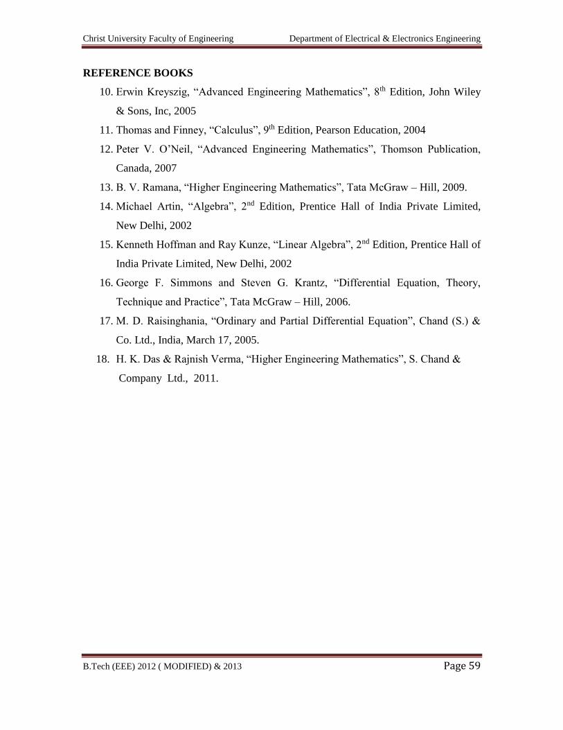
REFERENCE BOOKS
10. Erwin Kreyszig, “Advanced Engineering Mathematics”, 8th Edition, John Wiley
& Sons, Inc, 2005
11. Thomas and Finney, “Calculus”, 9th Edition, Pearson Education, 2004
12. Peter V. O’Neil, “Advanced Engineering Mathematics”, Thomson Publication,
Canada, 2007
13. B. V. Ramana, “Higher Engineering Mathematics”, Tata McGraw – Hill, 2009.
14. Michael Artin, “Algebra”, 2nd Edition, Prentice Hall of India Private Limited,
New Delhi, 2002
15. Kenneth Hoffman and Ray Kunze, “Linear Algebra”, 2nd Edition, Prentice Hall of
India Private Limited, New Delhi, 2002
16. George F. Simmons and Steven G. Krantz, “Differential Equation, Theory,
Technique and Practice”, Tata McGraw – Hill, 2006.
17. M. D. Raisinghania, “Ordinary and Partial Differential Equation”, Chand (S.) &
Co. Ltd., India, March 17, 2005.
18. H. K. Das & Rajnish Verma, “Higher Engineering Mathematics”, S. Chand &
Company Ltd., 2011.
Christ University Faculty of Engineering Department of Electrical & Electronics Engineering
B.Tech (EEE) 2012 ( MODIFIED) & 2013 Page 60
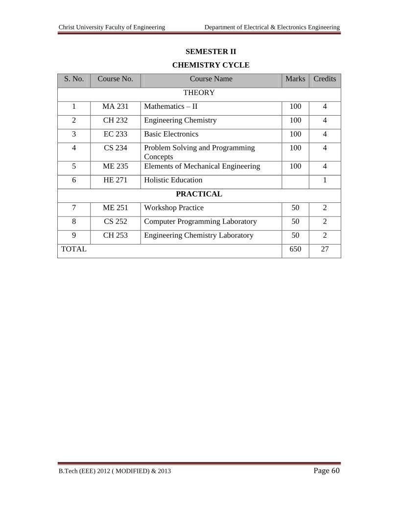
SEMESTER II
CHEMISTRY CYCLE
S. No. Course No. Course Name Marks Credits
THEORY
1 MA 231 Mathematics – II 100 4
2 CH 232 Engineering Chemistry 100 4
3 EC 233 Basic Electronics 100 4
4 CS 234 Problem Solving and Programming
Concepts
100 4
5 ME 235 Elements of Mechanical Engineering 100 4
6 HE 271 Holistic Education 1
PRACTICAL
7 ME 251 Workshop Practice 50 2
8 CS 252 Computer Programming Laboratory 50 2
9 CH 253 Engineering Chemistry Laboratory 50 2
TOTAL 650 27
Christ University Faculty of Engineering Department of Electrical & Electronics Engineering
B.Tech (EEE) 2012 ( MODIFIED) & 2013 Page 61
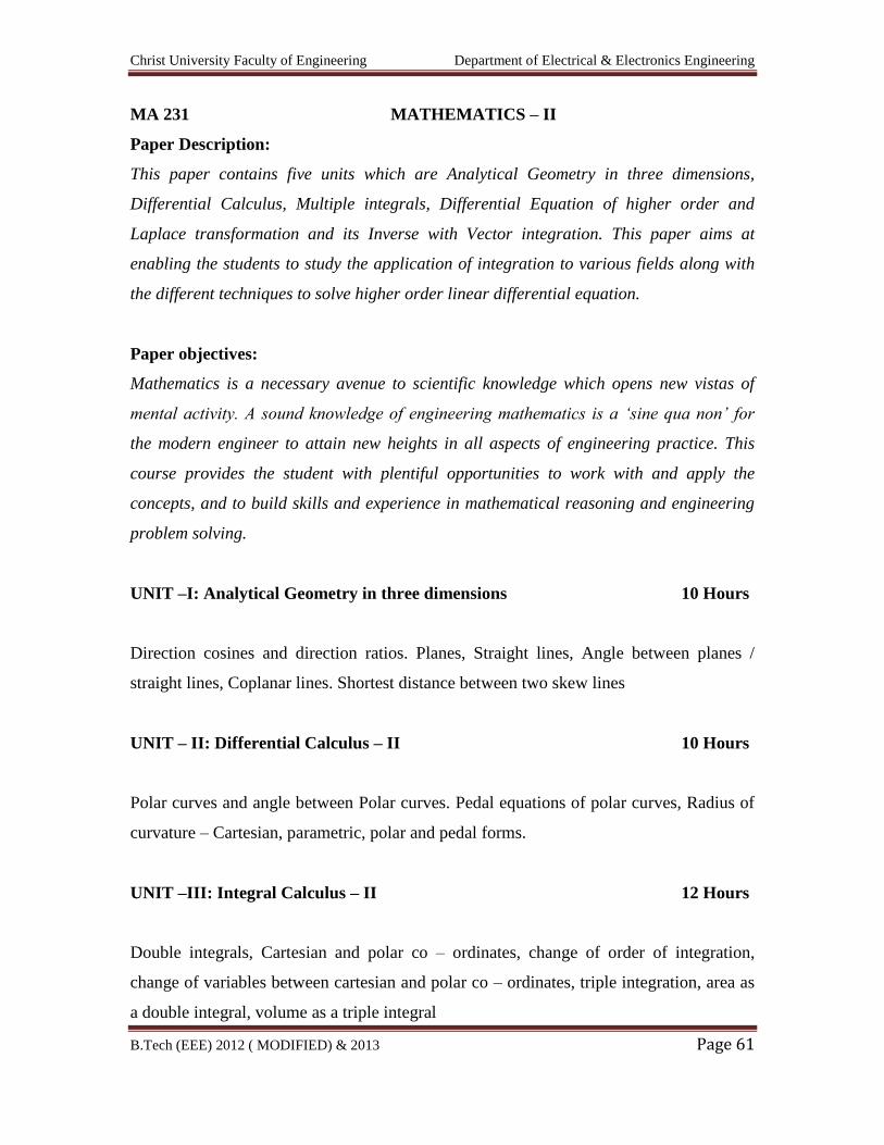
MA 231 MATHEMATICS – II
Paper Description:
This paper contains five units which are Analytical Geometry in three dimensions,
Differential Calculus, Multiple integrals, Differential Equation of higher order and
Laplace transformation and its Inverse with Vector integration. This paper aims at
enabling the students to study the application of integration to various fields along with
the different techniques to solve higher order linear differential equation.
Paper objectives:
Mathematics is a necessary avenue to scientific knowledge which opens new vistas of
mental activity. A sound knowledge of engineering mathematics is a ‘sine qua non’ for
the modern engineer to attain new heights in all aspects of engineering practice. This
course provides the student with plentiful opportunities to work with and apply the
concepts, and to build skills and experience in mathematical reasoning and engineering
problem solving.
UNIT –I: Analytical Geometry in three dimensions 10 Hours
Direction cosines and direction ratios. Planes, Straight lines, Angle between planes /
straight lines, Coplanar lines. Shortest distance between two skew lines
UNIT – II: Differential Calculus – II 10 Hours
Polar curves and angle between Polar curves. Pedal equations of polar curves, Radius of
curvature – Cartesian, parametric, polar and pedal forms.
UNIT –III: Integral Calculus – II 12 Hours
Double integrals, Cartesian and polar co – ordinates, change of order of integration,
change of variables between cartesian and polar co – ordinates, triple integration, area as
a double integral, volume as a triple integral
Christ University Faculty of Engineering Department of Electrical & Electronics Engineering
B.Tech (EEE) 2012 ( MODIFIED) & 2013 Page 62
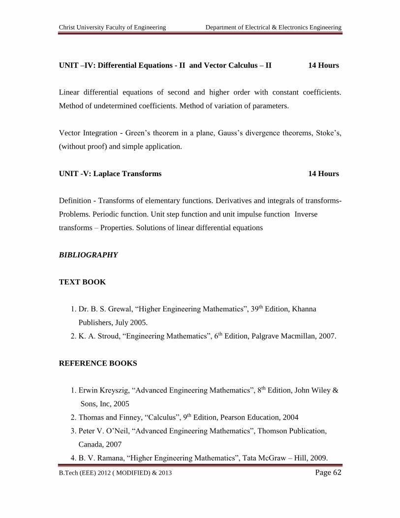
UNIT –IV: Differential Equations - II and Vector Calculus – II 14 Hours
Linear differential equations of second and higher order with constant coefficients.
Method of undetermined coefficients. Method of variation of parameters.
Vector Integration - Green’s theorem in a plane, Gauss’s divergence theorems, Stoke’s,
(without proof) and simple application.
UNIT -V: Laplace Transforms 14 Hours
Definition - Transforms of elementary functions. Derivatives and integrals of transforms-
Problems. Periodic function. Unit step function and unit impulse function Inverse
transforms – Properties. Solutions of linear differential equations
BIBLIOGRAPHY
TEXT BOOK
1. Dr. B. S. Grewal, “Higher Engineering Mathematics”, 39th Edition, Khanna
Publishers, July 2005.
2. K. A. Stroud, “Engineering Mathematics”, 6th Edition, Palgrave Macmillan, 2007.
REFERENCE BOOKS
1. Erwin Kreyszig, “Advanced Engineering Mathematics”, 8th Edition, John Wiley &
Sons, Inc, 2005
2. Thomas and Finney, “Calculus”, 9th Edition, Pearson Education, 2004
3. Peter V. O’Neil, “Advanced Engineering Mathematics”, Thomson Publication,
Canada, 2007
4. B. V. Ramana, “Higher Engineering Mathematics”, Tata McGraw – Hill, 2009.
Christ University Faculty of Engineering Department of Electrical & Electronics Engineering
B.Tech (EEE) 2012 ( MODIFIED) & 2013 Page 63
5. George F. Simmons and Steven G. Krantz, “Differential Equation, Theory,
Technique and Practice”, Tata McGraw – Hill, 2006.
6. M. D. Raisinghania, “Ordinary and Partial Differential Equation”, Chand (S.) &
Co. Ltd., India, March 17, 2005.
7. H. K. Das & Rajnish Verma, “Higher Engineering Mathematics”, S. Chand &
Company Ltd., 2011.
Christ University Faculty of Engineering Department of Electrical & Electronics Engineering
B.Tech (EEE) 2012 ( MODIFIED) & 2013 Page 64
CH 232 ENGINEERING CHEMISTRY
(Common for all branches)
PAPER DESCRIPTION:
This paper contains five units which are Chemical Energy Sources, Solar Energy,
Electrochemical Energy
Systems, Conversion and Storage of Electrochemical Energy Systems, Corrosion of
Science and Control. Metal
finishing and Electroless plating, Liquid Crystals and their Applications, High polymers
and Water Technology
This paper aims at enabling the students to know various energy sources. Corrosion and
its control metal finishing
and method of plating, crystals and their applications, types of polymers and water
technology covered in this
paper.
PAPER OBJECTIVES:
1. To familiarise the students on application oriented themes like the chemistry of
materials used in engineering discipline
2. To focus the students on the chemistry of compounds resulting from pollution,
waste generation and environmental degradation and to apply the knowledge in
solving these current environmental problems effectively.
LEVEL OF KNOWLEDGE: Basic
UNIT – I: CHEMICAL ENERGY SOURCES 9 Hours
Introduction to energy; Fuels - definition, classification, importance of hydrocarbons as
fuels; Calorific value-definition, Gross and Net calorific values (SI units). Determination
of calorific value of a solid / liquid fuel using Bomb calorimeter. Petroleum cracking-
fluidised catalytic cracking. Reformation of petrol. Knocking - mechanism, octane
Christ University Faculty of Engineering Department of Electrical & Electronics Engineering
B.Tech (EEE) 2012 ( MODIFIED) & 2013 Page 65
number, cetane number, prevention of knocking, anti-knocking agents, unleaded petrol;
synthetic petrol – Bergius process and Fischer Tropsch process; power alcohol. Solar
Energy : Photovoltaic cells- Introduction, definition, importance, working of a PV cell;
solar grade silicon, physical and chemical properties of silicon relevant to photovoltaics,
production of solar grade (crystalline) silicon and doping of silicon.
UNIT – II: ELECTROCHEMICAL ENERGY SYSTEMS (ELECTRODE
POTENTIAL AND CELLS) 7 Hours
Single electrode potential-dfinition, origin, sign conventions. Derivation of Nernst
equation. Standard electrode potential l-definition. Construction of Galvanic cell–
classification - primary, secondary and concentration cells, EMF of a cell–definition,
notation and conventions. Reference electrodes–calomel electrode, Ag/AgCl electrode.
Measurement of single electrode potential. Numerical problems on electrode potential
and EMF. Ion-selective electrode- glass electrode, determination of pH using glass
electrode
CONVERSION AND STORAGE OF ELECTROCHEMICAL ENERGY
7 Hours
BATTERY TECHNOLOGY –
Batteries-Basic concepts, battery characteristics. Classification of batteries–primary,
secondary and reserve batteries. Classical Batteries–Construction working and
applications of Zn–air, Nickel-Metal hydride and Lithium-MnO2 batteries, Fuel Cells -
Introduction, types of fuel cells-Alkaline, Phosphoric acid and Molten carbonate fuel
cells. Solid polymer electrolyte and solid oxide fuel cells. Construction and working of
H2O2and Methanol-Oxygen fuel cell
UNIT – III: CORROSION SCIENCE 7 Hours
Christ University Faculty of Engineering Department of Electrical & Electronics Engineering
B.Tech (EEE) 2012 ( MODIFIED) & 2013 Page 66
Corrosion - definition, Chemical corrosion and Electro-chemical theory of corrosion,
Types of corrosion, Differential metal corrosion, Differential aeration corrosion (pitting
and water line corrosion), Stress corrosion. Factors affecting the rate of corrosion,
Corrosion control: Inorganic coatings – Anodizing and Phosphating, Metal coatings –
Galvanization and Tinning, Corrosion Inhibitors, Cathodic and Anodic protection
METAL FINISHING 7 Hours
Technological importance of metal finishing. Significance of polarization, decomposition
potential and over-voltage in electroplating processes. Electroplating – Process, Effect of
plating variables on the nature of electro deposit, surface preparation and electroplating
of Cr and Au. Electroless Plating, Distinction between electroplating and electroless
plating, advantages of electroless plating. Electroless plating of copper on PCB and
Nickel
UNIT – IV LIQUID CRYSTALS AND THEIR APPLICATIONS: 6 Hours
Introduction, classification-Thermotropic and Lyotropic with examples. Types of
mesophases- nematic, chiral nematic (cholesteric), smectic and columnar. Homologues
series (PAA and MBBA); Applications of liquid crystals in display systems
HIGH POLYMERS: 7 Hours
Definition, Classification - Natural and synthetic with examples. Polymerization –
definition, types of polymerization – Addition and Condensation with examples.
Mechanism of polymerization - free radical mechanism (ethylene as an example),
Methods of polymerization - bulk, solution, suspension and emulsion polymerization.
Glass transition temperature, structure and property relationship. Compounding of resins.
Synthesis, properties and applications of Teflon. PMMA, Polyurethane and Phenol –
formaldehyde resin. Elastomers - Deficiencies of natural rubber and advantages of
synthetic rubber. Synthesis and application of Neoprene, Butyl rubber. Adhesives-
Christ University Faculty of Engineering Department of Electrical & Electronics Engineering
B.Tech (EEE) 2012 ( MODIFIED) & 2013 Page 67
Manufacture and applications of Epoxy resins. Conducting polymers - definition,
mechanism of conduction in polyacetylene. Structure and applications of conducting
Polyaniline
UNIT – V WATER TECHNOLOGY: 7 Hours
Impurities in water, Water analysis - Determination of different constituents in water -
Hardness, Alkalinity, Chloride, Fluoride, Nitrate, Sulphate and Dissolved Oxygen.
Numerical problems on hardness and alkalinity. Biochemical Oxygen Demand and
Chemical Oxygen Demand. Numerical problems on BOD and COD. Sewage treatment.
Potable water, purification of water - Flash evaporation, Electro dialysis and Reverse
Osmosis. Hazardous chemicals with ill effects
INSTRUMENTAL METHODS OF ANALYSIS: 2 HOURS
Theory, Instrumentation and Applications of Colorimetry, Potentiometry, Conductometry
BIBILOGRAPHY
TEXT BOOKS
1. Dr. B.S. Jai Prakash, “Chemistry for Engineering Students”, Subhas Stores,
Bangalore,
Revised Edition 2009
2. M. M. Uppal, “Engineering Chemistry”, Khanna Publishers, Sixth Edition, 2001
3. Jain and Jain, “A text Book of Engineering Chemistry”, S. Chand & Company
Ltd. New Delhi, 2009
REFERENCE BOOKS
1. Alkins P.W. “physical chemistry” ELBS IV edition 1998, London
2. F. W. Billmeyer, “Text Book of Polymer Science”, John Wiley & Sons, 1994
3. G. W. Gray and P. A. Winsor, “Liquid crystals and plastic crystals”, Vol - I, Ellis
Horwood series in Physical Chemistry, New York. (P. No. 106-142)
4. M. G. Fontana, “Corrosion Engineering”, Tata Mc Graw Hill Publications 1994.
5. Stanley E. Manahan, “Environmental Chemistry”, Lewis Publishers, 2000
Christ University Faculty of Engineering Department of Electrical & Electronics Engineering
B.Tech (EEE) 2012 ( MODIFIED) & 2013 Page 68
6. B. R. Puri, L. R. Sharma & M. S. Pathania, ”Principles of Physical Chemistry”,
S. Nagin Chand & Co., 33rd Ed.,1992
7. Kuriakose J.C. and Rajaram J. “ Chemistry in Engineering and Technology” Vol I
& II, Tata Mc Graw – Hill Publications Co Ltd, NewDelhi, 1996.
Christ University Faculty of Engineering Department of Electrical & Electronics Engineering
B.Tech (EEE) 2012 ( MODIFIED) & 2013 Page 69
EC 233 BASIC ELECTRONICS
(Common for all branches)
PAPER DESCRIPTION:
The course aims to develop the skills of the students in the areas of electronics by
learning fundamentals. This will be necessary for their effective studies in a large
number of engineering subjects like Electronics circuits and devices, Digital
Electronics, communication systems. The course will also serve as a prerequisite
for post graduate and specialized studies and research.
PAPER OBJECTIVES:
To impart basic knowledge about electronic and digital systems
To give basic ideas about various communication systems
LEVEL OF KNOWLEDGE: Basic
UNIT – I:
Introduction to semiconductors and basic diode theory 9 + 3 Hours
Conductors, semiconductors and insulators, Intrinsic and Extrinsic semiconductors, Flow
of charge carriers in a semiconductor, Mass Action Law, energy levels and barrier
potential, PN junction as a diode, Unbiased diode, forward bias diode, reverse bias, VI
characteristics of a diode, Variation of diode parameters with temperature. Ideal diodes,
diode approximations, resistance of a diode, Load lines, comparison between Silicon and
Germanium
UNIT – II:
Semiconductor diode applications 9 + 3 Hours
Half-wave rectifier, ripple factor and efficiency, Full-wave and bridge rectifier, ripple
factor and efficiency, Peak inverse voltage, working of capacitor input filter,
Approximate analysis of capacitor filter, Zener diode characteristics, Zener and
Avalanche breakdown, Zener diode voltage regulator, power supply performance,
Clipper and Clamper.

Christ University Faculty of Engineering Department of Electrical & Electronics Engineering
B.Tech (EEE) 2012 ( MODIFIED) & 2013 Page 70
UNIT – III :
Bipolar Junction Transistors 9 + 3 Hours
Bipolar junction transistor, transistor voltages and currents, Unbiased transistor, Biased
transistor, Transistor configurations- CB, CE, CC, DC load line Base Bias, Collector to
Base Bias, Voltage divider Bias, Comparison of basic bias circuits, Bias circuit design,
Comparison of basic bias circuits.
UNIT – IV :
Introduction to Operational Amplifiers & Oscillators 9 + 3 Hours
Block diagram, Op-amp transfer characteristics, Basic Op-amp parameters and its value
for IC 741- offset voltage and current, input and output impedance, Gain, slew rate,
bandwidth, CMRR, Concept of negative feedback, Inverting and Non-inverting
amplifiers, Summing Amplifier, Subtractor, integration, differentiation, Voltage follower,
Introduction to Oscillators, the Barkhausen Criterion for Oscillations, Applications of
Oscillator
UNIT – V :
Digital Electronics 9 + 3 Hours
Sampling theorem, Introduction, decimal system, Binary, Octal and Hexadecimal number
systems, addition and subtraction, fractional number, Binary Coded Decimal numbers.
Boolean algebra, Logic gates, Half-adder, Full-adder, Parallel Binary adder.
BIBILOGRAPHY:
TEST BOOKS:
1. "Electronic Devices and Circuit Theory", 3rd Edition, Robert L Boylestad &
Louis Nashelsky
2. Fundamentals of Electrical Engineering, 2nd Edition, L S Bobrow
3. Albert Malvino, David. J. Bates, “Electronic Principles”, 7th Edition, Tata
McGraw Hill, 2007
4. Morris Mano, “Digital Logic and Computer Design”, PHI, EEE
5. "Digital Design", John F Wakerly

Christ University Faculty of Engineering Department of Electrical & Electronics Engineering
B.Tech (EEE) 2012 ( MODIFIED) & 2013 Page 71
REFERENCE BOOKS:
1. Jacob Millman, Christos C. Halkias“Electronic Devices and Circuits”, TMH, 1991
Reprint 2001
2. David. A. Bell, “Electronic Devices and Circuits”, PHI, New Delhi, 2004
3. Albert Paul Malvino, Donald P Leach, Goutamsaha, “Digital Principles and
applications”, 6th Edition, Tata McGraw Hill, 2007.
4. Roy Choudhary and Shail Jain, “Linear Integrated Circuits”,ThirdEdition,New Age
international Publishers,2007
Christ University Faculty of Engineering Department of Electrical & Electronics Engineering
B.Tech (EEE) 2012 ( MODIFIED) & 2013 Page 72
CS234 PROBLEM SOLVING AND PROGRAMMING CONCEPTS
(Common for all branches)
PAPER DESCRIPTION:
This paper contains five units which gives the programming concepts of C Language.
This paper aims at enabling the students to learn C programming Language in detail.
PAPER OBJECTIVES:
1. To develop skill in problem solving concepts through learning C programming.
LEVEL OF KNOWLEDGE: Basic
Unit – I: 12 Hours
Algorithms and Flowcharts:
Algorithms, Flowcharts, Divide and conquer strategy. Examples on algorithms and
flowcharts.
Constants, Variables, and Data types: Characters set, C tokens, Keywords and Identifiers,
Constants, Variables, Data types, Declaration of variables.
Operators and Expressions:
Arithmetic operators, Relational operators, Logical operators, Assignment operators,
Increment and Decrement operators, Conditional operator, Bitwise operators, Special
operators, Arithmetic expressions, Evaluation of expressions, Precedence of Arithmetic
operators, Type conversions in expressions, Operator precedence and associatively.
Christ University Faculty of Engineering Department of Electrical & Electronics Engineering
B.Tech (EEE) 2012 ( MODIFIED) & 2013 Page 73
Unit – II: 12 Hours
Managing Input and Output Operations:
Reading a character, writing a character, Formatted Input, Formatted Output
Decision making and Branching:
Decision making with if statement, Simple if statement, The if…else statement, Nesting
of if…else statements, The else … if ladder, The switch statement, The ?: operator, The
Goto statement
Looping:
The while statement, The do statement, The for statement, Jumps in Loops
Unit – III: 13 Hours
Arrays:
One-dimensional Arrays, Declaration of one-dimensional Arrays, Initialization of one-
dimensional Arrays, Two-dimensional Arrays, Initializing two-dimensional Arrays.
User-defined Functions:
Need for User-defined Functions, A multi-function Program, Elements of user - defined
Functions, Definition of Functions, Return Values and their types, Function Calls,
Function Declaration, Category of Functions, No Arguments and no Return Values,
Arguments but no Return Values, Arguments with Return Values, No Argument but
Returns a Value, Functions that Return Multiple Values.
Unit – IV: 10 Hours
Pointers:
Understanding the pointers, Accessing the Address of a Variable, Declaring Pointer
Variables, Initialization of Pointer Variables, Accessing a Variable through its Pointer,
Pointer Expressions, Pointer Increments and Scale Factor, Pointers and Arrays, Pointers
and Character Strings, Pointers as Function Arguments, Functions Returning Pointers.
Christ University Faculty of Engineering Department of Electrical & Electronics Engineering
B.Tech (EEE) 2012 ( MODIFIED) & 2013 Page 74
Unit – V: 13 Hours
Strings, Structure, Union, Files:
Strings: String concepts, C strings, String I/O functions, Array of strings, String
manipulation function, Memory formatting, Derived types-Enumerated, Structure, and
Union: The type definition, Enumerated types, Structure, Accessing structures, Complex
structures, Array of structures, Structures and functions, Union , Files: Classification of
Files, Standard Library Functions for Files
BIBILOGRAPHY:
TEXT BOOKS:
1. Deitel and Deitel, "C How to Program", Prentice Hall 2010.
2. Anil Bikas Chaudhuri, "The Art of Programming through Flowcharts and
Algorithms", Firewall Media.
REFERENCE BOOKS:
1. Introduction to Computer Science, ITL Education Solutions Ltd., Pearson
Education, 2007.
2. E. Balagurusamy, “Programming in ANSI C”, Tata McGraw Hill – III Edition.
3. V. Rajaraman, “Fundamentals of Computers”, 4th Edition, PHI 2005.
4. M. G. V. Murthy, “Programming Techniques through C”, Pearson Education,
2007.
5. Yashvant Kanetkar, “Let Us C”, BPB Publications - 8th Edition, 2008.
Christ University Faculty of Engineering Department of Electrical & Electronics Engineering
B.Tech (EEE) 2012 ( MODIFIED) & 2013 Page 75
ME 23 5 ELEMENTS OF MECHANICAL ENGINEERING
(Common for all branches)
PAPER DESCRIPTION:
Mechanical Engineering basically deals with three basic concepts Design engineering,
Thermal engineering & Manufacturing engineering, this subject ELEMENTS OF
MECHANICAL ENGINEERING gives the basic insight of theoretically knowledge of these
aspects.
PAPER OBJECTIVES:
To familiarize with
1. The Source of Energy and Power Generation.
2. The various metal processing and metal working.
3. The Basic theory of machine tools.
LEVEL OF KNOWLEDGE: Basic
UNIT – I: 9 Hours
Energy and Steam Forms:
Sources and Classification of energy, Utilization of energy with simple block diagrams,
Steam formation. Types of steam, Steam properties – Specific Volume, Enthalpy and Internal
energy. (simple numerical problems) Steam boilers classification, Lancashire boiler, Babcock
and Wilcox boiler mountings, accessories, their locations and application. (No sketches for
mountings and accessories).
UNIT-II 16 Hours
TURBINES:
Steam turbines–Classification, Principle of operation of Impulse and reaction. Delaval’s
turbine, Parson’s turbine. Compounding of Impulse turbines. Gas turbines –
Christ University Faculty of Engineering Department of Electrical & Electronics Engineering
B.Tech (EEE) 2012 ( MODIFIED) & 2013 Page 76
Classification, Working principles and Operations of Open cycle and Closed cycle gas
turbines. Water turbines –Classification, Principles and operations of Pelton wheel,
Francis turbine and Kaplan turbine
INTERNAL COMBUSTION ENGINES:
Classification, I.C. Engines parts, 2/4 – Stroke Petrol and 4-stroke diesel engines. P-V
diagrams of Otto and Diesel cycles. Simple problems on indicated power, brake power,
indicated thermal efficiency, brake thermal efficiency, mechanical efficiency and specific
fuel consumption.
UNIT – III: 9 Hours
REFRIGERATION AND AIR CONDITIONING:
Refrigerants, properties of refrigerants, list of commonly used refrigerants. Refrigeration
- Definitions - Refrigerating effect, Ton of Refrigeration, Ice making capacity, COP,
Relative COP, Unit of Refrigeration. Principle and working of vapor compression
refrigeration and vapor absorption refrigeration. Principles and applications of air
conditioners, Room air conditioner
UNIT – IV: 16 Hours
LATHE AND DRILLING:
Machines Lathe - Principle of working of a Centre Lathe. Parts of a lathe. Operations on
lathe - Turning, Facing, Knurling, Thread Cutting, Drilling, Taper Turning by Tailstock
offset method and Compound slide swiveling method. Specification of Lathe.
Drilling Machine – Principle of working and classification of Drilling Machines. Bench
Drilling Machine, Radial Drilling Machine. Operations on Drilling Machine - Drilling,
Boring, Reaming, Tapping, Counter Sinking, Counter Boring and Spot facing.
Specification of radial drilling machine.
Christ University Faculty of Engineering Department of Electrical & Electronics Engineering
B.Tech (EEE) 2012 ( MODIFIED) & 2013 Page 77
MILLING AND GRINDING MACHINES:
Milling Machine – Principle of Milling, Types of Milling Machines. Principle &
Working of Horizontal and Vertical Milling Machines. Milling Processes - Plane Milling,
End Milling, Slot Milling, Angular Milling, Form Milling, Straddle Milling and Gang
Milling. Specification of Universal Milling Machine.
Grinding Machine – Principle and classification of Grinding Machines. Abrasives -
Definition, types and Applications. Bonding Materials. Type of Grinding Machines,
Principle and Working of Surface Grinding, Cylindrical Grinding and Centerless
Grinding.
UNIT – V: 10 Hours
JOINING PROCESSES, LUBRICATION AND BEARINGS:
Soldering, Brazing and Welding, Definitions. Classification and method of Soldering,
Brazing and Welding and Differences. Brief Description of Arc Welding and Oxy -
Acetylene Welding Lubrication and Bearings Lubricants - Classification and properties.
Screw cap, Tell - Tale, Drop feed, Wick feed and Needle Lubricators. Ring, Splash and
Full pressure lubrication. Classification of Bearings, Bushed bearing, Pedestal bearing,
Pivot bearing, Collar Bearings and Antifriction Bearings.
POWER TRANSMISSION: Belt Drives - Classification and applications, Derivations
on Length of belt. Definitions - Velocity ratio, Creep and slip, Idler pulley, stepped pulley
and fast & loose pulley. Gears - Definitions, Terminology, types and uses. Gear Drives
and Gear Trains – Definitions and classifications, Simple problems.
BIBILOGRAPHY:
TEXT BOOKS:
1. K.R. Gopalkrishna, “A text Book of Elements of Mechanical
Engineering”, Subhash Publishers, Bangalore.
Christ University Faculty of Engineering Department of Electrical & Electronics Engineering
B.Tech (EEE) 2012 ( MODIFIED) & 2013 Page 78
2. S. Trymbaka Murthy, “A Text Book of Elements of Mechanical
Engineering”, 3rd revised edition,I .K. International Publishing House
Pvt. Ltd., New Delhi. 2010.
3. Dr. R. P. Reddy, N. Kapilan, “Elements of Mechanical Engineering”, 1st
Edition, Himalaya Publishing House, New Delhi.
REFERENCE BOOKS:
1. SKH Chowdhary, AKH Chowdhary, Nirjhar Roy, “The Elements of
Workshop Technology”, Vol. I & II, Media Promotors and Publishers,
Mumbai.
2. Ghosh Mallik, “Manufacturing Technology”, TMH. HMT, Production
Technology, TMH
Christ University Faculty of Engineering Department of Electrical & Electronics Engineering
B.Tech (EEE) 2012 ( MODIFIED) & 2013 Page 79
HE 271 HOLISTIC EDUCATION
(Common for all branches)
PAPER DESCRIPTION:
This paper contains three units which are Introduction to Life skills, Personal skills,
Inter-personal Skills and Societal Skills. This paper aims at enabling the students to
various skills in life.
PAPER OBJECTIVE:
Holistic development of the individual adult in every student
Knowing life and its principles
Broadening the outlook to life
Training to face the challenges of life
Confidence creation and personality development
Emotional control and stress management
Creating awareness on duties, rights and obligations as member of the Society
Realizing Personal Freedom-its limits and limitations
Developing the attitude to be a contributor and giver
Realizing the real happiness in life
LEVEL OF KNOWLEDGE: Basic
1. INTRODUCTION TO LIFE SKILLS (I Semester) 4 Hours
2. PERSONAL SKILLS
Creative thinking and Problem solving (I Semester)
Critical thinking and Decision making(I Semester)
Study skills and Time management(II Semester)
Health (II Semester)
Christ University Faculty of Engineering Department of Electrical & Electronics Engineering
B.Tech (EEE) 2012 ( MODIFIED) & 2013 Page 80
3. INTER-PERSONAL SKILLS 4 Hours
Non verbal Communication(I Semester)
Empathy and active listening(I Semester)
Assertiveness Training (II Semester)
Conflict Management(II Semester)
4. SOCIETAL SKILLS 4 Hours
Human Rights(I Semester)
Civil Society and Civic sense(I Semester)
Equality and Justice(II Semester)
Gender Sensation(II Semester)
TEXT BOOK: Holistic Education by Christ College publication, Bangalore-560029
Christ University Faculty of Engineering Department of Electrical & Electronics Engineering
B.Tech (EEE) 2012 ( MODIFIED) & 2013 Page 81
ME 251 WORKSHOP PRACTICE
(Common for all branches)
PAPER DESCRIPTION:
This paper provides working knowledge of fitting welding, sheet metal and carpentary.
PAPER OBJECTIVES:
To provide the students with the hands on experience on different trades of engineering
like fitting, welding, carpentary & sheet metal.
LEVEL OF KNOWLEDGE: Working
1. Fitting
a) Study of fitting tools
b) Study of fitting operations & joints
c) Minimum 5 models involving rectangular, triangular, semi circular and dovetail
joints.
2. Welding
d) Study of electric arc welding tools & equipments
e) Minimum 4 Models - electric arc welding - Butt joint, Lap joint, T joint & L joint.
3. Sheet metal
f) Study of development of surfaces
g) Minimum 03 models ( Tray,Funnel,Cone)
4. Study and demonstration of Carpentry tools, joints and operations.
TEXT BOOK:
S. K. H. Choudhury, A. K. H. Choudhury, Nirjhar Roy, “The Elements of Workshop
Technology”, Vol 1 & 2, Media Publishers, Mumbai
Christ University Faculty of Engineering Department of Electrical & Electronics Engineering
B.Tech (EEE) 2012 ( MODIFIED) & 2013 Page 82
COMPUTER PROGRAMMING LABORATORY- CS 252
(Common for all branches)
PAPER DESCRIPTION:
Paper contains the programs which include Operations in C, Loop Control Structures, and
Function sand file handling methods. This paper aims at enabling the students to know
fundamentals of computer concepts and C programming.
PAPER OBJECTIVES:
To impart the basic concepts of computer and information technology
To develop skill in problem solving concepts through learning C programming in
practical approach.
LEVEL OF KNOWLEDGE: Basic/working
PART- A
1. Write a C program to find and output all the roots of a given quadratic equation,
for non-zero coefficients. (Using if…else statement)
2. Write a C program to simulate a simple calculator that performs arithmetic
operations like addition, subtraction, multiplication, and division only on integers.
Error message should be reported, if any attempt is made to divide by zero.
(Using switch statement)
3. Write a C program to generate and print first ‘N’ Fibonacci numbers. (Using
looping constructs)
Christ University Faculty of Engineering Department of Electrical & Electronics Engineering
B.Tech (EEE) 2012 ( MODIFIED) & 2013 Page 83
4. Write a C program to find the GCD and LCM of two integers and output the
results along with the given integers. Use Euclid’s algorithm. (Using looping
constructs)
5. Write a C program to reverse a given four digit integer number and check whether
it is a palindrome or not. Output the given number with suitable message. (Using
looping constructs)
6. Write a C program to find whether a given number is prime or not. Output the
given number with suitable message. (Using looping constructs)
PART - B
7. Write a C program to input N real numbers in into a single dimension array.
Conduct linear search for a given key integer number and report success or failure
in the form of a suitable message.
8. Write a C program to input N integer numbers into a single dimension array. Sort
them in ascending order using bubble sort technique. Print both the given array
and the sorted array with suitable headings.
9. Write a C program to evaluate the given polynomial f(x) = a4x4 +a3x
3 + a2x2 +
a1x1 + a0 for given value of x and the coefficients using Horner’s method. (Using
single dimension arrays to store coefficients)
10. Write a C program to input N real numbers in ascending order into a single
dimension array. Conduct a binary search for a given key integer number and
report success or failure in the form of a suitable message.
11. Write a C program to input N integer numbers into a single dimension array. Sort
them in ascending order using bubble sort technique. Print both the given array
and the sorted array with suitable headings.
12. Write C user defined functions
i. To input N real numbers into a single dimension array.
ii. Compute their mean.
Christ University Faculty of Engineering Department of Electrical & Electronics Engineering
B.Tech (EEE) 2012 ( MODIFIED) & 2013 Page 84
iii. Compute their variance
iv. Compute their standard deviation.
Using these functions, write a C program to input N real numbers into a single
dimension array, and compute their mean, variance & standard deviation. Output
the computed results with suitable headings.
13. Write C user defined functions
i. To read the elements of a given matrix of size M x N.
ii. To print the elements of a given matrix of size M x N.
iii. To compute the product of two matrices.
Using these functions, write a C program to read two matrices A(M x N) and B(P
x Q) and compute the product of A and B after checking compatibility for
multiplication. Output the input matrices and the resultant matrix with suitable
headings and format (Using two dimension arrays)
14. Write a C program to read a matrix A(M x N) and to find the following using user
defined functions:
i. Sum of the elements of the specified row.
ii. Sum of the elements of the specified column.
iii. Sum of all the elements of the matrix.
Output the computed results with suitable headings.
15. Write a C Program to create a sequential file with at least 5records, each record
having USN, name, mark1, mark2, and mark3. Write necessary functions
i. To display all the records in the file.
ii. To search for a specific record based on the USN. In case the record is not
found, suitable message should be displayed. Both the options in this case
must be demonstrated.
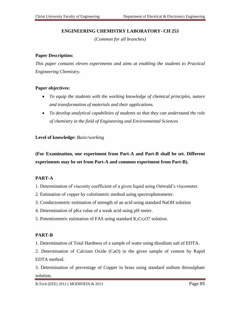
Christ University Faculty of Engineering Department of Electrical & Electronics Engineering
B.Tech (EEE) 2012 ( MODIFIED) & 2013 Page 85
ENGINEERING CHEMISTRY LABORATORY- CH 253
(Common for all branches)
Paper Description:
This paper contains eleven experiments and aims at enabling the students to Practical
Engineering Chemistry.
Paper objectives:
To equip the students with the working knowledge of chemical principles, nature
and transformation of materials and their applications.
To develop analytical capabilities of students so that they can understand the role
of chemistry in the field of Engineering and Environmental Sciences
Level of knowledge: Basic/working
(For Examination, one experiment from Part-A and Part-B shall be set. Different
experiments may be set from Part-A and common experiment from Part-B).
PART-A
1. Determination of viscosity coefficient of a given liquid using Ostwald’s viscometer.
2. Estimation of copper by colorimetric method using spectrophotometer.
3. Conductometric estimation of strength of an acid using standard NaOH solution
4. Determination of pKa value of a weak acid using pH meter.
5. Potentiometric estimation of FAS using standard K2Cr2O7 solution.
PART-B
1. Determination of Total Hardness of a sample of water using disodium salt of EDTA.
2. Determination of Calcium Oxide (CaO) in the given sample of cement by Rapid
EDTA method.
3. Determination of percentage of Copper in brass using standard sodium thiosulphate
solution.
Christ University Faculty of Engineering Department of Electrical & Electronics Engineering
B.Tech (EEE) 2012 ( MODIFIED) & 2013 Page 86
4. Determination of Iron in the given sample of Haematite ore solution using potassium
dichromate crystals by external indication method.
5. Determination of Chemical Oxygen Demand (COD) of the given industrial waste
Water sample. (for demonstration)
6. Determination of Dissolved Oxygen in the given water sample by Winkler method.
(for demonstration)
Examination – First experiment is a common experiment from Part B. Second
experiment is different, from Part A or Part B.
Reference books:
1. J. Bassett, R.C. Denny, G.H. Jeffery, “Vogels text book of quantitative inorganic
analysis”,4th
Edition
2. Sunita and Ratan “Practical Engineering Chemistry”
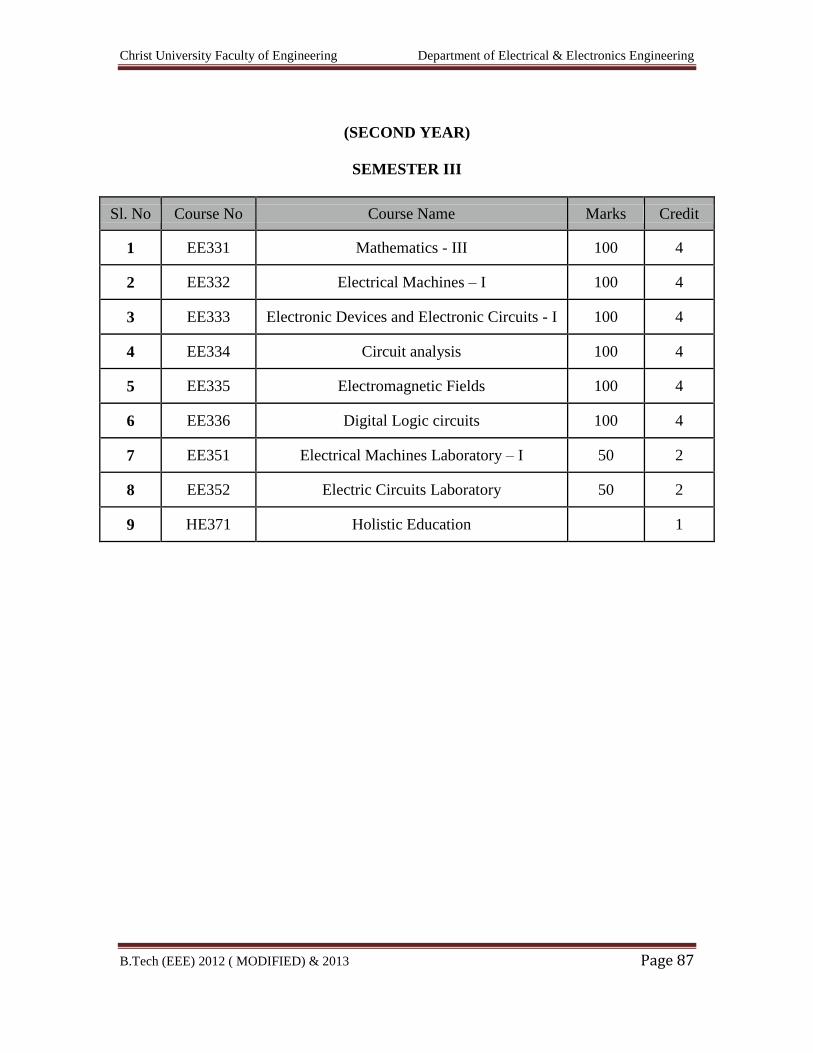
Christ University Faculty of Engineering Department of Electrical & Electronics Engineering
B.Tech (EEE) 2012 ( MODIFIED) & 2013 Page 87
(SECOND YEAR)
SEMESTER III
Sl. No Course No Course Name Marks Credit
1 EE331 Mathematics - III 100 4
2 EE332 Electrical Machines – I 100 4
3 EE333 Electronic Devices and Electronic Circuits - I 100 4
4 EE334 Circuit analysis 100 4
5 EE335 Electromagnetic Fields 100 4
6 EE336 Digital Logic circuits 100 4
7 EE351 Electrical Machines Laboratory – I 50 2
8 EE352 Electric Circuits Laboratory 50 2
9 HE371 Holistic Education 1
Christ University Faculty of Engineering Department of Electrical & Electronics Engineering
B.Tech (EEE) 2012 ( MODIFIED) & 2013 Page 88
EE331 MATHEMATICS III
Paper Description:
To extend student’s mathematical maturity and ability to deal with abstraction and to
introduce most of the basic terminologies used in Electrical and Electronics courses and
application of ideas to solve practical problems.
Paper Objective:
At the end of the course the students would be capable of mathematically formulating
certain practical problems in terms of partial differential equations, solve them and
physically interpret the results. Have gained a well founded knowledge of Fourier series,
their different possible forms and the frequently needed practical harmonic analysis that
an engineer may have to make from discrete data. Have obtained capacity to formulate
and identify certain boundary value problems encountered in engineering practices,
decide on applicability of the Fourier series method of solution, solve them and interpret
the results. When huge amounts of experimental data are involved, the methods
discussed on numerical methods will be useful in constructing approximate polynomial
and equations to represent the data and to find the intermediate values and solution.
UNIT – I: Coordinate Systems 10 Hours
Curvilinear Coordinate System, Gradient, divergent, curl and Laplacian in cylindrical and
Spherical Coordinate system, Cylindrical Coordinates, Spherical Coordinates,
Transformation between systems.
UNIT – II: Partial Differential Equation 12 Hours
Formation of partial differential equations by elimination of arbitrary constants and
arbitrary functions – Solution of standard types of first order partial differential equations
– Lagrange’s linear equation – Linear partial differential equations of second and higher
order with constant coefficients.
Christ University Faculty of Engineering Department of Electrical & Electronics Engineering
B.Tech (EEE) 2012 ( MODIFIED) & 2013 Page 89
UNIT – III: Fourier Series & Fourier Transform 14 Hours
Fourier series – Odd and even functions – Half range Fourier sine and cosine series –
Complex form of Fourier series – Harmonic Analysis. Discrete Fourier Sine and Cosine
transform
Complex Fourier transform – Sine and Cosine transforms – Properties – Transforms of
simple functions – Convolution theorem – Parseval’s identity. Solution of equations
using Fourier transform, Limitation of Fourier series and Fourier transform and need for
Wavelet.
UNIT – IV: Numerical Methods 12 Hours
Linear interpolation methods (method of false position) – Newton’s method – Solution of
linear system of equations by Gaussian elimination and Gauss-Jordon methods- Iterative
methods: Gauss-Seidel methods- Inverse of a matrix by Gauss Jordon method –
Eigenvalue of a matrix by power method.
Taylor series method – Euler method, Fourth order Runge – Kutta method for solving
first and second order equations and modified Euler methods –
UNIT – V: Z – Transform and Difference Equations 12 Hours
Z-transform - Elementary properties – Inverse Z – transform – Convolution theorem -
Formation of difference equations – Solution of difference equations using Z - transform.
BIBILOGRAPHY:
TEXT BOOKS
1. Grewal, B.S., “Higher Engineering Mathematics”, Thirty Sixth Edition , Khanna
Publishers, Delhi, 2005.
2. Kandasamy, P., Thilagavathy, K. and Gunavathy, K., “Numerical Methods”, S.
Chand Co. Ltd., New Delhi, 2003.
Christ University Faculty of Engineering Department of Electrical & Electronics Engineering
B.Tech (EEE) 2012 ( MODIFIED) & 2013 Page 90
REFERENCES
1. Narayanan, S., Manicavachagom Pillay, T.K. and Ramaniah, G., “Advanced
Mathematics for Engineering Students”, Volumes II and III, S. Viswanathan (Printers
and Publishers) Pvt. Ltd. Chennai, 2002.
2. Ramana B.V., “Higher Engineering Mathematics”, Tata McGraw – Hill Publishing
Company. New Delhi, 2009.
3. Churchill, R.V. and Brown, J.W., “Fourier Series and Boundary Value Problems”,
Fourth Edition, McGraw-Hill Book Co., Singapore, 1987.
4. T.Veera Rajan “Engineering Mathematics [For Semester III]. Third Edition. Tata
McGraw-Hill Publishing Company. New Delhi, 2007
5. Gerald, C.F, and Wheatley, P.O, “Applied Numerical Analysis”, Sixth Edition,
Pearson Education Asia, New Delhi, 2002.
6. Balagurusamy, E., “Numerical Methods”, Tata McGraw-Hill Pub. Co. Ltd, New
Delhi, 1999.
7. Burden, R.L and Faires, T.D., “Numerical Analysis”, Seventh Edition, Thomson Asia
Pvt. Ltd., Singapore, 2002.
8. S. L. Loney, “Plane Trigonometry”, Cambridge: University Press.
Christ University Faculty of Engineering Department of Electrical & Electronics Engineering
B.Tech (EEE) 2012 ( MODIFIED) & 2013 Page 91
EE332 ELECTRICAL MACHINES – I
AIM
To expose the students to the concepts of electromechanical energy conversions
in D.C. machines and energy transfer in transformers and to analyse their performance.
OBJECTIVES
i. To introduce the concept of rotating machines and the principle of electromechanical
energy conversion in single and multiple excited systems.
ii. To understand the generation of D.C. voltages by using different type of generators
and study their performance.
iii. To study the working principles of D.C. motors and their load characteristics, starting
and methods of speed control.
iv. To familiarize with the constructional details of different type of transformers,
working principle and their performance.
v. To estimate the various losses taking place in D.C. machines and transformers and to
study the different testing method to arrive at their performance.
UNIT I: BASIC CONCEPTS OF ROTATING MACHINES 8 + 3
Principles of electromechanical energy conversion – Single and multiple excited systems
– m.m.f of distributed A.C. windings – Rotating magnetic field – Generated voltage –
Torque in round rotor machine.
UNIT II: DC GENERATORS 8 + 3
Constructional details – emf equation – Methods of excitation – Self and separately
excited generators – Characteristics of series, shunt and compound generators – Armature
reaction and commutation – Parallel operation of DC shunt and compound generators.
UNIT III: DC MOTORS 9 + 3
Principle of operation – Back emf and torque equation – Characteristics of series, shunt
and compound motors – Starting of DC motors – Types of starters – Speed control of DC
series and shunt motors.
UNIT IV: TRANSFORMERS 12 + 3
Constructional details of core and shell type transformers – Types of windings – Principle
of operation – emf equation – Transformation ratio – Transformer on no-load –
Christ University Faculty of Engineering Department of Electrical & Electronics Engineering
B.Tech (EEE) 2012 ( MODIFIED) & 2013 Page 92
Parameters referred to HV / LV windings – Equivalent circuit – Transformer on load –
Regulation – Parallel operation of single phase transformers.
UNIT V: TESTING OF DC MACHINES AND TRANSFORMERS 8 + 3
Losses and efficiency in DC machines and transformers – Condition for maximum
efficiency – Testing of DC machines – Brake test, Swinburne’s test, Retardation test and
Hopkinson’s test – Testing of transformers – Polarity test, load test, open circuit and short
circuit tests – All day efficiency.
Note : Unit 5 may be covered along with Unit 2,3,and 4.
TEXT BOOKS
1. D.P. Kothari and I.J. Nagrath, ‘Electric Machines’, Tata McGraw Hill Publishing
Company Ltd, 2002.
2. P.S. Bimbhra, ‘Electrical Machinery’, Khanna Publishers, 2003.
REFERENCE BOOKS
1. A.E. Fitzgerald, Charles Kingsley, Stephen. D. Umans, ‘Electric Machinery’, Tata
McGraw Hill publishing Company Ltd, 2003.
2. J.B. Gupta, ‘Theory and Performance of Electrical Machines’, S.K.Kataria and
Sons, 2002.
3. K. Murugesh Kumar, ‘Electric Machines’, Vikas publishing house Pvt Ltd, 2002.
Christ University Faculty of Engineering Department of Electrical & Electronics Engineering
B.Tech (EEE) 2012 ( MODIFIED) & 2013 Page 93
EE333 ELECTRONIC DEVICES AND ELECTRONIC CIRCUITS I
AIM
The aim of this course is to familiarize the student with the principle of operation,
capabilities and limitation of various electron devices so that he will be able to use these
devices effectively.
OBJECTIVE
On completion of this course the student will understand the basics of electron motion in
electric field and magnetic field, and passive circuit components. Mechanisms of current
flow in semi-conductors. Diode operation and switching characteristics. Operation of
BJT, FET, MOSFET, metal semiconductor ohmic contacts, power control devices and
optoelectronic devices. Functions of transducers and the process of IC fabrication.
UNIT I Electron Ballistics 9 + 3
Electron Ballistics: Charged particles – Force, field intensity, potential and energy –
Two dimensional motion of electron – Force in magnetic field – Motion in a magnetic
field – parallel and perpendicular electric and magnetic fields – Electrostatic deflection
and Magnetic deflection in a Cathode Ray Tube – Principles and applications of CRO.
UNIT II Semiconductor Diodes and Transistor 9 + 3
Semiconductor diodes: Carrier life time – Continuity equation – Theory of PN junction
diode – Energy band structure of open circuited PN junction – Quantitative theory of PN
diode currents – Diode current equation – Diode resistance – Transition or space charge
capacitance – Diffusion capacitance – Effect of temperature on PN junction diodes –
Junction diode switching characteristics – Breakdown in PN junction diodes
Small signal models for transistors: Introduction – Two port Devices and Network
parameters – The Hybrid Model for Two port Network
UNIT III Field Effect Transistors and Power Control Devices 9 + 3
Construction of N-Channel JFET – Operation of N-Channel JFET – Characteristic
parameters of the JFET – Expression for saturation drain current – Slope of the transfer
characteristics at IDSS – Comparison of JFET and BJT – Applications of JFET – Metal
oxide semiconductor field effect transistor (MOSFET) – Enhancement MOSFET –
Depletion MOSFET – Comparison of MOSFET with JFET – Handling precautions for
Christ University Faculty of Engineering Department of Electrical & Electronics Engineering
B.Tech (EEE) 2012 ( MODIFIED) & 2013 Page 94
MOSFET – Comparison of N-with P-Channel MOSFETs – Comparison of N-with P-
Channel
Power control devices: PNPN diode (Shockley diode) – SCR – Thyristor ratings –
LASCR (Light Activated SCR) – TRIAC – DIAC – Structure & Characteristics.
Characteristics and equivalent circuit of UJT - intrinsic stand-off ratio.
UNIT IV Midband Analysis of Small Signal Amplifiers 9 + 3
CE, CB and CC amplifiers. Method of drawing small-signal equivalent circuit. Midband
analysis of various types of single stage amplifiers to obtain gain, input impedance and
output impedance. Miller’s theorem. Comparison of CB, CE and CC amplifiers and their
uses. Darlington connection using similar and Complementary transistors. Methods of
increasing input impedance using Darlington connection and bootstrapping. CS, CG and
CD (FET) amplifiers. Multistage amplifiers.
Basic emitter coupled differential amplifier circuit. Bisection theorem. Differential gain.
CMRR. Use of constant current circuit to improve CMRR. Derivation of transfer
characteristic, Transconductance. Use as Linear amplifier, limiter, amplitude modulator.
UNIT V Frequency Response of Amplifiers 9 + 3
General shape of frequency response of amplifiers. Definition of cut off frequencies and
bandwidth. Low frequency analysis of amplifiers to obtain lower cut off frequency
Hybrid – pi equivalent circuit of BJTs. High frequency analysis of BJT amplifiers to
obtain upper cut off frequency. High frequency equivalent circuit of FETs. High
frequency analysis of FET amplifiers. Gain-bandwidth product of FETs. General
expression for frequency response of multistage amplifiers. Calculation of overall upper
and lower cut off frequencies of multistage amplifiers. Amplifier rise time and sag and
their relation to cut off frequencies.
L = 45 T = 15 Total = 60
TEXT BOOKS
1. S. Salivahanan, N. Suresh Kumar and A. Vallavaraj, Electronic Devices and
Circuits, TMH, 1998.
2. Jacob Millman & Christos C.Halkias, Electronic Devices and Circuits, Tata
McGraw–Hill, 1991 .
3. Millman J. and Halkias .C. " Integrated Electronics ", Tata McGraw-Hill.
Christ University Faculty of Engineering Department of Electrical & Electronics Engineering
B.Tech (EEE) 2012 ( MODIFIED) & 2013 Page 95
REFERENCES
1. Nandita Das Gupta and Amitava Das Gupta, Semiconductor Devices – Modelling
and Technology, Prentice Hall of India, 2004.
2. Donald A. Neaman, Semiconductor Physics and Devices 3rd Ed., Tata McGraw-
Hill 2002.
3. Ben G. Streetman and Sanjay Banerjee, Solid State Electronic Devices, Pearson
Education 2000.
4. S.M. Sze, Semiconductor Devices – Physics and Technology, 2nd Edn. John
Wiley, 2002.
5. David A. Bell, Electronic Devices and Circuits, 4th Edition, Prentice Hall of India,
2003.
Christ University Faculty of Engineering Department of Electrical & Electronics Engineering
B.Tech (EEE) 2012 ( MODIFIED) & 2013 Page 96
EE334 CIRCUIT ANALYSIS
Aim
To expose basic circuit concepts, circuit modeling and methods of circuit analysis in time
domain and frequency domain for solving simple and multi dimensional circuits.
Objective:
To understand the concept of circuit elements lumped circuits, waveforms, circuit laws
and network reduction.
To analyze the transient response of series and parallel A.C. circuits and to solve
problems in time domain using Laplace Transform.
To understand the concept of active, reactive and apparent powers, power factor and
resonance in series and parallel circuits.
To solve the electrical network using mesh and nodal analysis by applying network
theorems.
To know the basic concepts of network topology and two port network parameters.
UNIT I: Basic Circuit Concepts 9 + 3
Lumped circuits: Circuit elements, ideal sources (independent and dependent), linear passive
parameters R, L and C; Kirchhoff’s Laws; analysis of series and parallel circuits: Network
reduction; voltage and current division, source transformation, star/delta transformation.
UNIT II: Sinusoidal Steady State 9 + 3
Concept of phasor and complex impedance / admittance; analysis of simple series and parallel
circuits: Active power, reactive power, apparent power (volt ampere), power factor and energy
associated with these circuits; concept of complex power; phasor diagram, impedance triangle and
power triangle associated with these circuits. Resonance in series and parallel circuits: Q factor,
half-power frequencies and bandwidth of resonant circuits.
UNIT III: Network Theorems 9 + 3
Superposition, Reciprocity, Substitution, Thevenin’s, Norton, Tellegen and maximum
power transfer theorems for variable resistance load, variable impedance load– Statement
and applications.
UNIT IV: Network Topology & Two Port Network Parameters 9 + 3

Christ University Faculty of Engineering Department of Electrical & Electronics Engineering
B.Tech (EEE) 2012 ( MODIFIED) & 2013 Page 97
Graph of a network, Concept of tree and co-tree, incidence matrix, tie-set and cut- set schedules
Formulation of equilibrium equations in matrix form, solution of resistive networks,
principle of duality.
Definition of z, y, h and transmission parameters, modeling with these parameters, relationship
between parameters sets, multiport networks
UNIT V: Response of Electric Circuits 9 + 3
Concept of complex frequency – pole – Zero plots – frequency Response of RL,RC and
RLC circuits – transient response of RL,RC and RLC series and parallel circuits – free
response – step and sinusoidal responses – natural frequency , damped frequency,
damping factor and logarithmic decrement – response of circuits for non-sinusoidal
periodic inputs.
TEXT BOOKS
1. William H. Hayt Jr, Jack E. Kemmerly, and Steven M. Durbin, „Engineering Circuit
Analysis, Tata McGraw Hill Publishing Co Ltd, New Delhi, 2002.
2. Joseph A. Edminister, Mahmood Nahvi, „Electric Circuits, Schaum’s Series, Tata
McGraw Hill publishing Co. Ltd., New Delhi 2001.
REFERENCE BOOKS
1. R.C. Dorf, “Introduction to Electric Circuits, John Wiley & Sons Inc, New York,
Second Edition, 2003.
2. Charles K. Alexander, Mathew N.O. Sadiku, Fundamentals of Electric Circuits,
McGraw Hill, N.Y, 2003.
Christ University Faculty of Engineering Department of Electrical & Electronics Engineering
B.Tech (EEE) 2012 ( MODIFIED) & 2013 Page 98
EE335 ELECTROMAGNETIC FIELDS
AIM
To familiarize the student to the concepts, calculations and pertaining to electric,
magnetic and electromagnetic fields so that an in depth understanding of antennas, an
electronic device, Waveguides is possible.
OBJECTIVES
i. To analyze fields a potentials due to static changes
ii. To evaluate static magnetic fields
iii. To understand how materials affect electric and magnetic fields
iv. To understand the relation between the fields under time varying situations
v. To understand principles of propagation of uniform plane waves.
UNIT I Static Electric Fields 9 + 3
Introduction to Co-ordinate System – Rectangular – Cylindrical and Spherical Co-
ordinate System – Introduction to line, Surface and Volume Integrals – Definition of
Curl, Divergence and Gradient – Meaning of Strokes theorem and Divergence theorem
Coulomb’s Law in Vector Form – Definition of Electric Field Intensity – Principle of
Superposition – Electric Field due to discrete charges – Electric field due to continuous
charge distribution - Electric Field due to charges distributed uniformly on an infinite and
finite line – Electric Field on the axis of a uniformly charged circular disc – Electric Field
due to an infinite uniformly charged sheet.
Electric Scalar Potential – Relationship between potential and electric field - Potential
due to infinite uniformly charged line – Potential due to electrical dipole - Electric Flux
Density – Gauss Law – Proof of Gauss Law – Applications.
UNIT II Static Magnetic Field 9 + 3
The Biot-Savart Law in vector form – Magnetic Field intensity due to a finite and infinite
wire carrying a current I – Magnetic field intensity on the axis of a circular and
rectangular loop carrying a current I – Ampere’s circuital law and simple applications.
Magnetic flux density – The Lorentz force equation for a moving charge and applications
– Force on a wire carrying a current I placed in a magnetic field – Torque on a loop
carrying a current I – Magnetic moment – Magnetic Vector Potential.
Christ University Faculty of Engineering Department of Electrical & Electronics Engineering
B.Tech (EEE) 2012 ( MODIFIED) & 2013 Page 99
UNIT III Electric And Magnetic Fields In Materials 9 + 3
Poisson’s and Laplace’s equation – Electric Polarization-Nature of dielectric materials-
Definition of Capacitance – Capacitance of various geometries using Laplace’s equation
– Electrostatic energy and energy density – Boundary conditions for electric fields –
Electric current – Current density – point form of ohm’s law – continuity equation for
current.
Definition of Inductance – Inductance of loops and solenoids – Definition of mutual
inductance – simple examples. Energy density in magnetic fields – Nature of magnetic
materials – magnetization and permeability - magnetic boundary conditions.
UNIT IV Time Varying Electric and Magnetic Fields 9 + 3
Faraday’s law – Maxwell’s Second Equation in integral form from Faraday’s Law –
Equation expressed in point form.
Displacement current – Ampere’s circuital law in integral form – Modified form of
Ampere’s circuital law as Maxwell’s first equation in integral form – Equation expressed
in point form. Maxwell’s four equations in integral form and differential form.
Poynting Vector and the flow of power –Instantaneous Average and Complex Poynting
Vector.
UNIT V Electromagnetic Waves 9 + 3
Derivation of Wave Equation – Uniform Plane Waves – Maxwell’s equation in Phasor
form – Wave equation in Phasor form – Plane waves in free space and in a homogenous
material.
Wave equation for a conducting medium – Plane waves in lossy dielectrics – Propagation
in good conductors – Skin effect- Problems.
L = 45 T = 15 Total = 60
TEXTBOOKS
1. William H.Hayt : “Engineering Electromagnetics” TATA 2003 (Unit I,II,III ).
2. E.C. Jordan & K.G. Balmain “Electromagnetic Waves and Radiating Systems.”
Prentice Hall of India 2nd edition 2003. (Unit IV, V). McGraw-Hill, 9th reprint
Christ University Faculty of Engineering Department of Electrical & Electronics Engineering
B.Tech (EEE) 2012 ( MODIFIED) & 2013 Page 100
REFERENCES
1. Ramo, Whinnery and Van Duzer: “Fields and Waves in Communications
Electronics” John Wiley & Sons (3rd edition 2003)
2. Narayana Rao, N : “Elements of Engineering Electromagnetics” 4th edition,
Prentice Hall of India, New Delhi, 1998.
3. M.N.O.Sadiku: “Elements of Engineering Electromagnetics” Oxford University
Press, Third edition.
4. David K.Cherp: “Field and Wave Electromagnetics - Second Edition-Pearson
Edition.
5. David J.Grithiths: “Introduction to Electrodynamics- III Edition-PHI.
Christ University Faculty of Engineering Department of Electrical & Electronics Engineering
B.Tech (EEE) 2012 ( MODIFIED) & 2013 Page 101
EE336 DIGITAL LOGIC CIRCUITS
AIM
To learn the basic methods for the design of digital circuits and provide the
fundamental concepts used in the design of digital systems.
UNIT I: Digital Integrated Circuits 9 + 3
Introduction – Special Charecteristics – Bipolar Transistor Characteristics – RTL and
DTL circuits – Transistor-Transistor Logic (TTL) Emitter Coupled Logic (ECL) – Metal
Oxide Semiconductor (MOS) – Complementary MOS (CMOS) – CMOS Transmission
Gate circuits
UNIT II: Combinational Circuits – I 9 + 3
Design procedure – Adders-Subtractors – Serial adder/ Subtractor - Parallel adder/
Subtractor- Parallel Order/ Subtractor-Carry look ahead adder- BCD adder- Magnitude
Comparator
UNIT III: Combinational Circuits – II 9 + 3
Multiplexer/ Demultiplexer- encoder / decoder – parity checker – code converters.
Implementation of combinational logic using MUX, ROM, PAL and PLA- HDL for
combinational Circuits
UNIT IV: Sequential Circuit 9 + 3
Classification of sequential circuits – Moore and Mealy -Design of Synchronous
counters: state diagram- State table –State minimization –State assignment- ASM-
Excitation table and maps-Circuit implementation - Universal shift register – Shift
counters – Ring counters.
UNIT V: Asynchronous Sequential Circuits 9 + 3
Design of fundamental mode and pulse mode circuits – primitive state / flow table –
Minimization of primitive state table –state assignment – Excitation table – Excitation
map- cycles – Races –Hazards: Static –Dynamic –Essential –Hazards elimination.
L = 45 T = 15 Total = 60
Christ University Faculty of Engineering Department of Electrical & Electronics Engineering
B.Tech (EEE) 2012 ( MODIFIED) & 2013 Page 102
TEXT BOOKS
1. M. Morris Mano, Digital Design, 3.ed., Prentice Hall of India Pvt. Ltd., New
Delhi, 2003/Pearson Education (Singapore) Pvt. Ltd., New Delhi, 2003 – (Unit I,
II, V)
2. John .M Yarbrough, Digital Logic Applications and Design, Thomson- Vikas
publishing house, New Delhi, 2002. (Unit III, IV)
REFERENCE BOOKS
1. S. Salivahanan and S. Arivazhagan, Digital Circuits and Design, 2nd ed., Vikas
Publishing House Pvt. Ltd, New Delhi, 2004
2. Charles H.Roth. “Fundamentals of Logic Design”, Thomson Publication
Company, 2003.
3. Donald P.Leach and Albert Paul Malvino, Digital Principles and Applications, 5
ed., Tata McGraw Hill Publishing Company Limited, New Delhi, 2003.
4. R.P.Jain, Modern Digital Electronics, 3 ed., Tata McGraw–Hill publishing
company limited, New Delhi, 2003.
5. Thomas L. Floyd, Digital Fundamentals, Pearson Education, Inc, New Delhi,
2003
6. Donald D.Givone, Digital Principles and Design, Tata Mc-Graw-Hill Publishing
company limited, New Delhi, 2003.
Christ University Faculty of Engineering Department of Electrical & Electronics Engineering
B.Tech (EEE) 2012 ( MODIFIED) & 2013 Page 103
EE351 ELECTRICAL MACHINES LABORATORY – I
AIM
To expose the students to the operation of D.C. machines and transformers and
give them experimental skill.
1. Open circuit and load characteristics of D.C separately and self excited shunt
generator
2. Load characteristics of D.C. compound generator with differential and cumulative
connection
3. Load characteristics of D.C. shunt and compound motor
5. Load characteristics of D.C series motor
6. Swinburne’s test and speed control of D.C shunt motor
7. Hopkinson’s test on D.C motor – generator set
7. Load test on single-phase transformer and three phase transformer connections
8. Open circuit and short circuit tests on single phase transformer
9. Sumpner’s test on transformers
10. Separation of no-load losses in single phase transformer
P = 45 Total = 45
Detailed Syllabus
1. Open Circuit and Load Characteristics of DC Separately and self excited shunt
Generator
Aim
To conduct no load and load test on self and separately excited generators
and obtain the characteristics.
Exercise
1. Obtain the open circuit characteristics of a separately and self excited D.C
generator and determine critical resistance.
2. Draw the external and internal characteristics of a separately and self
excited D.C generator and compute full load regulation.
Christ University Faculty of Engineering Department of Electrical & Electronics Engineering
B.Tech (EEE) 2012 ( MODIFIED) & 2013 Page 104
2. Load Characteristics Of D.C. Compound Generator with differential and
cumulative connection
Aim
To conduct load test on DC compound generator and obtain the load
characteristic curves
Exercise
1. Obtain the following curves for cumulative, differential and shunt
generator
a. IL Vs V for DC cumulative compound generator
b. IL Vs V for DC differential compound generator
All graphs should be drawn on the same graph sheet
3. Load characteristics of DC Shunt and compound motor
Aim
To conduct load test on DC shunt motor and compound motor and draw
the characteristic curves
Exercise
1. Draw the following characteristic curves for DC shunt and compound
motor
a. Output Vs η%
b. Output Vs T
c. Output Vs N
d. Output Vs IL
e. Torque Vs N
4. Load characteristics of DC series motor
Aim
To conduct load test on DC series motor and draw the characteristics
curves
Exercise
1. Draw the following characteristics curve for DC series motor
a. Output Vs η%
b. Output Vs T
Christ University Faculty of Engineering Department of Electrical & Electronics Engineering
B.Tech (EEE) 2012 ( MODIFIED) & 2013 Page 105
c. Output Vs N
d. Output Vs I
e. Torque Vs N
5. Swinburne’s Test and speed control of DC shunt motor
Aim
To conduct Swinburne’s test and predetermine the performance
characteristics of DC machine and speed control of DC motor
Exercise
1. Predetermine efficiency at various load current while operating as a motor
and generator and plot a graph output Vs η%
2. Draw the following curves for
a. If Vs N at Va = 0.8 Va and Va
b. Va Vs N at 0.8 If and If
6. Hopkinson’s Test on DC motor – Generator set
Aim
To conduct Hopkinson’s test on a pair of DC shunt machines and
determine their efficiency.
Exercise
1. Determine the stray losses of the machines.
2. Obtain efficiency curves for the motor and generator and draw the curves.
7. Load Test On Single-Phase Transformer and three phase transformer connections
Aim
To conduct load test on the given single phase transformer and determine its
performance.
Exercise
1. Draw the following graph for single phase transformer
Output Vs η%
2. To carry out the following three phase transformer connection
Y-Y; Y-Δ; Δ – Δ; Δ – Y
Check the input output voltage ratio for various three phase connection.
Christ University Faculty of Engineering Department of Electrical & Electronics Engineering
B.Tech (EEE) 2012 ( MODIFIED) & 2013 Page 106
8. Open Circuit and Short Circuit Tests on Single Phase Transformer
Aim
To conduct O.C and S.C test on a single phase transformer and calculate the
performances.
Exercise
1. Determine the equivalent circuit of the transformer.
2. Predetermine the efficiency at different load at UPF and 0.8 Power factor
lagging.
3. Predetermine the full load regulation at different power factor.
4. Draw the following curves
a. Output Vs η%
b. Power factor Vs %Regulation
9. Sumpner’s Test on transformers
Aim
To conduct Sumpner’s test on a pair of identical single phase transformers and
predetermine performance.
Exercise
1. Study the paralleling process for two identical transformers.
2. Determine the equivalent circuit parameters of each transformer.
3. Predetermine the efficiency at different loads at 0.8 and 1.0 power factors.
4. To predetermine the full load regulation for different power factors.
5. Draw the following graph
a. Output Vs %η
b. Power factor Vs %Regulation
10. Separation of No-Load Losses in Single Phase Transformer
Aim
To separate the iron losses of a single phase transformer into its
components
a. Hysterisis losses
b. Eddy current losses
Exercise
1. Separate the no load losses into hysterisis and eddy current components.
Christ University Faculty of Engineering Department of Electrical & Electronics Engineering
B.Tech (EEE) 2012 ( MODIFIED) & 2013 Page 107
EE352 ELECTRIC CIRCUITS LABORATORY
OBJECTIVE
To impart hands on experience in verification of circuit laws and theorems, measurement
of circuit parameters, study of circuit characteristics and simulation of time response.
1. Verification of Kirchhoff’s voltage and current laws, Thevenin’s and Norton’s
theorems.
2. Study of oscilloscope and measurement of sinusoidal voltage, frequency and power
factor.
3. Measurement of time constant of series R-C electric circuits.
4. Frequency response of RC and RL circuits.
5. Resonant frequency and frequency response of a series RLC circuit.
6. Study of the effect of Q on frequency response and bandwidth of series and parallel
resonant circuits.
7. Study of low pass and high pass filters.
8. Measurement of real power, reactive power, power factor and impedance of RC,
RL and RLC circuits using voltmeters and ammeters.
9. Power measurement in a three phase circuit by two Wattmeters.
10. Study of first and second order circuit transients by digital simulation.
REFERENCE BOOK
1. Paul B.Zbar, Gordon Rockmaker and David J.Bates, ‘Basic Electricity’, A text –
Lab Manual, McGraw Hill, Seventh Edition - 2001.
Detailed Syllabus
1. Verification of Kirchoff’s voltage and current laws, Thevenin’s and Norton’s
Theorems
Aim
To verify Kirchchoff’s voltage and current laws, Thevenin’s and Norton’s Theorems.
Exercises
1. Verify the Kirchoff’s voltage and current law in a series circuit and in a
circuit with series and parallel combination.
Christ University Faculty of Engineering Department of Electrical & Electronics Engineering
B.Tech (EEE) 2012 ( MODIFIED) & 2013 Page 108
2. (a) Determine the Thevenin equivalent voltage VTH and resistance RTH of a
DC circuit with a single voltage source.
(b) Verify experimentally the values of VTH and RTH in solving a series –
parallel circuit.
3. Determine the values of Norton’s constant – current source IN and Norton’s
current – source resistance RN in a DC circuit containing one or two voltage
sources.
3. Study of Oscilloscope and Measurement of sinusoidal voltage, frequency and
power factor
Aim
To study the dual trace oscilloscope controls and to AC voltage values, time and
frequency of A.C voltage with the oscilloscope.
Exercises
1. Learn the dual trace oscilloscope controls, safety precautions, probe
compensation and the procedure to measure A.C. voltage and phase angle
measurement.
2. Measure peak-to – peak A.C. voltage waveform using the oscilloscope.
3. Measure time for one cycle of an A.C signal and the corresponding frequency
using the oscilloscope.
4. Measure the phase angle difference between two A.C signals using dual trace
oscilloscope.
4. Measurement of time constant of series R-C electric circuits
Aim
To determine experimentally the time taken by a capacitor to charge and
discharge through a resistance.
Exercises
1. Determine experimentally the time it takes a capacitor to charge through a
resistor and obtain a plot between voltage across capacitor and time.
2. Determine experimentally the time it takes a capacitor discharge through a
resistor and obtain a plot between voltage across capacitor and time.
3. Experimentally verify that the current and voltage in a capacitive circuit are
out of phase using dual trace oscilloscope.
Christ University Faculty of Engineering Department of Electrical & Electronics Engineering
B.Tech (EEE) 2012 ( MODIFIED) & 2013 Page 109
5. Frequency response of RC and RL circuits
Aim
1. To study the effect on impedance and current of a change in frequency in a
series RL circuit.
2.To study the effect on impedance and current of a change in frequency in a
series RC circuit.
Exercises
1. Conduct suitable experiment and draw the following graphs for an RL
circuit.
a. Impedance Vs frequency
b. Current Vs frequency
c. XL Vs f
2. Conduct suitable experiment with a RC circuit and draw the following
graphs.
a. Xc Vs f
b. Z Vs f
c. I Vs f
6. Resonant frequency and frequency response of a series R L C circuit
Aim
1. To determine experimentally the resonant frequency fR of a series RLC
circuit.
2. To verify that the resonant frequency of a series RLC circuit is given by the
formula
fR = 1 / 2π√ LC.
3. To develop experimentally the frequency – response curve of a series RLC
circuit
Exercises
1. Draw the frequency response curve of a RLC circuit (VL Vs f, VC Vs f)
2. Experimentally show the following
a. Resonant frequency fr = 1 / 2π √LC
b. The impedance at resonance Z = R
7. Study of the effect of Q on frequency response and bandwidth of series and
parallel resonant circuits
Christ University Faculty of Engineering Department of Electrical & Electronics Engineering
B.Tech (EEE) 2012 ( MODIFIED) & 2013 Page 110
Aim
To measure the effect of circuit Q on frequency response and on bandwidth at the
half – power points.
Exercises
Experimentally study the effect of Q on frequency response and bandwidth of RLC
resonant circuit and obtain the following for three values of Q.
i. I Vs frequency
ii. Half power points
iii. Bandwidth
iv. Ve Vs f
v. VL Vs f
2. Experimentally determine the resonant frequency in a parallel resonant circuit.
Draw current versus frequency in parallel resonant circuit.
8. Study of Low Pass and High Pass Filters
Aim
To determine experimentally the frequency response of a low and high pass filters.
Exercises
1. Determine the frequency response of passive low pass (RL) and high pass
(RC) filter circuits.
2. Determine the frequency response of active low pass and high pass filter
circuits.
9. Measurement of real power, reactive power, power factor and impedance of RC,
RL and RLC circuits using voltmeters and ammeters.
Aim
To measure real power, reactive power, apparent power, power factor and
impedance in A.C circuits using ammeters and three voltmeters.
Exercises
1. Experimentally determine the power factor, real power, reactive power,
apparent power and impedance in a RL series circuit using voltmeter and
ammeter. Draw the phasor diagram using the measurements.
Christ University Faculty of Engineering Department of Electrical & Electronics Engineering
B.Tech (EEE) 2012 ( MODIFIED) & 2013 Page 111
2. Experimentally determine the power factor, real power, reactive power,
apparent power and impedance in a RC circuit. Draw the phasor diagram
using the measurements.
3. Experimentally determine the power factor, real power, reactive power,
apparent power and impedance in a RLC series circuit using voltmeters and
ammeters. Draw the phasor diagram using the measurements.
10. Power Measurement in a three phase circuit by two Wattmeters
Aim
To measure power in a three phase circuit by two wattmeter method.
Exercises
Measure the real and reactive power input and power factor to a three phase
induction motor at different load condition using two watt- meters
11. Study of first and second order circuit transients by digital simulation
Aim
To study the first and second order circuit transients by digital simulation.
Exercises
1. Obtain the response for the following cases using MATLAB software or
any other equivalent.
a. Source free or zero input response of RL and RC circuit.
b. D.C or step response of RL and RC circuits using available software.
2. Obtain the source free and step response of RLC circuit using available
softwares.
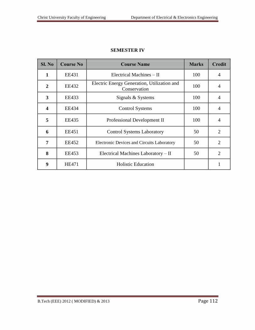
Christ University Faculty of Engineering Department of Electrical & Electronics Engineering
B.Tech (EEE) 2012 ( MODIFIED) & 2013 Page 112
SEMESTER IV
Sl. No Course No Course Name Marks Credit
1 EE431 Electrical Machines – II 100 4
2 EE432 Electric Energy Generation, Utilization and
Conservation 100 4
3 EE433 Signals & Systems 100 4
4 EE434 Control Systems 100 4
5 EE435 Professional Development II 100 4
6 EE451 Control Systems Laboratory 50 2
7 EE452 Electronic Devices and Circuits Laboratory 50 2
8 EE453 Electrical Machines Laboratory – II 50 2
9 HE471 Holistic Education 1

Christ University Faculty of Engineering Department of Electrical & Electronics Engineering
B.Tech (EEE) 2012 ( MODIFIED) & 2013 Page 113
EE431 ELECTRICAL MACHINES - II
AIM
To expose the students to the concepts of synchronous and asynchronous
machines and analyze their performance.
OBJECTIVES
To impart knowledge on
i. Construction and performance of salient and non – salient type
synchronous generators.
ii. Principle of operation and performance of synchronous motor.
iii. Construction, principle of operation and performance of induction
machines.
iv. Starting and speed control of three-phase induction motors.
v. Construction, principle of operation and performance of single phase
induction motors and special machines.
UNIT I: SYNCHRONOUS GENERATOR 9 + 3
Constructional details – Types of rotors – emf equation – Synchronous reactance –
Armature reaction – Voltage regulation – e.m.f, m.m.f, z.p.f and A.S.A methods –
Synchronizing and parallel operation – Synchronizing torque - Change of excitation and
mechanical input – Two reaction theory – Determination of direct and quadrature axis
synchronous reactance using slip test – Operating characteristics - Capability curves.
UNIT II: SYNCHRONOUS MOTOR 8 + 3
Principle of operation – Torque equation – Operation on infinite bus bars - V-curves –
Power input and power developed equations – Starting methods – Current loci for
constant power input, constant excitation and constant power developed.
UNIT III: THREE PHASE INDUCTION MOTOR 12 + 3
Constructional details – Types of rotors – Principle of operation – Slip – Equivalent
circuit – Slip-torque characteristics - Condition for maximum torque – Losses and
efficiency – Load test - No load and blocked rotor tests - Circle diagram – Separation of
no load losses – Double cage rotors – Induction generator – Synchronous induction
motor.
Christ University Faculty of Engineering Department of Electrical & Electronics Engineering
B.Tech (EEE) 2012 ( MODIFIED) & 2013 Page 114
UNIT IV: STARTING AND SPEED CONTROL OF THREE PHASE INDUCTION
MOTOR 7 + 3
Need for starting – Types of starters – Stator resistance and reactance, rotor resistance,
autotransformer and star-delta starters – Speed control – Change of voltage, torque,
number of poles and slip – Cascaded connection – Slip power recovery scheme.
UNIT V: SINGLE PHASE INDUCTION MOTORS AND SPECIAL MACHINES
9 + 3
Constructional details of single phase induction motor – Double revolving field theory
and operation – Equivalent circuit – No load and blocked rotor test – Performance
analysis – Starting methods of single-phase induction motors - Special machines - Shaded
pole induction motor, reluctance motor, repulsion motor, hysteresis motor, stepper motor
and AC series motor.
TEXT BOOKS
1. D.P. Kothari and I.J. Nagrath, ‘Electric Machines’, Tata McGraw Hill Publishing
Company Ltd, 2002.
2. P.S. Bhimbhra, ‘Electrical Machinery’, Khanna Publishers, 2003.
REFERENCE BOOKS
1. A.E. Fitzgerald, Charles Kingsley, Stephen.D.Umans, ‘Electric Machinery’, Tata
McGraw Hill publishing Company Ltd, 2003.
2. J.B. Gupta, ‘Theory and Performance of Electrical Machines’, S.K.Kataria and
Sons, 2002.
3. K. Murugesh Kumar, ‘Electric Machines’, Vikas publishing house Pvt Ltd, 2002.
4. Sheila.C.Haran, ‘Synchronous, Induction and Special Machines’, Scitech
Publications, 2001.
Christ University Faculty of Engineering Department of Electrical & Electronics Engineering
B.Tech (EEE) 2012 ( MODIFIED) & 2013 Page 115
EE432 ELECTRIC ENERGY GENERATION, UTILISATION AND
CONSERVATION
AIM
To expose students to the main aspects of generation, utilization and conservation.
OBJECTIVES
To impart knowledge on
i. Generation of electrical power by conventional and non – conventional
methods.
ii. Electrical energy conservation, energy auditing and power quality.
iii. Principle and design of illumination systems and methods of heating and
welding.
iv. Electric traction systems and their performance.
v. Industrial applications of electric drives.
UNIT I: GENERATION 8 + 3
Generation of electrical power by conventional methods – a brief review – generation
from tidal, wind, MHD, geothermal and solar sources – introduction to the concept of
distributed generation – effect on system operation.
UNIT II: CONSERVATION 10 + 3
Economics of generation – definitions – load curves – number and size of units – cost of
electrical energy – tariff – need for electrical energy conservation – methods – energy
efficient equipment – energy management – energy auditing.
Economics of power factor improvement – design for improvement of power factor using
power capacitors – power quality – effect on conservation.
UNIT III: ILLUMINATION, HEATING AND WELDING 10 + 3
Nature of radiation – definition – laws – photometry – lighting calculations – design of
illumination systems (for residential, industrial, commercial, health care, street lightings,
sports, administrative complexes) - types of lamps - energy efficiency lamps.
Methods of heating, requirement of heating material – design of heating element –
furnaces – welding generator – welding transformer and its characteristics.
Christ University Faculty of Engineering Department of Electrical & Electronics Engineering
B.Tech (EEE) 2012 ( MODIFIED) & 2013 Page 116
UNIT IV: ELECTRIC TRACTION 9 + 3
Introduction – requirements of an ideal traction system – supply systems – mechanics of
train movement – traction motors and control – multiple units – braking – current
collection systems – recent trends in electric traction.
UNIT V: DRIVES AND THEIR INDUSTRIAL APPLICATIONS 8 + 3
Introduction – motor selection and related factors – loads – types – characteristics –
steady state and transient characteristics – load equalization – industrial applications –
modern methods of speed control of industrial drives.
TEXT BOOKS
1. E. Openshaw Taylor, ‘Utilization of Electrical Energy in SI Units’, Orient
Longman Pvt.Ltd, 2003.
2. B.R. Gupta, ‘Generation of Electrical Energy’, Eurasia Publishing House (P) Ltd,
New Delhi, 2003.
REFERENCE BOOKS
1. H. Partab, ‘Art and Science of Utilisation of Electrical Energy’, Dhanpat Rai and
Co, New Delhi, 2004.
2. Gopal.K.Dubey, ‘Fundamentals of Electrical Drives’, Narosa Publishing House,
New Delhi, 2002.
3. C.L. Wadhwa, ‘Generation, Distribution and Utilization of Electrical Energy’,
New Age International Pvt.Ltd, 2003.
4. J.B. Gupta, ‘Utilization of Electric Power and Electric Traction’, S.K.Kataria and
Sons, 2002.
Christ University Faculty of Engineering Department of Electrical & Electronics Engineering
B.Tech (EEE) 2012 ( MODIFIED) & 2013 Page 117
EE433 SIGNALS AND SYSTEMS
AIM
To study and analyze characteristics of continuous, discrete time signals and systems.
OBJECTIVES
To study the properties and representation of continuous and discrete time signals.
To study the sampling process and analysis of discrete systems using z-transforms.
To study the analysis and synthesis of discrete time systems.
UNIT I REPRESENTATION OF SIGNALS AND SYSTEMS 9 + 3
Continuous and discrete time signals: Classification of Signals – Periodic &
Aperiodic, Even & Odd, Energy & Power signals, Deterministic & Random signals,
Transformation in independent variable of signals: time scaling, time shifting, time
reversal. Complex exponential and Sinusoidal signals, Periodicity of continuous and
discrete signals, Basic/Elementary functions: unit impulse, unit step functions, Basic
system properties.
UNIT II LINEAR TIME-INVARIANT CONTINUOUS TIME SYSTEMS9 + 3
Introduction, Convolution Integral, Properties of Linear Time Invariant Systems.
Differential Equations representation of Systems, Solving Differential Equations, Natural
and Forced Response of the system, Block Diagram Representation.
UNIT III Fourier analysis Of Continuous and Discrete Time Signals and Systems
Introduction, Frequency response of LTI systems, Fourier representation of Four Classes
of signals, Fourier series, Fourier Transform, Discrete Time Fourier Series, Discrete
Time Fourier Transform, Properties of Fourier Representations, Continuous time Fourier
Transform and Laplace Transform analysis with examples, convolution in time and
frequency domains.
Christ University Faculty of Engineering Department of Electrical & Electronics Engineering
B.Tech (EEE) 2012 ( MODIFIED) & 2013 Page 118
UNIT IV SAMPLING THEOREM AND z-TRANSFORMS 9 + 3
Representation of continuous time signals by its sample - Sampling theorem –
Reconstruction of a Signal from its samples, aliasing – discrete time processing of
continuous time signals, sampling of band pass signals. Basic principles of z-transform -
z-transform definition – region of convergence – properties of ROC – Properties of z-
transform – Poles and Zeros – inverse z-transform
UNIT V LINEAR TIME-INVARIANT DISCRETE TIME SYSTEMS 9 + 3
Introduction, Convolution sum, Properties of Linear Time Invariant Systems.
Difference Equations representation of Systems, Solving Difference Equations, Natural
and Forced Response of the system, Block Diagram Representation.
L = 45 T = 15 Total = 60
TEXT BOOK
1. Alan V.Oppenheim, Alan S.Willsky with S.Hamid Nawab, Signals & Systems,
2nd edn., Pearson Education, 1997.
REFERENCES
1. Simon Haykin and Barry Van Veen, Signals and Systems, John Wiley, 1999
2. John G.Proakis and Dimitris G.Manolakis, Digital Signal Processing, Principles,
Algorithms and Applications, 3rd edn., PHI, 2000.
3. M.J.Roberts, Signals and Systems Analysis using Transform method and
MATLAB, TMH 2003.
4. K.Lindner, “Signals and Systems”, McGraw Hill International, 1999
5. Moman .H. Hays,” Digital Signal Processing “, Schaum’s outlines, Tata McGraw-
Hill Co Ltd., 2004.
6. Ashok Amhardar, “Analog and Digital Signal Processing”, 2 nd Edition Thomson
2002.
Christ University Faculty of Engineering Department of Electrical & Electronics Engineering
B.Tech (EEE) 2012 ( MODIFIED) & 2013 Page 119
EE434 CONTROL SYSTEMS
AIM
To provide sound knowledge in the basic concepts of linear control theory and design of
control system.
OBJECTIVES
i. To understand the methods of representation of systems and getting their
transfer function models.
ii. To provide adequate knowledge in the time response of systems and
steady state error analysis.
iii. To give basic knowledge is obtaining the open loop and closed–loop
frequency responses of systems.
iv. To understand the concept of stability of control system and methods of
stability analysis.
v. To study the three ways of designing compensation for a control system.
UNIT I: SYSTEMS AND THEIR REPRESENTATION 9 + 3
Basic elements in control systems – Open and closed loop systems – Electrical analogy of
mechanical and thermal systems – Transfer function – Synchros – AC and DC
servomotors – Block diagram reduction techniques – Signal flow graphs.
UNIT II: TIME RESPONSE 9 + 3
Time response – Time domain specifications – Types of test input – I and II order system
response – Error coefficients – Generalized error series – Steady state error – P, PI, PID
modes of feed back control.
UNIT III: FREQUENCY RESPONSE 9 + 3
Frequency response – Bode plot – Polar plot – Constant M an N circles – Nichols chart –
Determination of closed loop response from open loop response – Correlation between
frequency domain and time domain specifications.
UNIT IV: STABILITY OF CONTROL SYSTEM 9 + 3
Characteristics equation – Location of roots in S plane for stability – Routh Hurwitz
criterion – Root locus construction – Effect of pole, zero addition – Gain margin and
phase margin – Nyquist stability criterion.
Christ University Faculty of Engineering Department of Electrical & Electronics Engineering
B.Tech (EEE) 2012 ( MODIFIED) & 2013 Page 120
UNIT V: COMPENSATOR DESIGN 9 + 3
Performance criteria – Lag, lead and lag-lead networks – Compensator design using bode
plots.
TEXT BOOKS
1. K. Ogata, ‘Modern Control Engineering’, 4th edition, Pearson Education, New
Delhi, 2003 / PHI.
2. I.J. Nagrath & M. Gopal, ‘Control Systems Engineering’, New Age International
Publishers, 2003.
REFERENCE BOOKS
1. B.C. Kuo, ‘Automatic Control Systems’, Prentice Hall of India Ltd., New Delhi,
1995.
2. M. Gopal, ‘Control Systems, Principles & Design’, Tata McGraw Hill, New
Delhi, 2002.
1. M.N. Bandyopadhyay, ‘Control Engineering Theory and Practice’, Prentice Hall
of India, 2003.
Christ University Faculty of Engineering Department of Electrical & Electronics Engineering
B.Tech (EEE) 2012 ( MODIFIED) & 2013 Page 121
EE435 PROFESSIONAL DEVELOPMENT – II
AIM
This course is an introduction to the human resources function, industrial relations and
interpersonal relationship. The course outlines the roles and functions of members of the
human resources department, as well as educating others outside human resources, in
how their roles included human resources-related activities.
OBJECTIVES
1. To provide an understanding of the human resources management framework.
2. Offers experiential analysis to understand the challenges of HR Managers in
developing their organizations.
3. Provides insights on how to develop strategies, initiatives and programs to
introduce and sustain competitive HR advantage in organizations.
4. Focuses on management best practices, tools and models to implement an
effective HRM system.
5. Addresses the human capital as a critical role in firm's viability in the knowledge
economy.
PRINCIPLES OF HUMAN RESOURCES MANAGEMENT, INDUSTRIAL
RELATIONS & INTERPERSONAL RELATIONSHIP
MODULE 1 6
HRM- Introduction, meaning, definition, nature and scope of HRM and HRD, evolution
of HRM, Difference between Personnel Management and HRM, features of HRM, HRM
functions, objectives of HRM, policies, procedures and programmes, practices,
Organization of HRM, line and staff responsibility role of personnel manager and HR
manager, qualities of HR, HR Manager as a Strategic partner, factors fluencing HRM,
Opportunities and Challenges in Human Resource Management.
MODULE 2 7
Job design: definition, approaches, job design options;
Job analysis: definition, process, benefits of job analysis
HR planning: introduction, objectives of HRP, linkage of HRP to other plans, definition and
need for HRP, benefits of HRP, factors affecting HRP, process, problems and limitations of HRP
MODULE 3 6
Recruitment: definition, objectives, subsystems, factors affecting recruitment policy,
centralized and decentralized recruitment, recruitment Organisation, recruitment sources,
recruitment techniques, recruitment process, cost benefit analysis of recruitment sources.
Christ University Faculty of Engineering Department of Electrical & Electronics Engineering
B.Tech (EEE) 2012 ( MODIFIED) & 2013 Page 122
MODULE 4 6
Selection, Placement and Induction: meaning, definition of selection, essentials of
selection procedure, significance of selection process and organizational relationship,
selection procedure, various types of tests (aptitude, achievement, situational, interest,
and personality), different types of interviews and interview process, means to make
interview effective, medical exams, reference checks, final decision, employment,
placement and induction.
MODULE 5 5
Performance management: Introduction, meaning, need, purpose, objectives, contents
of PAS, appraisers and different methods of appraisal, uses of performance appraisal,
limitations and problems of performance appraisal, 360 degree Appraisal, post appraisal
feedback.
MODULE 6 13
Human Resource Development: Introduction, definition, concepts, activities
Training and development: meaning of T & D, importance of training, benefits of
training, need and objectives, assessment of training needs, areas of training, training
methods, on-the job and off-the-job training, advantages of training, training procedures
and final evaluation.
Employee mobility:
Internal mobility: Introduction, meaning, different types
Promotion: meaning, purpose, bases of merit, seniority, merit cum seniority, benefits,
problems, promotion policy.
Transfer: meaning, purpose, types, reasons, benefits,
Demotion: meaning, need for demotion policy.
Career planning and Development: meaning, need, career development actions.
External mobility: Introduction, meaning, types.
Absenteeism: Meaning, types, causes, calculation, minimizing absenteeism.
Employee attrition: meaning, reasons, calculation of attrition rate, retention strategies,
managing separations and right sizing-voluntary and involuntary separations.
MODULE 7 8
Compensation & Benefits Administration: Compensation Management: Introduction,
definition, need for sound salary administration, objectives, factors affecting wages/
salary levels, job evaluation, wage salary survey, salary structure, salary fixation,
incentives, profit sharing, bonus concepts, ESOPs, pay for performance, Benefits
administration, employee welfare and working conditions-statutory and voluntary
measures.
MODULE 8 9
Christ University Faculty of Engineering Department of Electrical & Electronics Engineering
B.Tech (EEE) 2012 ( MODIFIED) & 2013 Page 123
Industrial peace and harmony: Discipline maintenance, Grievance Handling, Workers
participation in management, maintaining good human and industrial relations, benefits
accrued by the organization due to the development of congenial environment.
Group and Co-Operative Processes: Group – behavior, development, structure and
processes. Teams – types and contemporary issues, individual – personality, learning,
perception, values, attitudes and job satisfaction. Assertiveness – communication styles,
self expression, social boldness. Emotional intelligence. Transactional analysis – ego
states, life positions, transactions, stroking, Motivation, Leadership, Conflict and
Negotiation.
RECOMMENDED BOOKS:
1. Managing Human Resources – Bohlander et all – Cengage Learning 13 Ed., 2004.
2. Human Resource Management, Text & Cases – VSP Rao, Excel Books, 2005
3. Human Resource Management – Text & Cases – K. Ashwatappa; 5th Edition, TMH.
4. Human Resource Management - Cynthia Fisher, Shaw – Wiley / Biztantra, 5/e, 2005
5. Human Resource Management – Gary Dessler, Person Publications, 10th Edition
6. Human Resource Management -Biswajeet Patnayak - PHI 3IE, 2005
Christ University Faculty of Engineering Department of Electrical & Electronics Engineering
B.Tech (EEE) 2012 ( MODIFIED) & 2013 Page 124
EE451 CONTROL SYSTEMS LABORATORY
AIM
To provide a platform for understanding the basic concepts of linear control theory
and its application to practical systems.
List of Experiments
1. Determination of transfer function parameters of a DC servo motor.
2. Determination of transfer function parameters of AC servo motor.
3. Analog simulation of type-0 and type-1 system.
4. Digital simulation of linear systems.
5. Digital simulation of non-linear systems.
6. Design and implementation of compensators.
7. Design of P, PI and PID controllers.
8. Stability analysis of linear systems.
9. Closed loop control system.
10. Study of synchros.
Detailed Syllabus
1. Determination of Transfer Function Parameters of A DC Servo Motor
Aim
To derive the transfer function of the given D.C Servomotor and
experimentally determine the transfer function parameters
Exercise
1. Derive the transfer function from basic principles for a separately excited DC
motor.
2. Determine the armature and field parameters by conducting suitable
experiments.
3. Determine the mechanical parameter by conducting suitable experiments.
4. Plot the frequency response.
Christ University Faculty of Engineering Department of Electrical & Electronics Engineering
B.Tech (EEE) 2012 ( MODIFIED) & 2013 Page 125
Equipment
1. DC servo motor : minimum of 100w – field
separately excited – loading facility
– variable voltage source - 1 No
2. Tachometer : 1 No
3. Multimeter : 2 Nos
4. Stop watch : 1 No
2. Determination Of Transfer Function Parameters Of Ac Servo Motor
Aim
To derive the transfer function of the given A.C Servo Motor and experimentally
determine the transfer function parameters
Exercise
1. Derive the transfer function of the AC Servo Motor from basic principles.
2. Obtain the D.C gain by operating at rated speed.
3. Determine the time constant (mechanical)
4. Plot the frequency response
Equipment
1. AC Servo Motor : Minimum of 100w – necessary sources for
main winding and control winding – 1 No
2. Tachometer : 1 No
3. Stopwatch : 1 No
4. Voltmeter : 1 No
3. Analog Simulation Of Type-0 And Type-1 System
Aim
To simulate the time response characteristics of I order and II order, type 0 and
type-1 systems.
Exercise
1. Obtain the time response characteristics of type – 0 and type-1, I order and II
order systems mathematically.
2. Simulate practically the time response characteristics using analog rigged up
modules.
Christ University Faculty of Engineering Department of Electrical & Electronics Engineering
B.Tech (EEE) 2012 ( MODIFIED) & 2013 Page 126
3. Identify the real time system with similar characteristics.
Equipment
i. Rigged up models of type-0 and type-1 system using analog components.
ii. Variable frequency square wave generator and a normal CRO - 1 No
(or)
DC source and storage Oscilloscope - 1 No
4. Digital Simulation Of Linear Systems
Aim
To digitally simulate the time response characteristics of higher-order
MIMO linear systems using state – variable formulation
Exercise
1. Obtain the state variable formulation of the given higher–order MIMO
systems.
2. Write a program or build the block diagram model using the given
software.
3. Obtain the impulse, step and sinusoidal response characteristics.
4. Identify real time systems with similar characteristics.
Equipment
1. System with MATLAB / MATHCAD (or) equivalent software -
minimum 3 user license.
5. Digital Simulation Of Non-Linear Systems
Aim
To digitally simulate the time response characteristics of a linear system
with simple non-linearities like saturation and dead zone.
Exercise
1. Obtain the time response characteristics of some simple linear systems
without non - linearity for step and sinusoidal inputs.
2. Repeat the time response characteristics in the presence of non-linearity
3. Discuss the effect of non-linearity
Christ University Faculty of Engineering Department of Electrical & Electronics Engineering
B.Tech (EEE) 2012 ( MODIFIED) & 2013 Page 127
Equipment
1. System with MATLAB / MATHCAD (or) other equivalent software - 3
user license.
6. Design And Implementation Of Compensators
Aim
To design and implement suitable compensator for a given linear system
to improve the performance.
Exercise
1. Study the time response characteristics of the given linear system without
compensator.
2. Design a suitable compensator to improve the performance.
3. Implement the compensator using variable R,L and C boxes to the linear
system and visually observe the performance improvement.
Equipment
1. Analog Rigged up modules of a linear system (For closed loop operation)
2. Variable R, L and C boxes – each - 2 Nos
3. Square wave generator and a CRO - 1 No (or)
i. DC voltage source and storage oscilloscope - 1 No
7. Design Of P, Pi And Pid Controllers
Aim
To design P, PI and PID controllers for first order systems and implement
them practically.
Exercise
1. Study the time response behaviour of first order system without controller
2. Design a P/PI/PID controller to improve the performance
3. Implement the controller using variable R,L and C boxes to linear system
and visually observe the performance improvement.
Equipment
1. Rigged up module of P, PI and PID controller using analog components
Rigged up module of I order system (with loop closing facility)
Variable R, L and C boxes – 2 each
1No
Christ University Faculty of Engineering Department of Electrical & Electronics Engineering
B.Tech (EEE) 2012 ( MODIFIED) & 2013 Page 128
(or)
Process control trainer with all the above features
2. CRO and a square wave generator – 1 No
(or)
DC source and a storage oscilloscope – 1 No
8. Stability Analysis Of Linear Systems
Aim
To analyse the stability of linear systems using Bode / Root locus / Nyquist plot
Exercise
1. Write a program to obtain the Bode plot / Root locus / Nyquist plot for the
given system
2. Access the stability of the given system using the plots obtained
3. Compare the usage of various plots in assessing stability
Equipment
1. System with MATLAB / MATHCAD / equivalent software - 3 user license
9. CLOSED LOOP CONTROL SYSTEM
Aim
To study the behaviour of closed loop control system through practical
experimentation.
Exercise
1. Obtain the block diagram representation of the given closed loop control
system.
2. Conduct experiments to study the open loop time response behaviour for
various set points.
3. Conduct experiments to study the closed loop time response behaviour for
various set points.
4. Repeat 3 with a second type of controller and discuss the results.
Equipment
1. A complete closed loop position / speed / Temperature or equivalent system
with two detachable controller units.
2. CRO
Christ University Faculty of Engineering Department of Electrical & Electronics Engineering
B.Tech (EEE) 2012 ( MODIFIED) & 2013 Page 129
10. Study of Synchros
Aim
To study the characteristics of synchros as error detector
Exercise
1. Obtain the input-output characteristics of synchro transmitter by giving
excitation to the rotor winding and measuring the output voltages across
S1 – S2, S2-S3 and S3-S1 of stator windings for different rotor positions
2. Obtain the characteristics of synchro as angular displacement sensor and
plot voltage Vs angle characteristics
3. Obtain the characteristic of synchro used as remote angle displacement of
receiver tracks that of transmitter
Equipment
1. Synchronous (transmitter and Receiver) : 1 set
2. Rheostat : 1 No
3. Multimeter : 1 No
Christ University Faculty of Engineering Department of Electrical & Electronics Engineering
B.Tech (EEE) 2012 ( MODIFIED) & 2013 Page 130
EE452 ELECTRONIC DEVICES AND CIRCUITS LABORATORY
AIM
To study the characteristics and to determine the device parameters of various
solid-state devices.
1. Static Characteristics of transistor under CE, CB, CC and determination of
hybrid parameters.
2. Static characteristics and parameter determination of JFET.
3. Static characteristics of semiconductor diode, zener diode and study of simple
voltage regulator circuits.
4. Static characteristics of UJT and its application as a relaxation oscillator.
5. Photodiode, Phototransistor characteristics and study of light activated relay
circuit.
6. Static characteristics of Thermistors.
7. Single phase half wave and full wave rectifiers with inductive and capacitive
filters.
8. Phase shift oscillators and Wien bridge oscillators.
9. Frequency response of common emitter amplifiers.
10. Differential amplifiers using FET.
Detailed Syllabus
1. Static Characteristics of transistor under CE, CB, CC and determination of
hybrid parameters
Aim
To determine the static characteristics of transistor under CE, CB, CC mode.
Exercise
a. Plot the BJT CE, CB and CC input and output characteristics.
b. Determine the h-parameters hi, ho, hr and hf for CE, CB and CC
characteristics from I/P and O/P characteristics.
Christ University Faculty of Engineering Department of Electrical & Electronics Engineering
B.Tech (EEE) 2012 ( MODIFIED) & 2013 Page 131
2. Static characteristics and parameter determination of JFET
Aim
To determine the static characteristics of JFET
Exercise
1. Plot the JFET drain characteristics from the results obtained
2. Plot the JFET transfer characteristics from the results obtained.
3. From the drain characteristics for VGS = 0 determine the value of the rD and
YOS parameters.
4. From the transfer characteristic, determine the values of the Yfs parameters at
VGS =-1 V and VGS = - 4V.
5. Draw horizontal and vertical scales on the drain characteristics plotted by the
XY recorder. Identify each characteristic according to the VGS level. Also,
print the JFET type number on the characteristics.
3. Static characteristics of semiconductor diode, zener diode and study of
simple voltage regulator circuits
Aim
1. To determine the static characteristics of semiconductor diode and zener diode
2. To study the simple voltage regulator circuits as Op-amp voltage regulator,
source effect and load effect measurement, use of current limiter.
Exercise
Semiconductor diode
1. Plot the forward characteristic of the low – current diode and rectifier diode
from the results obtained.
2. From the forward characteristics, determine the approximate forward voltage
drop and dc forward resistance for D2 and for D2. Also estimate the ac
resistance for each diode.
3. Comment on the results of reverse biased diode current measurements.
Zener diode
a. Plot a graph showing the Zener diode reverse characteristics.
b. From the Zener diode reverse characteristics determine the reverse voltage at
IZ = 20 mA. Also determine the dynamic impedance for the device.
c. Calculate the line regulation, load regulation and ripple reduction factor
produced by the Zener diode regulator.
Christ University Faculty of Engineering Department of Electrical & Electronics Engineering
B.Tech (EEE) 2012 ( MODIFIED) & 2013 Page 132
Voltage regulator
1. Analyze the voltage regulator circuit for ripple reduction, source effect and
load effect. Compare the calculated and measured circuit performance.
2. Plot the regulator current limiting characteristics. Analyze the two current
limiter circuits and compare the calculated and measured circuit
performances.
4. Static characteristics of UJT and its application as a relaxation oscillator
Aim
To determine the static characteristics of UJT.
Exercise
1. Plot the UJT characteristics from the results obtained.
2. Calculate the intrinsic stand – off ratio from the results obtained.
3. Compare the calculated value with the specified value for the UJT.
4. Discuss the waveforms obtained for the UJT relaxation oscillator investigated.
Compare the operating frequency with that calculated frequency.
5. Photodiode, Phototransistor characteristics and study of light activated relay
circuit
Aim
1. To draw the characteristics of photodiode, phototransistor.
2. To study the light activated relay circuit.
Exercise
Photodiode
1. Plot the photodiode reverse current upon different level of illumination.
2. Draw the dc load line for the circuit and determine the diode currents and
voltages at different level of illumination.
Phototransistor
1. Draw the output characteristics IC / VCE of a phototransistor and determine the
output voltage at different illumination levels.
2. Bias Phototransistor as a switch. Illuminate the phototransistor to activate a
relay.
6. Static characteristics of Thermistors
Aim
To determine the static characteristics of thermistors.
Christ University Faculty of Engineering Department of Electrical & Electronics Engineering
B.Tech (EEE) 2012 ( MODIFIED) & 2013 Page 133
Exercise
1. Draw the resistance / temperature characteristic of a thermistor and determine
the resistance value for variations in temperature.
2. Draw the static voltage / current characteristics of a thermistor and determine
whether device resistance remains constant until power dissipation is large
enough to produce self-heating.
3. Use the thermistor as a temperature-compensating device by increasing the
resistance with increasing temperature.
7. Single phase half wave and full wave rectifiers with inductive and capacitive
filters
Aim
To construct half wave and full wave rectifiers and to draw their input and output
waveforms.
Exercise
Plot the input and output waveforms and explain the difference between
the two.
Explain the effect of open – circuiting of any one diode.
Measure the PIV of two-diode full wave rectifier to the bridge rectifier.
Calculate the ripple factor of output waveform of inductive and capacitive
filter and compare it with measured practical values.
8. Phase shift oscillators and Wien bridge oscillators
Aim
To construct the phase shift oscillator and Wien bridge oscillators and to draw its
output waveforms.
Exercise
1. Discuss the phase shift oscillator and Wien bridge oscillator output waveforms
obtained from the experiment. Analyze the circuits and compare the
calculated and measured frequencies.
2. Change the capacitor values and discuss the results.
3. Analyze the diode amplitude stabilization circuit for the Wien bridge
oscillator and compare the calculated output amplitude to that of the measured
values.
9. Frequency response of common emitter amplifiers
Aim
To determine the frequency response of common emitter amplifiers.
Christ University Faculty of Engineering Department of Electrical & Electronics Engineering
B.Tech (EEE) 2012 ( MODIFIED) & 2013 Page 134
Exercise
1. For different values of cut – off frequencies determine suitable values of
resistors and capacitors for common emitter amplifiers.
2. Plot the frequency response and determine 3dB bandwidth.
10. Differential amplifiers using FET
Aim
To analyse the characteristics of differential amplifier circuit using FET
Exercise
1. Construct the circuit and
a. Determine differential gain Ad
b. Determine common mode gain Ac
c. Determine the CMRR = Ad / Ac
2. Construct the circuit using common source configuration. Measure i/p – o/p
impedance of the circuit.
3. Try the same as common drain circuit (source follower) and check for VDD =
25V
Christ University Faculty of Engineering Department of Electrical & Electronics Engineering
B.Tech (EEE) 2012 ( MODIFIED) & 2013 Page 135
EE453 ELECTRICAL MACHINES LABORATORY – II
AIM
To expose the students to the operation of synchronous machines and induction
motors and give them experimental skill.
1. Regulation of three phase alternator by emf and mmf methods
2. Regulation of three phase alternator by ZPF and ASA methods
3. Regulation of three phase salient pole alternator by slip test
4. Measurements of negative sequence and zero sequence impedance of
alternators.
5. V and Inverted V curves of Three Phase Synchronous Motor.
6. Load test on three-phase induction motor.
7. No load and blocked rotor test on three-phase induction motor.
8. Separation of No-load losses of three-phase induction motor.
9. Load test on single-phase induction motor
10. No load and blocked rotor test on single-phase induction motor.
Detailed Syllabus
1. Regulation of three phase alternator by EMF and MMF methods
Aim
To predetermine the voltage regulation of given three phase alternator by emf and
mmf methods.
Exercise
1. Obtain the open circuit and short circuit characteristics of a three phase
alternator.
2. Calculate synchronous impedance from the open circuit characteristics and
short circuit characteristics.
3. Predetermine the full load regulation at different power factor by EMF and
MMF methods and draw the graph between regulation Vs Power factor.
4. Draw the phasor diagram for EMF and MMF method.
2. Regulation of three-phase alternator by ZPF and ASA methods
Aim
To predetermine the voltage regulation of given three phase alternator by ZPF and
ASA method.
Christ University Faculty of Engineering Department of Electrical & Electronics Engineering
B.Tech (EEE) 2012 ( MODIFIED) & 2013 Page 136
Exercise
a. Obtain the open circuit, short circuit and zero power factor lagging load
characteristics.
b. To construct the Potier triangle.
c. Draw the phasor diagram for ZPF and ASA method.
d. Predetermine the full load regulation at different power factor by ZPF and
ASA methods
3. Regulation of three-phase salient pole alternator by slip test
Aim
To predetermine the voltage regulation of a given three phase salient pole alternator.
Exercise
1. Determine the Xd and Xq of the salient pole alternator.
2. To draw the phasor diagram.
3. To predetermine full load regulation at different power factor.
4. Measurements of negative sequence and zero sequence impedances of
alternators
Aim
To determine the positive, negative and zero sequence impedance of alternator.
Exercise
1. Determine the positive and negative sequence impedance by suitable test.
2. Determine the zero sequence impedance by suitable test.
5. V and Inverted V Curves of Three Phase Synchronous Motor
Aim
To determine the V and inverted V curves of three phase synchronous motor.
Exercise
1. Synchronize the synchronous motor to the bus bar.
2. Obtain the V and inverted V curves of the synchronous motor at no load,
constant input and constant output.
Christ University Faculty of Engineering Department of Electrical & Electronics Engineering
B.Tech (EEE) 2012 ( MODIFIED) & 2013 Page 137
6. Load Test On Three Phase Induction Motor
Aim
To obtain the load characteristics of three phase induction motor.
Exercise
1. Conduct the load test on a given three-phase induction motor and draw the
following curves.
1. Output Vs % η
2. Output Vs Speed
3. Output Vs Line current
4. Output Vs Slip
5. Output Vs Power factor
6. T Vs N (on separate graph sheet)
7. No Load And Blocked Rotor Test On Three-Phase Induction Motor
Aim
To conduct no load and blocked rotor test and to draw the equivalent
circuit and predetermine the performance.
Exercise
1. Determine the equivalent circuit parameters.
2. Draw the circle diagram and predetermine the efficiency, torque, power
factor, slip and line current for three load condition.
3. Predetermine the performance characteristics using the equivalent circuit for
three load condition.
8. Separation Of No-Load Losses Of Three Phase Induction Motor
Aim
To separate the constant loss of a three phase induction motor and separate into
iron loss and mechanical losses.
Exercise
1. Draw the curve voltage Vs Input and separate the constant losses into iron and
mechanical loss.
2. Study the star / delta and autotransformer starters internal circuitry
arrangements.
9. Load Test On Single Phase Induction Motor
Aim
To obtain the load characteristics of single phase motor by load test.
Christ University Faculty of Engineering Department of Electrical & Electronics Engineering
B.Tech (EEE) 2012 ( MODIFIED) & 2013 Page 138
Exercise
1. Conduct the load test on given single-phase induction motor and draw the
following curves.
a. Output Vs % η
b. Output Vs Speed
c. Output Vs Line current IB
d. Output Vs Slip
e. Output Vs Power factor
10. No Load And Blocked Rotor Test On Single Phase Induction Motor
Aim
To conduct no load and blocked rotor test on single phase induction motor and
predetermine the performance using equivalent circuit.
Exercise
1. Determine the equivalent circuit parameters from no load and blocked rotor
test.
2. To predetermine the efficiency, torque, power factor and line current using the
equivalent circuit parameters.

Christ University Faculty of Engineering Department of Electrical & Electronics Engineering
B.Tech (EEE) 2012 ( MODIFIED) & 2013 Page 139
(THIRD YEAR)
SEMESTER V
Sl. No Course No Course Name Marks Credit
1 EE531 Power System Analysis 100 4
2 EE532 Digital Signal Processing 100 4
3 EE533 Microprocessor and its applications 100 4
4 EE534 Power Electronics 100 4
5 EE535 Transmission & Distribution 100 4
6 EE536 Object oriented Programming 100 4
7 EE551 Power Electronics & Drives Laboratory 50 2
8 EE552 Digital Signal Processing Laboratory 50 2
Christ University Faculty of Engineering Department of Electrical & Electronics Engineering
B.Tech (EEE) 2012 ( MODIFIED) & 2013 Page 140
EE531 POWER SYSTEM ANALYSIS
AIM
To become familiar with different aspects of modeling of components and system
and different methods of analysis of power system planning and operation.
OBJECTIVES
i. To model steady-state operation of large-scale power systems and o solve the
power flow problems using efficient numerical methods suitable for computer
simulation.
ii. To model and analyse power systems under abnormal (fault) conditions.
iii. To model and analyse the dynamics of power system for small-signal and large
signal disturbances and o design the systems for enhancing stability.
UNIT I: THE POWER SYSTEM – AN OVERVIEW AND MODELLING 9 + 3
Modern Power System - Basic Components of a power system - Per Phase Analysis
Generator model - Transformer model - line model. The per unit system -Change of base.
UNIT II: POWER FLOW ANALYSIS 9 + 3
Introduction - Bus Classification - Bus admittance matrix - Solution of non-linear
Algebraic equations - Gauss seidal method - Newon raphson method - Fast decoupled
method - Flow charts and comparison of the three methods.
UNIT III: FAULT ANALYSIS-BALANCED FAULT 9 + 3
Introduction – Balanced three phase fault – short circuit capacity – systematic fault
analysis using bus impedance matrix – algorithm for formation of he bus impedance
matrix.
UNIT IV: FAULT ANALYSIS – SYMMETRICAL COMPONENTS AND
UNBALANCED FAULT 9 + 3
Introduction – Fundamentals of symmetrical components – sequence impedances –
sequence networks – single line to ground fault – line fault - Double line to ground fault –
Unbalanced fault analysis using bus impedance matrix.
UNIT V: POWER SYSTEM STABILITY 9 + 3
Christ University Faculty of Engineering Department of Electrical & Electronics Engineering
B.Tech (EEE) 2012 ( MODIFIED) & 2013 Page 141
Basic concepts and definitions – Rotor angle stability – Voltage stability – Mid Term and
Long Term stability – Classification of stability – An elementary view of transient
stability – Equal area criterion – Reponses to a short circuit fault- factors influencing
transient stability – Numerical integration methods – Euler method – modified Euler
method – Runge – Kutta methods.
TEXT BOOKS:
1. Hadi Saadat “ Power system analysis”, Tata McGraw Hill Publishing
Company, New Delhi, 2002 (Unit I, II, III, IV)
2. P.Kundur, “Power System Stability and Control”, Tata McGraw Hill
Publishing Company, New Delhi, 1994 (Unit V)
REFERENCE BOOKS:
1. I.J.Nagrath and D.P.Kothari, ‘Modern Power System Analysis’, Tata
McGraw-Hill publishing company, New Delhi, 1990.
2. M.A. Pai, ‘Computer Techniques in power system Analysis’, Tata McGraw –
Hill publishing company, New Delhi, 2003.
Christ University Faculty of Engineering Department of Electrical & Electronics Engineering
B.Tech (EEE) 2012 ( MODIFIED) & 2013 Page 142
EE532 DIGITAL SIGNAL PROCESSING
AIM
To study the signal processing methods and processors.
OBJECTIVES
To study DFT and its computation
To study the design techniques for digital filters
To study the finite word length effects in signal processing
To study the non-parametric methods of power spectrum estimations
To study the fundamentals of digital signal processors.
UNIT I SIGNALS AND SYSTEMS 9 + 3
Classification of signals- Continuous time and discrete time signals, Signal Energy and
Power, Periodic signals, Even and Odd signals, Classification of systems-Continuous
time and Discrete time systems, Basic system properties, Linear time invariant systems,
Convolution Sum, Properties of LTI systems.
UNIT II FOURIER SERIES AND FOURIER TRANSFORM 9 + 3
Fourier series representation of periodic signals, properties, Discrete Time Fourier
Transform abd its properties, DFT – Efficient computation of DFT, Properties of DFT –
FFT algorithms – Radix-2 FFT algorithms – Decimation in Time – Decimation in
Frequency algorithms, Inverse DFT.
Christ University Faculty of Engineering Department of Electrical & Electronics Engineering
B.Tech (EEE) 2012 ( MODIFIED) & 2013 Page 143
UNIT III FIR FILTER DESIGN 9 + 3
Amplitude and phase responses of FIR filters – Linear phase filters – Windowing
techniques for design of Linear phase FIR filters – Rectangular, Hamming, Hanning,
Kaiser windows – frequency sampling techniques – Structure for FIR filters.
UNIT IV IIR FILTER DESIGN 9 + 3
IIR Filters –Magnitude response, Phase response, Analog filter design-Butterworth and
Chebyshev approximations, Digital design using Bilinear and impulse invariant
transformation, Warping, Prewarping, Frequency transformation, Structure for IIR
filters.
UNIT V 9 + 3
FINITE WORD LENGTH EFFECTS : Quantization noise –quantization noise power
– Fixed point and binary floating point number representation – comparison – over flow
error – truncation error – co-efficient quantization error - limit cycle.
DIGITAL SIGNAL PROCESSORS
Introduction to DSP architecture – Harvard architecture - Dedicated MAC unit - Multiple
ALUs, Advanced addressing modes, Pipelining.
TEXT BOOKS
1. John G Proakis, Dimtris G Manolakis, Digital Signal Processing Principles,
Algorithms and Application, PHI, 3rd Edition, 2000,
2. B.Venkataramani & M. Bhaskar, Digital Signal Processor Architecture,
Programming and Application, TMH 2002.
3. S.K.Mitra, “Digital Signal Processing- A Computer based approach”, Tata
McGraw-Hill, 1998, New Delhi.
REFERENCES
1. Alan V Oppenheim, Ronald W Schafer, John R Back, Discrete Time Signal
Processing, PHI, 2nd Edition 2000,
Christ University Faculty of Engineering Department of Electrical & Electronics Engineering
B.Tech (EEE) 2012 ( MODIFIED) & 2013 Page 144
2. Avtar singh, S.Srinivasan DSP Implementation using DSP microprocessor with
Examples from TMS32C54XX -Thamson / Brooks cole Publishers, 2003
3. S.Salivahanan, A.Vallavaraj, Gnanapriya, Digital Signal Processing, McGraw-
Hill / TMH, 2000
4. Johny R.Johnson :Introduction to Digital Signal Processing

Christ University Faculty of Engineering Department of Electrical & Electronics Engineering
B.Tech (EEE) 2012 ( MODIFIED) & 2013 Page 145
EE533 MICROPROCESSORS AND ITS APPLICATIONS
AIM
To learn the architecture programming and interfacing of microprocessors.
OBJECTIVES
To introduce the architecture and programming of 8086 microprocessor.
To introduce the interfacing of peripheral devices with 8086
microprocessor.
To introduce the architecture and programming of 80286, 80386 and
80486 microprocessor.
UNIT I 8086 MICROPROCESSOR
Intel 8086 Microprocessor - Internal architecture – Block diagram – Minimum and
maximum mode operation – Interrupt and Interrupt applications – DMA data transfer –
8086 memory organization – even and odd memory banks – segment registers - logical
and physical address – advantages and disadvantages of physical memory.
UNIT II 8086 MICROPROCESSOR I/O INTERFACING
Intel 8086 microprocessor – Architecture – Instruction set and assembler
directives – Addressing modes – Assembly language programming- Memory Interfacing
and I/O interfacing - Parallel communication interface – Serial communication interface
– Timer – Keyboard /display controller – Interrupt controller – DMA controller –
Programming and applications.
UNIT III 80286 MICROPROCESSOR
Intel 80286 Microprocessor - 80286 Architecture, system connection – Real address
mode operation – Protected mode operation
UNIT IV 80386 MICROPROCESSOR
Intel 80386 Microprocessor - 80386 Architecture and system connection – Real operating
mode – 386 protected mode operation – segmentation and virtual memory – segment
privilege levels and protection – call gates – I/O privilege levels – Interrupts and
exception handling – task switching – paging mode – 80386 virtual 86 mode operation.
UNIT V 80486 MICROPROCESSOR
Christ University Faculty of Engineering Department of Electrical & Electronics Engineering
B.Tech (EEE) 2012 ( MODIFIED) & 2013 Page 146
Advanced Intel Microprocessors - 80486 – Processor model – Reduced Instruction cycle
– five stage instruction pipe line – Integrated coprocessor – On board cache – Burst Bus
mode. Pentium – super scalar architecture – u-v pipe line – branch prediction logic –
cache structure – BIST (built in self test) – Introduction to MMX technology.
References
1. Ramesh S. Gaonkar, “Microprocessor - Architecture, Programming and
Applications with the 8085”, Penram International publishing private limited,
fifth edition.
2. A.K. Ray & K. M. Bhurchandi, “Advanced Microprocessors and peripherals-
Architectures, Programming and Interfacing”, Tata McGraw Hill, 2002 reprint.
3. Barry B. Brey, “The Intel Microprocessors” Pearson Education India., 8th Edition
4. Douglous V. Hall “Microprocessor and Interfacing” Tata McGraw Hill, 2006
revised, 2003.
5. Gibson, “Microprocessor and Interfacing” Tata McGraw Hill, II edition
Christ University Faculty of Engineering Department of Electrical & Electronics Engineering
B.Tech (EEE) 2012 ( MODIFIED) & 2013 Page 147
EE534 POWER ELECTRONICS
AIM
To introduce the application of electronic devices for conversion, control and
conditioning of electric power.
OBJECTIVES
i. To get an overview of different types of power semi-conductor devices and their
switching characteristics.
ii. To understand the operation, characteristics and performance parameters of
controlled rectifiers.
iii. To study the operation, switching techniques and basic topologics of DC-DC
switching regulators.
iv. To learn the different modulation techniques of pulse width modulated inverters
and to understand the harmonic reduction methods.
v. To know the practical application for power electronics converters in conditioning
the power supply.
UNIT I: POWER SEMI-CONDUCTOR DEVICES 9 + 3
Structure, operation and characteristics of SCR, TRIAC, power transistor, MOSFET and
IGBT. Driver and snubber circuits for MOSFET - Turn-on and turn-off characteristics
and switching losses.
UNIT II: PHASE-CONTROLLED CONVERTERS 9 + 3
2-pulse, 3-pulse and 6-pulse converters – Inverter operation of fully controlled converter
- Effect of source inductance - Distortion and displacement factor – Ripple factor - Single
phase AC voltage controllers.
UNIT III: DC TO DC CONVERTERS 9 + 3
Step-down and step-up choppers - Time ratio control and current limit control -
Switching mode regulators: Buck, boost, buck-boost and cuk converter - Resonant
switching based SMPS.
UNIT IV: INVERTERS 9 + 3
Single phase and three phase (both 1200 mode and 1800 mode) inverters - PWM
techniques: Sinusoidal PWM, modified sinusoidal PWM and multiple PWM - Voltage
and harmonic control - Series resonant inverter - Current source inverters.
UNIT V: APPLICATIONS 9 + 3
Uninterrupted power supply topologies - Flexible AC transmission systems - Shunt and
series static VAR compensator - Unified power flow controller- HVDC Transmission.

Christ University Faculty of Engineering Department of Electrical & Electronics Engineering
B.Tech (EEE) 2012 ( MODIFIED) & 2013 Page 148
TEXT BOOKS
1. Muhammad H. Rashid, ‘Power Electronics: Circuits, Devices and Applications’,
Pearson Education, Third edition, 2004 / PHI.
2. Ned Mohan, Tore.M.Undeland, William.P.Robbins, ‘Power Electronics:
Converters, Applications and Design’, John Wiley and sons, third edition, 2003.
REFERENCE BOOKS
1. Cyril.W.Lander, ‘Power Electronics’, McGraw Hill International, Third edition,
1993.
2. Bimal K. Bose, ‘Modern Power Electronics and AC Drives’, Pearson Education,
2003.
3. Mr. Jaganathan, ‘Introduction to Power Electronics’, Prentice Hall of India, 2004.
Christ University Faculty of Engineering Department of Electrical & Electronics Engineering
B.Tech (EEE) 2012 ( MODIFIED) & 2013 Page 149
EE535 TRANSMISSION AND DISTRIBUTION
AIM
To become familiar with the function of different components used in
Transmission and
Distribution levels of power systems and modelling of these components.
OBJECTIVES
i. To develop expression for computation of fundamental parameters of lines.
ii. To categorize the lines into different classes and develop equivalent circuits
for these classes.
iii. To analyse the voltage distribution in insulator strings and cables and methods
to improve the same.
UNIT I: INTRODUCTION 9 + 3
Structure of electric power system: Various levels such as generation, transmission and
distribution; HVDC and EHV AC transmission: comparison of economics of
transmission, technical performance and reliability, application of HVDC transmission
system. FACTS (qualitative treatment only): TCSC, SVC, STATCOM, UPFC.
UNIT II: TRANSMISSION LINE PARAMETERS 9 + 3
Parameters of single and three phase transmission lines with single and double circuits:
Resistance, inductance and capacitance of solid, stranded and bundled conductors:
Symmetrical and unsymmetrical spacing and transposition; application of self and mutual
GMD; skin and proximity effects; interference with neighbouring communication
circuits. Typical configuration, conductor types and electrical parameters of 400, 220,
110, 66 and 33 kV lines.
UNIT III: Modeling and Performance Of Transmission Lines 9 + 3
Classification of lines: Short line, medium line and long line; equivalent circuits,
attenuation constant, phase constant, surge impedance; transmission efficiency and
voltage regulation; real and reactive power flow in lines: Power-angle diagram; surge-
impedance loading, loadability limits based on thermal loading, angle and voltage
stability considerations; shunt and series compensation; Ferranti effect and corona loss.
UNIT IV: INSULATORS AND CABLES 9 + 3
Insulators: Types, voltage distribution in insulator string and grading, improvement of
string efficiency. Underground cables: Constructional features of LT and HT cables,
capacitance, dielectric stress and grading, thermal characteristics.
UNIT V: SUBSTATION, GROUNDING SYSTEM AND DISTRIBUTION SYSTEM 9 + 3
Christ University Faculty of Engineering Department of Electrical & Electronics Engineering
B.Tech (EEE) 2012 ( MODIFIED) & 2013 Page 150
Types of substations; bus-bar arrangements; substation bus schemes: single bus scheme,
double bus with double breaker, double bus with single breaker, main and transfer bus,
ring bus, breaker-and-a-half with two main buses, double bus-bar with bypass isolators.
Resistance of grounding systems: Resistance of driven rods, resistance of grounding point
electrode, grounding grids; design principles of substation grounding system; neutral
grounding.
Radial and ring-main distributors; interconnectors; AC distribution: AC distributor with
concentrated load; three-phase, four-wire distribution system; sub-mains; stepped and
tapered mains.
TEXT BOOKS
1. B.R.Gupta, ‘Power System Analysis and Design’, S.Chand, New Delhi, 2003.
2. S.N. Singh, ‘Electric Power Generation, Transmission and Distribution’, Prentice
Hall of India Pvt. Ltd, New Delhi, 2002.
REFERENCE BOOKS
a. Luces M.Fualkenberry ,Walter Coffer, ‘Electrical Power Distribution and
Transmission’, Pearson Education, 1996.
b. Hadi Saadat, ‘Power System Analysis,’ Tata McGraw Hill Publishing Company’,
2003.
3. Central Electricity Authority (CEA), ‘Guidelines for Transmission System
Planning’, New Delhi.
Christ University Faculty of Engineering Department of Electrical & Electronics Engineering
B.Tech (EEE) 2012 ( MODIFIED) & 2013 Page 151
EE536 OBJECT ORIENTED PROGRAMMING
AIM
To present the concept of object oriented programming and discuss briefly the
important elements of object oriented analysis and design of systems.
OBJECTIVES
i. To study the object oriented programming principles, tokens, expressions, control
structures and functions.
ii. To introduce the classes, objects, constructors and Destructors.
iii. To introduce the operator overloading, inheritance and polymorphism concepts in
C++.
iv. To introduce constants, variables, data types, operators, classes, objects, methods,
arrays and strings in Java.
v. To introduce the programming approach in Java, interfaces and packages,
multithreading, managing errors and exceptions and Applet programming.
UNIT I: OBJECT ORIENTED PROGRAMMING AND BASICS OF C++ 9 + 3
Software crisis – Software evolution – A look at procedure oriented programming –
Object oriented programming paradigm – Basic concepts of object oriented programming
– Benefits of OOP – Object-oriented languages – Applications of OOP - What is C++? –
A simple C++ program – More C++ statements – Structure of C++ Program.
Tokens – Keywords – Identifiers and constants – Basic data types – User defined data
types – Derived data types – Symbolic constants – Declaration of variables – Dynamic
initialization of variables – Reference variables – Operators in C++ – Scope resolution
operator – Manipulators – Type cast operator – Expressions and their types – Special
assignment expressions – Control structures - The main function – Function prototyping
– Call by reference – Return by reference – Inline functions – Default arguments –
Function overloading.
UNIT II: CLASSES AND OBJECTS 9 + 3
Specifying a class – Defining member functions – Private member functions –Arrays
within a class – Memory allocation for objects – Static data members – Static member
functions – Arrays of objects – Objects as function arguments –Friendly functions –
Returning objects.
Constructors: Parameterized constructors – Multiple constructors in a class –
Constructors with default arguments – Dynamic initialization of objects – Copy
constructor – Dynamic constructors – Destructors.
UNIT III: Operator Overloading, Inheritance and Polymorphism 9 + 3
Christ University Faculty of Engineering Department of Electrical & Electronics Engineering
B.Tech (EEE) 2012 ( MODIFIED) & 2013 Page 152
Defining operator overloading: Overloading unary, binary operators. Manipulation of
strings using operators – Rules for overloading operators – Type Conversions - Defining
derived classes – Single inheritance – Multilevel inheritance – Multiple inheritance –
Hierarchical inheritance – Hybrid inheritance – Virtual base classes – Abstract classes -
Introduction to pointers to objects: This pointer – Pointers to derived classes – Virtual
functions – Pure virtual functions.
UNIT IV: JAVA EVOLUTION, CONSTANTS, VARIABLES, DATA TYPES,
OPERATORS, CLASSES, OBJECTS, METHODS, ARRAYS AND STRINGS
9 + 3
Java features: How Java differs from C and C++ - Simple Java program – Java program
structures – Java tokens – Java statements – Implementing a Java program – Java virtual
machine – Command line arguments - Constants – Variables – Data types – Scope of
variables – Operators in Java.
Defining a class – Adding variables and methods – Creating objects – Accessing class
members – Constructors – Method overloading – Static members – Inheritance:
Extending a class – Overriding methods – Final variables and methods – Final classes –
Abstract methods and classes – Visibility control - Arrays – One dimensional array –
Creating an array – Two-dimensional arrays – Strings – Vectors.
UNIT V: PROGRAMMING USING INTERFACES, PACKAGES,
ULTITHREADING, MANAGING ERRORS AND EXCEPTIONS AND APPLETS
9 + 3
Defining interfaces – Extending interfaces – Implementing interfaces – Accessing
interface variables – Java API packages – Using system packages – Creating, accessing
and using a package – Adding a class to a package - Creating threads – Extending the
thread class – Stopping and blocking a thread – Thread exceptions – Thread priority –
Synchronization – Life cycle of a thread – Using thread methods.
Types of errors: Exceptions – Syntax of exception handling code – Multiple catch
statements – Using finally statements – Throwing our own exceptions – Using exceptions
for debugging. Preparing to write applets – Applet lifecycle – Creating an executable
applet – Designing a web page – Applet tag – Adding applet to HTML file – Running the
Applet.
TEXT BOOKS
1. E.Balagurusamy, ‘Object Oriented Programming with C++’, Second edition, Tata
McGraw Hill, 2003.
2. E.Balagurusamy, ‘Programming with JAVA – A Primer’, Second edition, Tata
McGraw Hill, 2003.
Christ University Faculty of Engineering Department of Electrical & Electronics Engineering
B.Tech (EEE) 2012 ( MODIFIED) & 2013 Page 153
REFERENCE BOOKS
1. Herbert Schildt, ‘C++ - The Complete Reference’, Tata McGraw Hill, 1997.
2. Bjarne Stroustrup, ‘The C++ Programming Language’, Addison Wesley, 2000.
3. John .R .Hubbard, ‘Schaums Outline Programming with C++’, Tata McGraw
Hill, 2003.
4. Kris Jasma, ‘Java Programming – A Complete Reference’, Galgotia publication,
1994.
Christ University Faculty of Engineering Department of Electrical & Electronics Engineering
B.Tech (EEE) 2012 ( MODIFIED) & 2013 Page 154
EE551 POWER ELECTRONICS & DRIVES LABORATORY
AIM
To study the characteristics of switching devices and its applications in rectifier
inverter, chopper and resonant converter.
List of experiments with objectives and exercises
1. Characteristics of SCR
2. Characteristics of TRIAC
3. Characteristics of MOSFET and IGBT
4. Transient characteristics of SCR and MOSFET
5. AC to DC fully controlled converter
6. AC to DC half-controlled converter
7. Step down and step up MOSFET based choppers
8. IGBT based single-phase PWM inverter
9. IGBT based three-phase PWM inverter
10. Resonant dc-to-dc converter
Detailed Syllabus
1. Characteristics of SCR
AIM
1. Obtaining the anode (VAK – IA) forward conduction characteristics including
the measurement of holding and latching currents.
2. Application of single SCR as half-wave rectifier.
Exercise
1. Conduct an experiment and obtain the anode forward conduction
characteristics of the given SCR.
2. By conducting an experiment find the latching and holding currents of the
given SCR.( high current SCR to be given for this exercise)
3. Demonstrate how a single phase half wave rectifier circuit can be
implemented using a given SCR, AC power source and RC firing circuit.

Christ University Faculty of Engineering Department of Electrical & Electronics Engineering
B.Tech (EEE) 2012 ( MODIFIED) & 2013 Page 155
2. Characteristics of TRIAC
AIM
1. Obtaining the VI characteristics, both forward and reverse conduction.
2. Application of TRIAC along with suitable (R-C firing circuit based or
otherwise) firing circuit, as single-phase A.C phase controller for illumination
control.
Exercise
1. Obtain the forward conduction characteristics of the given TRIAC.
2. Obtain the reverse conduction characteristics of the given TRIAC.
3. Demostrate how a single- phase AC phase controller can be implemented for controlling the illumination of lamp, using given TRIAC and RC triggering circuit.
3. Characteristics of MOSFET and IGBT
AIM
Obtaining steady state output characteristics of both MOSFET and IGBT.
Exercise
1. Obtain the steady – state output – side characteristics of the given MOSFET,
for a specified value of gate – source voltage.
2. Obtain the steady – state output – side characteristics of the given IGBT, for a
specified value of gate emitter voltage.
3. Identify whether given switch is MOSFET or IGBT by finding the output –
side characteristics.
4. Transient characteristics of SCR and MOSFET
AIM
Studying the switching characteristics, turn-on and turn-off of both SCR and
MOSFET.
Exercise
1. Capture and explain the turn-on characteristics of the given SCR.
2. Capture and explain the turn – off characteristics of the given SCR.
3. Obtain and explain both turning ‘ON’ and turn ‘OFF’ characteristics of
given MOSFET.
Christ University Faculty of Engineering Department of Electrical & Electronics Engineering
B.Tech (EEE) 2012 ( MODIFIED) & 2013 Page 156
5. AC to DC fully controlled converter
AIM
Studying the operation of single-phase and three-phase fully controlled converter
fed R and R-L (i.e., Rectifier mode only) and determination of typical
performance factors: Rectification ratio, form factor, ripple factor.
Exercise
1. Given the input AC voltage and required output DC voltage, theoretically
calculate the firing angle required and practically verify the same by
implementing a single – phase fully- controlled converter fed R-L load.
2. Theoretically calculate the overlap angle of given single phase fully
controlled converter fed R-L load with Ls (source inductance) included
practically verify the same by conducting an experiment.
3. Obtain the typical performance factors of the given single phase fully
controlled converter fed R and R-L loads.
6. AC to DC half-controlled converter
AIM
1. Studying the operation of a single-phase and three-phase half controlled
converter fed R and R-L loads.
2. Determination of typical performance parameters.
3. Comparative study with fully controlled converter.
Exercise
1. Given the input AC voltage and required output DC voltage, theoretically
calculate the firing angle required and practically verify the same by
implementing a single- phase half controlled converter fed R-L load.
2. Determine the typical performance factors of the given single phase half –
controlled converter fed R-L or R load, by conducting a suitable
experiment.
3. Given the AC input voltage and output DC voltage required (assumed
positive output voltage), compare the performance factors of
a. fully- controlled converter fed R-L load
b. Half – controlled converter fed R-L load
Show the differences practically by conducting a suitable experiment.
Christ University Faculty of Engineering Department of Electrical & Electronics Engineering
B.Tech (EEE) 2012 ( MODIFIED) & 2013 Page 157
7. Step down and step up MOSFET based choppers
AIM
1. Studying the operation and gain characteristics of buck and boost type
MOSFET based choppers.
Exercise
1. Obtain the gain characteristics (i.e output voltage Vs input voltage) of
given buck or step down type, MOSFET based chopper.
2. Obtain the given characteristics (i.e output voltage Vs input voltage) of
given boost or step-up type, MOSFET based chopper.
8. IGBT based single-phase PWM inverter
AIM
1. Studying of high frequency switched IGBT based single-phase PWM
inverter.
2. Voltage magnitude control using modulation index.
3. Studying the effects of over modulation.
Exercise
1. Study the output voltage waveform obtained of the given IGBT based
single phase PWM inverter and obtain its harmonic spectrum.
2. Demostrate how the rms fundamental output voltage of PWM inverter can
be changed by changing the modulation index. For a given DC output
voltage and required AC output voltage, theroritically calculate the
modulation index and also practically verify the same.
3. Practically show that over modulation of sine – triangle PWM inverter
leads to introduction of lower order harmonics into output voltage.
9. IGBT based three-phase PWM inverter
AIM
Studying various PWM techniques, like sinusoidal and multiple PWM
methodologies , applicable to three-phase voltage source inverter for both UPS
and AC drive applications.
Exercise
1. Compare the lower order harmonic contents of sinusoidal PWM and multiple
/ equal PWM based inverters, theoretically. Also practically demonstrate the
same.
Christ University Faculty of Engineering Department of Electrical & Electronics Engineering
B.Tech (EEE) 2012 ( MODIFIED) & 2013 Page 158
2. Show how the output frequency of three phase PWM inverter can be
regulated of 50 Hz for UPS applications and how the frequency can be varied
for getting variable frequency AC drives applications using the given three
phase PWM module.
10. Resonant dc-to-dc converter
AIM
Studying the switching mode power supply (isolated) topologies
employing resonant switching, zero current switching and/or zero voltage
switching.
Exercise
1. Demonstrate how zero- current switching can be incorporated in a resonant
converter, by considering a series loaded series resonant DC to DC converter
on switching frequency below half of the resonating frequency.
2. Demonstrate how zero – voltage switching can be incorporated in a
resonant converter, by considering a series loaded resonant DC to DC
converter on switching frequency above half of the resonating frequency
but below the resonant frequency.
Christ University Faculty of Engineering Department of Electrical & Electronics Engineering
B.Tech (EEE) 2012 ( MODIFIED) & 2013 Page 159
EE552 DIGITAL SIGNAL PROCESSING LABORATORY
AIM
To introduce the student to various digital Signal Processing techniques using TMS
320c5x family processors and MATLAB.
OBJECTIVES
To implement the processing techniques using the instructions of TMS320c5x.
To implement the IIR and FIR filter using MATLAB.
LIST OF EXPERIMENTS
USING TMS320C5X
1. Study of various addressing modes of DSP using simple programming examples
2. Sampling of input signal and display
3. Implementation of FIR filter
4. Calculation of FFT
USING MATLAB
1. Generation of Signals
2. Linear and circular convolution of two sequences
3. Sampling and effect of aliasing
4. Design of FIR filters
5. Design of IIR filters
6. Calculation of FFT of a signal
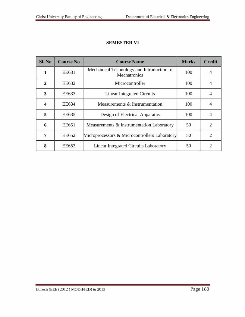
Christ University Faculty of Engineering Department of Electrical & Electronics Engineering
B.Tech (EEE) 2012 ( MODIFIED) & 2013 Page 160
SEMESTER VI
Sl. No Course No Course Name Marks Credit
1 EE631 Mechanical Technology and Introduction to
Mechatronics 100 4
2 EE632 Microcontroller 100 4
3 EE633 Linear Integrated Circuits 100 4
4 EE634 Measurements & Instrumentation 100 4
5 EE635 Design of Electrical Apparatus 100 4
6 EE651 Measurements & Instrumentation Laboratory 50 2
7 EE652 Microprocessors & Microcontrollers Laboratory 50 2
8 EE653 Linear Integrated Circuits Laboratory 50 2
Christ University Faculty of Engineering Department of Electrical & Electronics Engineering
B.Tech (EEE) 2012 ( MODIFIED) & 2013 Page 161
EE631 Mechanical Technology and Introduction to Mechatronics
UNIT 1
Air Standard Cycles: Assumptions made in air standard cycle; Otto cycle; diesel cycle,
dual combustion cycle, Derivation for efficiency.
IC Engines : classification of I.C. Engines, SI and CI engines, four stroke and two stroke
operation, stages of combustion with P-V and P-θ representation, Wankel Engines.
Dynamometers-Mechanical, hydraulic and Electrical. Working principle. Performance
Testing, parameters like various efficiencies, Power, fuel consumption-problems
UNIT 2
TURBOMACHINE Definition and parts of a Turbomachine; Comparison with positive
displacement machine; Classification: Second Laws Efficiencies. Energy transfer in turbo
machine: Euler Turbine equation; Alternate form of Euler turbine equation –
components of energy transfer; Degree of reaction.
centrifugal pumps General analysis, single and multi satage pumps, head, Theoretical
head – capacity relationship; concepts of Priming, slip, cavitation.
Reciprocating Pumps, nomenclatures, single and double acting, work done and
Efficiency
UNIT 3
STEAM TURBINES: Classification, Single stage impulse turbine; Condition for
maximum blade efficiency, stage efficiency. Compounding – Need for compounding,
method of compounding. Impulse Staging – Condition for maximum utilization factor for
multi stage turbine with equiangular blades; effect of blades and nozzle losses.
Reaction turbine; Parson‟s reaction turbine, condition for maximum blade efficiency,
reaction staging.
Gas Turbines: Brayton cycle; Components of a gas turbine plant; open and closed types
of gas turbine plants; Optimum pressure ratio; Improvements of the basic gas turbine
cycle; multi stage compression with inter-cooling; multi stage expansion with reheating
between stages; exhaust gas heat exchanger, Applications of gas turbines. Problems on
single stage only.
UNIT 4
HYDRAULIC TURBINES: Classification; Pelton Turbine-velocity triangles, Design
parameters, turbine efficiency, volumetric efficiency; Francis turbine – velocity
triangles, runner shapes for different blade speeds, Design of Francis turbine; Function of
a Draft tube, types of draft tubes; Kaplan and Propeller turbines – Velocity triangles and
design parameters.
UNIT 5
Christ University Faculty of Engineering Department of Electrical & Electronics Engineering
B.Tech (EEE) 2012 ( MODIFIED) & 2013 Page 162
Introduction to Mechatronic Systems: Measurement and control systems Their elements
and functions, Microprocessor based controllers.
Review of Transducers and Sensors: Definition and classification of transducers.
Definition and classification of sensors. Principle of working and applications of light
sensors, proximity sensors and Hall effect sensors.
TEXT BOOKS
1. An Introduction to energy conversion, Volume III – Turbo machinery, V. Kadambi
and Manohar Prasad, New Age International Publishers (P) Ltd.
2. “Turbines, Compressors & Fans”, S. M. Yahya, Tata-McGraw Hill Co., 2
ndEdition ,2002
3. Introduction Mechatronics & Measurement systems, David.G. Aliciatore & Michael. B.
Bihistaned, Tata McGraw Hill, 2000.
4. Mechatronics - Principles, Concepts and applications – Nitaigour and Premchand Mahilik
- Tata McGraw Hill- 2003.
Christ University Faculty of Engineering Department of Electrical & Electronics Engineering
B.Tech (EEE) 2012 ( MODIFIED) & 2013 Page 163
EE632 MICROCONTROLLERS
AIM
To expose the students to the fundamentals of microcontroller based system design.
OBJECTIVES
To impart knowledge on 8051 Microcontroller based system and Microchip PIC 8
bit microcontroller based system.
UNIT I 8051 ARCHITECTURE
Architecture – memory organization – addressing modes – instruction set – Timers -
Interrupts - I/O ports, Interfacing I/O Devices – Serial Communication.
UNIT II 8051 PROGRAMMING
Assembly language programming – Arithmetic Instructions – Logical Instructions –
Single bit Instructions – Timer Counter Programming – Serial Communication
Programming Interrupt Programming – RTOS for 8051 – RTOSLite – FullRTOS –Task
creation and run – LCD digital clock/thermometer using FullRTOS, Introduction to
Embedded C
UNIT III PIC MICROCONTROLLER
Architecture – memory organization – addressing modes – instruction set – PIC
progrmming in Assembly & C –I/O port, Data Conversion, RAM & ROM Allocation,
Timer programming, MP-LAB.
UNIT IV PERIPHERAL OF PIC MICROCONTROLLER
Timers – Interrupts, I/O ports- I2C bus-A/D converter-UART- CCP modules -ADC,
DAC and Sensor Interfacing –Flash and EEPROM memories.
UNIT V SYSTEM DESIGN – CASE STUDY
Interfacing LCD Display – Keypad Interfacing - Generation of Gate signals for
converters and Inverters - Motor Control – Controlling AC appliances –Measurement of
frequency Stand alone Data Acquisition System.
Christ University Faculty of Engineering Department of Electrical & Electronics Engineering
B.Tech (EEE) 2012 ( MODIFIED) & 2013 Page 164
REFERENCES
1. Muhammad Ali Mazidi, Rolin D. Mckinlay, Danny Causey ‘ PIC Microcontroller
and Embedded Systems using Assembly and C for PIC18’, Pearson Education
2008
2. Muhammad Ali Mazidi, Rolin D. Mckinlay, Danny Causey ‘ 8051
Microcontroller and
Embedded Systems using Assembly and C for ’
3. John Iovine, ‘PIC Microcontroller Project Book ’, McGraw Hill 2000\
4. Myke Predko, “Programming and customizing the 8051 microcontroller”, Tata
McGraw Hill 2001.
Christ University Faculty of Engineering Department of Electrical & Electronics Engineering
B.Tech (EEE) 2012 ( MODIFIED) & 2013 Page 165
EE633 LINEAR INTEGRATED CIRCUITS
AIM
To teach the basic concepts in the design of electronic circuits using linear integrated
circuits and their applications in the processing of analog signals.
OBJECTIVES
To introduce the basic building blocks of linear integrated circuits.
To teach the linear and non-linear applications of operational amplifiers.
To introduce the theory and applications of analog multipliers and PLL.
To teach the theory of ADC and DAC
To introduce a few special function integrated circuits.
UNIT I CIRCUIT CONFIGURATION FOR LINEAR ICs 9 + 3
Current sources, Analysis of difference amplifiers with active loads, supply and
temperature independent biasing, Band gap references, Monolithic IC operational
amplifiers, specifications, frequency compensation, slew rate and methods of improving
slew rate.
UNIT II APPLICATIONS OF OPERATIONAL AMPLIFIERS 9 + 3
Linear and Nonlinear Circuits using operational amplifiers and their analysis, Inverting
and Non inverting Amplifiers, Differentiator, Integrator, Voltage to current converter,
Instrumentation amplifier, Sine wave Oscillator, Low-pass and band-pass filters,
Comparator, Multivibrators and Schmitt trigger, Triangular wave generator, Precision
rectifier, Log and Antilog amplifiers, Non-linear function generator.
UNIT III ANALOG MULTIPLIER AND PLL 9 + 3
Analysis of four quadrant (Gilbert cell) and variable transconductance multipliers,
Voltage controlled Oscillator, Closed loop analysis of PLL, AM, PM and FSK
modulators and demodulators, Frequency synthesizers, Compander ICs.
UNIT IV: ANALOG TO DIGITAL AND DIGITAL TO ANALOG CONVERTERS
9 + 3
Christ University Faculty of Engineering Department of Electrical & Electronics Engineering
B.Tech (EEE) 2012 ( MODIFIED) & 2013 Page 166
Analog switches, High speed sample and hold circuits and sample and hold ICs, Types of
D/A converter, Current driven DAC, Switches for DAC, A/D converter-Flash, Single
slope, Dual slope, Successive approximation, Delta Sigma Modulation.
UNIT V SPECIAL FUNCTION ICS 9 + 3
Astable and Monostable Multivibrators using 555 Timer, Voltage regulators-linear and
switched mode types, Switched capacitor filter, Frequency to Voltage converters, Voltage
to Time converters ,Tuned amplifiers.
L = 45 T = 15 Total = 60
TEXT BOOK
1. Sergio Franco, ‘Design with operational amplifiers and analog integrated
circuits’, McGraw-Hill, 1997.
2. D.Roy Choudhry, Shail Jain, “Linear Integrated Circuits”, New Age International
Pvt. Ltd., 2000.
REFERENCES
1. Gray and Meyer, ‘Analysis and Design of Analog Integrated Circuits’, Wiley
International, 1995.
2. J.Michael Jacob, ‘Applications and Design with Analog Integrated Circuits’,
Prentice Hall of India, 1996.
3. Ramakant A.Gayakwad, ‘OP-AMP and Linear IC’s’, Prentice Hall / Pearson
Education, 1994.
4. K.R.Botkar, ‘Integrated Circuits’. Khanna Publishers, 1996.
5. Taub and Schilling, Digital Integrated Electronics, McGraw-Hill, 1997.
6. Millman.J. and Halkias.C.C. ‘Integrated Electronics’, McGraw-Hill, 1972.
Christ University Faculty of Engineering Department of Electrical & Electronics Engineering
B.Tech (EEE) 2012 ( MODIFIED) & 2013 Page 167
EE634 MEASUREMENTS AND INSTRUMENTATION
AIM
To provide adequate knowledge in electrical instruments and measurements
techniques.
OBJECTIVES
To make the student have a clear knowledge of the basic laws governing the
operation of the instruments, relevant circuits and their working.
i. Introduction to general instrument system, error, calibration etc.
ii. Emphasis is laid on analog and digital techniques used to measure voltage,
current, energy and power etc.
iii. To have an adequate knowledge of comparison methods of measurement.
iv. Elaborate discussion about storage & display devices.
v. Exposure to various transducers and data acquisition system.
UNIT I: INTRODUCTION 9 + 3
Functional elements of an instrument – Static and dynamic characteristics –
Errors in measurement – Statistical evaluation of measurement data – Standards and
calibration.
UNIT II: ELECTRICAL AND ELECTRONICS INSTRUMENTS 9 + 3
Principle and types of analog and digital voltmeters, ammeters, multimeters –
Single and three phase wattmeters and energy meters – Magnetic measurements –
Determination of B-H curve and measurements of iron loss – Instrument transformers –
Instruments for measurement of frequency and phase.
UNIT III: COMPARISON METHODS OF MEASUREMENTS 9 + 3
D.C & A.C potentiometers, D.C & A.C bridges, transformer ratio bridges, self-balancing
bridges. Interference & screening – Multiple earth and earth loops - Electrostatic and
electromagnetic interference – Grounding techniques.
UNIT IV: STORAGE AND DISPLAY DEVICES 9 + 3
Magnetic disk and tape – Recorders, digital plotters and printers, CRT display,
digital CRO, LED, LCD & dot matrix display.
Christ University Faculty of Engineering Department of Electrical & Electronics Engineering
B.Tech (EEE) 2012 ( MODIFIED) & 2013 Page 168
UNIT V: TRANSDUCERS AND DATA ACQUISITION SYSTEMS 9 + 3
Classification of transducers – Selection of transducers – Resistive, capacitive &
inductive transducers – Piezoelectric, optical and digital transducers – Elements of data
acquisition system – A/D, D/A converters.
TEXT BOOKS
1. E.O. Doebelin, ‘Measurement Systems – Application and Design’, Tata McGraw
Hill publishing company, 2003.
2. A.K. Sawhney, ‘A Course in Electrical & Electronic Measurements &
Instrumentation’, Dhanpat Rai and Co, 2004.
REFERENCE BOOKS
1. A.J. Bouwens, ‘Digital Instrumentation’, Tata McGraw Hill, 1997.
2. D.V.S. Moorthy, ‘Transducers and Instrumentation’, Prentice Hall of India Pvt
Ltd, 2003.
3. H.S. Kalsi, ‘Electronic Instrumentation’, Tata McGraw Hill, 1995.
4. Martin Reissland, ‘Electrical Measurements’, New Age International (P) Ltd.,
Delhi, 2001.
5. J. B. Gupta, ‘A Course in Electronic and Electrical Measurements’, S. K. Kataria
& Sons, Delhi, 2003.
Christ University Faculty of Engineering Department of Electrical & Electronics Engineering
B.Tech (EEE) 2012 ( MODIFIED) & 2013 Page 169
EE635 DESIGN OF ELECTRICAL APPARATUS
AIM
To expose the students to the concept of design of various types of electrical
machines.
OBJECTIVES
To provide sound knowledge about constructional details and design of various
electrical machines.
To study mmf calculation and thermal rating of various types of electrical
machines.
To design armature and field systems for D.C. machines.
To design core, yoke, windings and cooling systems of transformers.
To design stator and rotor of induction machines.
To design stator and rotor of synchronous machines and study their thermal
behaviour.
UNIT I: MAGNETIC CIRCUITS AND COOLING OF ELECTICAL MACHINES 9 + 3
Concept of magnetic circuit – MMF calculation for various types of electrical
machines – real and apparent flux density of rotating machines – leakage reactance
calculation for transformers, induction and synchronous machine - thermal rating:
continuous, short time and intermittent short time rating of electrical machines-direct and
indirect cooling methods – cooling of turbo alternators.
UNIT II: D.C. MACHINES 9 + 3
Constructional details – output equation – main dimensions - choice of specific
loadings – choice of number of poles – armature design – design of field poles and field
coil – design of commutator and brushes – losses and efficiency calculations.
UNIT III: TRANSFORMERS 9 + 3
Constructional details of core and shell type transformers – output rating of single
phase and three phase transformers – optimum design of transformers – design of core,
yoke zand windings for core and shell type transformers – equivalent circuit parameter
from designed data – losses and efficiency calculations – design of tank and cooling tubes
of transformers.
Christ University Faculty of Engineering Department of Electrical & Electronics Engineering
B.Tech (EEE) 2012 ( MODIFIED) & 2013 Page 170
UNIT IV: THREE PHASE INDUCTION MOTORS 9 + 3
Constructional details of squirrel cage and slip ring motors – output equation –
main dimensions – choice of specific loadings – design of stator – design of squirrel cage
and slip ring rotor – equivalent circuit parameters from designed data – losses and
efficiency calculations.
UNIT V: SYNCHRONOUS MACHINES 9 + 3
Constructional details of cylindrical pole and salient pole alternators – output
equation – choice of specific loadings – main dimensions – short circuit ratio – design of
stator and rotor of cylindrical pole and salient pole machines - design of field coil -
performance calculation from designed data - introduction to computer aided design.
L = 45 T = 15 Total = 60
TEXT BOOKS
1. A.K. Sawhney, ‘A Course in Electrical Machine Design’, Dhanpat Rai and Sons,
New Delhi, 1984.
2. S.K. Sen, ‘Principles of Electrical Machine Design with Computer Programmes’,
Oxford and IBH Publishing Co.Pvt Ltd., New Delhi, 1987.
REFERENCE BOOKS
1. R.K. Agarwal, ‘Principles of Electrical Machine Design’, S.K.Kataria and Sons,
Delhi, 2002.
2. V.N. Mittle and A. Mittle, ‘Design of Electrical Machines’, Standard
Publications and Distributors, Delhi, 2002.
Christ University Faculty of Engineering Department of Electrical & Electronics Engineering
B.Tech (EEE) 2012 ( MODIFIED) & 2013 Page 171
EE651 MEASUREMENTS AND INSTRUMENTATION LABORATORY
AIM
The aim of this lab is to fortify the students with an adequate work experience in
the measurement of different quantities and also the expertise in handling the instruments
involved.
OBJECTIVE
To train the students in the measurement of displacement, resistance, inductance,
torque and angle etc., and to give exposure to AC, DC bridges and transient
measurement.
1. Study of displacement and pressure transducers
2. AC bridges.
3. DC bridges.
4. Instrumentation amplifiers.
5. A/D and D/A converters.
6. Study of transients.
7. Calibration of single-phase energy meter.
8. Calibration of current transformer.
9. Measurement of three phase power and power factor.
10. Measurement of iron loss.
Detailed Syllabus
1(a). Study of Displacement Transducer - LVDT
Aim
To study the operation of LVDT
Objectives
1. To study the basic principle of LVDT.
2. Study of signal conditioning circuit.
3. Study of LVDT as transducer.
Christ University Faculty of Engineering Department of Electrical & Electronics Engineering
B.Tech (EEE) 2012 ( MODIFIED) & 2013 Page 172
Exercise
1. Draw the characteristic curve for a given LVDT.
2. Find the residual voltage.
3. Fluid the non-electrical quantity displacement interms of voltage.
Equipment
1. LVDT kit – 1 No
2. Multimeter – 1 No
1(b). Study of Pressure Transducer
Aim
To study the operation of bourdon tube
Objectives
1. To study the basic principle of Bourdon tube.
2. Study of Bourdon tube as transducer.
Exercise
1. Draw the characteristic curve for a given Bourdon tube i.e. pressure vs. o/p (V
or I).
2. Measure the non-electrical quantity pressure interms of voltage or current.
Equipment
1. Bourdon pressure transducer kit – 1 No
2. Foot pump – 1 No
3. Voltmeter – 1 No
4. Multimeter – 1 No
2. AC BRIDGES
a) Maxwell’s Inductance – Capacitance Bridge
Aim
To find the unknown inductance and Q factor of a given coil.
Objective
1. To find the unknown inductance of the given coil using bridge circuit.
2. To study that Maxwell inductance, Capacitance Bridge is suitable for the
measurement of law Q coils.
Christ University Faculty of Engineering Department of Electrical & Electronics Engineering
B.Tech (EEE) 2012 ( MODIFIED) & 2013 Page 173
Exercise
1. Design a bridge circuit for the given parameters.
2. Fluid Q factor of the coil.
3. Fluid unknown Inductance.
Equipment
1. Maxwell’s inductance Capacitance Bridge kit – 1 No
2. Multimeter – 1 No
3. Unknown Inductance – 1 No
b) Schering Bridge
Aim
To measure the unknown capacitance using Schering bridge.
Objective
1. To measure the unknown capacitance.
2. To study about dissipation factor.
Exercise
1. Design a bridge circuit for the given parameters. 2. Find the dissipation factor. 3. Fluid the unknown capacitance.
Equipment
1. Schering Bridge kit – 1 No
2. Multimeter – 1 No
3. Unknown capacitance – 1 No
3. DC Bridges
a) Wheat Stone Bridge
Aim
To measure the given medium resistance using Wheatstone Bridge.
Objective
1. To study the working of bridge under balanced and unbalanced condition.
2. To study the sensitivity of bridge.

Christ University Faculty of Engineering Department of Electrical & Electronics Engineering
B.Tech (EEE) 2012 ( MODIFIED) & 2013 Page 174
Exercise
1. Design a bridge for the given parameters.
2. Find the unknown resistance.
3. Find the sensitivity of Bridge.
Equipment
1. Wheat stone Bridge kit – 1 No
2. Unknown resistance – 1 No
3. Multimeter – 1 No
b) Kelvin’s Double bridge
Aim
To measure the given low resistance using Kelvin’s double bridge method.
Objective
1. To study the working of bridge under balanced and unbalance condition.
2. To study the sensitivity of bridge.
Exercise
1. Design a bridge for the given parameters.
2. Find the unknown low resistance.
3. Find the sensitivity of bridge.
Equipment
1. Kelvin Double bridge kit – 1 No
2. Unknown resistance – 1 No
3. Multimeter – 1 No
4. Instrumentation Amplifier
Aim
To study the working of instrumentation amplifier.
Objective
1. To study the characteristic of operational amplifier.
2. To study the use of operational amplifier as instrumentation amplifier.
Christ University Faculty of Engineering Department of Electrical & Electronics Engineering
B.Tech (EEE) 2012 ( MODIFIED) & 2013 Page 175
Exercise
1. Measure the output voltage for varying input voltage.
2. Calculate the output voltage theoretically.
3. Calculate the error.
Equipment
1. Operational Amplifier – 1 No
2. Resistors – 1 No
3. RPS – 1 No
4. Voltmeter – 1 No
5. Multimeter – 1 No
5(a) A/D Converter
Aim
To design and test a 4 bit A/D converter
1. Successive approximation type
2. Ramp type
Objective
1. To study the conversation of analog I/P voltage to digital o/p voltage.
2. To study the operation and characteristic of operational amplifier
Exercise
1. Given 4 bit analog input is converted to digital output
2. Verify the practical output with theoretical output
Equipment
1. IC 741 – 1 No
2. DC trainer kit – 1 No
3. RPS – 1 No
4. Resistor – 1 No
5. CRO – 1 No
(b) D/A Converter
Aim
To design and test a 4 bit D/A converter
1. Weighted resistor technique
2. R-2R ladder network
Objective
Christ University Faculty of Engineering Department of Electrical & Electronics Engineering
B.Tech (EEE) 2012 ( MODIFIED) & 2013 Page 176
1. To study the conversion of binary voltage to analog o/p voltage
2. To study the operation and characteristic of operational amplifier
Exercise
1. Given 4 bit binary input is converted to analog output
2. Verify the practical o/p with theoretical o/p
Experiment
1. IC 741 – 1 No
2. DC Trainer kit – 1 No
3. RPS – 1 No
4. Resistor – 1 No
5. CRO – 1 No
6. Study of Transients
Aim
To study the transient response of the given system
Objective
1. To study the transient behaviour of the given system
2. To study the effects of transients
Exercise
1. Draw the response curve for the given system
2. Find the time when the error is minimum
Equipment
1. Resistance – 1 No
2. Capacitance – 1 No
3. RPS – 1 No
4. Voltmeter – 1 No
5. Multimeter – 1 No
7. Calibration of Single-Phase Energy Meter
Aim
To calibrate the given single phase energy meter at unity and other power factors
Objectives
Christ University Faculty of Engineering Department of Electrical & Electronics Engineering
B.Tech (EEE) 2012 ( MODIFIED) & 2013 Page 177
1. To study the working of energy meter
2. Too accurately calibrate the meter at unity and other power factor
3. To study the % of errors for the given energy meters
Exercise
1. Measure the experimental energy consumed
2. Calculate the theoretical energy
3. Calculate the percentage of error
4. Draw the calibration curve
Equipment
1. Energy meter – 1 No
2. Wattmeter – 1 No
3. Stop watch – 1 No
4. M.I Ammeter – 1 No
5. M.I Voltmeter – 1 No
8. Calibration of Current Transformer
Aim
To study the working of current transformer
Objective
1. To study the current transformation concept
2. To study the efficiency of a given current transformer
3. To study the loss components in the circuit
Exercise
1. Draw the curve primary current Vs secondary current
2. Observe the o/p for lamp load
3. Calculate the efficiency
Equipment
1. Current Transformer – 1 No
2. Lamp Load – 1 No
3. Voltmeter – 1 No
4. Ammeter – 1 No
9. Measurement of 3 Phase Power And Power Factor
Aim
Christ University Faculty of Engineering Department of Electrical & Electronics Engineering
B.Tech (EEE) 2012 ( MODIFIED) & 2013 Page 178
To conduct a suitable experiment on a 3-phase load connected in star or delta to
measure the three phase power and power factor using 2 wattmeter method.
Objectives
1. To study the working of wattmeter
2. To accurately measure the 3 phase power
3. To accurately measure the powerfactor
4. To study the concept of star connected load and delta connected load
Exercise
1. Measure the real power, reactive power and power factor of 3 phase resistive
inductive load.
2. Measure the real power, reactive power and power factor of 3 phase resistive
capacitive load.
Equipment
1. 3 phase Auto transformer – 1 No
2. M.I Ammeter – 1 No
3. M.I Voltmeter – 1 No
4. Wattmeter – 1 No
10. Measurement of Iron Loss (Maxwell Bridge)
Aim
To determine the iron losses in magnetic material using bridge method
Objective
1. To study about hysteresis loss
2. To study about eddy current loss
Exercise
1. Measure the current
2. Calculate iron loss
3. Calculate AC permeability
4. Draw phasor diagram
Equipment
1. Maxwell bridge set up – 1 No

Christ University Faculty of Engineering Department of Electrical & Electronics Engineering
B.Tech (EEE) 2012 ( MODIFIED) & 2013 Page 179
2. Ring specimen – 1 No
3. Ammeter – 1 No
4. Galvanometer – 1 No
Christ University Faculty of Engineering Department of Electrical & Electronics Engineering
B.Tech (EEE) 2012 ( MODIFIED) & 2013 Page 180
EE652 MICROPROCESSORS AND MICROCONTROLLERS
LABORATORY
1. Programs for 8/16 bit Arithmetic operations (Using 8085).
2. Programs for Sorting and Searching (Using 8085, 8086).
3. Programs for String manipulation operations (Using 8086).
4. Programs for Digital clock and Stop watch (Using 8086).
5. Interfacing ADC and DAC.
6. Parallel Communication between two MP Kits using Mode 1 and Mode 2 of
8255.
7. Interfacing and Programming 8279, 8259, and 8253.
8. Serial Communication between two MP Kits using 8251.
9. Interfacing and Programming of Stepper Motor and DC Motor Speed control.
10. Programming using Arithmetic, Logical and Bit Manipulation instructions of
8051microcontroller.
11. Programming and verifying Timer, Interrupts and UART operations in 8031
microcontroller.
12. Communication between 8051 Microcontroller kit and PC.
P = 45 Total = 45
Christ University Faculty of Engineering Department of Electrical & Electronics Engineering
B.Tech (EEE) 2012 ( MODIFIED) & 2013 Page 181
EE653 LINEAR INTEGRATED CIRCUITS LABORATORY
Design and testing of:
1. Inverting, Non inverting and differential amplifiers.
2. Integrator and Differentiator.
3. Instrumentation amplifier.
4. Active lowpass and bandpass filter.
5. Astable, Monostable multivibrators and Schmitt Trigger using op-amp.
6. Phase shift and Wien bridge oscillator using op-amp.
7. Astable and monostable using NE555 Timer.
8. PLL characteristics and Frequency Multiplier using PLL.
9. DC power supply using LM317 and LM723.
10. Study of SMPS control IC SG3524 / SG3525.
P = 45 Total = 45
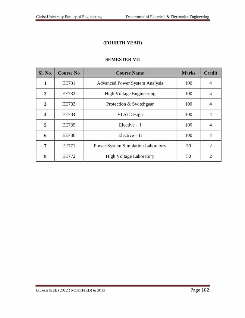
Christ University Faculty of Engineering Department of Electrical & Electronics Engineering
B.Tech (EEE) 2012 ( MODIFIED) & 2013 Page 182
(FOURTH YEAR)
SEMESTER VII
Sl. No. Course No Course Name Marks Credit
1 EE731 Advanced Power System Analysis 100 4
2 EE732 High Voltage Engineering 100 4
3 EE733 Protection & Switchgear 100 4
4 EE734 VLSI Design 100 4
5 EE735 Elective – I 100 4
6 EE736 Elective – II 100 4
7 EE771 Power System Simulation Laboratory 50 2
8 EE772 High Voltage Laboratory 50 2
Christ University Faculty of Engineering Department of Electrical & Electronics Engineering
B.Tech (EEE) 2012 ( MODIFIED) & 2013 Page 183
EE731 ADVANCED POWER SYSTEM ANALYSIS
Unit 1
Load Flow - Network modeling – Conditioning of Y Matrix – Load flow-Newton
Raphson method- Decoupled – Fast decoupled Load flow -three-phase load flow
Unit 2
DC power flow –Single phase and three phase -AC-DC load flow - DC system model –
Sequential Solution Techniques – Extension to Multiple and or Multi-terminal DC
systems – DC
convergence tolerance – Test System and results.
Unit 3
Fault Studies -Analysis of balanced and unbalanced three phase faults – fault calculations
– Short
circuit faults – open circuit faults
Unit 4
System optimization - strategy for two generator system – generalized strategies – effect
of transmission losses - Sensitivity of the objective function- Formulation of optimal
power flowsolution by Gradient method-Newton’s method.
Unit 5
State Estimation – method of least squares – statistics – errors – estimates – test for bad
data – structure and formation of Hessian matrix – power system state estimation.
Reference
1. Grainger, J.J. and Stevenson, W.D. „Power System Analysis, Tata McGraw hill, New
Delhi, 2003.
2. Arrillaga, J and Arnold, C.P., „Computer analysis of power systems, John Wiley and
Sons, New York, 1997.
3. Pai, M.A., „Computer Techniques in Power System Analysis, Tata McGraw hill, New
Delhi, 2006.
Christ University Faculty of Engineering Department of Electrical & Electronics Engineering
B.Tech (EEE) 2012 ( MODIFIED) & 2013 Page 184
EE732 HIGH VOLTAGE ENGINEERING
AIM
To expose the students to various types of over voltage transients in power system and its
effect on power system.
- Generation of over voltages in laboratory
- Testing of power apparatus and system.
OBJECTIVES
i. To understand the various types of over voltages in power system and protection
methods, generation of over voltages in laboratories.
ii. Measurement of over voltages.
iii. Nature of Breakdown mechanism in solid, liquid and gaseous dielectrics –
discussion on commercial insulants.
iv. Testing of power apparatus and insulation coordination
UNIT I: OVER VOLTAGES IN ELECTRICAL POWER SYSTEMS 6 + 3
Causes of over voltages and its effect on power system – Lightning, switching surges and
temporary over voltages - protection against over voltages.
UNIT II: Electrical Breakdown in Gases, Solids and Liquids 10 + 3
Gaseous breakdown in uniform and non-uniform fields – corona discharges – Vacuum
breakdown - conduction and breakdown in pure and commercial liquids – breakdown
mechanisms in solid and composite dielectrics.
UNIT III: Generation of High Voltages and High Currents 10 + 3
Generation of High DC, AC, impulse voltages and currents. Tripping and control of
impulse generators.
UNIT IV: Measurement of High Voltages and High Currents 10 + 3
Measurement of High voltages and High currents – digital techniques in high voltage
measurement.
UNIT V: High Voltage Testing & Insulation Coordination 9 + 3
High voltage testing of electrical power apparatus – power frequency, impulse voltage
and DC testing – International and Indian standards – Insulation Coordination.
Christ University Faculty of Engineering Department of Electrical & Electronics Engineering
B.Tech (EEE) 2012 ( MODIFIED) & 2013 Page 185
TEXT BOOK
1. M.S. Naidu and V. Kamaraju, ‘High Voltage Engineering’, Tata McGraw Hill, 3rd
Edition, 2004.
REFERENCE BOOKS
1. E. Kuffel and W.S. Zaengl, ‘High Voltage Engineering Fundamentals’, Pergamon
press, Oxford, London, 1986.
2. E. Kuffel and M. Abdullah, ‘High Voltage Engineering’, Pergamon press, Oxford,
1970.
Christ University Faculty of Engineering Department of Electrical & Electronics Engineering
B.Tech (EEE) 2012 ( MODIFIED) & 2013 Page 186
EE733 PROTECTION AND SWITCHGEAR
AIM
To expose the students to the various faults in power system and learn the various
methods of protection scheme
To understand the current interruption in Power System and study the various
switchgears.
OBJECTIVES
i. Discussion on various earthing practices usage of symmetrical components to
estimate fault current and fault MVA.
ii. Study of Relays & Study of protection scheme, solid state relays.
iii. To understand instrument transformer and accuracy.
iv. To understand the method of circuit breaking various arc theories Arcing
phenomena – capacitive and inductive breaking.
v. Types of circuit breakers.
UNIT I: INTRODUCTION 9 + 3
Principles and need for protective schemes – nature and causes of faults – types of faults
– fault current calculation using symmetrical components – Power system earthing -
Zones of protection and essential qualities of protection – Protection scheme.
UNIT II: OPERATING PRINCIPLES AND RELAY CONSTRUCTIONS 9 + 3
Electromagnetic relays – Over current, directional, distance and differential, under
frequency relays – static relays.
UNIT III: APPARATUS PROTECTION 9 + 3
Apparatus protection transformer, generator, motor, protection of bus bars, transmission lines – CTs and PTs and their applications in protection schemes.
UNIT IV: THEORY OF CIRCUIT INTERRUPTION 9 + 3
Physics of arc phenomena and arc interruption. Restriking voltage & Recovery voltage,
rate of rise of recovery voltage, resistance switching, current chopping, interruption of
capacitive current – DC circuit breaking.
Christ University Faculty of Engineering Department of Electrical & Electronics Engineering
B.Tech (EEE) 2012 ( MODIFIED) & 2013 Page 187
UNIT V: CIRCUIT BREAKERS 9 + 3
Types of Circuit Breakers – Air blast, Air break, oil SF6 and Vacuum circuit breakers –
comparative merits of different circuit breakers – Testing of circuit breakers.
L = 45 T = 15 Total = 60
TEXT BOOKS
1. B. Ravindranath, and N. Chander, ‘Power System Protection & Switchgear’,
Wiley Eastern Ltd., 1977.
REFERENCE BOOKS
1. Sunil S. Rao, ‘Switchgear and Protection’, Khanna publishers, New Delhi, 1986 .
2. C.L. Wadhwa, ‘Electrical Power Systems’, Newage International (P) Ltd., 2000.
3. M.L. Soni, P.V. Gupta, V.S. Bhatnagar, A. Chakrabarti, ‘A Text Book on Power
System Engineering’, Dhanpat Rai & Co., 1998.
4. Badri Ram, Vishwakarma, ‘Power System Protection and Switchgear’, Tata
McGraw hill, 2001.
5. Y.G. Paithankar and S.R. Bhide, ‘Fundamentals of Power System Protection’,
Prentice Hall of India Pvt. Ltd., New Delhi – 110001, 2003.
Christ University Faculty of Engineering Department of Electrical & Electronics Engineering
B.Tech (EEE) 2012 ( MODIFIED) & 2013 Page 188
EE734 VLSI DESIGN
AIM
To introduce the technology & concepts of VLSI.
OBJECTIVES
To introduce MOS theory / Manufacturing Technology.
To study inverter / counter logic / stick / machine diagram / sequential circuits.
To study address / memory / arithmetic circuits.
To introduce FPGA architecture / principles / system design
To get familiarised with VHDL programming behavioural/Structural/concurrent/
process.
UNIT I: BASIC MOS TRANSISTOR 9 + 3
Enhancement mode & Depletion mode – Fabrication (NMOS, PMOS, CMOS, BiCMOS)
Technology – NMOS transistor current equation – second order effects – MOS Transistor
Model.
UNIT II: NMOS & CMOS INVERTER AND GATES 9 + 3
NMOS & CMOS inverter – Determination of pull up / pull down ratios – stick diagram –
lamda based rules – super buffers – BiCMOS & steering logic.
UNIT III: SUB SYSTEM DESIGN & LAYOUT 9 + 3
Structured design of combinational circuits – Dynamic CMOS & clocking – Tally
circuits –(NAND-NAND, NOR-NOR and AOI logic) – EXOR structure – Multiplexer
structures – Barrel shifter.
UNIT IV: DESIGN OF COMBINATIONAL ELEMENTS & REGULAR ARRAY
LOGIC 9 + 3
NMOS PLA – Programmable Logic Devices - Finite State Machine PLA – Introduction
to FPGA.
UNIT V: VHDL PROGRAMMING 9 + 3
RTL Design – combinational logic – Types – Operators – Packages – Sequential circuit –
Sub programs – Test benches. (Examples: address, counters, flip flops, FSM,
Multiplexers / Demultiplexers).
Christ University Faculty of Engineering Department of Electrical & Electronics Engineering
B.Tech (EEE) 2012 ( MODIFIED) & 2013 Page 189
TEXT BOOKS
1. D.A.Pucknell, K.Eshraghian, ‘Basic VLSI Design’, 3rd Edition, Prentice Hall of
India, New Delhi, 2003.
2. Eugene D.Fabricius, ‘Introduction to VLSI Design’, Tata McGraw Hill, 1990.
REFERENCE BOOKS
1. N.H.Weste, ‘Principles of CMOS VLSI Design’, Pearson Education, India, 2002.
2. Charles H.Roth, ‘Fundamentals of Logic Design’, Jaico Publishing House, 1992.
3. Zainalatsedin Navabi, ‘VHDL Analysis and Modelling of Digital Systems’, 2nd
Edition, Tata McGraw Hill, 1998.
4. Douglas Perry, ‘VHDL Programming By Example’, Tata McGraw Hill, 3rd
Edition.

Christ University Faculty of Engineering Department of Electrical & Electronics Engineering
B.Tech (EEE) 2012 ( MODIFIED) & 2013 Page 190
EE751 POWER SYSTEM SIMULATION LABORATORY
AIM
To acquire software development skills and experience in the usage of standard packages
necessary for analysis and simulation of power system required for its planning,
operation and control.
OBJECTIVES
To develop simple C programs for the following basic requirements:
Formation of bus admittance and impedance matrices and network solution.
Power flow solution of small systems using simple method, Gauss-Seidel P.F.
method.
Unit Commitment and Economic Dispatch.
To acquire experience in the usage of standard packages for the following
analysis / simulation / control functions.
Steady-state analysis of large system using NRPF and FDPF methods.
Quasi steady-state (Fault) analysis for balanced and unbalanced faults.
Transient stability simulation of multi machine power system.
Simulation of Load-Frequency Dynamics and control of power system.
1. Computation of Parameters and Modelling of Transmission Lines
2. Formation of Bus Admittance and Impedance Matrices and Solution of Networks.
3. Load Flow Analysis - I : Solution of Load Flow And Related Problems Using
Gauss-Seidel Method
4. Load Flow Analysis - II: Solution of Load Flow and Related Problems Using
Newton-Raphson and Fast-Decoupled Methods
5. Fault Analysis
6. Transient and Small Signal Stability Analysis: Single-Machine Infinite Bus
System
7. Transient Stability Analysis of Multimachine Power Systems
8. Electromagnetic Transients in Power Systems
9. Load – Frequency Dynamics of Single- Area and Two-Area Power Systems
10. Economic Dispatch in Power Systems.
Christ University Faculty of Engineering Department of Electrical & Electronics Engineering
B.Tech (EEE) 2012 ( MODIFIED) & 2013 Page 191
Detailed Syllabus
1. COMPUTATION OF PARAMETERS AND MODELLING OF
TRANSMISSION LINES
Aim
To determine the positive sequence line parameters L and C per phase per kilometer
of a three phase single and double circuit transmission lines for different conductor
arrangements.
To understand modelling and performance of short, medium and long lines.
Exercises
Computation of series inductance and shunt capacitance per phase per km of a three
phase line with flat horizontal spacing for single stranded and bundle conductor
configuration.
Computation of series inductance and shunt capacitance per phase per km of a three
phase double circuit transmission line with vertical conductor arrangement with
bundle conductor.
Computation of voltage, current, power factor, regulation and efficiency at the
receiving end of a three phase Transmission line when the voltage and power at the
sending end are given. Use П model.
Computation of receiving end voltage of a long transmission for a given sending end
voltage and when the line is open circuited at receiving. Also compute the shunt
reactor compensation to limit the no load receiving end voltage to specified value.
Determination of the voltage profile along the long transmission line for the following
cases of loading at receiving end (i) no load (ii) rated load (iii) surge impedance
loading and (iv) receiving end short circuited.
2. FORMATION OF BUS ADMITTANCE AND IMPEDANCE MATRICES
AND SOLUTION OF NETWORKS
Aim
To understand the formation of network matrices, the bus admittance matrix Y and the
bus impedance matrix Z of a power network, to effect certain required changes on these
matrices and to obtain network solution using these matrices.
Christ University Faculty of Engineering Department of Electrical & Electronics Engineering
B.Tech (EEE) 2012 ( MODIFIED) & 2013 Page 192
Exercises
1.1 Write a program in C language for formation of bus admittance matrix Y of a power
network using the “Two-Rule Method”, given the data pertaining to the transmission
lines, transformers and shunt elements. Run the program for a sample 6 bus system
and compare the results with that obtained using a standard software.
1.2 Modify the program developed in 2.1 for the following:
(i) To obtain modified Y matrix for the outage of a transmission line, a transformer
and a shunt element.
(ii) To obtain network solution V given the current injection vector I
(iii) To obtain full Z matrix or certain specified columns of Z matrix.
Verify the correctness of the modified program using 6 bus sample system
* 2.3 Write a program in C language for forming bus impedance matrix Z using the
“Building Algorithm”.
* Optional (not mandatory)
EXPERIMENT 3
LOAD FLOW ANALYSIS - I : SOLUTION OF LOAD FLOW AND RELATED
PROBLEMS USING GAUSS-SEIDEL METHOD
Aim
(i) To understand, the basic aspects of steady state analysis of power systems that are
required for effective planning and operation of power systems.
(ii) To understand, in particular, the mathematical formulation of load flow model in
complex form and a simple method of solving load flow problems of small sized
system using Gauss-Seidel iterative algorithm
Exercises
1.1 Write a program in c language for iteratively solving load flow equations using
Gauss-Seidel method with provision for acceleration factor and for dealing with P-V
buses. Run the program for a sample 6 bus system (Base case) and compare the
results with that obtained using a standard software.
1.2 Solve the “Base case” in 3.1 for different values of acceleration factor, draw the
convergence characteristics “Iteration taken for convergence versus acceleration
factor” and determine the best acceleration factor for the system under study.
Christ University Faculty of Engineering Department of Electrical & Electronics Engineering
B.Tech (EEE) 2012 ( MODIFIED) & 2013 Page 193
1.3 Solve the “Base Case” in 3.1 for the following changed conditions and comment on
the results obtained, namely voltage magnitude of the load buses and transmission
losses:
(i) Dropping all shunt capacitors connected to network
(ii) Changing the voltage setting of generators Vgi over the range 1.00 to 1.05
(iii) Changing the tap setting of the transformers, ai, over the range 0.85 to 1.1
1.4 Resolve the base case in 3.1 after shifting generation from one generator bus to
another generator bus and comment on the MW loading of lines and transformers.
4. LOAD FLOW ANALYSIS – I: SOLUTION OF LOAD FLOW AND RELATED
PROBLEMS USING NEWTON-RAPHSON AND FAST DECOUPLED
METHODS
Aim
(i) To understand the following for medium and large scale power systems:
(a) Mathematical formulation of the load flow problem in real variable form
(b) Newton-Raphson method of load flow (NRLF) solution
(c) Fast Decoupled method of load flow (FDLF) solution
(ii) To become proficient in the usage of software for practical problem solving in the
areas of power system planning and operation.
(iii) To become proficient in the usage of the software in solving problems using
Newton-Raphson and Fast Decoupled load flow methods.
Exercises
1.1 Solve the load flow problem (Base case) of a sample 6 bus system using Gauss-
Seidel, Fast Decoupled and Newton-Raphson Load Flow programs for a mismatch
convergence tolerance of 0.01 MW, plot the convergence characteristics and
compare the convergence rate of the three methods.
1.2 Obtain an optimal (minimum transmission loss) load flow solution for the Base case
loading of 6 bus sample system by trial and error approach through repeated load
flow solutions using Fast Decoupled Load Flow package for different combinations
of generator voltage settings, transformer tap settings, and reactive power of shunt
elements.
1.3 Carry out contingency analysis on the optimal state obtained in 4.2 for outage of a
transmission line using FDLF or NRLF package.
Christ University Faculty of Engineering Department of Electrical & Electronics Engineering
B.Tech (EEE) 2012 ( MODIFIED) & 2013 Page 194
1.4 Obtain load flow solutions using FDLF or NRLF package on the optimal state
obtained in 4.2 but with reduced power factor (increased Q load) load and comment
on the system voltage profile and transmission loss.
1.5 Determine the maximum load ability of a 2 bus system using analytical solution as
well as numerical solution using FDLF package. Draw the P-V curve of the system.
1.6 For the base case operating state of the 6 bus system in 4.1 draw the P-V curve for
the weakest load bus. Also obtain the voltage Stability Margin (MW Index) at
different operating states of the system.
5. FAULT ANALYSIS
Aim
To become familiar with modelling and analysis of power systems under faulted
condition and to compute the fault level, post-fault voltages and currents for
different types of faults, both symmetric and unsymmetric.
Exercises
1.1 Calculate the fault current, post fault voltage and fault current through the branches
for a three phase to ground fault in a small power system and also study the effect of
neighbouring system. Check the results using available software.
1.2 Obtain the fault current, fault MVA, Post-fault bus voltages and fault current
distribution for single line to ground fault, line-to-line fault and double line to ground
fault for a small power system, using the available software. Also check the fault
current and fault MVA by hand calculation.
1.3 Carryout fault analysis for a sample power system for LLLG, LG, LL and LLG faults
and prepare the report.
6. TRANSIENT AND SMALL-SIGNAL STABILITY ANALYSIS: SINGLE
MACHINE-INFINITE BUS SYSTEM
Aim
To become familiar with various aspects of the transient and small signal stability
analysis of Single-Machine Infinite Bus (SMIB) system.
Exercises
For a typical power system comprising a generating, step-up transformer, double-circuit
transmission line connected to infinite bus:
Christ University Faculty of Engineering Department of Electrical & Electronics Engineering
B.Tech (EEE) 2012 ( MODIFIED) & 2013 Page 195
Transient Stability Analysis
6.1 Hand calculation of the initial conditions necessary for the classical model of the
synchronous machine.
1.1 Hand computation of critical clearing angle and time for the fault using equal area
criterion.
1.2 Simulation of typical disturbance sequence: fault application, fault clearance by
opening of one circuit using the software available and checking stability by plotting
the swing curve.
1.3 Determination of critical clearing angle and time for the above fault sequence
through trial and error method using the software and checking with the hand
computed value.
1.4 Repetition of the above for different fault locations and assessing the fault severity
with respect to the location of fault
1.5 Determination of the steady-state and transient stability margins.
Small-signal Stability Analysis:
1.6 Familiarity with linearised swing equation and characteristic equation and its roots,
damped frequency of oscillation in Hz, damping ratio and undamped natural
frequency. Force-free time response for an initial condition using the available
software. Effect of positive, negative and zero damping.
7. TRANSIENT STABILITY ANALYSIS OF MULTIMACHINE POWER
SYSTEMS
Aim
To become familiar with modelling aspects of synchronous machines and network,
state-of-the-art algorithm for simplified transient stability simulation, system
behaviour when subjected to large disturbances in the presence of synchronous
machine controllers and to become proficient in the usage of the software to tackle
real life problems encountered in the areas of power system planning and operation.
Exercises
For typical multi-machine power system:
Christ University Faculty of Engineering Department of Electrical & Electronics Engineering
B.Tech (EEE) 2012 ( MODIFIED) & 2013 Page 196
1.1 Simulation of typical disturbance sequence: fault application, fault clearance by
opening of a line using the software available and assessing stability with and
without controllers.
1.2 Determination of critical clearing angle and time for the above fault sequence
through trial and error method using the software.
1.3 Determination of transient stability margins.
1.4 Simulation of full load rejection with and without governor.
1.5 Simulation of loss of generation with and without governor.
1.6 Simulation of loss of excitation (optional).
1.7 Simulation of under frequency load shedding scheme (optional).
8. ELECTROMAGNETIC TRANSIENTS IN POWER SYSTEMS
Aim
To study and understand the electromagnetic transient phenomena in power systems
caused due to switching and faults by using Electromagnetic Transients Program (EMTP)
and to become proficient in the usage of EMTP to address problems in the areas of over
voltage protection and mitigation and insulation coordination of EHV systems.
Exercises
Using the EMTP software or equivalent
Simulation of single-phase energisation of the load through single-phase pi-model of
a transmission line and understanding the effect of source inductance.
1.1 Simulation of three-phase energisation of the load through three-phase pi-model
of a transmission line and understanding the effect of pole discrepancy of a circuit
breaker.
1.2 Simulation of energisation of an open-ended single-phase distributed parameter
transmission line and understanding the travelling wave effects.
Christ University Faculty of Engineering Department of Electrical & Electronics Engineering
B.Tech (EEE) 2012 ( MODIFIED) & 2013 Page 197
1.3 Simulation of a three-phase load energisation through a three-phase distributed
parameter line with simultaneous and asynchronous closing of circuit breaker and
studying the effects.
1.4 Study of transients due to single line-to-ground fault.
1.5 Computation of transient recovery voltage.
9. LOAD-FREQUENCY DYNAMICS OF SINGLE-AREA AND TWO -
AREA POWER SYSTEMS
Aim
To become familiar with the modeling and analysis of load-frequency and tie-line
flow dynamics of a power system with load-frequency controller (LFC) under
different control modes and to design improved controllers to obtain the best system
response.
Exercises
1.1 Given the data for a Single-Area power system, simulate the load-frequency
dynamics (only governor control) of this area for a step load disturbance of small
magnitude, plot the time response of frequency deviation and the corresponding
change in turbine power. Check the value of steady state frequency deviation
obtained from simulation with that obtained by hand calculation.
1.2 Carry out the simulation of load-frequency dynamics of the Single-Area power
system in 9.1 with Load-frequency controller (Integral controller) for different values
of KI (gain of the controller) and choose the best value of KI to give an “optimal”
response with regard to peak over shoot, settling time, steady-state error and Mean-
Sum-Squared-Error.
1.3 Given the data for a two-area (identical areas) power system, simulate the load-
frequency dynamics (only governor control) of this system for a step load
disturbance in one area and plot time response of frequency deviation, turbine power
deviation and tie-line power deviation. Compare the steady-state frequency deviation
obtained with that obtained in the case of single-area system.
1.4 Carry out the simulation of load-frequency dynamics of two-area system in 9.3 for
the following control modes:
(i) Flat tie-line control
(ii) Flat frequency control
(iii) Frequency bias tie-line control

Christ University Faculty of Engineering Department of Electrical & Electronics Engineering
B.Tech (EEE) 2012 ( MODIFIED) & 2013 Page 198
and for the frequency bias Tie-line control mode, determine the optimal values of
gain and frequency bias factor required to get the “best” time response.
1.5 Given the data for a two-area (unequal areas) power system, determine the best
controller parameters; gains and bias factors to give an optimal response for
frequency deviation and tie-line deviations with regard to peak overshoot, settling
time, steady-state error and Mean-Sum-Squared-Error.
10. ECONOMIC DISPATCH IN POWER SYSTEMS
Aim
(i) To understand the basics of the problem of Economic Dispatch (ED) of optimally
adjusting the generation schedules of thermal generating Units to meet the system load
which are required for Unit commitment and economic operation of power systems.
(ii) To understand the development of coordination equations (the mathematical model
for ED) without and with losses and operating constraints and solution of these equations
using direct and iterative methods
Exercises
1.1.Write a program in ‘C’ language to solve economic dispatch problem of a power
system with only thermal Units. Take production cost function as quadratic and
neglect transmission loss.
1.2.Write a program in ‘C’ language to solve economic dispatch problem of a power
system. Take production cost as quadratic and include transmission loss using loss
co-efficient. Use λ-iteration algorithm for solving the co-ordination equations.
1.3.Determine using the program developed in exercise 10.1 the economic generation
schedule of each Unit and incremental cost of received power for a sample power
system, for a given load cycle.
1.4. Determine using the program developed in exercise 10.2 the economic generation
schedule of each Unit, incremental cost of received power and transmission loss for a
sample system, for the given load levels.
1.5. Apply the software module developed in 10.1 to obtain an optimum Unit
commitment schedule for a few load levels.
Christ University Faculty of Engineering Department of Electrical & Electronics Engineering
B.Tech (EEE) 2012 ( MODIFIED) & 2013 Page 199
EE752 HIGH VOLTAGE LABORATORY
1. High voltage AC measurement.
2. High voltage DC measurement.
3. High Impulse voltage measurement.
4. Study of break down phenomena in air, oil and solid dielectrics under uniform and
non-uniform electrode configurations.
5. Capacitance and loss tangent measurement.
6. Partial discharge measurement.
7. Measurement of Earth resistance.
8. Measurement of resonant frequencies and internal voltage distribution in transformer
windings.
9. Electromagnetic field measurement using field meter.
10. Measurement of harmonics using Energy analyzer.
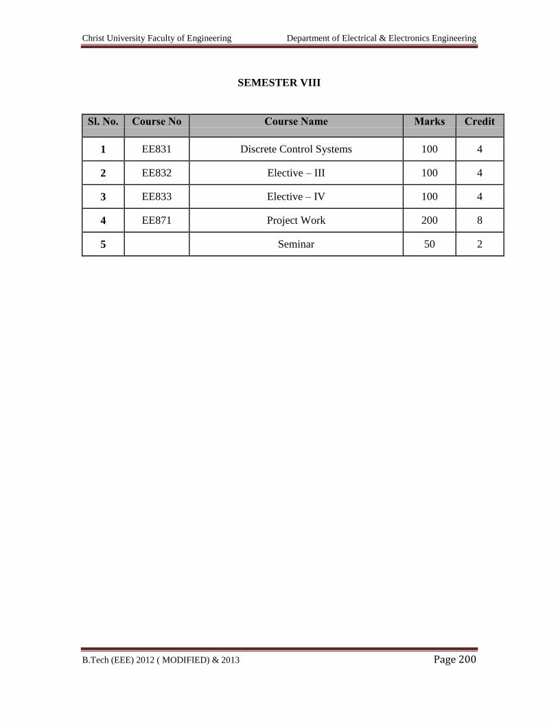
Christ University Faculty of Engineering Department of Electrical & Electronics Engineering
B.Tech (EEE) 2012 ( MODIFIED) & 2013 Page 200
SEMESTER VIII
Sl. No. Course No Course Name Marks Credit
1 EE831 Discrete Control Systems 100 4
2 EE832 Elective – III 100 4
3 EE833 Elective – IV 100 4
4 EE871 Project Work 200 8
5 Seminar 50 2
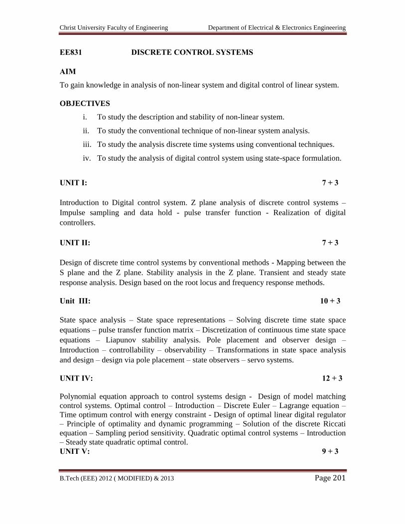
Christ University Faculty of Engineering Department of Electrical & Electronics Engineering
B.Tech (EEE) 2012 ( MODIFIED) & 2013 Page 201
EE831 DISCRETE CONTROL SYSTEMS
AIM
To gain knowledge in analysis of non-linear system and digital control of linear system.
OBJECTIVES
i. To study the description and stability of non-linear system.
ii. To study the conventional technique of non-linear system analysis.
iii. To study the analysis discrete time systems using conventional techniques.
iv. To study the analysis of digital control system using state-space formulation.
UNIT I: 7 + 3
Introduction to Digital control system. Z plane analysis of discrete control systems –
Impulse sampling and data hold - pulse transfer function - Realization of digital
controllers.
UNIT II: 7 + 3
Design of discrete time control systems by conventional methods - Mapping between the
S plane and the Z plane. Stability analysis in the Z plane. Transient and steady state
response analysis. Design based on the root locus and frequency response methods.
Unit III: 10 + 3
State space analysis – State space representations – Solving discrete time state space
equations – pulse transfer function matrix – Discretization of continuous time state space
equations – Liapunov stability analysis. Pole placement and observer design –
Introduction – controllability – observability – Transformations in state space analysis
and design – design via pole placement – state observers – servo systems.
UNIT IV: 12 + 3
Polynomial equation approach to control systems design - Design of model matching
control systems. Optimal control – Introduction – Discrete Euler – Lagrange equation –
Time optimum control with energy constraint - Design of optimal linear digital regulator
– Principle of optimality and dynamic programming – Solution of the discrete Riccati
equation – Sampling period sensitivity. Quadratic optimal control systems – Introduction
– Steady state quadratic optimal control.
UNIT V: 9 + 3
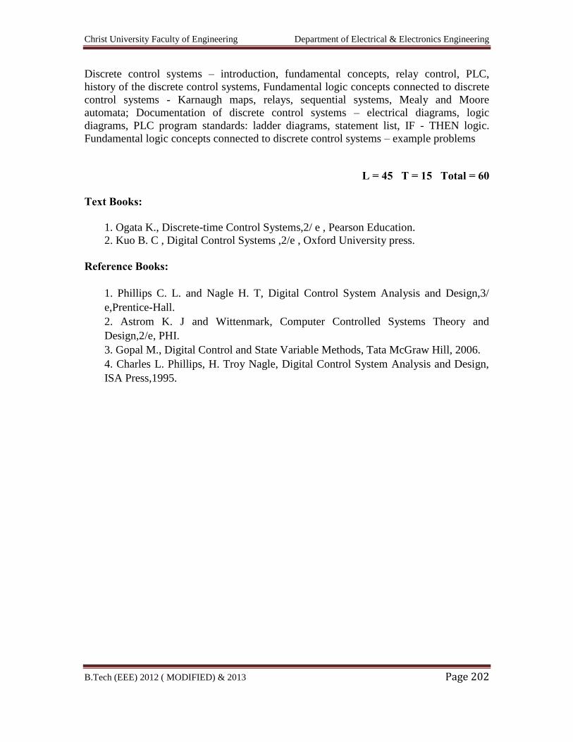
Christ University Faculty of Engineering Department of Electrical & Electronics Engineering
B.Tech (EEE) 2012 ( MODIFIED) & 2013 Page 202
Discrete control systems – introduction, fundamental concepts, relay control, PLC,
history of the discrete control systems, Fundamental logic concepts connected to discrete
control systems - Karnaugh maps, relays, sequential systems, Mealy and Moore
automata; Documentation of discrete control systems – electrical diagrams, logic
diagrams, PLC program standards: ladder diagrams, statement list, IF - THEN logic.
Fundamental logic concepts connected to discrete control systems – example problems
L = 45 T = 15 Total = 60
Text Books:
1. Ogata K., Discrete-time Control Systems,2/ e , Pearson Education.
2. Kuo B. C , Digital Control Systems ,2/e , Oxford University press.
Reference Books:
1. Phillips C. L. and Nagle H. T, Digital Control System Analysis and Design,3/
e,Prentice-Hall.
2. Astrom K. J and Wittenmark, Computer Controlled Systems Theory and
Design,2/e, PHI.
3. Gopal M., Digital Control and State Variable Methods, Tata McGraw Hill, 2006.
4. Charles L. Phillips, H. Troy Nagle, Digital Control System Analysis and Design,
ISA Press,1995.
Christ University Faculty of Engineering Department of Electrical & Electronics Engineering
B.Tech (EEE) 2012 ( MODIFIED) & 2013 Page 203
ELECTIVES
FIBRE OPTICS AND LASER INSTRUMENTS
AIM
To contribute to the knowledge of Fibre optics and Laser Instrumentation and its
Industrial & Medical Application.
OBJECTIVES
i. To expose the students to the basic concepts of optical fibers and their properties.
ii. To provide adequate knowledge about the Industrial applications of optical fibers.
iii. To expose the students to the Laser fundamentals.
iv. To provide adequate knowledge about Industrial application of lasers.
v. To provide adequate knowledge about holography & Medical applications of
Lasers.
UNIT I: OPTICAL FIBRES AND THEIR PROPERTIES 12 + 3
Principles of light propagation through a fibre - Different types of fibres and their
properties, fibre characteristics – Absorption losses – Scattering losses – Dispersion –
Connectors & splicers – Fibre termination – Optical sources – Optical detectors.
UNIT II: INDUSTRIAL APPLICATION OF OPTICAL FIBRES 9 + 3
Fibre optic sensors – Fibre optic instrumentation system – Different types of modulators
– Interferometric method of measurement of length – Moire fringes – Measurement of
pressure, temperature, current, voltage, liquid level and strain.
UNIT III: LASER FUNDAMENTALS 9 + 3
Fundamental characteristics of lasers – Three level and four level lasers – Properties of
laser – Laser modes – Resonator configuration – Q-switching and mode locking – Cavity
damping – Types of lasers – Gas lasers, solid lasers, liquid lasers, semiconductor lasers.
UNIT IV: INDUSTRIAL APPLICATION OF LASERS 6 + 3
Laser for measurement of distance, length, velocity, acceleration, current, voltage and
atmospheric effect – Material processing – Laser heating, welding, melting and trimming
of material – Removal and vaporization.
UNIT V: HOLOGRAM AND MEDICAL APPLICATIONS 9 + 3
Christ University Faculty of Engineering Department of Electrical & Electronics Engineering
B.Tech (EEE) 2012 ( MODIFIED) & 2013 Page 204
Holography – Basic principle - Methods – Helographic interferometry and application,
Holography for non-destructive testing – Holographic components – Medical
applications of lasers, laser and tissue interactive – Laser instruments for surgery,
removal of tumours of vocal cards, brain surgery, plastic surgery, gynaecology and
oncology.
L = 45 T = 15 Total = 60
TEXT BOOKS
1. J.M. Senior, ‘Optical Fibre Communication – Principles and Practice’, Prentice
Hall of India, 1985.
2. J. Wilson and J.F.B. Hawkes, ‘Introduction to Opto Electronics’, Prentice Hall of
India, 2001.
REFERENCE BOOKS
1. Donald J.Sterling Jr, ‘Technicians Guide to Fibre Optics’, 3rd Edition, Vikas
Publishing House, 2000.
2. M. Arumugam, ‘Optical Fibre Communication and Sensors’, Anuradha
Agencies, 2002.
3. John F. Read, ‘Industrial Applications of Lasers’, Academic Press, 1978.
4. Monte Ross, ‘Laser Applications’, McGraw Hill, 1968
5. G. Keiser, ‘Optical Fibre Communication’, McGraw Hill, 1995.
6. Mr. Gupta, ‘Fiber Optics Communication’, Prentice Hall of India, 2004.
Christ University Faculty of Engineering Department of Electrical & Electronics Engineering
B.Tech (EEE) 2012 ( MODIFIED) & 2013 Page 205
ADVANCED POWER ELECTRONICS
Unit I AC Voltage Controllers:
Principle of On-Off Control, Principle of Phase control, Single Phase Bi-directional
Controllers with Resistive Loads, Single Phase Controllers with Inductive Loads, Three
Phase full wave AC controllers, AC Voltage Controller with PWM Control.
Unit 2: Inverters
Principle of Operation, Single-phase bridge inverters, Three phase bridge Inverters: 180
and 120 degree of conduction. Voltage control of Single Phase and Three Phase
Inverters, Current Source Inverters, Harmonics and its reduction techniques.
Units III Cycloconverters
Basic principle of operation, single phase to single phase, threephase to three-phase and
three phase to single phase cycloconverters. Output equation, Control circuit.
Units IV-DC Power Supplies
Switched Mode DC Power Supplies, flyback converter, forward converter, half and full
bridge converter, resonant DC power supplies, bidirectional power supplies.
Units V-AC Power Supplies
Switched mode power supplies, Resonant AC power supplies, bidirectional AC power
supplies. Multistage conversions, Control Circuits: Voltage Mode Control, Current Mode
Control
Reference
1. R. S. Ramshaw, “Power Electronics Semiconductor Switches”, Champman &
Hall, 1993.
2. N. Mohan, T. M. Undeland and W. P. Robbins, “Power Electronics, Converter,
Application and Design”, Third Edition, John Willey & Sons, 2004.
3. M. H. Rashid, “Power Electronics, circuits, Devices and Applications”, Pearson,
2002, India.
4. K. Billings, “Switch Mode Power Supply Handbook”, McGraw-Hill, 1999,
Boston.
5. A. I. Pressman, “Switch Mode Power Supply Design”, McGraw-Hill, 1999, New
York.
6. N. G. Hingorani and L. Gyugyi, “Understanding FACTS”, IEEE Press, Delhi,
2001.
Christ University Faculty of Engineering Department of Electrical & Electronics Engineering
B.Tech (EEE) 2012 ( MODIFIED) & 2013 Page 206
7. B. K. Bose, “Power Electronics and Variable Frequency Drive”, Standard
Publishers Distributors, 2000.
8. Bin Wu, “High-Power Converters and AC Drives”, IEEE Press, A John Wiley &
Sons, Inc Publication, New York, 2006.
9. G. T. Heydt, “Electric Power Quality”, Stars in a Circle Publications, second
edition, 1994, Avarua, Rarotonga, Cook Islands.
10. R. C. Duagan, M. F. Mcgranaghan and H. W. Beaty, “Electric Power System
Quality”, McGraw-Hill, 2001, 1221 Avenue of the Americas, New York.
11. Vijay K. Sood, “HVDC and FACTS Controllers - Applications of Static
Converters in Power Systems”, Kluwer Academic Publishers, Masachusetts,
2004.
12. J. Arrillaga, Y. H. Liu and N. R. Waston, “Flexible Power Transmission-The
HVDC Options”, John Wiley & Sons, Ltd, Chichester, UK, 2007.
Christ University Faculty of Engineering Department of Electrical & Electronics Engineering
B.Tech (EEE) 2012 ( MODIFIED) & 2013 Page 207
ADVANCED CONTROL SYSTEMS
AIM
To gain knowledge in analysis of non-linear system and digital control of linear system.
OBJECTIVES
To study the description and stability of non-linear system.
To study the conventional technique of non-linear system analysis.
To study the analysis discrete time systems using conventional techniques.
To study the analysis of digital control system using state-space formulation.
To study the formulation and analysis of multi input multi output (MIMO) system.
UNIT I: NON-LINEAR SYSTEM – DESCRIPTION & STABILITY 9 + 3
Linear vs non-linear – Examples – Incidental and Intentional – Mathematical description
- Equilibria and linearisation - Stability – Lyapunov function – Construction of Lyapunov
function.
UNIT II: PHASE PLANE AND DESCRIBING FUNCTION ANALYSIS 9 + 3
Construction of phase trajectory – Isocline method – Direct or numerical integration –
Describing function definition – Computation of amplitude and frequency of oscillation.
UNIT III: Z-TRANSFORM AND DIGITAL CONTROL SYSTEM 9 + 3
Z transfer function – Block diagram – Signal flow graph – Discrete root locus – Bode
plot.
UNIT IV: STATE-SPACE DESIGN OF DIGITAL CONTROL SYSTEM 9 + 3
State equation – Solutions – Realization – Controllability – Observability – Stability –
Jury’s test.
UNIT V: MUTLI INPUT MULTI OUTPUT (MIMO) SYSTEM 9 + 3
Models of MIMO system – Matrix representation – Transfer function representation –
Poles and Zeros – Decoupling – Introduction to multivariable Nyquist plot and singular
values analysis – Model predictive control.
TEXT BOOKS
1. Benjamin C. Kuo, ‘Digital Control Systems’, Oxford University Press, 1992.
Christ University Faculty of Engineering Department of Electrical & Electronics Engineering
B.Tech (EEE) 2012 ( MODIFIED) & 2013 Page 208
2. George J. Thaler, ‘Automatic Control Systems’, Jaico Publishers, 1993.
REFERENCE BOOKS
1. I.J. Nagrath and M. Gopal, ‘Control Systems Engineering’, New Age
International Publishers, 2003.
2. Raymond T. Stefani & Co., ‘Design of feed back Control systems’, Oxford
University, 2002.
3. William L. Luyben and Michael L. Luyben, ‘Essentials of Process Control’,
McGraw Hill International Editions, Chemical Engineering Series, 1997.
Christ University Faculty of Engineering Department of Electrical & Electronics Engineering
B.Tech (EEE) 2012 ( MODIFIED) & 2013 Page 209
EI 1351 BIO–MEDICAL INSTRUMENTATION
AIM
The course is designed to make the student acquire an adequate knowledge of the
physiological systems of the human body and relate them to the parameters that have
clinical importance. The fundamental principles of equipment that are actually in use at
the present day are introduced.
OBJECTIVES
i. To provide an acquaintance of the physiology of the heart, lung, blood circulation
and circulation respiration. Methods of different transducers used.
ii. To introduce the student to the various sensing and measurement devices of
electrical origin.
iii. To provide the latest ideas on devices of non-electrical devices.
iv. To bring out the important and modern methods of imaging techniques.
v. To provide latest knowledge of medical assistance / techniques and therapeutic
equipments.
UNIT I: PHYSIOLOGY AND TRANSDUCERS 9 + 3
Cell and its structure – Action and resting – Potential propagation of action potential –
Sodium pump – Nervous system – CNS – PNS – Nerve cell – Synapse – Cardio
pulmonary system – Physiology of heart and lungs – Circulation and respiration –
Transducers – Different types – Piezo-electric, ultrasonic, resistive, capacitive, inductive
transducers – Selection criteria.
UNIT II: ELECTRO – PHYSIOLOGICAL MEASUREMENTS 9 + 3
Basic components of a biomedical system – Electrodes – Micro, needle and surface
electrodes – Amplifiers – Preamplifiers, differential amplifiers, chopper amplifiers –
Isolation amplifier.
ECG – EEG – EMG – ERG – Lead systems and recording methods – Typical waveforms.
UNIT III: NON-ELECTRICAL PARAMETER MEASUREMENTS 9 + 3
Measurement of blood pressure – Cardiac output – Cardiac rate – Heart sound –
Respiratory rate – Gas volume – Flow rate of Co2, o2 in exhaust air - PH of blood, ESR,
GSR measurements – Plethysmography.
Christ University Faculty of Engineering Department of Electrical & Electronics Engineering
B.Tech (EEE) 2012 ( MODIFIED) & 2013 Page 210
UNIT IV: MEDICAL IMAGING AND PMS 9 + 3
X-ray machine - Radio graphic and fluoroscopic techniques – Computer tomography –
MRI – Ultrasonography – Endoscopy – Thermography – Different types of biotelemetry
systems and patient monitoring – Electrical safety.
UNIT V: ASSISTING AND THERAPEUTIC EQUIPMENTS 9 + 3
Pacemakers – Defibrillators – Ventilators – Nerve and muscle stimulators – Diathermy –
Heart – Lung machine – Audio meters – Dializers.
L = 45 T = 15 Total = 60
TEXT BOOKS
1. Leslie Cromwell, Fred J.Weibell, Erich A.Pfeiffer, ‘Bio-Medical Instrumentation
and Measurements’, II Edition, Pearson Education, 2002 / PHI.
2. R.S.Khandpur, ‘Handbook of Bio-Medical instrumentation’, Tata McGraw Hill
Publishing Co Ltd., 2003.
REFERENCE BOOKS
1. M.Arumugam, ‘Bio-Medical Instrumentation’, Anuradha Agencies, 2003.
2. L.A. Geddes and L.E.Baker, ‘Principles of Applied Bio-Medical
Instrumentation’, John Wiley & Sons, 1975.
3. J.Webster, ‘Medical Instrumentation’, John Wiley & Sons, 1995.
4. C.Rajarao and S.K. Guha, ‘Principles of Medical Electronics and Bio-medical
Instrumentation’, Universities press (India) Ltd, Orient Longman ltd, 2000.
Christ University Faculty of Engineering Department of Electrical & Electronics Engineering
B.Tech (EEE) 2012 ( MODIFIED) & 2013 Page 211
CS 1032 ARTIFICIAL INTELLIGENCE AND EXPERT SYSTEMS
AIM
To present the concepts of intelligent agents, searching, knowledge and reasoning,
planning, learning and expert systems.
OBJECTIVES
i. To study the idea of intelligent agents and search methods.
ii. To study about representing knowledge.
iii. To study the reasoning and decision making in uncertain world.
iv. To construct plans and methods for generating knowledge.
v. To study the concepts of expert systems.
UNIT I: INTRODUCTION 9 + 3
Introduction to AI: Intelligent agents – Perception – Natural language processing –
Problem – Solving agents – Searching for solutions: Uniformed search strategies –
Informed search strategies.
UNIT II: KNOWLEDGE AND REASONING 9 + 3
Adversarial search – Optimal and imperfect decisions – Alpha, Beta pruning – Logical
agents: Propositional logic – First order logic – Syntax and semantics – Using first order
logic – Inference in first order logic.
UNIT III: UNCERTAIN KNOWLEDGE AND REASONING 8 + 3
Uncertainty – Acting under uncertainty – Basic probability notation – Axioms of
probability – Baye’s rule – Probabilistic reasoning – Making simple decisions.
UNIT IV: PLANNING AND LEARNING 9 + 3
Planning: Planning problem – Partial order planning – Planning and acting in non-
deterministic domains – Learning: Learning decision trees – Knowledge in learning –
Neural networks – Reinforcement learning – Passive and active.
UNIT V: EXPERT SYSTEMS 10 + 3
Definition – Features of an expert system – Organization – Characteristics – Prospector –
Knowledge Representation in expert systems – Expert system tools – MYCIN –
EMYCIN.
L = 45 T = 15 Total = 60
Christ University Faculty of Engineering Department of Electrical & Electronics Engineering
B.Tech (EEE) 2012 ( MODIFIED) & 2013 Page 212
TEXT BOOKS
1. Stuart Russel and Peter Norvig, ‘Artificial Intelligence A Modern Approach’,
Second Edition, Pearson Education, 2003 / PHI.
2. Donald A.Waterman, ‘A Guide to Expert Systems’, Pearson Education.
REFERENCE BOOKS
1. George F.Luger, ‘Artificial Intelligence – Structures and Strategies for Complex
Problem Solving’, Fourth Edition, Pearson Education, 2002.
2. Elain Rich and Kevin Knight, ‘Artificial Intelligence’, Second Edition Tata
McGraw Hill, 1995.
3. Janakiraman, K.Sarukesi, ‘Foundations of Artificial Intelligence and Expert
Systems’, Macmillan Series in Computer Science.
4. W. Patterson, ‘Introduction to Artificial Intelligence and Expert Systems’,
Prentice Hall of India, 2003.
Christ University Faculty of Engineering Department of Electrical & Electronics Engineering
B.Tech (EEE) 2012 ( MODIFIED) & 2013 Page 213
CS 1033 DATA COMMUNICATION AND NETWORKS
AIM
To study the details regarding communication of voice and video, networks and its
functions, data conversions, controlling of errors, switching information and its devices,
internetworking device and different layers of TCP/IP.
OBJECTIVES
i. To study about the physical arrangement of networks, types and modes of
networks, data conversions and transmission medium.
ii. To study the detection and correction of errors, link control and link
protocols of data link layer.
iii. To study the access method, electrical specification and implementation of
different networks, types of switching.
iv. To study about the standardized data interface and it’s working principle.
v. To study the logic of link mechanisms used in networks and different
layers of TCP/IP.
UNIT I: DATA COMMUNICATION 9 + 3
Introduction: Networks – Protocols and standards – Standards organizations – Line
configurations – Topology – Transmission mode – Categories of networks – Inter
networks.
OSI model: Functions of the layers.
Encoding and modulating: Digital-to-digital conversion – Analog-to-digital conversion –
Digital-to-analog conversion – Analog-to-analog conversion.
Transmission media: Guided media – Unguided media – Transmission impairment –
Performance.
UNIT II: ERROR CONTROL AND DATA LINK PROTOCOLS 9 + 3
Error detection and correction: Types of errors – Detection – Vertical Redundancy Check
(VRC) – Longitudinal Redundancy Check (LRC) – Cyclic Redundancy Check (CRC) –
Check sum – Error correction.
Data link control: Line discipline – Flow control – Error control.
Data link protocols: Asynchronous protocols – Synchronous protocols – Character
oriented protocols – BIT oriented protocols – Link access procedures.
UNIT III: NETWORKS AND SWITCHING 9 + 3
LAN: Project 802 – Ethernet – Token bus – Token ring – FDDI.
Christ University Faculty of Engineering Department of Electrical & Electronics Engineering
B.Tech (EEE) 2012 ( MODIFIED) & 2013 Page 214
MAN: IEEE 802.6 (DQDB) – SMDS.
Switching: Circuit switching – Packet switching – Message switching.
UNIT IV: X.25, FRAME RELAY, ATM AND SONET/ SDH 9 + 3
X.25: X.25 Layers.
Frame relay: Introduction – Frame relay operation – Frame relay layers – Congestion
control – Leaky bucket algorithm – Traffic control.
ATM: Design goals – ATM architecture – ATM layers – ATM applications.
SONET / SDH: Synchronous transport signals – Physical configuration – SONET layers
– Applications.
UNIT V: NETWORKING DEVICES AND TCP / IP PROTOCOL SUITE 9 + 3
Networking and internetworking devices: Repeaters – Bridges – Gateways – Other
devices – Routing algorithms – Distance vector routing – Link state routing.
TCP / IP protocol suite: Overview of TCP/IP.
Network layers: Addressing – Subnetting – Other protocols and network layers.
Application layer: Domain Name System (DNS) – Telnet – File Transfer Protocol (FTP)
– Trivial File Transfer Protocol (TFTP) – Simple Mail Transfer Protocol (SMTP) –
Simple Network Management Protocol (SNMP).
L = 45 T = 15 Total = 60
TEXT BOOK
1. Behrouz A.Forouzan, ‘Data Communication and Networking’, Second Edition,
Tata McGraw Hill, 2000.
REFERENCE BOOKS
1. William Stallings, ‘Data and Computer Communication’, 8th Edition, Pearson
Education, 2003 / PHI.
2. Andrew Tannenbaum.S. ‘Computer Networks’, Pearson Education, 4th Edition,
2003 / PHI.
Christ University Faculty of Engineering Department of Electrical & Electronics Engineering
B.Tech (EEE) 2012 ( MODIFIED) & 2013 Page 215
EE 1002 POWER SYSTEM DYNAMICS
AIM
To become familiar with the modelling of components and system for carrying out
transient and dynamic stability analysis of large scale power system.
OBJECTIVES
i. To study detailed modeling of synchronous machine and its excitation and
speed-governing controllers.
ii. To study transient stability simulation of multimachine power system.
iii. To study small signal stability analysis of a single-machine infinite bus
system with excitation system and power system stabilizer.
UNIT I: INTRODUCTION 4 + 3
Concept and importance of stability in power system operation and design; distinction
between transient and dynamic stability; complexity of stability problem in large system:
Need for reduced models; stability of interconnected systems.
UNIT II: MACHINE MODELLING 12 + 3
Park’s transformation; flux linkage equations, current space model, per Unit conversion,
normalizing the equations, equivalent circuit, flux linkage state space model, sub
transient and transient inductances and time constants. Simplified models (one axis and
constant flux linkage), steady state equations and phasor diagrams.
UNIT III: MACHINE CONTROLLERS 9 + 3
Exciter and voltage regulators, function of excitation systems, types of excitation
systems, typical excitation system configuration, block diagram and state space
representation of IEEE type 1 excitation system, saturation function, stabilizing circuit.
Function of speed governing systems, block diagram and state space representation of
IEEE mechanical hydraulic governor and electrical hydraulic governors for hydro
turbines and steam turbines.
UNIT III: TRANSIENT STABILITY 8 + 3
State equation for multi machine simulation with one axis model, transient stability
simulation of multi machine power system with one axis machine model including
excitation system and speed governing system using R-K method of fourth order (Gill’s
technique), power system stabilizer.
Christ University Faculty of Engineering Department of Electrical & Electronics Engineering
B.Tech (EEE) 2012 ( MODIFIED) & 2013 Page 216
UNIT V: DYNAMIC STABILITY 12 + 3
System response to small disturbances: Linear model of the unregulated synchronous
machine and its modes of oscillation, regulated synchronous machine, distribution of
power impact, linearization of the load equation for the one machine problem –
Simplified linear model, effect of excitation on dynamic stability, approximate system
representation; supplementary stabilizing signals, dynamic performance measure, small
signal performance measures.
L = 45 T = 15 Total = 60
TEXT BOOKS
1. P.M. Anderson and A.A.Fouad, ‘Power System Control and Stability’, Galgotia
Publications, New Delhi, 2003.
2. P. Kundur, ‘Power System Stability and Control’, McGraw Hill Inc., USA, 1994.
REFERENCE BOOK
1. M.A.Pai and W.Sauer, ‘Power System Dynamics and Stability’, Pearson
Education Asia, India, 2002.
Christ University Faculty of Engineering Department of Electrical & Electronics Engineering
B.Tech (EEE) 2012 ( MODIFIED) & 2013 Page 217
CS 1034 COMPUTER ARCHITECTURE
AIM
i. To Study the structure and behavior of processors, memories and
input and output Units and to study their interactions.
OBJECTIVES
i. To study the various representations of data, register transfer language for
micro- operations and organization and design of a digital computer.
ii. To teach the concept of micro-programmed control Unit, the central
processing Unit, stack and instruction formats.
iii. To Study the various arithmetic operation’s algorithms and their hardware
implementations and concept of pipelining and vector processing.
iv. To illustrate the techniques to communicate with input and output devices.
v. To study the organization and operation of various memories and memory
management hardware.
UNIT I: DATA REPRESENTATION, MICRO-OPERATIONS AND
ORGANIZATION AND DESIGN 13 + 3
Data representation: Data types, complements, fixed–point representation, floating-point
representation, other binary codes, error detection codes.
Register transfer and micro operations: Register transfer language, register transfer, bus
and memory transfers, arithmetic micro-operations, logic micro-operations, shift micro-
operations, arithmetic logic shift Unit.
Basic computer organization and design: Instruction codes, computer registers, computer
instructions, timing and control, instruction cycle, memory reference instructions, input-
output and interrupt. Complete computer description, design of basic computer, design of
accumulator logic.
UNIT II: CONTROL AND CENTRAL PROCESSING UNIT 8 + 3
Micro programmed control: Control memory, address sequencing, micro-program
example, design of control Unit.
Central processing Unit: General register organization, stack organization, instruction
formats, addressing modes, data transfer and manipulation, program control, reduced
instruction set computer.
Christ University Faculty of Engineering Department of Electrical & Electronics Engineering
B.Tech (EEE) 2012 ( MODIFIED) & 2013 Page 218
UNIT III: COMPUTER ARITHMETIC, PIPELINE AND VECTOR
PROCESSING
8 + 3
Computer arithmetic: Addition and subtraction, multiplication algorithms, division
algorithms, floating-point arithmetic operations, decimal arithmetic Unit, decimal
arithmetic operations.
Pipeline and vector processing: Parallel processing, pipelining, arithmetic pipeline,
instruction pipeline, RISC pipeline, vector processing array processors.
UNIT IV: INPUT-OUTPUT ORGANIZATION 8 + 3
Input-output organization: Peripheral devices, input-output interface, asynchronous data
transfer, modes of transfer, priority interrupt, direct memory access, input-output
processor, serial communication.
UNIT V: MEMORY ORGANIZATION 8 + 3
Memory organization: Memory hierarchy, main memory, auxiliary memory, associative
memory, cache memory, virtual memory, memory management hardware.
TEXT BOOK
1. Morris Mano, ‘Computer System Architecture’, 3rd Edition, Pearson Education,
2002 / PHI.
REFERENCE BOOKS
1. Vincent P.Heuring and Harry F.Jordan, ‘Computer Systems Design and
Architecture’, Pearson Education Asia Publications, 2002.
2. John P.Hayes, ‘Computer Architecture and Organization’, Tata McGraw Hill,
1988.
3. Andrew S.Tanenbaum, ‘Structured Computer Organization’, 4th Edition, Prentice
Hall of India/Pearson Education, 2002.
4. William Stallings, ‘Computer Organization and Architecture’, 6th Edition,
Prentice Hall of India/Pearson Education, 2003.
Christ University Faculty of Engineering Department of Electrical & Electronics Engineering
B.Tech (EEE) 2012 ( MODIFIED) & 2013 Page 219
CS 1035 OPERATING SYSTEMS
AIM
To introduce the basic concepts of operating systems, process management, storage
management, I/O systems and distributed systems.
OBJECTIVES
i. To study the basic concepts of operating system, computer system structures and
operating system structures.
ii. To study about processes, threads, CPU scheduling, process synchronization and
deadlocks.
iii. To study about memory management, virtual memory, file system interface and file
system implementation.
iv. To study about I/O systems and mass-storage structure.
v. To study about distributed system structures, distributed file systems and
distributed coordination.
UNIT I: OPERATING SYSTEMS – AN OVERVIEW 8 + 3
What is an OS? – Mainframe systems – Desktop systems –Multiprocessor systems –
Distributed systems – Clustered systems – Real time systems – Handheld systems.
Computer system operation – I/O structure – Storage structure – Storage hierarchy –
Hardware protection – Network structure.
System components – Operating system services – System calls – System programs –
System structure – Virtual machines – System design and implementation – System
generation.
UNIT II: PROCESS MANAGEMENT 10 + 3
Process concept – Process scheduling – Operations on processes – Cooperating
processes – Inter process communication – Communication in client-server systems.
Threads - Overview - Multithreading models – Threading issues.
Basic concepts – Scheduling criteria – Scheduling algorithms – Multiple-processor
scheduling – Real time scheduling – Process scheduling models. The critical section
problem – Synchronization hardware – Semaphores – Classic problems of
synchronization – Critical regions – Monitors – Atomic transactions.
System model – Deadlock characterization – Methods for handling deadlocks –
Deadlock prevention – Deadlock avoidance – Deadlock detection – Recovery from
deadlock.
Christ University Faculty of Engineering Department of Electrical & Electronics Engineering
B.Tech (EEE) 2012 ( MODIFIED) & 2013 Page 220
UNIT III: STORAGE MANAGEMENT 10 + 3
Background – Swapping – Contiguous memory allocation – Paging – Segmentation –
Segmentation with Paging. Background – Demand paging – Process creation – Page
replacement – Allocation of frames – Thrashing.
File concept: Access methods – Directory structure – File system mounting – File
sharing – Protection. File system structure – File system implementation – Directory
implementation – Allocation methods – Free-space management – Efficiency and
performance – Recovery.
UNIT IV: I/O SYSTEMS 8 + 3
I/O hardware – Application I/O interface – Kernel I/O subsystem – Transforming I/O to
hardware operations – Streams – Performance.
Disk structure – Disk scheduling – Disk management – Swap-space management –
RAID structure – Disk attachment – Stable – Storage implementation – Tertiary storage
structure.
UNIT V: DISTRIBUTED SYSTEMS 9 + 3
Background – Topology – Network types – Communication – Communication protocols
– Robustness – Design issues. Naming and transparency – Remote file access – Stateful
versus stateless service – File replication.
Event ordering – Mutual exclusion – Atomicity – Concurrency control – Deadlock
handling – Election algorithms – Reaching agreement.
L = 45 T=15 Total = 60
TEXT BOOK
1. Abraham Silberschatz, Peter Baer Galvin and Greg Gagne, ‘Operating System
Concepts’, Sixth Edition, Windows XP update, John Wiley & Sons (ASIA) Pvt. Ltd,
2002.
REFERENCE BOOKS
1. Harvey M. Deitel, ‘Operating Systems’, Second Edition, Pearson Education Pvt. Ltd.,
2002.
2. Andrew S. Tanenbaum, ‘Modern Operating Systems’, 2nd Edition, Pearson Education,
2000 / PHI.
3. William Stallings, ‘Operating System’, Pearson Education, 4th Edition, 2003 / PHI.
Christ University Faculty of Engineering Department of Electrical & Electronics Engineering
B.Tech (EEE) 2012 ( MODIFIED) & 2013 Page 221
CS 1036 INTERNETWORKING TECHNOLOGY
AIM
To present the concepts of Networking, Internetworking, IP protocol, TCP
protocol and Internet applications
OBJECTIVES
i. To study the basic concepts of networking.
ii. To study about interconnection of networks.
iii. To study the IP protocol and it’s routing.
iv. To introduce the TCP protocol.
v. To study the Internet applications and security.
UNIT I: COMPUTER NETWOKS 9 + 3
Introduction to networks – Network topology – Types of networks – Network
architecture – Layering – Design issues – Client/Server model – Protocols – Bridges –
Routers – Repeaters – Switches.
UNIT II: BASICS OF INTERNETWORKING 9 + 3
Introduction to internetworking – Internetworking concepts and architectural model –
Internet addressing – Domain Name System (DNS) – Address Resolution Protocol (ARP)
– Reverse Address Resolution Protocol (RARP).
UNIT III: INTERNET PROTOCOL AND ITS ROUTING 9 + 3
Introduction to IP protocol – Virtual networks – Concept of unreliable delivery –
Connectionless delivery system – Purpose on internet protocol – Internet data gram –
Data gram options.
Introduction to routing - IP data gram – Direct and indirect delivery- Table driven IP
routing – Next hop routing.
UNIT IV: TRANSMISSION CONTROL PROTOCOL 9 + 3
Introduction to TCP – Properties of reliable delivery service – TCP protocol – TCP
segment format – TCP connection – TCP state machine – Silly window syndrome.
Christ University Faculty of Engineering Department of Electrical & Electronics Engineering
B.Tech (EEE) 2012 ( MODIFIED) & 2013 Page 222
UNIT V: INTERNETWOKING APPLICATIONS 9 + 3
Simple Mail Transfer Protocol (SMTP) - Post Office Protocol (POP) - File Transfer
Protocol (FTP) – Telnet – Simple Network Management Protocol (SNMP) – Internet
security and firewall design.
L = 45 T = 15 Total = 60
TEXT BOOKS
1. Douglas E. Comer, ‘Internetworking with TCP/IP Volume 1’, Third Edition,
Prentice Hall, 2001.
2. Andrew S.Tananbaum, ‘Computer Networks’, Fourth Edition, Prentice Hall of
India/Pearson Education, 2003.
REFERENCE BOOKS
1. Bechrouz A. Forouzan, ‘TCP/IP Protocol Suite’, Second Edition, Tata McGraw
Hill, 2000.
2. William Stallings, ‘Data and Computer Communications’, Seventh Edition,
Prentice Hall of India/Pearson Education, 2003.
Christ University Faculty of Engineering Department of Electrical & Electronics Engineering
B.Tech (EEE) 2012 ( MODIFIED) & 2013 Page 223
EC 1032 EMBEDDED SYSTEM DESIGN
AIM
To introduce to the functional building blocks of an embedded system for developing a
real time system application.
OBJECTIVES
i. Introduce to features that build an embedded system.
ii. To help the understanding of the interaction that the various components
within an embedded system have with each other.
iii. Techniques of inter facing between processors & peripheral device related
to embedded processing.
iv. To enable writing of efficient programs on any dedicated processor.
v. To present in lucid manner the basic concepts of systems programming
like operating system, assembler compliers etc and to understand the
management task needed for developing embedded system.
UNIT I: INTRODUCTION TO EMBEDDED SYSTEM 9 + 3
Introduction to functional building blocks of embedded systems – Register, memory
devices, ports, timer, interrupt controllers using circuit block diagram representation for
each categories.
UNIT II: PROCESSOR AND MEMORY ORGANIZATION 6 + 3
Structural Units in a processor; selection of processor & memory devices; shared
memory; DMA; interfacing processor, memory and I/O Units; memory management –
Cache mapping techniques, dynamic allocation - Fragmentation.
UNIT III: DEVICES & BUSES FOR DEVICES NETWORK 9 + 3
I/O devices; timer & counting devices; serial communication using I2C, CAN, USB
buses; parallel communication using ISA, PCI, PCI/X buses, arm bus; interfacing with
devices/ports, device drivers in a system – Serial port & parallel port.
UNIT IV: I/O PROGRAMMING SCHEDULE MECHANISM 12 + 3
Intel I/O instruction – Transfer rate, latency; interrupt driven I/O - Non-maskable
interrupts; software interrupts, writing interrupt service routine in C & assembly
languages; preventing interrupt overrun; disability interrupts.
Multi threaded programming – Context switching, premature & non-premature
multitasking, semaphores.
Christ University Faculty of Engineering Department of Electrical & Electronics Engineering
B.Tech (EEE) 2012 ( MODIFIED) & 2013 Page 224
Scheduling – Thread states, pending threads, context switching, round robin scheduling,
priority based scheduling, assigning priorities, deadlock, watch dog timers.
UNIT V: REAL TIME OPERATING SYSTEM (RTOS) 9 + 3
Introduction to basic concepts of RTOS, Basics of real time & embedded system
operating systems, RTOS – Interrupt handling, task scheduling; embedded system design
issues in system development process – Action plan, use of target system, emulator, use
of software tools.
L = 45 T = 15 Total = 60
TEXT BOOKS
1. Rajkamal, ‘Embedded System – Architecture, Programming, Design’, Tata
McGraw Hill, 2003.
2. Daniel W. Lewis ‘Fundamentals of Embedded Software’, Prentice Hall of India,
2004.
REFERENCE BOOKS
1. David E. Simon, ‘An Embedded Software Primer’, Pearson Education, 2004.
2. Frank Vahid, ‘Embedded System Design – A Unified Hardware & Software
Introduction’, John Wiley, 2002.
3. Sriram V. Iyer, Pankaj Gupte, ‘Embedded Real Time Systems Programming’,
Tata McGraw Hill, 2004.
4. Steve Heath, ‘Embedded System Design’, II edition, Elsevier, 2003.
Christ University Faculty of Engineering Department of Electrical & Electronics Engineering
B.Tech (EEE) 2012 ( MODIFIED) & 2013 Page 225
IC 1002 ADAPTIVE CONTROL
AIM
To gain knowledge on adaptive control of systems through parameter
Identification and controller retuning.
OBJECTIVES
i. To study the definition of adaptive control and methods of adaptation.
ii. To study the parameter identification of systems.
iii. To study the self-tuning of PID controllers based on parameter identification.
iv. To study the model reference adaptive control.
v. To study the practical application through case studies.
UNIT I: INTRODUCTION 9 + 3
Introduction to adaptive control - Effects of process variations – Adaptive control
schemes – Adaptive control problem – Non-parametric identification – Step response
method – Impulse response method – Frequency response method.
UNIT II: PARAMETRIC IDENTIFICATION 9 + 3
Linear in parameter models - ARX – ARMAX – ARIMAX – Least square estimation –
Recursive least square estimation – Extended least square estimation – Maximum
likelihood estimation – Introduction to non-linear systems identification - Pseudo
random binary sequence.
UNIT III: SELF-TUNING REGULATOR 9 + 3
Deterministic in-direct self-tuning regulators – Deterministic direct self-tuning regulators
– Introduction to stochastic self-tuning regulators – Stochastic indirect self-tuning
regulator.
UNIT IV: MODEL REFERENCE ADAPTIVE CONTROLLER 9 + 3
The MIT rule – Lyapunov theory – Design of model reference adaptive controller using
MIT rule and Lyapunov theory – Relation between model reference adaptive controller
and self-tuning regulator.
UNIT V: TUNING OF CONTROLLERS AND CASE STUDIES 9 + 3
Design of gain scheduling controller - Auto-tuning of PID regulator – Stability analysis
of adaptive controllers – Application of adaptive control in chemical reactor, distillation
column and variable area tank system.
Christ University Faculty of Engineering Department of Electrical & Electronics Engineering
B.Tech (EEE) 2012 ( MODIFIED) & 2013 Page 226
TEXT BOOK
1. Karl J. Astrom & Bjorn Wittenmark, ‘Adaptive Control’, Pearson Education
(Singapore), Second Edition, 2003.
REFERENCE BOOKS
1. T. C.H.A. Hsia, ‘System Identification’, Lexington books, 1974.
2. Stephanopoulis G. ‘Chemical Process Control’, Prentice Hall of India, New Delhi,
1990.
Christ University Faculty of Engineering Department of Electrical & Electronics Engineering
B.Tech (EEE) 2012 ( MODIFIED) & 2013 Page 227
EE 1004 POWER QUALITY
AIM
To study the various issues affecting Power Quality, their production, monitoring and
suppression.
OBJECTIVES
i. To study the production of voltages sags, over voltages and harmonics and
methods of control.
ii. To study various methods of power quality monitoring.
UNIT I: INTRODUCTION TO POWER QUALITY 3 + 3
Terms and definitions: Overloading, under voltage, sustained interruption; sags and
swells; waveform distortion, Total Harmonic Distortion (THD), Computer Business
Equipment Manufacturers Associations (CBEMA) curve.
UNIT II: VOLTAGE SAGS AND INTERRUPTIONS 7 + 3
Sources of sags and interruptions, estimating voltage sag performance, motor starting
sags, estimating the sag severity, mitigation of voltage sags, active series compensators,
static transfer switches and fast transfer switches.
UNIT III: OVERVOLTAGES 10 + 3
Sources of over voltages: Capacitor switching, lightning, ferro resonance; mitigation of
voltage swells: Surge arresters, low pass filters, power conditioners – Lightning
protection, shielding, line arresters, protection of transformers and cables, computer
analysis tools for transients, PSCAD and EMTP.
UNIT IV: HARMONICS 12 + 3
Harmonic distortion: Voltage and current distortion, harmonic indices, harmonic sources
from commercial and industrial loads, locating harmonic sources; power system response
characteristics, resonance, harmonic distortion evaluation, devices for controlling
harmonic distortion, passive filters, active filters, IEEE and IEC standards.
UNIT V: POWER QUALITY MONITORING 13 + 3
Monitoring considerations: Power line disturbance analyzer, per quality measurement
equipment, harmonic / spectrum analyzer, flicker meters, disturbance analyzer,
applications of expert system for power quality monitoring.
Christ University Faculty of Engineering Department of Electrical & Electronics Engineering
B.Tech (EEE) 2012 ( MODIFIED) & 2013 Page 228
REFERENCE BOOKS
1. Roger. C Dugan, Mark. F. McGranagham, Surya Santoso, H. Wayne Beaty,
‘Electrical Power Systems Quality’ McGraw Hill, 2003.
2. PSCAD User Manual.
Christ University Faculty of Engineering Department of Electrical & Electronics Engineering
B.Tech (EEE) 2012 ( MODIFIED) & 2013 Page 229
EE 1006 OPERATIONS RESEARCH
AIM
To expose the students to the techniques and modeling concepts needed to analyze and
design complex systems.
OBJECTIVE
The objective of the course is to enable a student to learn aspects of operations research
covering Linear Programming, Assignment and Transportation models, PERT & CPM
techniques, Queuing and Game theory and integer programming.
UNIT – I 9 + 3
Operations Research Models – Operations Research Techniques – Art of Modeling –
Construction of LP Model – Graphical LP solution – Graphical Sensitivity Analysis –
The Simplex Algorithm – The M- method – The two phase method – degeneracy –
Alternative optima – unbounded solutions – infeasible solution – redundancies – LP
packages.
UNIT – II 9 + 3
Definition of the Dual problem – primal-dual relationship – Economic interpretation of
duality – Dual simplex method – primal dual computation – post optimal or sensitivity
analysis – Changes affecting feasibility – Changes affecting optimality – Revised simplex
method – LP packages.
UNIT – III 9 + 3
Definition of Transportation model – The transportation algorithm – Determination of the
starting solution – Iterative computations of the Algorithm – The Assignment Model –
The Hungarian method – The Transshipment model – Inter programming problem –
Cutting plane Algorithm.
UNIT – IV 9 + 3
Scope of Network Applications – Network solution – Minimal spanning tree Algorithm –
Shortest Route problem – Examples – Shortest Route Algorithm – Maximal flow model –
Minimum cost capacitated flow problems.
Christ University Faculty of Engineering Department of Electrical & Electronics Engineering
B.Tech (EEE) 2012 ( MODIFIED) & 2013 Page 230
UNIT – V 9 + 3
Network diagram representation – Critical path method – Time estimates – Crashing –
Time charts – PERT and CPM for project scheduling – Resource planning – Case studies.
TEXT BOOK
1.Handy A. Taha, “Operation Research – An Introduction”, 7th Edition, Pearson
Education, Asia, 2002.
REFERENCE BOOKS
1. Ronald. L. Rardin, “Optimization in Operation Research”, Person Education,
Asia, 2002.
2. JIT.S Chandran, Mahendran P. Kawatra Ki Ho Kim, “Essential of Linear
Programming”, Vikas Publishing House Pvt.Ltd., New Delhi, 1994.
3. Hiller F.S Liberman G.J, “Introduction to Operation Research”, 6th Edition,
McGraw Hill, 1995.
4. R.Panneer Selvam, “Operations Research”, Prentice Hall of India, 2002.
5. P.C. Tulsin, “Quantitative Technique : Theory and Problem”, Pearson Education,
2002.
6. Ravindran, Phillips, Solberg, “Operation Research Principles and Practice”,
Second Edition, John wiley, 1987.
Christ University Faculty of Engineering Department of Electrical & Electronics Engineering
B.Tech (EEE) 2012 ( MODIFIED) & 2013 Page 231
EE 1001 SPECIAL ELECTRICAL MACHINES
AIM
To expose the students to the construction, principle of operation and performance of
special electrical machines as an extension to the study of basic electrical machines.
OBJECTIVES
To impart knowledge on
i. Construction, principle of operation and performance of synchronous reluctance
motors.
ii. Construction, principle of operation and performance of stepping motors.
iii. Construction, principle of operation and performance of switched reluctance
motors.
iv. Construction, principle of operation and performance of permanent magnet
brushless D.C. motors.
v. Construction, principle of operation and performance of permanent magnet
synchronous motors.
UNIT I: SYNCHRONOUS RELUCTANCE MOTORS 9 + 3
Constructional features – Types – Axial and radial air gap motors – Operating principle –
Reluctance – Phasor diagram - Characteristics – Vernier motor.
UNIT II: STEPPING MOTORS 9 + 3
Constructional features – Principle of operation – Variable reluctance motor – Hybrid
motor – Single and multi stack configurations – Theory of torque predictions – Linear
and non-linear analysis – Characteristics – Drive circuits.
UNIT III: SWITCHED RELUCTANCE MOTORS 9 + 3
Constructional features – Principle of operation – Torque prediction – Power controllers
– Non-linear analysis – Microprocessor based control - Characteristics – Computer
control.
UNIT IV: PERMANENT MAGNET BRUSHLESS D.C. MOTORS 9 + 3
Principle of operation – Types – Magnetic circuit analysis – EMF and torque equations –
Power controllers – Motor characteristics and control.
Christ University Faculty of Engineering Department of Electrical & Electronics Engineering
B.Tech (EEE) 2012 ( MODIFIED) & 2013 Page 232
UNIT V: PERMANENT MAGNET SYNCHRONOUS MOTORS 9 + 3
Principle of operation – EMF and torque equations – Reactance – Phasor diagram –
Power controllers - Converter - Volt-ampere requirements – Torque speed characteristics
- Microprocessor based control.
TEXT BOOKS
1. T.J.E. Miller, ‘Brushless Permanent Magnet and Reluctance Motor Drives’,
Clarendon Press, Oxford, 1989.
2. P.P. Aearnley, ‘Stepping Motors – A Guide to Motor Theory and Practice’, Peter
Perengrinus, London, 1982.
REFERENCE BOOKS
1. T. Kenjo, ‘Stepping Motors and Their Microprocessor Controls’, Clarendon Press
London, 1984.
2. T. Kenjo and S. Nagamori, ‘Permanent Magnet and Brushless DC Motors’,
Clarendon Press, London, 1988.
Christ University Faculty of Engineering Department of Electrical & Electronics Engineering
B.Tech (EEE) 2012 ( MODIFIED) & 2013 Page 233
IC 1403 NEURAL NETWORK AND FUZZY LOGIC CONTROL
AIM
To cater the knowledge of Neural Networks and Fuzzy Logic Control and use
these for controlling real time systems.
OBJECTIVES
ii. To expose the students to the concepts of feed forward neural networks.
iii. To provide adequate knowledge about feedback neural networks.
iv. To teach about the concept of fuzziness involved in various systems. To
provide adequate knowledge about fuzzy set theory.
v. To provide comprehensive knowledge of fuzzy logic control and adaptive
fuzzy logic and to design the fuzzy control using genetic algorithm.
vi. To provide adequate knowledge of application of fuzzy logic control to real
time systems.
UNIT I: ARCHITECTURES 9 + 3
Introduction – Biological neuron – Artificial neuron – Neuron modeling – Learning rules
– Single layer – Multi layer feed forward network – Back propagation – Learning factors.
UNIT II: NEURAL NETWORKS FOR CONTROL 9 + 3
Feedback networks – Discrete time hop field networks – Transient response of
continuous time networks – Applications of artificial neural network - Process
identification – Neuro controller for inverted pendulum.
UNIT III: FUZZY SYSTEMS 9 + 3
Classical sets – Fuzzy sets – Fuzzy relations – Fuzzification – Defuzzification – Fuzzy
rules.
UNIT VI: FUZZY LOGIC CONTROL 9 + 3
Membership function – Knowledge base – Decision-making logic – Optimisation of
membership function using neural networks – Adaptive fuzzy system – Introduction to
genetic algorithm.
UNIT V: APPLICATION OF FLC 9 + 3
Fuzzy logic control – Inverted pendulum – Image processing – Home heating system –
Blood pressure during anesthesia – Introduction to neuro fuzzy controller.
Christ University Faculty of Engineering Department of Electrical & Electronics Engineering
B.Tech (EEE) 2012 ( MODIFIED) & 2013 Page 234
TEXT BOOKS
1. Jacek M. Zurada, ‘Introduction to Artificial Neural Systems’, Jaico
Publishing home, 2002.
2. Timothy J. Ross, ‘Fuzzy Logic with Engineering Applications’, Tata McGraw
Hill, 1997.
REFERENCE BOOKS
1. Laurance Fausett, Englewood cliffs, N.J., ‘Fundamentals of Neural Networks’,
Pearson Education, 1992.
2. H.J. Zimmermann, ‘Fuzzy Set Theory & its Applications’, Allied Publication
Ltd., 1996.
3. Simon Haykin, ‘Neural Networks’, Pearson Education, 2003.
4. John Yen & Reza Langari, ‘Fuzzy Logic – Intelligence Control & Information’,
Pearson Education, New Delhi, 2003.