bse 104 - physics ii experiment 03 applications on ohm's...
TRANSCRIPT

-1 / 12 – Dr. Ahmed ElShafee BSE104 - Spring 2016
BSE 104 - Physics II
Experiment 03
Applications on Ohm's
Law
# Student ID Student Name Grade (10)
1 2 3

-2 / 12 – Dr. Ahmed ElShafee BSE104 - Spring 2016
Experiment (3.1) An Incandescent Lamp is not an Ohmic Resistor
Objective In this experiment, you will study Ohm’s law by examining the I-V
characteristics oa a tungsten filament (bulb) to understand the meaning of non-ohmic devices
Theory Non-ohmic Devices
If a device behaves in a way that is NOT described by Ohm’s law, (i.e. the resistance is not constant, but changes in a way that depends on the voltage across it.) the device is said to be non-Ohmic.
In this case V versus I graph is not a straight line, but has some curvy shape. Such devices do not have a constant value of resistance and the resistance is called dynamic resistance because it is constantly changing.
Examples of such devices are tungsten filament (bulb), diode, thermistor etc....
Filament (bulb)
An incandescent light bulb with a tungsten filament has a positive temperature coefficient, and therefore has a very low initial resistance when the power is first applied.
As the temperature of the filament increases, the resistance of the filament increases also.
The temperature of the resistor increases by increasing the applied voltage, since the power dissipated as heat is increased due to the relation P = IV ,where I is the current passing through the tungsten filament and V is the voltage applied across it.

-3 / 12 – Dr. Ahmed ElShafee BSE104 - Spring 2016
Procedure Arrangement according to the illustration.
The voltage of the lamp is measured by the voltmeter (measuring range of
10 V=) at the connections A and B.
The ammeter with the measuring range of 10 mA= is used.
First the applied DC voltage is adjusted to 1 V and the switch is closed. The
current intensity indicated by the ammeter is listed. Then the other voltages
listed in the chart are applied.
The current intensity is measured and listed in the table. Watch the lamp!
The filament does not glow yet.
But at 10 V the incandescent lamp is fully lit. The amounts of resistance are
calculated from the measured quantities of the applied voltage and the
current intensity

-4 / 12 – Dr. Ahmed ElShafee BSE104 - Spring 2016
Measurements Voltage V Current intensity I Resistance R = V/I
1
5
10

-5 / 12 – Dr. Ahmed ElShafee BSE104 - Spring 2016
Experiment (3.2) Serial connection of incandescent Lamp
Objective Two lamps can be connected to a circuit in two different ways this
experiment deals with serial connections of incandescent lamps.
To calculate the bulb voltage drop, current and consumed power in case of single bulb connected to power source and in case of two bulbs connected in series
Theory
There are 2 ways to connect multiple devices to a power source (e.g. speakers to an amplifier), series and parallel.
In a series circuit, the current must flow through one device to get to the next device. This means that the rate of current flow through all devices is the same. The voltage across each device depends on its impedance/resistance of each device and the current flowing through the circuit.
When adding more components in a series circuit, the current flow decreases, if the applied voltage remains constant

-6 / 12 – Dr. Ahmed ElShafee BSE104 - Spring 2016
Procedure
Part 1: connecting single lamp and calculating consumed power
Arrangement according to the illustration.
The switch is closed and the light intensity of
The switch is opened and the PIB-lead straight
Measure voltage and current, write down results in table, then calculate the dissipated power
Record measured current and volt in table
Replace lamp1 with anther lamp2 which has the same characteristic.
Record measured current and volt in table

-7 / 12 – Dr. Ahmed ElShafee BSE104 - Spring 2016
Part 2: connecting two lamps in series and calculating consumed power
Arrangement according to the illustration.
After closing the switch it can be seen that the two lamps burn much less intensely than the single lamp used before.
Increase input voltage to 12 Volts
When the applied voltage is increased to 12Volt approximately the same light intensity as before can be achieved
Record measured current and volt in table
-8 / 12 – Dr. Ahmed ElShafee BSE104 - Spring 2016
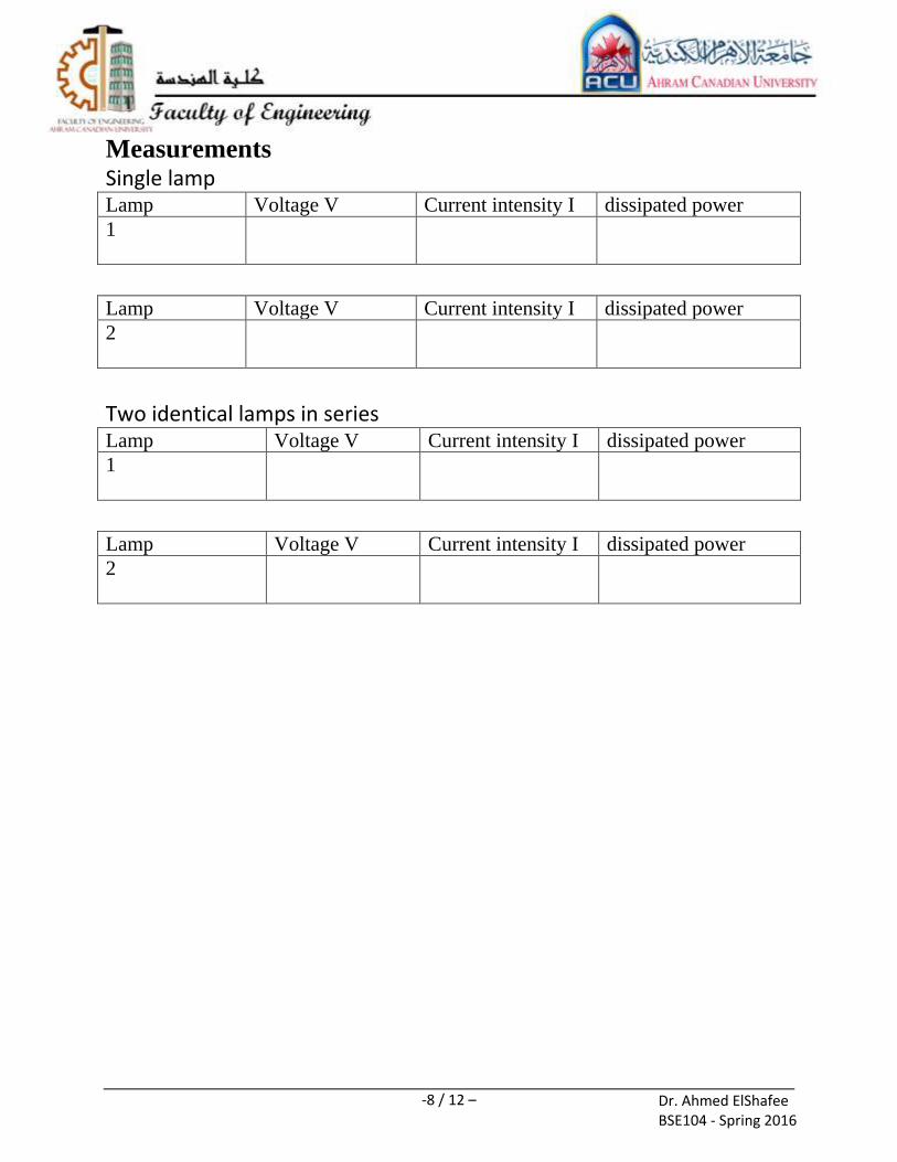
Measurements Single lamp Lamp Voltage V Current intensity I dissipated power
1
Lamp Voltage V Current intensity I dissipated power
2
Two identical lamps in series Lamp Voltage V Current intensity I dissipated power
1
Lamp Voltage V Current intensity I dissipated power
2

-9 / 12 – Dr. Ahmed ElShafee BSE104 - Spring 2016
Experiment (3.3) Parallel connection of incandescent Lamp
Objective Two lamps can be connected to a circuit in two different ways this
experiment deals with parallel connections of incandescent lamps.
To calculate the bulb voltage drop, current and consumed power in case of single bulb connected to power source and in case of two bulbs connected in parallel
Theory In a parallel circuit, each device is directly connected to the power source.
This means that each device receives the same voltage. The amount of current flowing through each device is dependent on the impedance/resistance of that particular device.
If devices are added to the power source in a parallel configuration, the current demand/flow from the power source increases.

-10 / 12 – Dr. Ahmed ElShafee BSE104 - Spring 2016
Procedure
Arrangement of the wiring according to the illustration.
The PIB-lamp holder marked by hatching is not yet inserted.
The ammeter with the measuring range of 100 mA= is used. 6 volts DC is applied.
The switch is closed and the intensity of the lamp is to be noted.
Record measured volt and current
The switch is opened and the PIB-lamp holder marked by hatching is inserted together with the second lamp.
After closing the switch it can be seen that the two lamps burn as intensely as the single lamp used before.

-11 / 12 – Dr. Ahmed ElShafee BSE104 - Spring 2016
Measurements Single lamp Lamp Voltage V Current intensity I dissipated power
1
Two identical lamps in parallel Lamp Voltage V Current intensity I dissipated power
1
Lamp Voltage V Current intensity I dissipated power
2

-12 / 12 – Dr. Ahmed ElShafee BSE104 - Spring 2016
Conclusions Incandescent Lamp considered as non-omic device. Discuss?
……………………………………………….……………………………
………………………………………………….…………………………
………………………………………………….…………………………
………………………………………………….…………………………
………………………………………………….…………………………
………………………………………………….…………………………
………………………………………………….…………………………
Regarding the series/parallel connection of loads, if the source voltage is
constant. Dose it effect the dissipated power by load?
Explain that referring to experiments 3.2, 3.3?
……………………………………………….……………………………
………………………………………………….…………………………
………………………………………………….…………………………
………………………………………………….…………………………
………………………………………………….…………………………
………………………………………………….…………………………
………………………………………………….…………………………
……………………………………………….……………………………
………………………………………………….…………………………
………………………………………………….…………………………
………………………………………………….…………………………
………………………………………………….…………………………
………………………………………………….…………………………
………………………………………………….…………………………
………………………………………………….…………………………
………………………………………………….…………………………
………………………………………………….…………………………