b.s. patel polytechnic, kherva - ganpat...
TRANSCRIPT

PROJECT REPORT
on
B.S. PATEL POLYTECHNIC, KHERVA
Project group : (1) Chaudhary Pravin
(2) Solanki Chirag
(3)VaghelaJaydeep
(4)RabariMehul
(5)Detroja Pratik
Internal guide: H.O.D
Mr. D.M.PATEL Prof.K.P.PATEL
Pedal Power Hacksaw
Page 1

Certificate
This is to certify that Mr.Chaudhary Pravinkumar k. havingEnrolment No
:126440319128 has completed Part-I UDP Project work having title Pedal Power
Hacksaw . He has undergone the process of shodhyatra, literature survey and
problem definition. He is supposed to carry out the residue UDP Part-II work on
same problem during Semester-VI for the final fulfillment of the UDP work which is
prerequisite to complete Diploma Engineering.
Guide – UDP Head of Department
Mr.D.M.PATEL Prof. K.P.PATEL
Page 2

Certificate
This is to certify that Mr. Solanki ChiragkumarR.havingEnrolment No
:126440319134has completed Part-I UDP Project work having title Pedal Power
Hacksaw . He has undergone the process of shodhyatra, literature survey and
problem definition. He is supposed to carry out the residue UDP Part-II work on
same problem during Semester-VI for the final fulfillment of the UDP work which is
prerequisite to complete Diploma Engineering.
Guide – UDP Head of Department
Mr.D.M.PATEL Prof. K.P.PATEL
Page 3

Certificate
This is to certify that Mr. VaghelaJaydeepkumarS.having Enrolment No
:126440319139has completed Part-I UDP Project work having title Pedal Power
Hacksaw . He has undergone the process of shodhyatra, literature survey and
problem definition. He is supposed to carry out the residue UDP Part-II work on
same problem during Semester-VI for the final fulfillment of the UDP work which is
prerequisite to complete Diploma Engineering.
Guide – UDP Head of Department
Mr.D.M.PATEL Prof. K.P.PATEL
Page 4

Certificate
This is to certify that Mr. RabariMehulkumar B.having Enrolment No :
126440319149has completed Part-I UDP Project work .Having title Pedal Power
Hacksaw . He has undergone the process of shodhyatra, literature survey and
problem definition. He is supposed to carry out the residue UDP Part-II work on
same problem during Semester-VI for the final fulfillment of the UDP work which is
prerequisite to complete Diploma Engineering.
Guide – UDP Head of Department
Mr.D.M.PATEL Prof. K.P.PATEL
Page 5

Certificate
This is to certify that Mr. DetrojaPratikkumar A.havingEnrolment No
:126440319145has completed Part-I UDP Project work having title Pedal Power
Hacksaw . He has undergone the process of shodhyatra, literature survey and
problem definition. He is supposed to carry out the residue UDP Part-II work on
same problem during Semester-VI for the final fulfillment of the UDP work which is
prerequisite to complete Diploma Engineering.
Guide – UDP Head of Department
Mr.D.M.PATEL Prof. K.P.PATEL
Page 6

STUDENT PARTICULARS-1
FIRST NAME Pravin
LAST NAME Chaudhary
MOBILE NO. +91 8485979610
EMAIL [email protected]
COLLEGE NAME
B.S.PATEL POLYTECNIC, GANPAT UNIVERSITY.
ADDRESS
BRANCH MECHANICAL ENGINEERING
SEMESTER 5th SEM. YEAR 2014-2015
TEAM NAME
SIGNATURE OF STUDENT
Page 7

STUDENT PARTICULARS-2
FIRST NAME Chirag
LAST NAME Solanki
MOBILE NO. +91 9558275736
EMAIL [email protected]
COLLEGE NAME B.S.PATEL POLYTECNIC, GANPAT UNIVERSITY.
ADDRESS
BRANCH MECHANICAL ENGINEERING
SEMESTER 5th SEM. YEAR 2014-2015
TEAM NAME
SIGNATURE OF STUDENT
Page 8

STUDENT PARTICULARS-3
FIRST NAME Jaydeep
LAST NAME Vaghela
MOBILE NO. +91 9974996488
EMAIL [email protected]
COLLEGE NAME B.S.PATEL POLYTECNIC, GANPAT UNIVERSITY.
ADDRESS
BRANCH MECHANICAL ENGINEERING
SEMESTER 5th SEM. YEAR 2014-2015
TEAM NAME
SIGNATURE OF STUDENT
Page 9

STUDENT PARTICULARS-4
FIRST NAME Mehul
LAST NAME Rabari
MOBILE NO. +91 9974580761
COLLEGE NAME B.S.PATEL POLYTECNIC, GANPAT UNIVERSITY.
ADDRESS
BRANCH MECHANICAL ENGINEERING
SEMESTER 5th SEM. YEAR 2014-2015
TEAM NAME
SIGNATURE OF STUDENT
Page 10

STUDENT PARTICULARS-5
FIRST NAME Pratik
LAST NAME Detroja
MOBILE NO. +91 8734079607
COLLEGE NAME B.S.PATEL POLYTECNIC, GANPAT UNIVERSITY.
ADDRESS
BRANCH MECHANICAL ENGINEERING
SEMESTER 5th SEM. YEAR 2014-2015
TEAM NAME
SIGNATURE OF STUDENT
Page 11

ABSTRACT In this Pedal operated hacksaw machine which can be used for industrial applications and Household needs in which no specific input energy or power is needed. This project consists of a crank and slider mechanism. In the mechanism pedal is directly connected to the hacksaw through crank and slider mechanism for the processing of cutting the wooden blocks, metal bars, pvc materials. The objective of the modal is using the conventional mechanical process which plays a vital role. The main aim is to reduce the human effort for machining various materials such as wooden blocks, steel, PVC etc.
The power hacksaw machine, which runs on human power, works on the principle of the conversion of rotational motion to oscillatory motion.
Importance of this project lies in the very fact that it is green project and helps us to reduce our electricity need. Secondly, this cutter can be used and transferred to our working place easily. Moreover, if we want we can generate electricity with our project by connecting it to dynamo, diode and battery.
Page 12
INDEX
SR.
NO
TOPICS NAME PAGE NO.
1. Introduction Of Project 17
2. Component required 18
3. Working principle 30
4. Designing Aspects and Parts Details/Drawings 31
5. Advantages and Disadvantages 35
6. Cost estimation 36
7. Future Modifications 37
8. Conclusions 40
9. References 41
Page 13

CONTENT
NAME OF CONTENTPAGE NO
TITLE 1 CERTIFICATE 2 STUDENT PARTICULARS 7
ABSTRACT 12 LIST OF TABLE 14
LIST OF FIGURE 16 CHAPTER 1 INTRODUCION 17 CHAPTER 2 COMPONENTS REQUIRD 18
2.1) Pedal power hacksaw 18
2.1.1)Selecting A Power Hacksaw blade 20
2.1.2) Mounting a Power Hacksaw blade 22
2.1.3) Selecting a Band Saw Blade 22
2.1.4) Installing a Band Saw Blade 23
2.2) Pedal arrangement 24
2.2.1) Pedal 24
2.3) Stand Setup Parts 25
2.4) Crank And Slider Mechanism 27
2.5) Metal Slab 28
2.6) Bicycle Seat 29
CHAPTER 3
WORKING PRINCIPLE 30
CHAPTER 4
DESIGN 31
4.1 Base Frame 31
4.2 Upright Support 32
4.3 Hacksaw blade 33
4.4 Design Consideration 33
Page 14

CHAPTER 5
ADVANTAGES 35
DIS ADVANTAGES
CHAPTER 6 COST ESTIMATION 36
CHAPTER 7
FUTURE SCOPE
CHAPTER 8
37
CONCLUSION
CHAPTER 9
40
REFERANCES 41
Page 15

LIST OF FIGURE
SR NO
FIGURE NAME PAGE NO
1 Pedal power Hacksaw cutting system 19
2 Power Hacksaw blade 21
3 Power Hacksaw blade cutting operation 23
4 Pedal 24
5 Pedal power attachment 25
6 Bicycle Stand/Carrier 26
7 crank and slider mechanism 27
8 Metal slab 28
9 Metal slab 28
10 Bicycle sea 29
11 Working 30
12 Base Assembly 31
13 Upright Support Assembly 32
14 Hacks blade 33
15 Rice Threshing 37
16 Winnowing 37
17 Corn Shelling 37
18 Peanut Shelling 38
19 Operating a Circular Saw 38
20 Water Pumping from a Shallow Well 38
21 Operating a Wood Working Lathe
39
Page 16
CHAPTER 1
INTRODUCTION
Pedal power is the transfer of energy from a human source through the use of a foot pedal and
crank system. This technology is most commonly used for transportation and has been used to
propel bicycles for over a hundred years. Less commonly pedal power is used to power
agricultural and hand tools and even to generate electricity. Some applications include pedal
powered laptops, pedal powered grinders and pedal powered water wells. Some third world
development projects currently transform used bicycles into pedal powered tools for sustainable
development. This project concentrates on pedal powered hacksaw machining.
An individual can generate four times more power (1/4 HP) by pedaling than by hand-cranking. At
the rate of ¼ HP, continuous pedaling can be served for only short periods, approximately 10
minutes. However, pedaling at half this power (1/8 HP) can be sustained for close to 60 minutes
but power capability can depend upon age . As a consequence of the brainstorming exercise, it was
apparent that the primary function of pedal power one specific product was particularly useful: the
bicycle. Many devices can be run right away with mechanical energy.
A saw is a tool that uses a hard blade or wire with an abrasive edge to cut through softer materials.
The cutting edge of a saw is either a serrated blade or an abrasive. A saw may be worked by hand,
or powered by steam, water, electric or other power. An abrasive saw uses an abrasive disc or
band for cutting, rather than a serrated blade.
Page 17

CHAPTER 2
COMPONENTS REQUIRED
I. Hack saw blade
II. Pedal arrangement
III. Stand setup parts
IV. Crank and slider mechanism
V. Hack saw assembly
VI. Metal slab
2.1) PEDAL POWER HACKSAW
The principle of pedal power hacksaw is to change circulatory motion or cycling motion into
translatory motion with the help of metal cutting rod. This is mainly used for cutting metals and
plastics. it is manually pedal operated system.
If we use dynamo then we can produce electricity which will be help to lighting the work piece
area when electricity is not available in mechanical workshop.
A hacksaw is a fine-tooth saw with a blade under tension in a frame, used for cutting materials
such as metal or plastics.
Hand-held hacksaw consist of a metal arch with a handle, usually a pistol grip, with pins for
attaching a narrow disposable blade.
A screw or other mechanism is used to used to put the thin blade under tension.
It is a fine tooth hand saw with a blade under tension. It is used to cut metals and PVC pipes. It
would be useful in many projects discussed on this site which used plastic pipes as materials.
Blades of hacksaw are measured in TPI (Tooth Per Inch). Different TPI is needed for different
jobs of cutting.
Page 18
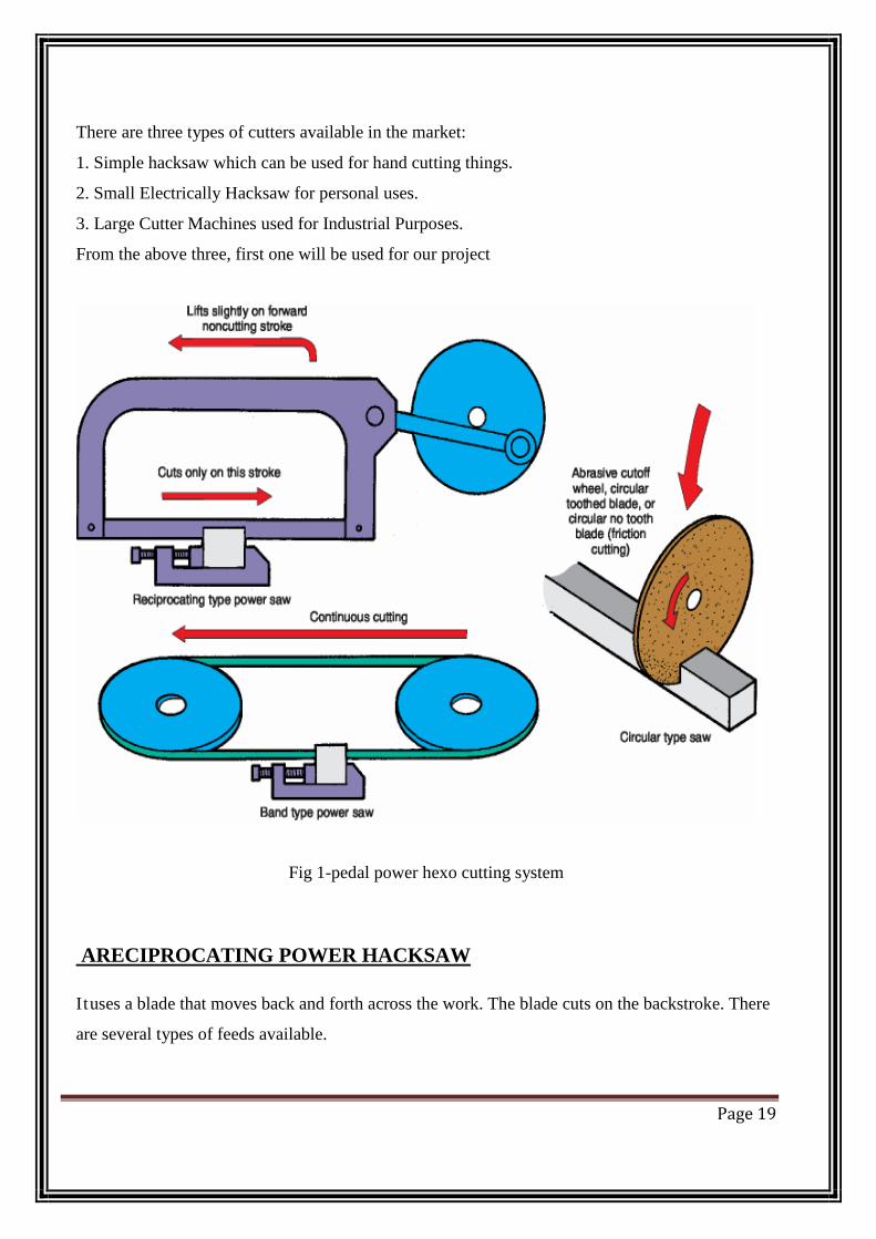
There are three types of cutters available in the market:
1. Simple hacksaw which can be used for hand cutting things.
2. Small Electrically Hacksaw for personal uses.
3. Large Cutter Machines used for Industrial Purposes.
From the above three, first one will be used for our project
Fig 1-pedal power hexo cutting system
ARECIPROCATING POWER HACKSAW
Ituses a blade that moves back and forth across the work. The blade cuts on the backstroke. There
are several types of feeds available.
Page 19
Positive feed-produces an exact depth of cut on each stroke. The pressure on the blade varies with
the number of teeth in contact with the work.
Definite pressure feed-yields a pressure on the blade that is uniform regardless of the number of
teeth in contact with the work. The depth of the cut varies with the number of teeth contacting the
work. This condition prevails with gravity feed.
Feed can be adjusted to meet varying conditions. For best performance, the blade and feed must
be selected to permit high-speed cutting and heavy feed pressure with minimum blade bending
and breakage.
Standard reciprocating metal cutting saws are available in sizes from 6~ ~ 6~ (150 mm ~ 150
mm) to 24~ ~ 24~ (900 mm ~ 900 mm). The saws can be fitted with many accessories, including
quick-acting vises, power stock feed, power clamping of work, and automatic cycling of the
cutting operation. The latter moves the work out the required distance, clamps it, and makes the
cut automatically. The cycle is repeated upon completion of the cut.
High-speed cutting requires use of a coolant. Coolant reduces friction, increases blade life, and
prevents chip-clogged teeth. Cast iron and some brass alloys, unlike most materials, do not
require coolant.
2.1.1) Selecting A Power Hacksaw blade
Proper blade selection is important. Use the three-tooth ruleatleast three teeth must be in con-tact
with the work. Large sections and soft materialsrequire a coarse-tooth blade. Small or thin work and
hard materials require a fine-tooth blade.
For best cutting action, apply heavy feed pressure on hard materials and large work. Use light
feed pressure on soft materials and work with small cross sections.
Blades are made in two principal types: flexible-back and all-hard. The choice depends upon use.
i) Flexible-back blades -should be used where safety requirements demand a shatterproof blade.
These blades should also be used for cutting odd-shaped work if there is a possibility of the work
coming loose in the vise.
ii) All-hard blade -For a majority of cutting jobs, theall-hard bladeis best for straight, accurate
cutting under a variety of conditions.
Page 20
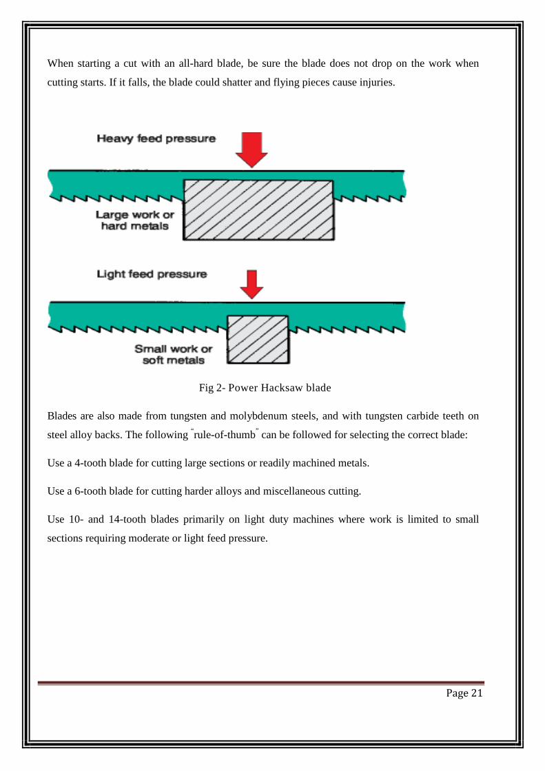
When starting a cut with an all-hard blade, be sure the blade does not drop on the work when
cutting starts. If it falls, the blade could shatter and flying pieces cause injuries.
Fig 2- Power Hacksaw blade
Blades are also made from tungsten and molybdenum steels, and with tungsten carbide teeth on
steel alloy backs. The following “rule-of-thumb” can be followed for selecting the correct blade:
Use a 4-tooth blade for cutting large sections or readily machined metals.
Use a 6-tooth blade for cutting harder alloys and miscellaneous cutting.
Use 10- and 14-tooth blades primarily on light duty machines where work is limited to small
sections requiring moderate or light feed pressure.
Page 21

2.1.2) Mounting a Power Hacksaw blade
The blade must be mounted to cut on the power (back) stroke. The blade must also lie perfectly
flat against the mounting plates. If long lifeand accurate cuts are to be achieved, the blade must be
properly tensioned
Many techniques have been developed for properly mounting and tensioning blades. Use a torque
wrench and consult the manufacturer’s literature. If the information (proper torque for a given
blade on a given machine) is not available, the following methods can be used:
Tighten the blade until a low musical ring is heard when the blade is tapped lightly. A high-
pitched tone indicates that the blade is too tight. A dull thud means the blade is too loose.
The shape of the blade pin hole can serve as an indicator of whether the blade is tensioned
properly. When proper tension is achieved, the pin holes will become slightly elongated,
The blade will become more firmly seated afterthe first few cuts and will stretch slightly. The blade
will require retensioning(retightening) before further cutting can be done.
2.1.3) Selecting a Band Saw Blade
Band saw blades are made with raker teeth or wavy teeth. Most manufacturers also make
variations of these sets. The rakerset is preferred for general use.
Tooth pattern determines the efficiency of a blade in various materials. The s tandard tooth
blade pattern is best suited for cutting most ferrous metals. A skip tooth blade pattern is
preferred for cutting aluminum, magnesium, copper, and soft brasses. The hooktooth blade
pattern also is recommended for most nonferrous metallic materials.
For best results, consult the blade manufacturer’s chart or manual for the proper blade
characteristics (set, pattern, and number of teeth per inch) for the particular material being cut.
Page 22
2.1.4) Installing a Band Saw Blade
If the saw is to work at top efficiency, the blade must be installed carefully. Wear heavy leather
gloves to protect your hands when installing a band saw blade.
Blade guides should be adjusted to provide adequate support, Proper blade support is required to
cut true and square with the holding device.
Follow the manufacturer’s instructions for adjusting blade tension. Improper blade tension ruins
blades and can cause premature failure of bearings in the drive and idler wheels.
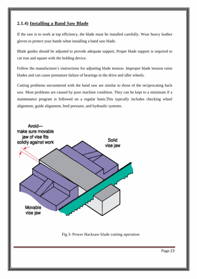
Cutting problems encountered with the band saw are similar to those of the reciprocating hack
saw. Most problems are caused by poor machine condition. They can be kept to a minimum if a
maintenance program is followed on a regular basis.This typically includes checking wheel
alignment, guide alignment, feed pressure, and hydraulic systems.
Fig 3- Power Hacksaw blade cutting operation
Page 23

2.2) PEDAL ARRANGEMENT
A pair of pedals is attached to the stand setup in which the power will be generated manually. A
typical Bicycle arrangement is used.
2.2.1) PEDAL
A bicycle pedal is the part of a bicycle that the rider pushes with their foot to propel the bicycle. It
provides the connection between the cyclist’s foot or shoe and the crank allowing the leg to turn
the bottom bracket spindle and propel the bicycle's wheels.
Fig 4- pedal
Pedals were initially attached to cranks connecting directly to the driven (usually front) wheel.
The safety bicycle, as it is known today, came into being when the pedals were attached to a crank
driving a sprocket that transmitted power to the driven wheel by means of a roller chain.
Pedals usually consist of a spindle that threads into the end of the crank and a body, on which the
foot rests or is attached, that is free to rotate on bearings with respect to the spindle.
Page 24

Fig 5- pedal power attachment
2.3) STAND SETUP PARTS
Stands are introduced to immobilize the apparatus. Various components used are fixed to this
arrangement. The chassis of the bicycle is used as the stand setup parts .
The stand described here is designed to support most bicycles.
Page 25

Fig 6- Bicycle Stand/Carrier
1. The stand assembly is divided into two parts: the rectangular base frame and two triangular
upright supports. Measure and cut the five pieces of 3/4" (20mm) angle specified for the base
frame. Mitre the corners at 45 degrees so they fit together tightly and form square corners.
2. Weld the rectangle together. Do not weld the center frame member to the rectangle yet.
3. Measure and cut as specified the 5 pieces for each upright support.
4. Carefully assemble the upright support pieces for welding, being sure to leave a 1/8"
(3.2mm) gap in the base of each support. This gap will mate with the center frame member of the
base frame, allowing the upright supports to slide to accommodate different rear axle widths. Note
that the two upright supports are not identical. They are mirror reflections of one another. Weld
each upright support assembly together into a secure structure.
5. Place the upright supports onto the base frame, and position the center frame member so that
it mates with the gap in the side supports. Mark its position, and weld it in place.
Page 26
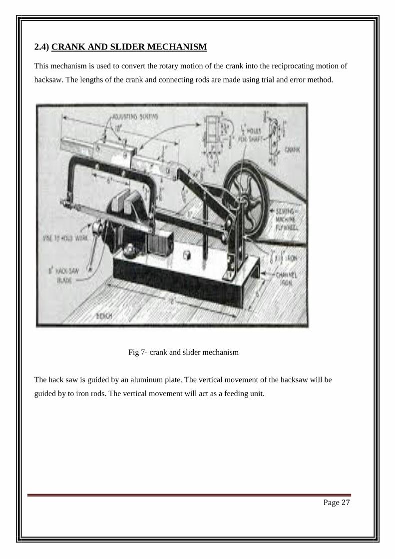
2.4) CRANK AND SLIDER MECHANISM
This mechanism is used to convert the rotary motion of the crank into the reciprocating motion of
hacksaw. The lengths of the crank and connecting rods are made using trial and error method.
Fig 7- crank and slider mechanism
The hack saw is guided by an aluminum plate. The vertical movement of the hacksaw will be
guided by to iron rods. The vertical movement will act as a feeding unit.
Page 27
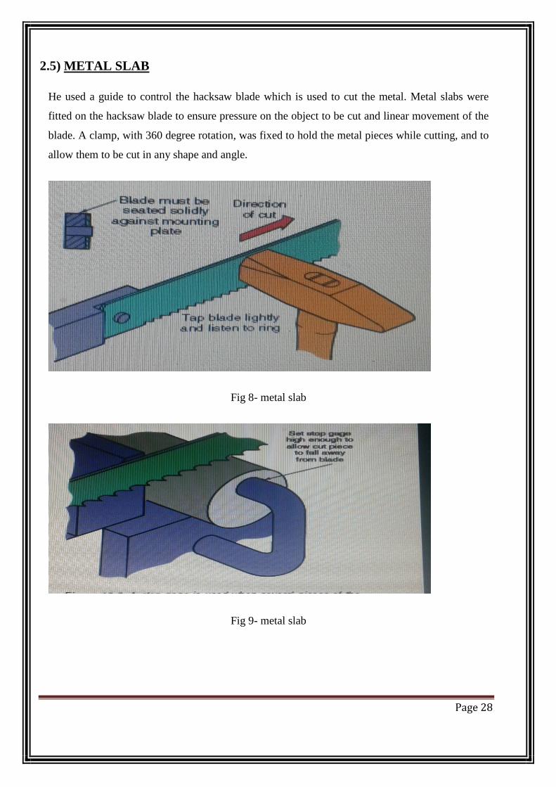
2.5) METAL SLAB
He used a guide to control the hacksaw blade which is used to cut the metal. Metal slabs were
fitted on the hacksaw blade to ensure pressure on the object to be cut and linear movement of the
blade. A clamp, with 360 degree rotation, was fixed to hold the metal pieces while cutting, and to
allow them to be cut in any shape and angle.
Fig 8- metal slab
Fig 9- metal slab
Page 28

2.6) BICYCLE SEAT
Fig 10- bicycle seat
A bicycle seat, unlike a bicycle saddle, is designed to support the rider's buttocks and back, usually
in a semi-reclined position. Arthur Graford is credited with inventing the padded bicycle seat in
1892, and they are now usually found on recumbent bicycles.
Bicycle seats come in three main styles; mesh, hard shell and combination
i) MESH
A typical mesh seat consists of a metal frame with mesh stretched over it and secured with
adjustable straps, zip ties, string or shock cord.
ii)HARDSHELL
Hard shell seats are normally made of a composite material such as GRP or carbon fiber although
metal and wood versions do exist. A hard-shell seat is normally covered with some-form of
padding, this is usually closed or open cell foam although some extreme racing machines do not
have any padding on the seat to reduce weight and increase efficiency. Hard-shell seats are
generally used at more reclined angles than mesh seats.
iii)COMBINATION
A combination seat has a padded hard seat base with a mesh back.
Page 29
CHAPTER 3
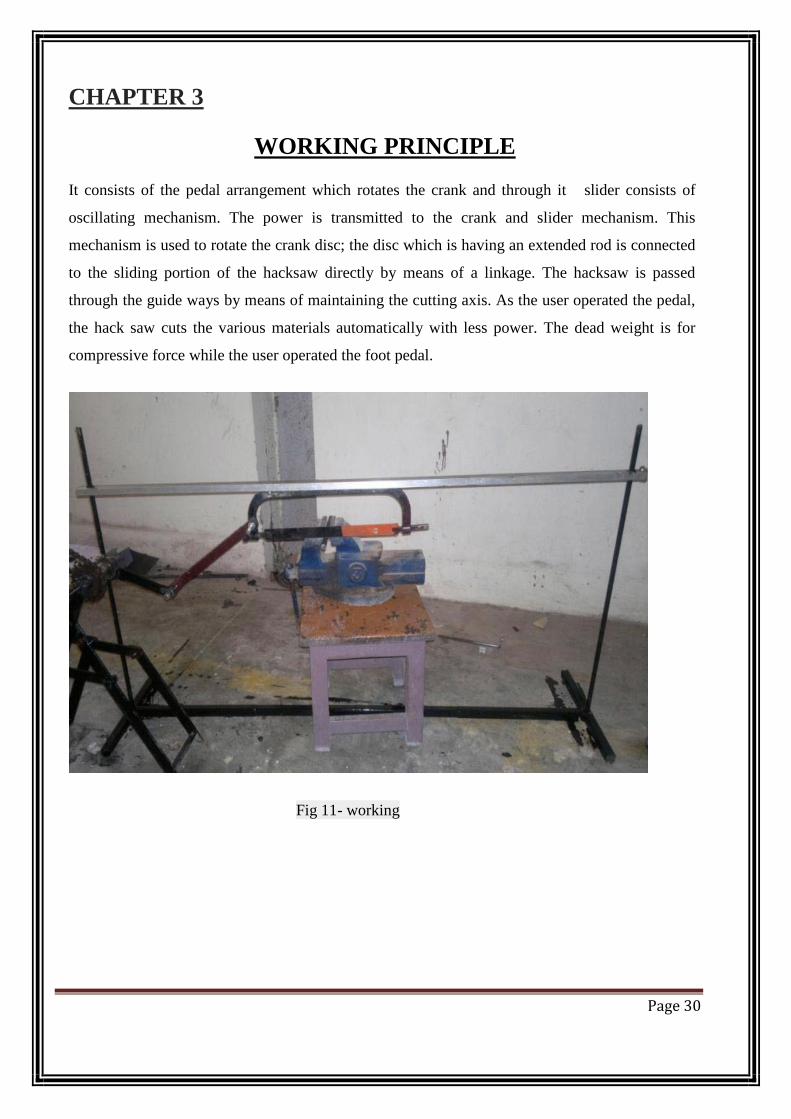
WORKING PRINCIPLE It consists of the pedal arrangement which rotates the crank and through it slider consists of
oscillating mechanism. The power is transmitted to the crank and slider mechanism. This
mechanism is used to rotate the crank disc; the disc which is having an extended rod is connected
to the sliding portion of the hacksaw directly by means of a linkage. The hacksaw is passed
through the guide ways by means of maintaining the cutting axis. As the user operated the pedal,
the hack saw cuts the various materials automatically with less power. The dead weight is for
compressive force while the user operated the foot pedal.
Fig 11- working
Page 30

CHAPTER 4
DESIGN
4.1) BASE FRAME
Plan view of frame in support position. All pieces 3/4" (19mm) steel angle.
Fig 12-Base Assembly
Page 31

4.2)UPRIGHT SUPPORTS
Make two pieces of upright supports: one as shown and another one a reflection of the one
shown below. All pieces are made of 3/4" (19mm) steel angle, unless specified otherwise. Weld
all joints.
Fig 13-Upright Support Assembly
Page 32
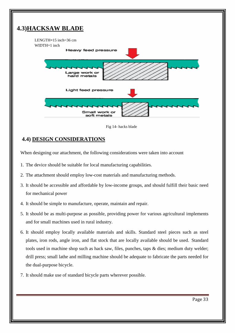
4.3)HACKSAW BLADE
LENGTH=15 inch=36 cm WIDTH=1 inch
Fig 14- hacks blade
4.4) DESIGN CONSIDERATIONS
When designing our attachment, the following considerations were taken into account
1. The device should be suitable for local manufacturing capabilities.
2. The attachment should employ low-cost materials and manufacturing methods.
3. It should be accessible and affordable by low-income groups, and should fulfill their basic need
for mechanical power
4. It should be simple to manufacture, operate, maintain and repair.
5. It should be as multi-purpose as possible, providing power for various agricultural implements
and for small machines used in rural industry.
6. It should employ locally available materials and skills. Standard steel pieces such as steel
plates, iron rods, angle iron, and flat stock that are locally available should be used. Standard
tools used in machine shop such as hack saw, files, punches, taps & dies; medium duty welder;
drill press; small lathe and milling machine should be adequate to fabricate the parts needed for
the dual-purpose bicycle.
7. It should make use of standard bicycle parts wherever possible.
Page 33

8. The device should adapt easily to as many different bicycles as possible. No permanent
structural modification should be made to the bicycle.
9. Though the device should be easy to take off the bicycle, it is assumed that it would usually
remain attached to facilitate readiness and ease of transport from site to site. The device,
therefore, should not interfere with the bicycle's transportation mode.
10. The broad stand, which provides stability during power production mode, can be flipped
upward during the transport mode. This stand/carrier would be a permanent fixture of the dual-
purpose bicycle.
11. The power take-off mechanism should be as efficient as possible, and should develop
relatively high r.p.m. (close to 200) for versatility of application. We had seen designs for
devices that take power from the rear tire by means of a friction roller pressed against it, but we
had doubts about the efficiency of this arrangement. In order to improve efficiency we used
hard bearing surfaces such as roller chains, sprockets and ball bearings. We decided that the
most appropriate location for this power take-off mechanism would be at the front of the bike
near the fork tube (see photographs).
12. Care must be exercised to insure that the power take-off assembly is far enough forward so as
not to interfere with pedaling. Most standard adult bicycle frames have plenty of room for the
power take-off mechanism and pulley. Power is supplied to the shaft by means of a chain from
the bike's chain wheel (crank) to a ratcheted sprocket on the shaft. During the prime-mover
mode, the bike's regular chain is slipped off of the chain-wheel, and the specially sized chain to
the power take-off mechanism is slipped on.
13. The device should be able to transmit power to a variety of machines, and changing drive
ratios should be as simple as possible. We decided that a V-belt and pulley arrangement would
be most appropriate for this. Belts do not require the precise alignment that chains do. Belts can
even accommodate pulleys that are slightly skewed with respect to each other. Changing drive
ratios is as easy as changing pulleys. Also, belts are reasonably efficient.
14. The device should contain a ratcheting mechanism that would let the operator "coast "
periodically to rest and conserve energy. A free wheel from any bicycle can be easily adapted
for this purpose.
15. Excessive weight should be avoided, as durability is a prime consideration.
Page 34

CHAPTER 5
ADVANTAGES
I. Time saving as compared to simple hacksaw
II. Power saving as it is manually operated
III. Easy machinery used
IV. As it is pedal operated so good for health
V. Comfortable then ordinary hacksaw
VI. It is portable
VII. It could be used wherever metal cutting is done in small scales, including at construction
sites and furniture units, or to cut metal for window panes.
DISADVANTAGES
I. Its totally manually operated
II. Time consuming as compared to electrical power hacksaw
III. Without human effort its not operated
IV. Not fit for heavy production
Page 35

CHAPTER-6
Cost Estimation
SR.NO. NAME OF
COMPONENT
PIECES PRICE/PIECE TOTAL
1 Pedal 2 200 400
2 Stand 1 350 350
3 Base frame 1 750 750
4 Crank& Slider
mechanism
1 900 900
5 Clamp 2 130 260
6 Hacksaw 1 550 550
7 Nut & Bolt 7 10 70
8 Welding cost - 380 380
TOTAL 3660
Page 36
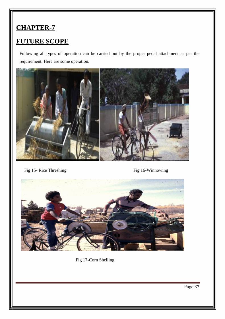
CHAPTER-7
FUTURE SCOPE
Following all types of operation can be carried out by the proper pedal attachment as per the
requirement. Here are some operation.
Fig 15- Rice Threshing Fig 16-Winnowing
Fig 17-Corn Shelling
Page 37
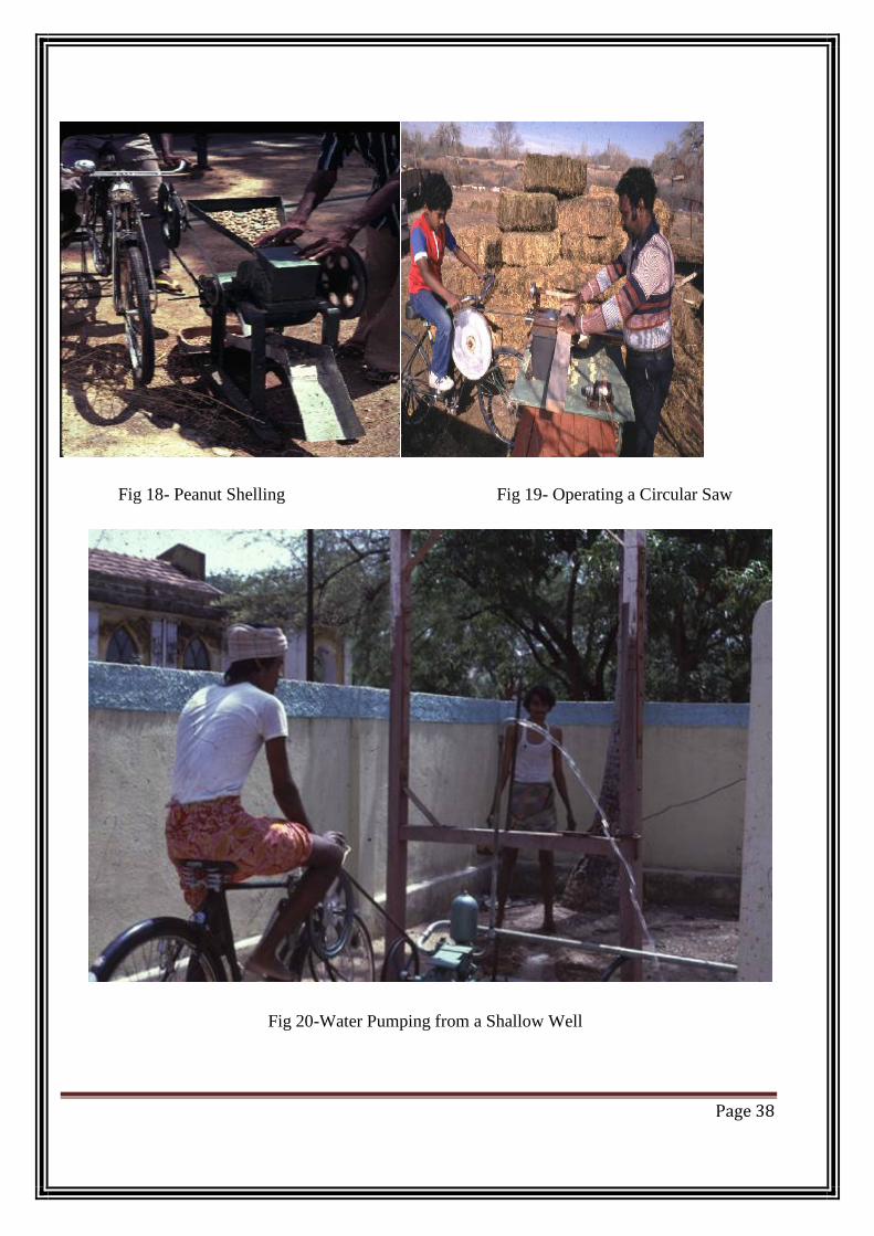
Fig 18- Peanut Shelling Fig 19- Operating a Circular Saw
Fig 20-Water Pumping from a Shallow Well
Page 38
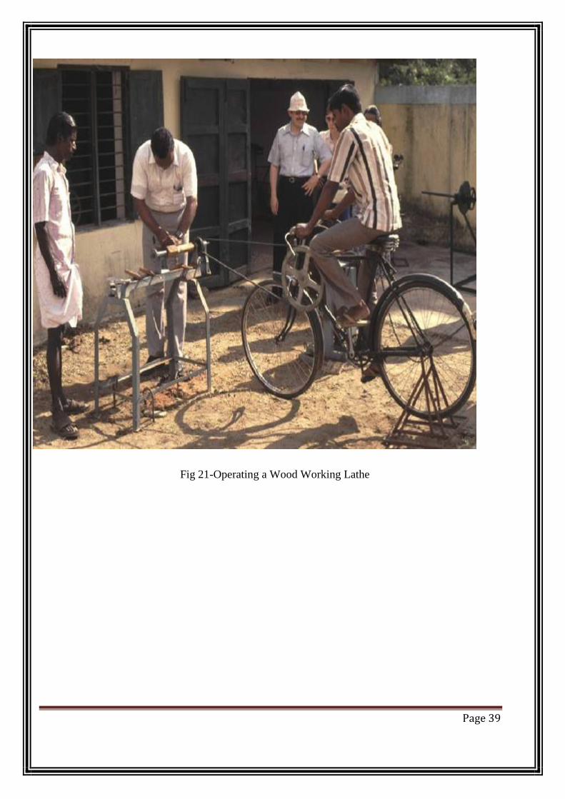
Fig 21-Operating a Wood Working Lathe
Page 39

CHAPTER-8
CONCLUSION Thus a low cost and simple design pedal operated hacksaw machine is fabricated. This machine
reduces the human effort and hence we don’t need two persons to cut the wooden logs. This
simple design of conventional design which can enhance day today household needs and daily
day to day purposes and it can be also used in for industrial applications during power shut down
scenarios. By using this method we can do any operation as per our requirement without the use
of electricity. so we can save the electrical power.
Page 40
CHAPTER-9
REFERENCES [1] David Gordon Wilson “UNDERSTANDING PEDAL POWER” ISBN: 0-86619-268-9 [C]
1986, Volunteers in Technical Assistance” Technical paper 51 VITA 1600 Wilson Boulevard
USA.
[2] EJ Yerxa Taylor & Francis “Occupational science: A new source of power for participants in
occupational therapy‟- Journal of Occupational Science ISSN 1442-7591 Volume: 13, Issue: 1,
April 1993 pp254-259.
[3] Jon Leary “Putting Research into Practice: From a Steel City Drawing Board to the Heart of
the Maya” The University of Sheffield-EWB-UK National Research Conference 2010,19th
February 2010.
Page 41