bs 5493
TRANSCRIPT

Lice
nsed
Cop
y: P
uan
Ms.
Nor
haya
ti, P
etro
liam
Nas
iona
l Ber
had,
05
Aug
ust 2
002,
Unc
ontr
olle
d C
opy,
(c)
BS
I

BRITISH STANDARD BS 5493:1977Incorporated by Amendment No. 2
Code of practice for
Protective coating of iron and steel structures against corrosion
(Formerly CP 2008)
UDC 624.014.2:691.71:620.197.6
Lice
nsed
Cop
y: P
uan
Ms.
Nor
haya
ti, P
etro
liam
Nas
iona
l Ber
had,
05
Aug
ust 2
002,
Unc
ontr
olle
d C
opy,
(c)
BS
I

BS 5493:1977
This British Standard, having been prepared under the direction of the Codes of Practice Committee for Civil Engineering was published under the authority of the Executive Board on 31 October 1977.
© BSI 11-1998
First published, as CP 2008, October 1966First revision October 1977
The following BSI references relate to the work on this standard:Committee reference BDB/7Draft for comment 75/12246 DC
ISBN 0 580 09565 7
Code Drafting Committee Prevention of corrosion
Chairman Mr K A Chandler Engineering Equipment Users Association
Mr L S Evans
Association of Metal Sprayers Mr J C Bailey Institute of British Foundrymen Dr R V RileyMr E J Cunningham Institute of Metal Finishing Dr M ClarkeMr E A Gerhold Institution of Civil Engineers Mr W F LeemingMr R E Mansford Institution of Corrosion
TechnologyMr D A Bayliss
British Cast Iron Research Association
Mr D R Whitchurch Institution of Electrical Engineers
Mr H Gosden
British Constructional Steelwork Association
Mr F I Lees Institution of Gas Engineers Dr J T HarrisonMr F H Needham Institution of Municipal
EngineersMr K C Horton
British Gas Corporation Dr J T Harrison Mr T IrvingBritish Iron and Steel Research
AssociationMr K A Chandler Institution of Structural
EngineersMr A G Senior
British Railways Board Mr D F Goodman Institution of Water Engineers & Scientists
Mr K J Reynolds
Mr F D Timmins Ministry of Defence Mr D A ChapmanBritish Steel Corporation Mr A K Allan Mr J Garland
Mr G A Orton Mr G ScholesCo-opted Mr C A Pequignot National Coal Board Dr I Evans
Mr D Pye National Federation of Painting and Decorating Contractors
Mr S J Benge-Abbott
Mr A G WalkerConstruction Industry Research
and Information AssociationMr P Pullar-Strecker Paint Research Association Mr A W Bullett
Paintmakers Association of Great Britain Ltd.
Mr A E Claxton
Council of Ironfoundry Association
Mr D R Whitchurch Mr A T S Rudram
Department of the Environment —
Mr P Whiteley Royal Institute of British Architects
Mr D A S Goodman
Building Research Establishment,
Royal Institution of Chartered Surveyors
Mr F J Cave
Building Research Station White Lead Manufacturers Association
Mr M R Pettitt
Department of the Environment (PSA)
Mr R H Cutts Zinc Development Association Mr F C Porter
Department of the Environment (Highways)
Mr P Elliott Chairman of ISE/28 Mr N S Making
Mr T A RochesterDepartment of the
Environment — Dr R R Bishop
Transport and Road Research Laboratory
Electricity Supply in England and Wales
Mr I P Gillson
Mr A Meredith
Amendments issued since publication
Amd. No. Date of issue Comments
4443 January 1984
7898 November 1993
Indicated by a sideline in the margin
Lice
nsed
Cop
y: P
uan
Ms.
Nor
haya
ti, P
etro
liam
Nas
iona
l Ber
had,
05
Aug
ust 2
002,
Unc
ontr
olle
d C
opy,
(c)
BS
I
BS 5493:1977
© BSI 11-1998 i
Contents
PageCode drafting committee Inside front coverForeword viii
Section 1. General1 Scope 12 References 13 Use of the code 13.1 General 13.2 Use by the experienced specifier 13.3 Use by the non-technical specifier 13.4 Specification requirements 2
Section 2. Factors influencing the choice of protective systems4 General 34.1 Recognition of the problem 34.2 Questions related to design, use and site requirements 34.3 Questions relating to coating systems 45 Environment 55.1 Classification of types 55.2 Identification of relevant types 56 Life required of coating 56.1 Definition 56.2 Categories 56.2.1 Life to first maintenance 56.2.2 Life between subsequent maintenances 56.3 Assessment of life requirement 67 Design of the structure 68 Fabrication 88.1 General 88.2 Faying surfaces of friction-grip joints 88.3 Fasteners 88.4 Procedure for welds 89 Facilities for application of coatings 910 Classification and characteristics of protective coatings 910.1 Classification 910.2 Characteristic advantages of metal and paint coatings 4110.3 Other coatings 4110.4 Application facilities 4110.5 Effects of delays during application 4210.6 Costs 4211 Characteristics of metallic coatings 4211.1 Zinc coatings (other than zinc-rich paints) 4211.1.1 General 4211.1.2 Galvanizing 4211.1.3 Sherardizing 4311.1.4 Electroplating 4311.2 Sprayed-metal coatings 4311.2.1 General 4311.2.2 Sprayed-metal-plus-sealer systems 4311.3 Metal-plus-paint systems 43
Lice
nsed
Cop
y: P
uan
Ms.
Nor
haya
ti, P
etro
liam
Nas
iona
l Ber
had,
05
Aug
ust 2
002,
Unc
ontr
olle
d C
opy,
(c)
BS
I

BS 5493:1977
ii © BSI 11-1998
Page11.3.1 General 4311.3.2 Zinc coatings plus paint 4312 Characteristics of paint systems (including metallic zinc-rich
paints) 4412.1 General 4412.1.1 Binders 4412.1.2 Pigments 4412.1.3 High-build coatings 4412.1.4 Compatibility 4412.1.5 Solvents 4412.1.6 Handling, stacking and repair 4412.2 Zinc-rich paints 4412.3 Drying-oil-type paints 4512.4 One-pack chemical-resistant paints 4512.5 Two-pack chemical-resistant paints 4512.6 Bituminous coatings 4512.6.1 General 4512.6.2 Coal tar pitches and bitumens 4512.6.3 Asphaltic coatings 4612.6.4 Application of coal tar pitches and asphalts 4612.6.5 Overcoating 4613 Characteristics of some other protective systems 4613.1 Powder coatings 4613.2 Grease paints 4613.3 Wrapping tapes and sleeves 4613.3.1 Petroleum-jelly tapes 4713.3.2 Synthetic resin or plastic tapes 4713.3.3 Coal tar and bitumen tapes 4713.3.4 Two-pack taping 4713.3.5 Plastic sleeves 4713.4 Protection of steel by cement and allied products 4713.5 Cathodic protection 4714 Surface preparation 4714.1 General 4714.2 Degreasing 4814.3 Removal of scale and rust 4814.3.1 Blast-cleaning 4814.3.2 Acid-pickling 5214.3.3 Flame-cleaning 5214.3.4 Manual cleaning 5214.4 Attention to detail 53
Section 3. Specifications and technical requirements15 Introduction 5415.1 The scope of this section 5415.2 The need for specifications 5415.3 The prime function of a Specification 5415.4 Responsibilities in preparing a Specification 5415.5 The communicative value of a Specification 55
Lice
nsed
Cop
y: P
uan
Ms.
Nor
haya
ti, P
etro
liam
Nas
iona
l Ber
had,
05
Aug
ust 2
002,
Unc
ontr
olle
d C
opy,
(c)
BS
I

BS 5493:1977
© BSI 11-1998 iii
Page15.6 Schedules 5515.7 Details 5615.8 Definition and allocation of responsibilities 5616 Surface preparation 5616.1 Degreasing 5616.2 Removal of rust and scale 5616.2.1 Blast-cleaning 5616.2.2 Acid-pickling 5716.2.3 Flame-cleaning 5716.2.4 Manual cleaning 5817 Coating system 5818 Stripe coats 5819 Control of thickness of paint coating 5820 Control of thickness of metal coating 5920.1 Galvanizing 5920.2 Sprayed metal 5921 Materials 5921.1 Availability 5921.2 Control of materials 5921.2.1 Storage 5921.2.2 Testing 5921.3 Preparation for use 5922 Application of protective coatings 6022.1 General 6022.2 Painting 6022.2.1 Brush-painting 6022.2.2 Spray-painting 6022.2.3 Other methods 6122.2.4 Surface finish 6122.2.5 Paint application procedure trials 6122.2.6 Other general requirements of a painting Specification 6122.3 Galvanizing and metal-spraying 6122.4 Wrapping 6122.5 Mastics and sealants 6223 Working conditions 6223.1 General 6223.2 Temperature 6223.3 Humidity 6223.4 External conditions 6323.5 Contamination of prepared surfaces and wet film 6523.6 Shop conditions 6523.7 Lighting 6523.8 Hot conditions 6523.9 Health and safety 6524 Handling, transport, storage and erection 6524.1 Selection of coating systems 6524.2 Methods of preventing damage 66
Lice
nsed
Cop
y: P
uan
Ms.
Nor
haya
ti, P
etro
liam
Nas
iona
l Ber
had,
05
Aug
ust 2
002,
Unc
ontr
olle
d C
opy,
(c)
BS
I

BS 5493:1977
iv © BSI 11-1998
Page24.3 Storage of coated steelwork 6624.4 Responsibilities for preventing damage 6625 Treatments for connections and other special areas 6625.1 General requirements 6625.2 Bolts 6725.3 Surfaces of connections joined by bolts 6825.3.1 Non-friction-grip bolted connections 6825.3.2 Faying surfaces of structural connections joined by
high-strength friction-grip bolts 6825.4 Welded work 6825.5 Clearance for coatings 6926 Manhole and joint cover plates, pipe couplings and other
small items 6927 Machined and bearing surfaces 6928 Steel in contact with other materials 6928.1 Coating system 6928.2 Steel embedded in concrete 6928.3 Steel in contact with timber 6928.4 Steel in contact with other metals 6928.5 Steel in contact with or near rain-washed concrete 6928.6 Steel near to surfaces subject to treatment with road
(de-icing) salts 6929 Surfaces inaccessible on completion 6930 Ancillary equipment 7031 Use of desiccants 7032 Remedial work 7032.1 General 7032.2 Defects resulting from unsatisfactory application 7032.3 Defects resulting from inferior preparation, materials or
workmanship 7032.4 Early degradation of coatings 7032.5 Other remedial measures 7033 Specifications for maintenance coatings 7033.1 Factors for consideration 7033.2 Compatibility of maintenance with original system 7133.3 Location of different treatments 7133.4 Coating schedule 7134 Final check 71
Section 4. Inspection35 Introduction 7236 Duties of the Inspector 7237 Levels of inspection 7238 Inspection schedule 7239 Inspection record and reports 7340 Inspection organization 7341 Measurement of film thickness 7341.1 Methods available 7341.2 Procedures 7341.3 Calculations 74
Lice
nsed
Cop
y: P
uan
Ms.
Nor
haya
ti, P
etro
liam
Nas
iona
l Ber
had,
05
Aug
ust 2
002,
Unc
ontr
olle
d C
opy,
(c)
BS
I

BS 5493:1977
© BSI 11-1998 v
Page42 Sampling of materials 7443 Inspection guide 74
Section 5. Maintenance44 The need for maintenance 8745 Basic considerations of maintenance procedure 8746 Factors affecting decisions on maintenance 8746.1 Condition of coatings 8746.2 Variability of deterioration according to location 8846.3 Factors affecting deterioration 8846.3.1 General 8846.3.2 Effects of design on rates of deterioration 8846.3.3 Effects of environment on rates of deterioration 8846.4 Type and use of structure 8847 Factors affecting choice of procedure 8847.1 Environment 8847.2 Constraints on site 8948 Organization 8948.1 Labour 8948.2 Inspection 8948.3 Conduct of work on site 8949 Choice of maintenance method 8950 Choice of procedures 8951 Surface preparation 9051.1 General 9051.2 Factors appropriate to use of different methods on site 9051.2.1 Blast-cleaning with or without the addition of water 9051.2.2 Flame-cleaning 9151.2.3 Powered tools 9151.2.4 Hand-operated tools 9152 Application 9153 Standards of preparation 9154 Standards of application 9154.1 General 9154.2 Brushing 9154.3 Roller-coating 9154.4 Spray application 9255 Recommendations for coatings 9255.1 General 9255.2 Previously painted steelwork 9255.3 Previously metal-coated steelwork with or without additional
coating 92
Section 6. Safety and health56 Legislation 9556.1 Health and Safety at Work etc. Act 1974 9556.2 Factories Act 1961 9556.3 The Control of Pollution Act 1974 9557 Operational hazards 9557.1 General 9557.2 Hazards to structure and surroundings 96
Lice
nsed
Cop
y: P
uan
Ms.
Nor
haya
ti, P
etro
liam
Nas
iona
l Ber
had,
05
Aug
ust 2
002,
Unc
ontr
olle
d C
opy,
(c)
BS
I

BS 5493:1977
vi © BSI 11-1998
Page57.3 Risk of injury 9657.3.1 Eyesight 9657.3.2 Hearing 9657.3.3 Respiratory system 9658 General hygiene 96
Appendix A General principles of corrosion and its control 97Appendix B Characteristics of paint binders 109Appendix C Characteristics of paint pigments 111Appendix D Sampling of paint 113Appendix E Choosing the most economical defence against corrosion 113Appendix F Methods for control of preparation (by blast-cleaning) 115Appendix G Test for detecting soluble rust-producing salts remaining on blast-cleaned steel 116Appendix H Example of use of the code 116Appendix J References and bibliography 121
Index 122
Figure 1 — Typical lives of zinc coatings in selected environments 24Figure 2 — Corrosion points 101Figure 3 — Crevices 102Figure 4 — Air circulation e.g. pipeline support 104Figure 5 — Drainage 104Figure 6 — Protection of a stanchion at ground level 105Figure 7 — Corrosion at gap in surrounding concrete 106Figure 8 — Design for coating 107Figure 9 — Access for maintenance 107Figure 10 — Shop coating costs relative to thickness of steel 114Figure 11 — Assessment of steel cleaning 116
Table 1 — Environments and special situations 6Table 2 — Principal types of coating systems 10Table 3 — Recommendations for protective coating systems for specific environments 11Table 4 — Typical coating systems and their components 25Table 4A — Product section AP. Blast primers 26Table 4B — Group B systems. Zinc coatings other than sprayed 27Table 4C — Part 1: Group C systems. Sprayed-metal coatings 28Table 4D — Part 1: Group D systems. Organic zinc-rich systems 29Table 4E — Part 1: Group E systems. Inorganic zinc-rich systems 30Table 4F — Part 1: Group F systems. Drying-oil-type paints 30Table 4G — Group G systems. Silicone alkyd paint over two-packprimer and undercoat 34Table 4H — Part 1: Group H systems. One-pack chemical-resistant paints 34Table 4J — Group J system. Drying-oil-type primer with one-pack chemical-resistant undercoat and finish 36Table 4K — Part 1: Group K systems. Two-pack chemical-resistantpaint 36Table 4L — Group L systems. Two-pack primer and undercoat overcoated with one-pack chemical-resistant finish [or travel coat (tie coat)] and site finish 39
Lice
nsed
Cop
y: P
uan
Ms.
Nor
haya
ti, P
etro
liam
Nas
iona
l Ber
had,
05
Aug
ust 2
002,
Unc
ontr
olle
d C
opy,
(c)
BS
I

BS 5493:1977
© BSI 11-1998 vii
PageTable 4M — Product section MF. Bitumen and coal tar products 40Table 4N — Notes to tables 4A to 4M 41Table 5 — Methods of blast-cleaning 50Table 6 — Classification of abrasives used for cleaning steel 51Table 7 — Common types of mastics and sealants 64Table 8 — Inspection guide 76Table 9 — Treatment of previously painted steelwork 93Table 10 — Site treatment of previously metal-coated steelwork 94Table 11 — The effect of atmospheric pollution on corrosion 97Table 12 — Comparison of paint performance with the corrosion rate of bare steel 98Table 13 — Suggested layout of a cost-calculation table 115
Standards publications referred to Inside back cover
Lice
nsed
Cop
y: P
uan
Ms.
Nor
haya
ti, P
etro
liam
Nas
iona
l Ber
had,
05
Aug
ust 2
002,
Unc
ontr
olle
d C
opy,
(c)
BS
I

BS 5493:1997
viii © BSI 11-1998
Foreword
This code of practice was originally published, under the number CP 2008, in 1966; in accordance with BSI policy whereby codes of practice are now published in the general series of British Standards, this revision is published as BS 5493. The code was originally drawn up to assist those responsible for the choice or application of measures to protect iron and steel from corrosion.Since that time developments have taken place in both the methods and processes concerned with the protection of steel from corrosion, and this new edition has been prepared to take account of these changes.The total content of the code has been reduced, the format has been revised, and much of the explanatory matter that appeared in the original code has been omitted but essential background information has been included in the appendices. The section on cathodic protection has been omitted entirely and reference should be made to BS 7361-1. Sections on specifications and inspection have been included and this reflects the importance attached to these matters as a means of achieving the full potential of protective coatings in practice.A new feature of this code is the inclusion of reference numbers for complete protective systems and also for their component parts. This should be of particular assistance to users where coatings or materials do not comply with the relevant British Standards. Although some compositional requirements of the coating materials are included, these are not sufficiently detailed to provide more than a general indication of the characteristics of the coatings, and are not intended to be used as standards.The treatments suggested represent the minimum acceptable standard of good practice for important steel structures. In some buildings and structures of less importance lower standards of protection may be acceptable but the reduction of initial costs will generally result in higher maintenance costs. Where steelwork is fully encased, e.g. in concrete, the standard of protection will generally be lower than that recommended here.Protective processes are constantly being developed and improved, the recommendations in the code cannot, therefore, be final and are not intended to discourage the use of other measures and materials where they can be shown to be equivalent to or better than those recommended here.BS 5493 has been amended to accord with current UK health and safety legislation, as a holding exercise pending changes in legislation resulting from EC Directives. References in BS 5493 to other British Standards have also been updated.A British Standard does not purport to include all the necessary provisions of a contract. Users of British Standards are responsible for their correct application.
Compliance with a British Standard does not of itself confer immunity from legal obligations.
Summary of pagesThis document comprises a front cover, an inside front cover, pages i to viii, pages 1 to 130, an inside back cover and a back cover.This standard has been updated (see copyright date) and may have had amendments incorporated. This will be indicated in the amendment table on the inside front cover.
Lice
nsed
Cop
y: P
uan
Ms.
Nor
haya
ti, P
etro
liam
Nas
iona
l Ber
had,
05
Aug
ust 2
002,
Unc
ontr
olle
d C
opy,
(c)
BS
I

BS 5493:1977
© BSI 11-1998 1
Section 1
Section 1. General
1 ScopeThis code classifies recommended methods of protection against corrosion of iron and steel structures exposed to environments commonly encountered. It describes the various methods in detail and gives guidance on how to specify a chosen protective system, how to ensure its correct application, and how it should be maintained.The code does not include specific recommendations for ships, vehicles, offshore platforms, specialized chemical equipment, or cladding materials; nor does it include detailed recommendations for plastics coatings or cement-mortar linings.
For some situations, weathering steel may be an alternative to ordinary structural steel with applied coatings. No detailed recommendations on the use of weathering steels are given in this code and when their use is contemplated, advice should be sought from the steel industry.
2 ReferencesThe code makes frequent reference to Swedish Standard SIS 05 59 00 “Pictorial surface preparation standards for painting steel surfaces”, which may be purchased through the British Standards Institution.The titles of the other standards publications referred to in this code are listed on the inside back cover.Bibliographical references are listed in appendix J.
3 Use of the code3.1 General. The most frequent use of this code is likely to be made when choosing and specifying a protective system for a new or proposed structure. For such a use the basic procedures are as follows.
a) Identify the environment with the help of Table 1.b) Decide on the life requirement and select suitable systems (from the relevant part of Table 3).c) Compare these systems (with the assistance of the detailed information in Table 4) and select the preferred system.d) Define the system as completely as possible using Table 4 and specify with the assistance of section 3.
These four fundamental procedures may be subdivided into more precise steps according to:
1) the severity of the environment, its local variations and any special conditions;
2) the size and nature of the structural contract; and3) the experience and technical expertise of the user of the code (see 3.2 and 3.3).
The code allocates key reference letters to the principal groups of protective systems (see Table 2 and Table 3). Some users of the code may be tempted to specify a protective system by quoting only the system reference (third column of Table 3) and on rare occasions this minimum reference may suffice for a specification, but in most cases it would leave a very wide choice of components and combinations to be selected. It would therefore usually be wiser to select more exactly (from the relevant part of Table 4) the products to be used and to ensure that they are agreed by all parties concerned (see note following Table 4F, part 4).Although the correct selection of a protective system and the correct specification of materials and methods are both essential, they do not, by themselves, ensure the adequate performance of the chosen system. The recommendations given in sections 4, 5 and 6 are equally important to the full realization of a successful corrosion protection scheme.3.2 Use by the experienced specifier. A specifier who is experienced in the technology of protection against corrosion will need little guidance on how to find the information required in the code. Nevertheless, the list of questions given in clause 4 may be a useful guide.Attention is drawn especially to section 3 because it is very important that decisions and requirements in a complex specification be stated clearly and completely.3.3 Use by the non-technical specifier. A specifier with limited knowledge or experience of corrosion protection will probably seek expert advice on any but the simplest of projects, but may and should study the code carefully with a view to using it in one of the following ways.
a) To distinguish between the problems that do and do not have simple solutions.b) To consider factors (see clause 4) that will provide evidence of the advantage of one type of system over another for specific requirements.c) To check that a protective system or specification offered by a supplier fulfils the requirements of the code.
Lice
nsed
Cop
y: P
uan
Ms.
Nor
haya
ti, P
etro
liam
Nas
iona
l Ber
had,
05
Aug
ust 2
002,
Unc
ontr
olle
d C
opy,
(c)
BS
I

BS 5493:1977
2 © BSI 11-1998
Section 1
d) To select, in accordance with 3.1 a) and b) above, a number of systems that meet the assessed environmental conditions and the life requirements and then to use clauses 10 to 13 to narrow the choice before seeking quotations.
Attention is drawn to the step-by-step approach in appendix H.The non-technical specifier may find in the code some unfamiliar terminology. Most of the technical terms used are defined in BS 2015.
3.4 Specification requirements. Attention is drawn particularly to clause 15 covering the need to specify, fully and coherently, all the required operations. The lives to first maintenance indicated in Table 3 will be achieved only by ensuring that the materials conform to the specification and that the application, handling and inspection procedures given in sections 3 and 4 are followed. Nevertheless, the details given in this code (or in any standard) are often insufficient to set a quality standard and when a specifier finds this to be the case he should require the suppliers of coatings and other materials to provide appropriate performance data.
Lice
nsed
Cop
y: P
uan
Ms.
Nor
haya
ti, P
etro
liam
Nas
iona
l Ber
had,
05
Aug
ust 2
002,
Unc
ontr
olle
d C
opy,
(c)
BS
I

BS 5493:1977
© BSI 11-1998 3
Section 2
Section 2. Factors influencing the choice of protective systems4 General4.1 Recognition of the problem. The design of structures is based largely on data and functional requirements which can be quantified. On the other hand the selection of a protective system involves qualitative judgement on the relative importance of many factors that can vary widely according to the type of structure, its function, its general location, its immediate environment, and any changes (natural or otherwise) that may occur in its environment. There are other factors affecting the selection (such as required life to first maintenance, thickness of coatings, etc.) which may appear to be quantitative, but should be viewed with caution, because in practice, the degree of variation may differ between one coating system and another, and between one proprietary material and another within an individual system.
Costs may vary considerably even for the same coating system, and great care is necessary to ensure that quotations for apparently identical products or services do in fact cover the same materials or application with the same degree of consistency and control. Appendix E deals with the overall economic assessment of costs.Some of the critical conditions and circumstances that have to be taken into account before selecting a protective system are listed below in question form. Not every question will be relevant for a particular application and the importance of each relevant question may vary. The order of relevant questions may have to be changed because some answers might be modified in the light of answers to later questions. The list should therefore be studied as a whole before the questions are considered in detail.
4.2 Questions related to design, use and site requirements Sources of information4.2.1 Function
a) What is the main function of the structure?b) What are the secondary functions of the structure? Design remit
4.2.2 Life a) For how long is it required to fulfil this function? Design remitb) What is the life to first maintenance? (It may not be possible to decide this until further questions have been answered.)
Design remit, clauses 6 and 7, Table 3
4.2.3 Environment a) What is the general (atmospheric) environment at the site of the structure?
Considerations of use and geography, clause 5, Table 3
b) What localized effects exist or are to be expected (e.g. fumes from chimneys)?
Table 1
c) What other factors may affect the structure(e.g. surface temperature and abrasion)? Table 1
4.2.4 Appearancea) What is the structure required to look like (colour and finish)? Design remitb) Is the final coat to be applied on site? Depends on coating system selected,
24.1 and consideration of (a) above4.2.5 Special properties
a) What special properties are required of the coating (e.g. coefficient of friction)?
Design remit, clauses 7 and 8
4.2.6 Maintenancea) What access is there going to be for effective maintenance? Consider design remit and site, 47.2
and A.3.6.6.b) What is the possibility of effective maintenance?
4.2.7 Health and safetya) Are any problems to be taken into account during initial treatment?b) Are any problems to be taken into account during maintenance treatment?
Section 6. Consider design and site
4.2.8 ToleranceDoes the coating need to be tolerant of:
a) indifferent surface preparation Clauses 9 and 17b) indifferent application techniques Discretion and experiencec) departures from specification? Clause 17, discretion and experience
Lice
nsed
Cop
y: P
uan
Ms.
Nor
haya
ti, P
etro
liam
Nas
iona
l Ber
had,
05
Aug
ust 2
002,
Unc
ontr
olle
d C
opy,
(c)
BS
I

BS 5493:1977
4 © BSI 11-1998
Section 2
4.3 Questions relating to coating systems Source of information
4.3.1 Coating systemsa) What coating systems are suitable? Clauses 10, 11, 12 and 24.1b) Are these systems readily available? Consult supliers, 21.1c) Are the system elements mutually compatible? 12.1.4d) Can the coats be applied by:brushroller 22.2airless sprayother? (describe)
4.3.2 Coating facilitiesa) Are the coating facilities readily available:
1) for factory application Clauses 9 and 10.42) for site application?
b) Do they cover all sizes and shapes of fabrication? Consult suppliers, 11.1.2c) Do they permit speedy application? Clause 22d) Do the facilities permit work to adequate standards? Experience
4.3.3 Compatibility with engineering and metallurgical featuresa) Is the design and jointing of the structure compatible with the preferred coating technique?
Clauses 7 and 8
b) Does surface preparation (blasting, pickling) or application of coating affect the mechanical properties of the steel in any way that matters?
10.2, 11.2.1 and 16.2.3
c) Is the system compatible with cathodic protection? Consult specialist4.3.4 Delays
What delays should be allowed between:a) fabrication and first protective coating;b) application of primer and undercoat; 10.4 and 22.2.6,
consult specialistc) application of undercoat and finishing coat;d) final shop coat and erection;e) erection and final treatment?
4.3.5 Transport, storage, and handlingHow well does the coating withstand:a) excessive or careless handling;b) abrasion and impact; Clauses 12.1.6 and 24c) early stacking;d) exposure to sea water during transit?
4.3.6 Experiencea) What is known of the consistent performance of the coating? Case histories
4.3.7 Exporta) What special precautions should be taken when the steelwork is exported?
Full consideration of environment during transport, storage, and use
4.3.8 Maintenancea) Is the deterioration of the coating rapid and serious if maintenance is delayed?
Section 5
4.3.9 Costsa) What are the approximate costs of:
1) the basic system; Cost analysis of previous contracts; appendix E; consult suppliers and contractors
2) any additional items;3) transport;4) access?
b) What are the approximate costs of maintenance? Cost analysis of previous maintenance; appendix E; consult suppliers and contractors
Lice
nsed
Cop
y: P
uan
Ms.
Nor
haya
ti, P
etro
liam
Nas
iona
l Ber
had,
05
Aug
ust 2
002,
Unc
ontr
olle
d C
opy,
(c)
BS
I

BS 5493:1977
© BSI 11-1998 5
Section 2
The manner in which this list of questions can assist in choosing a protective system is demonstrated in appendix H.
5 Environment5.1 Classification of types. Table 1 gives details of the most common types of environment (exterior atmospheres, including the problems of sheltered conditions, building interiors, sea water, fresh water, soil) and of special situations requiring additional or priority treatment (high temperatures, refrigerated surfaces, fungal and bacterial growth, chemicals, abrasion or impact, local mining and encasement in concrete).The definitions of environment and recommendations for coatings are primarily related to conditions in the United Kingdom. However, much oversea construction is supplied by and controlled from the United Kingdom.It should be noted therefore, that subtropical and especially tropical environments can be much more corrosive than those in Britain, because of the much higher and wider range of temperature, rainfall and humidity. The surface temperature of a structure can, after heavy rain, quickly reach 70 °C or 80 °C, and humidities at or close to 100 % can persist for long periods. The salinities of both fresh and salt waters can be much higher because of the high evaporation rates of ground water; and high water temperature promotes rapid growth of corrosive bacteria. It should also be borne in mind that when coated or uncoated goods are shipped from a temperate climate into or through a tropical climate, the environmental conditions during transport may be much more aggressive than those in which the coatings are intended to serve. For all these reasons, specialist advice should be sought when considering protective schemes in such environments.5.2 Identification of relevant types. When selecting a protective system, identification of the environment should be allowed for by answering the following questions.
a) What is the nature of the general environment?b) Will the environment change markedly after completion of the structure or in the foreseeable future?c) Is there local pollution, e.g. sulphur dioxide, which could make the environment more corrosive than is at first apparent?d) Should the worst environment be allowed for when determining protective systems or should the project be divided into different parts from an environmental standpoint?
e) What special situations apply, e.g. watersplash and residual pools, vulnerability of posts to traffic near ground level or floor levels?
6 Life required of coating6.1 Definition. Most structures are designed for a specific functional life. In the rare cases where access for repair or maintenance of the coatings is impossible, the initial protective coating will be required to have the same life as the structure. More usually, however, the life requirement of the initial protective coating is based on the time which can elapse before major or general maintenance of the coating becomes necessary. That time is known as the “life to first maintenance” and its values, related to types of environment and coating systems, are given in Table 3, which also indicates which systems have special maintenance requirements.Section 5 of the code gives details of conditions of coating which indicate that maintenance is due.
6.2 Categories
6.2.1 Life to first maintenance. The following ranges of life are used in Table 3.
It should be noted however, that there may be wide variability in the environment and in the application of the coating system which may shorten or lengthen the expected maintenance-free life. However, when maintenance is due after 20 years or more on “very long life” systems in the more unfavourable combinations of circumstances, the coating may have deteriorated to such an extent that it may be necessary to blast-clean and recoat the steelwork (see clause 55). On structures with a design life of more than 50 years it is advisable to inspect the coatings earlier than the date scheduled for maintenance. It can then be decided if maintenance work should be put in hand earlier than the scheduled date in order to preserve the integrity of the coating that was applied initially.Mechanical damage to coatings during handling, transport and erection is not considered in Table 3 but is discussed in clause 24 and Table 8 (section 4).6.2.2 Life between subsequent maintenances. After galvanized or metal-sprayed structures have been painted, subsequent maintenance will be of the paint scheme. Well maintained painted structures may have longer lives between maintenance operations as the total intact paint film becomes thicker.
Very long typically 20 years or moreLong typically 10 to 20 yearsMedium typically 5 to 10 yearsShort typically less than 5 years
Lice
nsed
Cop
y: P
uan
Ms.
Nor
haya
ti, P
etro
liam
Nas
iona
l Ber
had,
05
Aug
ust 2
002,
Unc
ontr
olle
d C
opy,
(c)
BS
I

BS 5493:1977
6 © BSI 11-1998
Section 2
6.3 Assessment of life requirement. It may be necessary to assess the life of each part of a structure separately (see 5.2 d) and e) and 15.6). For each assessment (whether or not more than one is required) the following points should be taken into account.
a) Required life of structure.b) Decorative aspects; the decorative life of a coating is not usually as long as the protective life.c) Irreversible deterioration if scheduled maintenance is delayed.d) Difficulty or ease of access for maintenance (see clause 7).e) Technical and engineering problems in maintenance.f) Minimum acceptable period between maintenances.g) Total maintenance costs, including shut-down of plant, closure of roads, access costs, etc.
7 Design of the structureThe design of the structure may influence the choice of protective system. It may be appropriate and economic to modify the design (see BS 4479) to suit the preferred protective system. The following points should be borne in mind when designing.
a) Easy access for protection and maintenance should be provided and, wherever possible, pockets and recesses in which water and dirt may collect should be avoided. Corrosive chemicals, including de-icing salts, should be directed away from structural components, e.g. by drainage tubes.
Table 1 — Environments and special situations
Environment
Category Description Relevant part of Table 3
Exterior exposed
Rain washed surfaces
Non-polluted inland
Most rural and suburban areas with low sulphur dioxide, acid, alkali and salt pollution.
Part 1
NOTE Some apparently non-industrial areas may be polluted from distant sources, according to prevailing wind and topography
Polluted inland
Airborne sulphur dioxide, or other pollution from industrial or domestic sources
Part 2
Non-polluted coastal
As non-polluted inland with salt detectable. Typically nearer to coast than a distance which may be as little as 0.25 km or as much as 3 km, according to prevailing wind and topography (but with frequent salt spray, treat as sea water splash zone)
Part 4
Polluted coastal
As polluted inland with salt detectable. Typically nearer to coast than a distance which may be as little as 0.25 km or as much as 3 km, according to prevailing wind and topography (but with frequent visual salt spray, treat as sea water splash zone)
Part 3
Exterior sheltered
As above except not washed by rain, badly ventilated, and normally subject to condensation, e.g. undersides of bridges
Part 5
Interior Inside buildings which may or may not be heated
Lice
nsed
Cop
y: P
uan
Ms.
Nor
haya
ti, P
etro
liam
Nas
iona
l Ber
had,
05
Aug
ust 2
002,
Unc
ontr
olle
d C
opy,
(c)
BS
I

BS 5493:1977
© BSI 11-1998 7
Section 2
b) Certain areas may, after erection, be inaccessible for maintenance and so may require a coating system designed to last for the total life of the structure.c) Some structural sections may be more suited to some coating systems than others; e.g. hollow sections can be more easily wrapped than structural shapes.d) The method or size of fabrication may preclude or limit some coating systems.e) The absence of sharp edges facilitates the even application of paints which might recede from arrises.f) If materials are chosen which may give serious bimetallic corrosion problems additional measures are necessary. (See PD 6484.) The effect of contact with other building materials should be considered (see clause 28).
Category Description Relevant part of Table 3
Normally dry Allows for some condensation and for exterior conditions during erection, e.g. warehouses
Part 6
Frequently damp and wet
Substantial condensation, e.g. swimming baths
Part 7
Non-saline water
Potable and non-potable water. Applicable to river installations, sewage-treatment tanks, water tanks, and domestic water systems
Part 8
Sea water Sea and other saline waters and estuary water
Immersed Permanent immersion, e.g. submerged structures, offshore drilling rigs
Part 10
Splash zone Wind and water area of floating and tidal structures, e.g. wharfs, piers, sea walls or frequent salt spray
Part 9
Soil Earth, sand, rock, etc. Mainly buried structures, e.g. pipelines and exteriors of tunnels and underground storage tanks
Part 13
Special situations requiring priority considerationa
Mines Typically coal mines. Warm humid conditions. Water present (pH 2.5 to 11) and sometimes saline
Part 12
Encasement in concrete
Alkaline concrete away from atmosphere, but carbonation occurs close to surface and in cracks
Part 14
Refrigerated surfaces
Surfaces near to refrigeration systems subject to ice formation and condensation
Part 15
Category Description Relevant part of Table 3
High-temperature surfaces
The temperature aspect is usually of greater importance than the general atmosphere. Thermal shock may need to be considered
Part 11
Chemicals
Acids and alkalis
Specific corrosion hazards from both liquid and vapour
Part 16
Neither acidic nor alkaline
Usually solvents and petroleum products with dissolution effect on many organic coatings
Road (de-icing) salts
Salts containing chlorides used to suppress ice formation, particularly on highways
Part 17
Abrasion and impact
Additional consideration in some applications
Part 18
Fungi and bacteria
Additional consideration in some applications
Part 19
a Some environments are so highly corrosive that special high duty coatings not detailed in this code may be required.
Lice
nsed
Cop
y: P
uan
Ms.
Nor
haya
ti, P
etro
liam
Nas
iona
l Ber
had,
05
Aug
ust 2
002,
Unc
ontr
olle
d C
opy,
(c)
BS
I

BS 5493:1977
8 © BSI 11-1998
Section 2
g) Electrical continuity in some exposed steel structures can be important. If continuity is not otherwise provided, copper tapes may have to be bonded to the steel parts to bridge the discontinuity (e.g. lightning conductors) but this creates a risk of bimetallic corrosion. Metal coatings retain electrical continuity and most paint coatings provide electrical resistance.
8 Fabrication8.1 General. Full protection applied in the shop immediately after fabrication normally results in a longer life of the protective system. However, damage during transportation and erection may subsequently necessitate widespread repair or touch-up of coatings, so specifiers may prefer to leave a final coat or coats of a multi-coat system for application on site. This may, however, delay site work, e.g. removal of scaffolding. When the final cost of paint is applied on site the specifier should choose a system that is tolerant of delay (with possible contamination) at this stage. The specification should state clearly who is to be responsible for quality control at each stage in the fabrication and processing.8.2 Faying surfaces of friction-grip joints.1) The faying surfaces of friction-grip bolted joints (see BS 3294 and BS 4604) require special attention. If left bare, all points where moisture could gain access should be effectively sealed. The alternative is to protect the faying surfaces, but in this case the effect of the protective schemes on the slip factor has to be closely investigated, and their behaviour under static, dynamic and sustained loading should be considered. If adequate test results are not available they should be obtained. Consideration should also be given to possible losses of pre-tension arising from the behaviour of protective coatings on fasteners and in friction-grip joints. Sprayed aluminium or zinc, hot-dip galvanizing, paints of the zinc silicate type, or special paints with abrasive additions may be considered. Most organic-based protective coatings, including strippable coatings, oils, and waxes, would greatly reduce the slip factor below the acceptable values for properly prepared steel.
8.3 Fasteners. Fasteners which are exposed after assembly, such as steel pipe-and cable-hangers, are zinc- or aluminium-coated, or blast-cleaned and primed before welding-on (if not blast-cleaned with the structure). Fixing nuts and bolts may be galvanized (see BS 729), sherardized (see BS 4921), or electroplated (see BS 3382 and Table 4). An adequate thickness of zinc should be specified, and when the zinc coating on fasteners (applied by galvanizing, electroplating or sherardizing) is too thin for the life requirement, further coatings should be applied on surfaces exposed after assembly as follows.
a) Zinc-dust paints: to total thickness suggested by Figure 1 for appropriate environment and life to first maintenance.b) Other coatings: to thickness that will offer protection equivalent to that given to the main structure.
8.4 Procedure for welds. As-rolled steel may be blast-cleaned and protected with blast-primers before fabrication and welding (see Table 4A). This prevents the serious development of rust, which would be difficult to remove after fabrication. The use of steel that has rusted heavily during storage is best avoided for the same reason. When welding metal-coated or zinc-dust-painted steel, it is sound practice first to remove the coating near the weld area, or mask-off the weld area before coating. Most painted steel can be cut and welded satisfactorily provided that the coating thickness is less than 25 µm, but welds that are likely to be heavily stressed should be examined by the engineer for porosity.After welding, scale and heat-damaged coatings should be removed by local blast-cleaning and the areas renovated by re-applying the original coating (if possible). Galvanized or metal-sprayed surfaces may be made good by:
a) metal-spraying on site;b) application of zinc-rich paints to reinstate the original dry-film thickness; orc) application of low-melting-point zinc alloys heated by torch to a pasty condition2).
To avoid the need for early maintenance of site welds on painted structures they should beblast-cleaned before protection.
1) The term “faying surfaces of a friction-grip joint” means surfaces which, when in contact with one another, transmit a load across the interface by friction.2) These contain fluxes which should be removed.
Lice
nsed
Cop
y: P
uan
Ms.
Nor
haya
ti, P
etro
liam
Nas
iona
l Ber
had,
05
Aug
ust 2
002,
Unc
ontr
olle
d C
opy,
(c)
BS
I

BS 5493:1977
© BSI 11-1998 9
Section 2
9 Facilities for application of coatingsSurface preparation (see clause 14) is normally done by the contractor applying the coating. If blast-cleaning is not available and it is necessary to use a surface-preparation method that is inferior to blast-cleaning, it is advisable to choose a paint which is compatible with that surface preparation; the advantages of some chemical resistant paints are lost if they are applied over inadequately prepared surfaces.When programming the work, factors to be considered include the following.
a) The sequence of operations (e.g. blast-cleaning before fabrication is normally cheaper than blast-cleaning after fabrication).b) The application time (e.g. length of a drying or curing time for coating).c) Methods of application (e.g. airless spray, air spray, or brush). (See clause 22.)d) The possible advantage or disadvantage of applying the final coat(s) on site (see clauses 8.1, 12 and 24). Some coatings (e.g. galvanizing3)) cannot be applied on site.
10 Classification and characteristics of protective coatings10.1 Classification. The first stage of classification separates all protective coatings into “metallic” and “non-metallic”. (Metallic zinc-rich coating materials are treated as paints in this code (see 12.1).) The next stage of classification groups the principal types of coatings in the manner shown in Table 2. Each group is given a key reference letter (from the sequence B to M) which will be used for identification throughout the code, especially in Table 3 and Table 4. The letter A is not used in Table 2 but is used as the key reference letter for blast primers in Table 3 and Table 4.Throughout the remainder of the code, the key reference letter is prefixed by the letter S when a complete protection system is the subject of the reference.
To identify the components within a system the key reference letter is amplified by one of the following suffix letters:
Numbers following the alphabetical reference indicate more specific alternatives within the general type.For example:
SB3 denotes a complete system (S) of zinc coating (B), being the third (3) alternative of the four systems listed in Table 4B.FF4A denotes a drying-oil-type (F) finishing coat (second F), in the fourth (4) group of alternatives listed in the last part of Table 4F, and sub-group A for white and tints. It is not itself a system.
The further alphabetical suffix that appears after some of the numbers indicates still further sub-classification, as in the example FF4A above. Use of the designation FF4 would imply any or all of the referenced products in the relevant product section.For some of the applications there are several systems that offer acceptable protection, so choice has to be guided by other characteristics. These include availability, convenience of application, ease of inspection and control, ease of maintenance, and economy in use for the specific structures and situations involved. The following general considerations are supplemented by more specific information in Table 3 and Table 4 and clauses 11 and 12.Metallic coatings are usually supplied under technical names which are generally related to the techniques of application, such as galvanizing, sprayed-metal (frequently known as metal spray), etc. On the other hand, non-metallic coatings are usually supplied as proprietary products. The products within each sub-classification group may have slightly different compositions and properties
3) Galvanizing facilities are listed in the Galvanizers Directory, issued by the Galvanizers Association, 34 Berkeley Square, London, W1X 6AJ.
P to denote first treatment or primer (AP to denote blast primer);
U to denote undercoat(s); and
F to denote finishing or top coat.
Lice
nsed
Cop
y: P
uan
Ms.
Nor
haya
ti, P
etro
liam
Nas
iona
l Ber
had,
05
Aug
ust 2
002,
Unc
ontr
olle
d C
opy,
(c)
BS
I

BS 5493:1977
10 © BSI 11-1998
Section 2
Table 2 — Principal types of coating systems (see 10.1)
Table 3 — Recommendations for protective coating systems for specific environments IntroductionThe following lists of systems, classified by environment and typical time to first maintenance, indicate the options open to the specifier. The recommended treatments listed for longer lives will always protect for shorter-period requirements and are frequently economical also for these shorter lives. The recommendations indicate minimum requirements to ensure protection; thus combinations of metallic zinc or aluminium with paint are limited to sealed, sprayed-metal or metal with relatively thin paint coatings, although it is recognized that, for decorative purposes, additional paint coatings will often be specified.
It is impossible to achieve an exactly uniform thickness of any type of coating. The term “nominal thickness” is used in the heading to the fourth column of this table and elsewhere throughout the code to indicate an aim in such a manner that the permissible variation from that aim can be usefully specified. The manner of specifying the permissible variation is described in clause 19.
Key reference
letter
Type Characteristic constituents Reference to Table 4
Clause reference
B Zinc coating (except sprayed-metal): bare or painted
Zinc and/or zinc-iron alloy 4B 11.1
C Sprayed-metal: bare, sealed or painted
Zinc or aluminium metal 4C 11.2
D Organic zinc-rich Zinc and organic binder 4D 12.2
E Inorganic zinc-rich Zinc and silicate binder 4E 12.2
F Drying-oil type Drying oil, urethane oil, alkyd, modified alkyd, phenolic varnish, or epoxy ester plus pigment
4F 12.3
G Silicone alkyd Silicone-modified alkyd plus pigment 4G 12.3
H One-pack chemical-resistant Chlorinated rubber or vinyl copolymer resin plus pigment
4H 12.4
J One-pack chemical-resistant and type F primer
Epoxy ester or alkyd primer with chlorinated-rubber finisha
4J, 4F 12.4
12.3
K Two-pack chemical-resistant Epoxy or polyurethane resin (including modification with coal tar) plus pigment
4K 12.5
L Two-pack chemical-resistant overcoated with type H travel coat and finish
Epoxy resin overcoated with chlorinated rubber plus pigment
4L 12.5
M Bitumens Coal tar or mineral bitumen with or without pigment, coal tar enamel
4M 12.6
a Moisture-curing polyurethanes and high-molecular-weight linear epoxy resins (see appendix B), which are both one-pack chemical-resistant materials, are not included in the product sections of Table 4 because of limited experience in their use. Where these materials are considered the specifier should, as with all newer materials, refer to suppliers for recommended systems and conditions of use.
Lice
nsed
Cop
y: P
uan
Ms.
Nor
haya
ti, P
etro
liam
Nas
iona
l Ber
had,
05
Aug
ust 2
002,
Unc
ontr
olle
d C
opy,
(c)
BS
I

BS 5493:1977
© BSI 11-1998 11
Section 2
Table 3 — Part 1: Exterior exposed non-polluted inland atmosphere
Typical time to first
maintenance (years)
General description System reference (Table 4)
Total nominal thickness (µm)
Notes (see the end
of this table)
Very long(20 or more)
Galvanize SB1 (85 min.) a, b, c, d
Unsealed sprayed aluminium SC2A 150 d, f
Unsealed sprayed zinc SC2Z 150 a, c, d, f
Sealed sprayed aluminium SC5A 100 d, e, f
Sealed sprayed zinc SC6Z 150 d, e, f
Long(10 to 20)
Galvanize plus paint SB8 (85 min. + 30 min.) h, i
Unsealed sprayed aluminium SC1A 100 d, f
Unsealed sprayed zinc SC1Z 100 a, c, d, f
Sealed sprayed zinc SC5Z 100 d, e, f
Sprayed aluminium plus paint SC9A 100 + (30 to 100) e, i
Sprayed zinc plus paint SC9Z 100 + (30 to 100) e, i
Organic zinc-rich SD3 100 g
Inorganic zinc-rich SE2 100 g
Silicone alkyd over two-pack chemical-resistant
SG1 245
One-pack chemical-resistant SH6 270
One-pack chemical-resistant over
two-pack chemical-resistant SL3 295
Medium(5 to 10)
Organic zinc-rich SD2 75 g
Drying-oil type SF7 165 to 190
One-pack chemical-resistant SH3 150
Short Drying-oil type SF2 120 to 150 j
(less than 5) Drying-oil type SF5 85 to 105 jNOTE Treatments listed for the longer lives will always protect for shorter-period requirements and are frequently economical also for these shorter lives.
Lice
nsed
Cop
y: P
uan
Ms.
Nor
haya
ti, P
etro
liam
Nas
iona
l Ber
had,
05
Aug
ust 2
002,
Unc
ontr
olle
d C
opy,
(c)
BS
I

BS 5493:1977
12 © BSI 11-1998
Section 2
Table 3 — Part 2: Exterior exposed polluted inland
Typical time to first
maintenance (years)
General description System reference (Table 4)
Total nominal thickness (µm)
Notes (see the end
of this table)
Very long(20 or more)
Galvanize (silicon in steel) SB3 210 a, b, c, d
Unsealed sprayed aluminium SC2A 150 d, f
Unsealed sprayed zinc SC3Z 250 a, c, d, f
Sealed sprayed aluminium SC6A 150 d, e, f
Sealed sprayed zinc SC6Z 150 d, e, f
Long(10 to 20)
Galvanize SB2 140 a, b, c, d
Galvanize plus paint SB9 (85 min. + 60 min.) h, i
Unsealed sprayed aluminium SC1A 100 d, f
Unsealed sprayed zinc SC2Z 150 a, c, d, f
Sealed sprayed aluminium SC5A 100 d, e, f
Sealed sprayed zinc SC5Z 100 d, e, f
Sprayed aluminium plus paint SC10A 100 + (60 to 100) e, i
Sprayed zinc plus paint SC10Z 100 + (60 to 100) e, i
Organic zinc-rich SD5 150
Inorganic zinc-rich SE3 150
Silicone alkyd over two-pack chemical-resistant
SG2 345
One-pack chemical-resistant SH7 300
Two-pack chemical-resistant SK3 270
One-pack chemical-resistant
over two-pack chemical-resistant SL6 335
Medium(5 to 10)
Galvanize SB1 (85 min.) a, b, c, d
Galvanize plus paint SB8 (85 min. + 30 min.) h, i
Unsealed sprayed zinc SC1Z 100 a, c, d, f
Organic zinc-rich SD3 100 g
Inorganic zinc-rich SE2 100 g
Drying-oil type SF8 190 to 230
One-pack chemical-resistant SH4 200
Two-pack chemical-resistant SK2 240
One-pack chemical-resistant
over two-pack chemical-resistant SL2 235
Short(less than 5)
Drying-oil type SF3 170 to 190 j
Drying-oil type SF6 130 to 150
One-pack chemical-resistant SH2 220 jNOTE Treatments listed for the longer lives will always protect for shorter-period requirements and are frequently economical also for these shorter lives.
Lice
nsed
Cop
y: P
uan
Ms.
Nor
haya
ti, P
etro
liam
Nas
iona
l Ber
had,
05
Aug
ust 2
002,
Unc
ontr
olle
d C
opy,
(c)
BS
I

BS 5493:1977
© BSI 11-1998 13
Section 2
Table 3 — Part 3: Exterior exposed polluted coastal atmosphere
Typical time to first
maintenance (years)
General description System reference (Table 4)
Total nominal thickness (µm)
Notes (see the end
of this table)
Very long(20 or more)
Galvanize (silicon in steel) SB3 210 a, b, c, d
Unsealed sprayed aluminium SC3A 250 d, f
Unsealed sprayed zinc SC4Z 350 a, c, d, f
Sealed sprayed aluminium SC6A 150 d, e, f
Sealed sprayed zinc SC7Z 250 d, e, f
Long(10 to 20)
Galvanize SB2 140 a, b, c, d
Galvanize plus paint SB9 (85 min. + 60 min) h, i
Unsealed sprayed aluminium SC2A 150 d, f
Unsealed sprayed zinc SC3Z 250 a, c, d, f
Sealed sprayed aluminium SC5A 100 d, e, f
Sealed sprayed zinc SC6Z 150 d, e, f
Sprayed aluminium plus paint SC10A 100 + (60 to 100) e, i
Sprayed zinc plus paint SC10Z 100 + (60 to 100) e, i
Silicone alkyd over
two-pack chemical-resistant SG2 345
Two-pack chemical-resistant over zinc silicate SE4 275
One-pack chemical-resistant SH7 300
Two-pack chemical-resistant SK3 270
One-pack chemical-resistant
over two-pack chemical-resistant SL6 335
Medium Galvanize SB1 (85 min.) a, b, c, d
(5 to 10) Galvanize plus paint SB8 (85 min. + 30 min.) h, i
Unsealed sprayed zinc SC2Z 150 a, c, d, f
Sealed sprayed zinc SC5Z 100 d, e, f
Organic zinc-rich SD3 100 g
Inorganic zinc-rich SE2 100 g
Drying-oil type SF8 190 to 230
One-pack chemical-resistant SH4 200
Two-pack chemical-resistant SK2 240
One-pack chemical-resistant
over two-pack chemical-resistant SL2 235
Short Drying-oil type SF3 170 to 190 j
(less than 5) Drying-oil type SF6 130 to 150
One-pack chemical-resistant SH2 220 jNOTE Treatments listed for the longer lives will always protect for shorter-period requirements and are frequently economical also for these shorter lives.
Lice
nsed
Cop
y: P
uan
Ms.
Nor
haya
ti, P
etro
liam
Nas
iona
l Ber
had,
05
Aug
ust 2
002,
Unc
ontr
olle
d C
opy,
(c)
BS
I

BS 5493:1977
14 © BSI 11-1998
Section 2
Table 3 — Part 4: Exterior exposed non-polluted coastal atmosphere
Table 3 — Part 5: Exterior sheltered atmosphere
Typical time to first
maintenance (years)
General description System reference (Table 4)
Total nominal thickness (µm)
Notes (see the end
of this table)
Very long(20 or more)
Galvanize SB2 140 a, b, c, d
Unsealed sprayed aluminium SC2A 150 d, f
Unsealed sprayed zinc SC3Z 250 a, c, d, f
Sealed sprayed aluminium SC6A 150 d, e, f
Sealed sprayed zinc SC6Z 150 d, e, f
Long(10 to 20)
Galvanize SB1 (85 min.) a, b, c, d
Galvanize plus paint SB9 (85 min. + 60 min.) h, i
Unsealed sprayed zinc SC2Z 150 a, c, d, f
Sealed sprayed aluminium SC5A 100 d, e, f
Sealed sprayed zinc SC5Z 100 d, e, f
Sprayed aluminium plus paint SC9A 100 + (30 to 100) e, i
Sprayed zinc plus paint SC9Z 100 + (30 to 100) e, i
Organic zinc-rich SD3 100 g
Inorganic zinc-rich SE2 100 g
Drying-oil type SF8 190 to 230
Silicone alkyd over two-pack chemical-resistant
SG1 245
One-pack chemical-resistant SH6 270
One-pack chemical-resistant
over two-pack chemical-resistant SL3 295
Medium(5 to 10)
Unsealed sprayed zinc SC1Z 100 a, c, d, f
Organic zinc-rich SD2 75 g
Inorganic zinc-rich SE1 75 g
Drying-oil type SF7 165 to 190
One-pack chemical-resistant SH3 150
Short(less than 5)
Organic zinc-rich SD1 50 g
Drying-oil type SF2 120 to 150 j
Drying-oil type SF5 85 to 105
One-pack chemical-resistant SH1 160 jNOTE Treatments listed for the longer lives will always protect for shorter-period requirements and are frequently economical also for these shorter lives.
For galvanizing, sprayed-metal (preferably sealed), and zinc-rich coatings the recommendations are the same as for the relevant fully exposed condition, but when “dead” pockets of air occur, the thickness of bare or sealed metallic zinc coatings should be increased by about 25 %. Combinations of metal and paint are not usually to be recommended [see note i)].
Paint systems should be at least as good as for the relevant fully exposed conditions with preference for the more water-resistant systems, e.g. system types H, J, K, L, and, where fully protected from sunlight, M.
Lice
nsed
Cop
y: P
uan
Ms.
Nor
haya
ti, P
etro
liam
Nas
iona
l Ber
had,
05
Aug
ust 2
002,
Unc
ontr
olle
d C
opy,
(c)
BS
I

BS 5493:1977
© BSI 11-1998 15
Section 2
Table 3 — Part 6: Interior (of buildings) normally dry
Typical time to first
maintenance (years)
General description System reference (Table 4)
Total nominal thickness (µm)
Notes (see the end
of this table)
Very long (20 or more)
Galvanize SB1 (85 min.) a, b, c, d
Unsealed sprayed aluminium SC1A 100 d, f
Unsealed sprayed zinc SC1Z 100 a, c, d, f
Long (10 to 20)
Galvanize plus paint SB8 (85 min. + 30 min.) h, i
Sprayed aluminium plus paint SC9A 100 + (30 to 100) e, i
Sprayed zinc plus paint SC9Z 100 + (30 to 100) e, i
Organic zinc-rich SD2 75 g
Inorganic zinc-rich SE1 75 g
Drying-oil type or coal tar epoxy SF7 + SK6 (165 to 190) + 250
One pack chemical-resistant over two pack chemical-resistant SL2 235
Medium(5 to 10)
Organic zinc-rich SD1 50 g
Drying-oil type SF2 120 to 150 j
Drying-oil type SF5 85 to 105
Short (less than 5)
Drying-oil type SF1 100 j
Drying-oil type SF4 70NOTE 1 Treatments listed for the longer lives will always protect for shorter-period requirements and are frequently economical also for these shorter lives.NOTE 2 The above recommendations take into account situations where the steelwork, although fully enclosed inside a building, may be subject to conditions of external exposure during construction, e.g. where the erection of cladding is unduly delayed. Furthermore, these recommendations indicate typical lives to first maintenance under such conditions, and provided that signs of corrosion are not apparent during the delay period no further serious corrosion is likely to occur that could result in a shortening of the typical life to first maintenance.When it can be assured that there will be no delay between coating the steelwork and its enclosure within the building, and when the design is such as to ensure dry conditions without local or general condensation or ingress of water, then the above-mentioned recommendations are likely to be conservative and the time to first maintenance can be extended.Under dry conditions, the loss of steel by corrosion is slight, so provided that the steelwork inside a building remains dry and no breakdown of the coating is likely to occur prior to enclosure of the steelwork within the building, the coating requirement may be determined by experience of the conditions and by the nature of the construction.Under these conditions, the above treatments would generally result in times to first maintenance being longer than those quoted.See also clause 8.
Lice
nsed
Cop
y: P
uan
Ms.
Nor
haya
ti, P
etro
liam
Nas
iona
l Ber
had,
05
Aug
ust 2
002,
Unc
ontr
olle
d C
opy,
(c)
BS
I

BS 5493:1977
16 © BSI 11-1998
Section 2
Table 3 — Part 7: Interior of building, frequently damp or wet
Typical time to first
maintenance (years)
General description System reference (Table 4)
Total nominal thickness (µm)
Notes (see the
end of this table)
Very long(20 or more)
Galvanized SB1 (85 min.) a, b, c, d
Unsealed sprayed aluminium SC1A 150 d, f
Unsealed sprayed zinc SC2Z 150 a, c, d, f
Sealed sprayed aluminium SC5A 100 d, e, f
sealed sprayed zinc SC5Z 100 d, e, f
Long(10 to 20)
Galvanize plus paint SB8 (85 min. + 30 min.) h, i
Unsealed sprayed aluminium SC2A 100 d, f
Unsealed sprayed zinc SC1Z 100 a, c, d, f
Sprayed aluminium plus paint SC9A 100 + (30 to 100) e, i
Sprayed zinc plus paint SC9Z 100 + (30 to 100) e, i
Organic zinc-rich SD5 150 g
Inorganic zinc-rich SE3 150 g
Two-pack chemical-resistant over zinc silicate
SE6 275
One-pack chemical-resistant SH7 300
Two-pack chemical-resistant SK3 270
Coal tar epoxy SK6 250
One-pack chemical-resistant over two-pack chemical-resistant SL3 295
Medium (5 to 10)
Organic zinc-rich SD3 100 g
Inorganic zinc-rich SE2 100 g
One-pack chemical-resistant SH5 220
Two-pack chemical-resistant SK2 240
Coal tar epoxy SK6 250
One-pack chemical-resistant over two-pack chemical-resistant SL2 235
Short (less than 5)
One-pack chemical-resistant SH2 220 j
One-pack chemical-resistant over
drying-oil type primer SJ1 170 j
Two-pack chemical-resistant SK1 170 to 180
Coal tar epoxy SK5 150NOTE Treatments listed for the longer lives will always protect for shorter-period requirements and are frequently economical also for these shorter lives.
Lice
nsed
Cop
y: P
uan
Ms.
Nor
haya
ti, P
etro
liam
Nas
iona
l Ber
had,
05
Aug
ust 2
002,
Unc
ontr
olle
d C
opy,
(c)
BS
I

BS 5493:1977
17 © BSI 11-1998
Section 2
Table 3 — Part 8: Non-saline water [for potable water see note n)]
Typical time to first
maintenance (years)
General description System reference (Table 4)
Total nominal thickness (µm)
Notes (see the end of this
table)
Very long Galvanize SB2 140 b, c, d, m
(20 or more) Sealed sprayed aluminium SC6A 150 e, l, m
Sealed sprayed zinc SC6Z 150 e, l, m
Long Galvanize SB1 (85 min.) m
(10 to 20) Galvanize plus bitumen (BS 3416) SB9 (85 min. + 40) See Table 4M
Sealed sprayed aluminium SC5A 100 e, l, m
Sealed sprayed zinc SC6Z 150 e, l, m
Sprayed aluminium plus paint SC9A 100 + (30 to 100) e, l, m
Sprayed zinc plus paint SC9Z 100 + (30 to 100) e, l, m
Organic zinc-rich SD5 150
Inorganic zinc-rich SE3 150
One-pack chemical-resistant over two-pack
chemical-resistant over zinc silicate SE6 275
Two-pack chemical-resistant SK4 320
Coal tar epoxy SK8 450
Hot-applied bitumen BS 4147 Various See Table 4M
Coal tars BS 4164 Various See Table 4M
Medium Organic zinc-rich SD3 100
(5 to 10) Inorganic zinc-rich SE2 100
One-pack chemical-resistant SH7 300
Two-pack chemical-resistant SK2 240
Coal tar epoxy SK7 350
Bitumen BS 3416 Various See Table 4MNOTE Treatments listed for the longer lives will always protect for shorter-period requirements and are frequently economical also for these shorter lives.
Lice
nsed
Cop
y: P
uan
Ms.
Nor
haya
ti, P
etro
liam
Nas
iona
l Ber
had,
05
Aug
ust 2
002,
Unc
ontr
olle
d C
opy,
(c)
BS
I

BS 5493:1977
18 © BSI 11-1998
Section 2
Table 3 — Part 9: Sea water splash zone, or frequent salt spray
Typical time to first
maintenance (years)
General description System reference (Table 4)
Total nominal thickness (µm)
Notes (see the
end of this table)
Very long(20 or more)
Sealed sprayed aluminium SC6A 150 d, e, f
Sealed sprayed zinc SC7Z 250 d, e, f
Long(10 to 20)
Galvanize plus coal tar epoxy SB1 + SK5 (85 min. + 150) i
Galvanize (silicon in steel) SB3 210 a, b, c, d
Galvanize plus paint SB9 (85 min. + 60 min.) i
Unsealed sprayed zinc SC3Z 250 a, c, d, f
Sealed sprayed zinc SC6Z 150 d, e, f
Sprayed aluminium plus paint SC10A 100 + (60 to 100) e, i
Sprayed zinc plus paint SC10Z 100 + (60 to 100) e, i
One-pack chemical-resistant
over two-pack chemical-resistant over zinc silicate SE7 475
Coal tar epoxy SK8 450
One-pack chemical-resistant
over two-pack chemical-resistant SL5 440
Medium Galvanize SB2 140 a, b, c, d
(5 to 10) Unsealed sprayed zinc SC2Z 150 a, c, d, f
Sealed sprayed aluminium SC5A 100 d, e, f
Sealed sprayed zinc SC5Z 150 d, e, f
One-pack chemical-resistant over two-pack chemical-resistant over zinc silicate SE6 275
One-pack chemical-resistant SH6 270
Coal tar epoxy SK7 350
One-pack chemical-resistant
over two-pack chemical-resistant SL4 345
Short Galvanize SB1 (85 min.) a, b, c, d
(less than 5) Unsealed sprayed zinc SC1Z 100 a, c, d, f
Two-pack chemical-resistant SK2 240
One-pack chemical-resistant
over two-pack chemical-resistant SL2 235NOTE Treatments listed for the longer lives will always protect for shorter-period requirements and are frequently economical also for these shorter lives.
Lice
nsed
Cop
y: P
uan
Ms.
Nor
haya
ti, P
etro
liam
Nas
iona
l Ber
had,
05
Aug
ust 2
002,
Unc
ontr
olle
d C
opy,
(c)
BS
I

BS 5493:1977
© BSI 11-1998 19
Section 2
Table 3 — Part 10: Sea water, immersed
Typical time to first
maintenance (years)
General description System reference (Table 4)
Total nominal thickness (µm)
Notes (see the end
of this table)
Very long(20 or more)
Sealed sprayed aluminium SC6A 150 d, e, f
Sealed sprayed zinc SC7Z 250 d, e, f
Long(10 to 20)
Galvanize plus coal tar epoxy SB1 + SK5 (85 min. + 150)
Galvanize (silicon in steel) SB3 210 a, b, c, d
Unsealed sprayed zinc SC3Z 250 a, c, d, f
Sealed sprayed zinc SC6Z 150 d, e, f
Sprayed aluminium plus paint SC10A 100 + (60 to 100) e, i
Sprayed zinc plus paint SC10Z 100 + (60 to 100) e, i
One-pack chemical-resistant over two-pack chemical-resistant over zinc silicate SE7 475
Coal tar epoxy SK8 450
Medium(5 to 10)
Galvanize SB2 140 a, b, c, d
Unsealed sprayed zinc SC2Z 150 a, c, d, f
Sealed sprayed aluminium SC5A 100 d, e, f
Sealed sprayed zinc SC5Z 100 a, c, d, f
One-pack chemical-resistant over two-pack chemical-resistant over zinc silicate SE6 275
One-pack chemical-resistant SH7 300
Coal tar epoxy SK7 350
Short(less than 5)
Galvanize SB1 (85 min.) a, b, c, d
Unsealed sprayed zinc SC1Z 100 a, c, d, f
One-pack chemical-resistant SH5 220
Coal tar epoxy SK6 250NOTE 1 Note k), at the end of Table 3, refers to anti-fouling paints.NOTE 2 Treatments listed for the longer lives will always protect for shorter-period requirements and are frequently economical also for these shorter lives.
Lice
nsed
Cop
y: P
uan
Ms.
Nor
haya
ti, P
etro
liam
Nas
iona
l Ber
had,
05
Aug
ust 2
002,
Unc
ontr
olle
d C
opy,
(c)
BS
I

BS 5493:1977
20 © BSI 11-1998
Section 2
Table 3 — Part 11: High temperature surfaces
Table 3 — Part 12: Mines
The coatings that protect structural steel against corrosion may also need to be heat-resistant. Resistance to heat is influenced mainly by the nature of the temperature cycle, the maximum service temperature and its duration. Furthermore, the behaviour of the coating will vary considerably according to whether or not the surface remains dry (even when cold). When warm, the presence of hot gases will have specific effects.Only general recommendations can be given and specialist advice should always be sought.For temperatures up to 200 °C, sealed sprayed aluminium (SC6A) or sealed sprayed zinc (SC6Z) may be considered for long or even very long life to first maintenance, depending on the circumstances. A special silicone alkyd over a zinc silicate primer system (SG1 type but thinner) may be considered for medium lives. The paint coating should be less than 100 µm for radiators, etc. Colours are usually satisfactory but for higher temperatures the aluminium version is recommended (see Table 4F, part 4, product section F5). Where silicones cannot be tolerated, a silicone-free aluminium paint may be specified; advice should be sought from paint suppliers. The maintenance period is related to the operating temperature. Certain drying-oil types of coating (e.g. SF1 or SF4) will give short-term protection but selection of the paint requires specialist advice.For temperatures up to about 550 °C aluminium (175 µm nominal thickness) is suitable as sprayed.
Arc-sprayed aluminium should preferably be specified where there may be cyclical temperature fluctuations. The sprayed aluminium may also be silicone-sealed (SC6AH) and, for temperatures typically about 250 °C, silicone-sealed sprayed aluminium SC6AH can have a very long life (20 or more years).The zinc silicate systems are also recommended; system SE1, for example, may, in some circumstances, last for up to 10 years before maintenance is needed. The zinc silicate/aluminium silicone treatment SE8 is to be preferred for the more severe conditions and in favourable circumstances may have long life to first maintenance.For temperatures up to 900 °C aluminium (175 µm nominal thickness) applied by electric arc under controlled conditions may be considered for some uses; the current edition of BS 2569-2, gives some alternatives.For components to be used at service temperatures up to 1 000 °C the current edition of BS 2569-2, specifies a nickel-chromium alloy; with sulphurous gases present the nickel-chromium is followed by aluminium and in each case there is a subsequent heat treatment.The life to first maintenance of coatings recommended for temperatures up to 550 °C, up to 900 °C, and up to 1 000 °C will depend on the exact combination of conditions in service but will usually be less than 10 years, although the sprayed aluminium coating may last longer if maximum temperature and other conditions are not too severe.
Specialist advice should be sought because conditions differ considerably in different mines.Advice should also be sought from H.M. Inspector of Mines and Quarries regarding the special restrictions which apply to materials taken down into mines (e.g. low-flash-point paints) and the processes which may be used in mines (e.g. blast-cleaning).
Zinc coatings (but not aluminium coatings or paint in coal mines) should be considered provided that the water has pH > 5. For sprayed zinc or aluminium a sealed coating is preferred. Data on the coatings and likely performance, given in parts 8, 9 and 10 of this table, can be used for guidance but the time spans to first maintenance may vary widely according to local conditions.
Lice
nsed
Cop
y: P
uan
Ms.
Nor
haya
ti, P
etro
liam
Nas
iona
l Ber
had,
05
Aug
ust 2
002,
Unc
ontr
olle
d C
opy,
(c)
BS
I

BS 5493:1977
© BSI 11-1998 21
Section 2
Table 3 — Part 13: Soil
Table 3 — Part 14: Encasement in concrete [see note f)]
Table 3 — Part 15: Refrigerated surfaces (down to – 30 °C)
Table 3 — Part 16: Chemicals
Many specialist coatings exist, e.g. wrapping tapes, bituminous coatings (BS 3416, BS 4147, BS 4164 as appropriate), powder coatings and polythene sleeves, often in conjunction with cathodic protection. The choice is greatly influenced by the nature of the structure, i.e. pipe, pile, or column.Suitable coal tar epoxy systems are SK8 for 10 to 20 years, SK7 for 5 to 10 years and SK6 for 2 to 5 years.
The suitability of metallic coatings and other paint systems (which may be desired because they form the preferred protective scheme of the part of the structure above ground) may vary according to the nature of the soil, and specialist advice is required. Clinker and ashes contain soluble sulphates and unburnt coke, which shorten coating life. In inorganic moderately reducing soils and highly reducing organic soils, zinc coatings usually have paint or plastic finishes, sprayed zinc is preferably sealed. Aluminium coatings are not recommended for direct contact with alkaline clays.
Steel requires no protection when fully encased in alkaline (uncarbonated) concrete. Protection by sprayed zinc, by galvanizing, or by zinc-rich coatings to BS 4652, type 3, is beneficial in the zone which may become carbonated (see 13.4 and A.3.5.3). Where the coated steel enters the concrete, a bituminous coating may subsequently be applied usefully at any interface where water may tend to remain (see Figure 6).
The low temperature reduces the corrosion rates but facilitates condensation conditions. Where water is present an effective barrier layer is required on the steel. Sealed or unsealed sprayed-metal coatings and bare galvanizing are generally suitable (e.g. SB1, SC1A, SC1Z, SC5A, SC5Z of Table 4).
Typical coating systems include zinc silicate SE1 or two-pack zinc epoxy SD2 for 5 to 10 years; one-pack chemical-resistant paint systems SH4 for 5 to 10 years and SH3 for less than 5 years; and two-pack chemical-resistant systems SK2 for 5 to 10 years and SK1 for less than 5 years. For temperatures below – 30 °C specialist advice should be sought.
For storage or transport of chemicals specialist advice should be sought. The effect of the coating on the chemical should be considered as well as the protection of the steel.When subject to splashes of acid or alkaline chemicals, painting recommendations are similar to those given in part 7 of this table, except that oil-type paints (systems F and G) should not be used and zinc silicates are not recommended for acid conditions.
Metallic zinc is generally suitable for Chemicals when the pH-value is in the range 5 to 12; metallic aluminium is generally suitable when thepH-value is in the range 4 to 9. Only specially formulated two-pack chemical-resistant paints and silicates are suitable for solvents and petroleum products. In splash conditions coal tar epoxy (SK7 for 10 to 20 years, SK6 for 5 to 10 years, SK5 for less than 5 years) or zinc silicate (SE2 for 10 to 20 years) may be suitable.
Lice
nsed
Cop
y: P
uan
Ms.
Nor
haya
ti, P
etro
liam
Nas
iona
l Ber
had,
05
Aug
ust 2
002,
Unc
ontr
olle
d C
opy,
(c)
BS
I

BS 5493:1977
22 © BSI 11-1998
Section 2
Table 3 — Part 17: Road (de-icing) salts
Table 3 — Part 18: Abrasion and impact
Table 3 — Part 19: Fungi and bacteria
Highway authorities recognize that special protection is required for bridge steelwork such as parapets and railings exposed to de-icing salts. For example, galvanizing plus paint is advised in the Department of Transport’s Notes for Guidance on the Specification for Road and Bridge Works, published by HMSO London, 1976 (see pages 96 to 107). On the other hand, no provision is made for the special protection of the undersides of bridges against road salts. When, occasionally, de-icing salt can attack such steelwork it is usually the result of accidental blockage of a drain or failure of a deck joint.
Galvanized steel is recommended for resistance to abrasion, rough handling, or impact. The thickness of coating should be determined by the surrounding environment and the degree of wear expected. Sprayed metal (sealed or unsealed) also has good resistance and the coating polishes by friction.
For the longest life of paints, an abrasive should be incorporated in the finish, e.g. in SK4 two-pack chemical-resistant. Zinc silicate systems, SE1 for less than 5 years or SE3 or SE4 for 5 to 10 years may also be recommended.
As for the appropriate environment (see parts 1 to 10 of this table) with suitable fungicidal or bactericidal additives to the undercoat and finish of paint systems.
Lice
nsed
Cop
y: P
uan
Ms.
Nor
haya
ti, P
etro
liam
Nas
iona
l Ber
had,
05
Aug
ust 2
002,
Unc
ontr
olle
d C
opy,
(c)
BS
I

BS 5493:1977
© BSI 11-1998 23
Section 2
Table 3 — Part 20: Notes to Table 3
a) Life of zinc coatings. The life of metallic zinc coatings in typical atmospheres and sea water is shown in Figure 1. Life in the atmosphere decreases with increase in sulphur dioxide pollution.b) Thickness of galvanizing. BS 729 specifies the standard galvanized coating at the equivalent of 85 µm minimum for steel 5 mm thick or more. Thinner steel, automatically galvanized tubes and centrifugal work (usually threaded work and fittings) have thinner coatings. Galvanized coatings thinner than 85 µm minimum are not included in Table 3, but where it is desired to use such thinner coatings their lives can be ascertained by reference to Figure 1. Thicker galvanized coatings (see 11.1.2) are not specified in BS 729 but the general provisions of that standard apply; the galvanizer should be consulted before specifying.c) Build-up or repair of zinc coatings. Inadequate thickness e.g. on small components, may be made-up by applying zinc-dust paint to give the total thickness of zinc for the life requirement. Discontinuities and damaged areas may be made good by zinc-spraying, special zinc-alloy solder-sticks or zinc-rich paint.d) Maintenance intervals for metal coatings which are to be painted. When bare galvanized surfaces or sealed sprayed-metal surfaces are maintained by the use of paint, the future maintenance intervals will be those of the metal-plus-paint system, which is often less than that for the bare metal coating but longer than for a similar paint system applied directly to steel. Unsealed sprayed-metal coatings are usually designed to protect the structure for its required life. Maintenance operations for such coatings are usually more elaborate than for sealed coatings. The systems recommended in Table 3 in the “very long” life category will in general meet the life requirements when maintenance is effected after 20 years. Where there is scope for maintenance of very-long-life coatings before the 20-year period has elapsed, it may be advantageous to undertake such maintenance, especially if the structure is required to last indefinitely. In the more unfavourable combinations of circumstances in one category it may be necessary to blast-clean and recoat the steel (see Table 10).e) Sealed and painted metal coatings. The appearance and life of sprayed-metal coatings is improved by sealing (see 11.2.2). There is no requirement for a measurable overlay of sealer but sealers should be applied until absorption is complete. Sealing is particularly desirable when it is desired to retain the sprayed coating when the surface is eventually to be maintained, and such maintenance requires only the renewal of the sealer. Painting of sprayed-metal coatings is seldom the preferred treatment except when colour, an inert barrier or abrasion resistance is required.f) Contact of metal coatings with concrete. The alkalinity of concrete makes it unsuitable for direct contact with aluminium and an inert barrier layer should be present. Such a layer is not needed with zinc coatings which react sufficiently with concrete to form only a useful mechanical bond. In the atmosphere an interface of either aluminium or zinc with concrete, soil, etc. benefits from application of an inert layer.g) Sealed zinc-rich coatings. The appearance of a zinc-rich coating is improved by the application of a suitable sealer coat. Guidance on type of top coat to be used should be obtained from the supplier of the zinc-rich coating.h) Painted galvanized coatings.
1) For the less aggressive environments (or for shorter lives than indicated) a single coat of paint (30 µm or more), over pretreatment if specified, is sufficient. 2) For more aggressive and wet environments two coats of paint (60 µm or more) are used to minimize through-pores.
i) Maintenance of painted metal coatings. The “life to first maintenance” given in the first column of the table is calculated to allow substantial retention of the metal coating and is suitable for maintenance work designed to retain a metal-plus-paint protective coating. The apparent anomaly in some parts of the table (that metal coatings are recommended “for very long” life to first maintenance, whilst the same thickness of metal coating plus paint is recommended for “long” life only) arises from the normal practice of maintaining metal-plus-paint coatings before significant degradation of paint or loss of metal has occurred. (It should be noted that an area of degraded paint can hasten the corrosion of metal by acting as a poultice, particularly on a surface not subjected to washing by rain.) Where it is desired to retain a reasonably intact layer of paint as the basis for maintenance after the recommended life to first maintenance, the initial paint coating should be thicker (typically more than 75 µm). The extra thickness should be in finishing paints rather than in primers or undercoats.j) Painting of surfaces which have not been blast cleaned. It is recognized that blast-cleaning is not always possible, but schemes based on lower standards of preparation require maintenance more frequently than do comparable paint coatings over blast-cleaned surfaces.k) Anti-fouling paints. Special formulations of paints are available to prevent formation of marine deposits on structures. Most anti-fouling paints need to be re-applied every year or two. Zinc and aluminium should not normally be overcoated with copper or mercury compounds.l) Sealers for metal coatings for potable water. Vinyl or epoxyco-polymer sealers (see Table 4C, part 2) are usually used.m) Zinc and aluminium coatings in non-saline water. The maintenance-free lives given for zinc are for cold scale-forming waters. The maintenance period in non-scale-forming waters will be one category less (Langelier’s index is used to calculate whether the water is scale-forming). Choice of aluminium or zinc is often on the basis of pH-value, aluminium for pH < 5 or 6; zinc for pH > 5 or 6. Since the composition of these waters may vary greatly, previous experience or expert advice should be sought. For hot water, specialist advice should be sought.n) Structures for potable water.
1) General. Coatings used for all structures, including pipes, fittings, tanks and tank covers in contact with potable water, must be non-toxic and must not impart any taste or odour, colour or turbidity to the water, and must not foster microbial growth. The National Water Council maintains a list of approved coatings.2) Tanks. Small tanks should be galvanized and, if further protection is necessary, high-build bitumen paint should be applied in sufficient coats to give a dry-film thickness of 500 µm. Tanks too large for galvanizing may be protected as follows.
i) Prepare the steel surface by blast-cleaning or manual cleaning and apply high-build bitumen paint to give 500 µm dry-film thickness. Alternatively, ahot-applied bitumen coating may be used, although some coatings of this type can support microbial growth.ii) Blast-clean and apply an approved high-build chlorinated rubber or cold-cured epoxy resin coating that complies with the potable water requirements above to give a dry-film thickness of 250 µm.
3) Tank covers. The undersides of tank covers should also receive a protective coating.
o) Table 3, Parts 7, 8, 9 and 10. Electrochemical attack can occur in a wet environment if parts of a structure coated with zinc or aluminium are in contact with bare steel or more cathodic metals such as copper. In immersion conditions such as sea-water the anodic zinc or aluminium can be rapidly destroyed. This action can be avoided by electrically insulating the differing parts from each other.
Lice
nsed
Cop
y: P
uan
Ms.
Nor
haya
ti, P
etro
liam
Nas
iona
l Ber
had,
05
Aug
ust 2
002,
Unc
ontr
olle
d C
opy,
(c)
BS
I

BS 5493:1977
24 © BSI 11-1998
Section 2
Figure 1 — Typical lives of zinc coatings in selected environments
Lice
nsed
Cop
y: P
uan
Ms.
Nor
haya
ti, P
etro
liam
Nas
iona
l Ber
had,
05
Aug
ust 2
002,
Unc
ontr
olle
d C
opy,
(c)
BS
I

BS 5493:1977
© BSI 11-1998 25
Section 2
Table 4 — Typical coating systems and their componentsa (see 12.1.4 regarding compatibility)
This table is presented in twelve principal sections, identified as Table 4A, Table 4B etc., to Table 4M according to the group key reference letters (see Table 2). These main sections are, where applicable, further divided into sub-parts according to the following list.Table 4A Product section AP Blast primers
Table 4B Group B systems Zinc coatings other than sprayed-metal
Table 4CPart 1 Group C systems Sprayed-metal coatingsPart 2 Product section CP Pretreatments and sealers for sprayed-metal coatings
Table 4DPart 1 Group D systems Organic zinc-rich systemsPart 2 Product section DF Organic zinc-rich paints
Table 4EPart 1 Group E systems Inorganic zinc-rich paintsPart 2 Product section EF Zinc silicate paints
Table 4FPart 1 Group F systems Drying-oil-type paintsPart 2 Product section FP Drying-oil-type primersPart 3 Product section FU Drying-oil-type undercoatsPart 4 Product section FF Drying-oil-type finishes
Table 4G Group G systems Silicone alkyd paint over two-pack chemical-resistant primer and undercoat
Table 4HPart 1 Group H systems One-pack chemical-resistant paintsPart 2 Product section HP One-pack chemical-resistant primersPart 3 Product section HU One-pack chemical-resistant undercoatsPart 4 Product section HF One-pack chemical-resistant finishes
Table 4J Group J system Drying-oil-type primer with one-pack chemical-resistant undercoat and finish
Table 4KPart 1 Group K systems Two-pack chemical-resistant paintsPart 2 Product section KP Two-pack chemical-resistant primersPart 3 Product section KU Two-pack chemical-resistant undercoatsPart 4 Product section KF Two-pack chemical-resistant finishes
Table 4L Group L systems Two-pack primer and undercoat, overcoated with one-pack chemical-resistant finish
Table 4M Product section MF Bitumen and coal tar productsa Notes to Table 4 are on a pull-out folder following Table 4M. The folder should be extended whilst using any part of Table 4 so that all notes are immediately visible when required.
Lice
nsed
Cop
y: P
uan
Ms.
Nor
haya
ti, P
etro
liam
Nas
iona
l Ber
had,
05
Aug
ust 2
002,
Unc
ontr
olle
d C
opy,
(c)
BS
I

BS 5493:1977
26 © BSI 11-1998
Section 2
Table 4A — Product section AP. Blast primers [note c)a]
For airless spray, products AP2A to AP4A may have 2 % less (volume) solids
Reference Binder Main pigment Volume solids
(nominal %)
Main pigment in total pigment (weight % min.)
Dry-film thicknes
s; (µm per coat) (advised)
Additional information (see note c)a for application
method)
AP1A Two-pack epoxy Zinc phosphate 25 40 20
AP1B Zinc dust 30 95 20 See BS 4652 Essential to avoid settlement of pigment
AP2A Two-pack polyvinyl butyral
Zinc tetroxychromate
10 85 15 Also has uses other than as a blast primer (see Table 4C andTable 4D)
AP3A Two-pack polyvinyl butyral/phenolic
Zinc tetroxychromate
10 85 15 Suspect with cathodic protection if there is any discontinuity in covering system. See also AP2A
AP4A One-pack polyvinyl butyral/phenolic
Zinc phosphate 22 40 20 Slightly inferior to AP3A
AP4B Zinc chromate 22 20 20 Slightly inferior to AP3Aa Notes to this table are on a pull-out folder following Table 4M. The folder should be extended whilst using any part of Table 4 so that all notes are immediately visible when required.
Lice
nsed
Cop
y: P
uan
Ms.
Nor
haya
ti, P
etro
liam
Nas
iona
l Ber
had,
05
Aug
ust 2
002,
Unc
ontr
olle
d C
opy,
(c)
BS
I

BS 5493:1977
© BSI 11-1998 27
Section 2
Table 4B — Group B systems. Zinc coatings other than sprayed
Reference number
Surface preparation
Coating Remarks
Zinc coating coating
Number of coats Nominal system
thickness, (µm)
Pre-treatment Paint
SB1 See BS 729 Galvanize — — 85 min. Factory-applied after fabrication or semi-fabrication. This thickness is applicable to steel 5 mm (or more) thick (see 11.1.2)
SB2 Grit-blast and/or pickle
Galvanize — — 140 See 11.1.2. Consult galvanizer before specifying
SB3 Pickle Galvanize (silicon in steel)
— — 210 See 11.1.2. Consult galvanizer before specifying
SB4 See BS 729 Galvanize and centrifuge
— — 43 Centrifuged after galvanizing. Mainly small parts, particularly threaded work. Consult galvanizer if greater thickness desired
SB5 See BS 4921 Sherardize — — 15 Factory-applied. Mainly small parts, particularly threaded work. SB5 is BS 4921 class 2 and SB6 is BS 4921 class 1
SB6 See BS 4921 Sherardize — — 30
SB7 See BS 1706 or BS 3382
Zinc plate ZN10
— — 25 BS 1706 class ZN10. Factory-applied. Small parts. Threaded parts plated to BS 3382-2 have 4 µm to 9 µm; are not recommended for general use: they would be satisfactory only in dry interiors
SB8 See BS 729 Galvanize (85 µm min.)
(1) 1 85 min. + 30 min.
See note e) and 11.3 for advice on painting zinc coatings. Pretreatment not necessary for some paints
SB9 See BS 729 Galvanize (85 µm min.)
(1) 2 85 min + 60 min.
See note e) and 11.3 for advice on painting zinc coatings. Pretreatment not necessary for some paints
NOTE 1 SB1, SB4, SB5, SB6 and SB7 usually have average thickness up to 50 % higher than the minimum.NOTE 2 Paint systems for galvanized steel. Galvanized steel should be degreased prior to applying paints. When galvanizing or zinc plating is supplemented by painting with some specially selected primers, in particular products FP1D, FP1E, FP2C, KP1C, KP1D, no pretreatment other than degreasing is necessary. Before applying most other paints it is necessary to degrease and apply one of the pretreatments listed in the Table 4C, part 2. Finishes for use over these pretreatments include those listed in Table 4K, part 4 and Table 4H, part 4 or (for immersed conditions only) Table 4M. Most drying-oil-type paints other than the primers listed above are unsuitable for use over zinc coatings because of possible development of adhesion failure (see 11.3).
Lice
nsed
Cop
y: P
uan
Ms.
Nor
haya
ti, P
etro
liam
Nas
iona
l Ber
had,
05
Aug
ust 2
002,
Unc
ontr
olle
d C
opy,
(c)
BS
I

BS 5493:1977
28 © BSI 11-1998
Section 2
Table 4C — Part 1: Group C systems. Sprayed-metal coatings
Applied to components in factory or to complete structures on site
Reference number
Surface preparation
Coating Remarks
Metal type Number of coats Nominal system thicknessa µm
Pre-treatment
Sealer [see
note d)]
Paint
SC1A See BS 2569 Aluminium — — — 100 See note a)b
SC1Z Zinc — — — 100
SC2A Aluminium — — — 150 Also for use up to 550 °C [see note b)]
SC2Z Zinc — — — 150 See note a)
SC3A Aluminium — — — 250 See note b)
SC3Z Zinc — — — 250 See note a)
SC4Z Zinc — — — 350 See note a)
SC5A See BS 2569 Aluminium (1) 1 — 100 Pretreatment optional Choice of sealed versus unsealed: see 11.2.2 Choice of sealer: see Table 4, part 2. Seal until absorption complete. NOTE polyurethane sealer should be compatible with metallic zinc.
SC5Z Zinc (1) 1 — 100
SC6A Aluminium (1) 1 — 150
SC6Z Zinc (1) 1 — 150
SC7A Aluminium (1) 1 — 250
SC7Z Zinc (1) 1 — 250
SC8Z Zinc (1) 1 — 400
SC6AH See BS 2569 Aluminium — 1 — 175 For use up to 550 °C.
SC9A See BS 2569 Aluminium 1 — See 11.3.1 100 + (30 to 100) See note b).
SC9Z See BS 2569 Zinc 1 — See 11.3.1 100 + (30 to 100) Inert paint coatings preferred: dry film thickness
SC10A See BS 2569 Aluminium 2 — See 11.3.1 100 + (60 to 100)
SC10Z See BS 2569 Zinc 2 — See 11.3.1 100 + (60 to 100) < 100 µm (see 11.3)a Nominal thickness for metals given as in BS 2569. Minimum local thicknesses are also given in BS 2569. Zinc coatings thinner than 100 µm and sealed or painted may be specified for short and medium lives in some environments but are not incorporated in Table 3.b Notes to this table are on a pull-out folder following Table 4M. The folder should be extended whilst using any part of Table 4 so that all notes are immediately visible when required.
Lice
nsed
Cop
y: P
uan
Ms.
Nor
haya
ti, P
etro
liam
Nas
iona
l Ber
had,
05
Aug
ust 2
002,
Unc
ontr
olle
d C
opy,
(c)
BS
I

BS 5493:1977
© BSI 11-1998 29
Section 2
Table 4C — Part 2: Product section CP. Pretreatments and sealers for sprayed-metal coatings
Table 4D — Part 1: Group D systems. Organic zinc-rich systems
Reference Binder Main pigment Volume solids
(nominal %)
Main pigment in total pigment (weight % min.)
Additional information (see note c)a for application method)
CP1 Two-pack polyvinyl butyral
Zinc tetroxychromate
10 85 Pretreatment materials, i.e. first treatment before sealing. For airless spray, minimum percentage volume solids may be 8 %
CP2 Two-pack polyvinyl butyral/phenolic
Zinc tetroxychromate
10 85
CP3A Blend of vinyl chloride/acetate copolymers with or without non-saponifiable plasticizers
Clear 10 — Products CP3 and CP4 recoatable at all time intervals. Vinyls for atmospheric or immersed conditions; phenolic or epoxy for chemical resistance except extremely alkaline conditions; polyurethane for severe atmospheric conditions. Pigments used should preferably be fine powder, non-flaking; chemical-resistant, with high UV-light resistance and low water-absorption
CP3B Aluminium 15 95
CP3C Coloured 15 —
CP4A Two-pack phenolic
Clear 10 —
CP4B Aluminium 15 95
CP4C Coloured 15 —
CP5A Two-pack epoxy Clear 10 —
CP5B Aluminium 15 95
CP5C Coloured 15 —
CP6A Two-pack polyurethane
Clear 10 —
CP6B Aluminium 15 95
CP6C Coloured 15 —
CP7 Silicone resin Aluminium 15 95 For service up to 550 °C (see BS 2569-2)
a Notes to this table are on a pull-out folder following Table 4M. The folder should be extended whilst using any part of Table 4 so that all notes are immediately visible when required.
Reference Surface preparation (Swedish standarda)
Coating system Nominal system thickness, µm
SD1 Sa2½ Product reference DF see below 50
SD2 Sa2½ 75
SD3 Sa2½ 100
SD5b Sa2½ 150
NOTE No products other than epoxy zinc-rich have been included in this table, BS 4652 covers other media.a see 14.3.1.5.b Designation SD4 is not used.
Lice
nsed
Cop
y: P
uan
Ms.
Nor
haya
ti, P
etro
liam
Nas
iona
l Ber
had,
05
Aug
ust 2
002,
Unc
ontr
olle
d C
opy,
(c)
BS
I

BS 5493:1977
30 © BSI 11-1998
Section 2
Table 4D — Part 2: Product section DF. Organic zinc-rich paints
Table 4E — Part 1: Group E systems. Inorganic zinc-rich systems
Table 4E — Part 2: Product section EP. Zinc silicate paints
Table 4F — Part 1: Group F systems. Drying-oil-type paints
Reference Binder Main pigment
Volume solids
(nominal %)
Main pigment in total pigment
(weight % min.)
Dry-film thickness (µm per
coat) (minimum advised)
Additional information
DF Two-pack epoxy
Zinc dust
35 95 50 Quality covered by BS 4652, type 3. Maximum of 75 µm recommended by spray for each layer. An initial prefabrication primer may be only 25 µm
Reference Surface preparation
Nominal coating thicknesses,µm
Nominal system
thickness, µmPrimer EP1,
EP2Undercoat KU1, KU2
(see Table 4K)
Finish KF1, KF2
(see Table 4K)
SE1 Sa2½ 75 75SE2 Sa2½ 100 100SE3 Sa2½ 150 150SE4 Sa2½ 75 100 100 275SE5 Sa2½ 75 200 100 375
HF1, HF2 (see Table 4H)
SE6 Sa2½ 75 100 100 275SE7 Sa2½ 75 200 200 475
CP7(see Table 4C)
SE8 Sa2½ 75 25 100
Reference Binder Main pigment
Volume solids
(nominal %)
Main pigment in
total pigment
(weight % min.)
Dry-film thickness
(µm per coat) (minimum advised)
Additional information (see note c)a for application method)
EP1A Alkali silicate
Zinc dust 40 80 75 Normal spray or pressure pot. Not normally recommended for airless spray (consult manufacturer). High-build
EP2A Organic silicate
Zinc dust 40 80 50
a Notes to this table are on a pull-out folder following Table 4M. The folder should be extended whilst using any part of Table 4 so that all notes are immediately visible when required.
Reference Surface preparation
Nominal coating thicknesses,µm
Nominal system thickness, µm
Primer FP1 to FP5 Undercoat FU1 to FU4 Finish FF1 to FF4
SF1 St2 35 35 35 105SF2 St2 70 25 to 40 25 to 40 120 to 150SF3 St2 70 50 to 80 50 to 80 170 to 230SF4 Sa2½ 35 — 35 70SF5 Sa2½ 35 25 to 35 25 to 35 85 to 105SF6 Sa2½ 70 35 to 40 25 to 40 130 to 150SF7 Sa2½ 70 70 to 80 25 to 40 165 to 190SF8 Sa2½ 70 70 to 80 50 to 80 190 to 230
Lice
nsed
Cop
y: P
uan
Ms.
Nor
haya
ti, P
etro
liam
Nas
iona
l Ber
had,
05
Aug
ust 2
002,
Unc
ontr
olle
d C
opy,
(c)
BS
I

BS 5493:1977
© BSI 11-1998 31
Section 2
Table 4F — Part 2: Product section FP. Drying-oil-type primers
Reference Binder Main pigment Volume solids
(nominal % )
Main pigment in total pigment (weight % min.)
Dry-film thickness (µm per
coat) (minimum advised)
Additional information (see note c)a for
application method)
FP1A Blend of raw and process drying oils
Red lead see BS 2523 Type A
75 98 40 Brush application recommended (see note c)a) Slow dryingFP1B Red lead
see BS 2523 Type B
83.5 92 40
FP1C Red lead/white lead see BS 2523 Type C
72 92 40
FP1D Calcium plumbate see BS 3698 Type A
64 75 40
FP1E Calcium plumbate see BS 3698 Type B
70 50 40
FP2A Drying oil modified with phenolic or phenolic-modified resin
Zinc phosphate 45 40 35
FP2B Zinc chromate 45 40 35
FP2C Metallic lead 45 50 30 Brush application recommended [see note c)]
FP3A Alkyd or modified alkyd
Zinc phosphate 45 40 35
FP3B Zinc chromate 45 40 35
FP3C Red lead 50 60 40 Quick drying red lead. Brush application recommended [see note c)]
FP4 Drying-oil epoxy ester (one-pack epoxy)
Zinc phosphate 45 40 35
Zinc chromate 45 40 35
FP5A Urethane oil (one-pack polyurethane)
Zinc phosphate 45 40 35
FP5B Zinc chromate 45 40 35
a Notes to this table are on a pull-out folder following Table 4M. The folder should be extended whilst using any part of Table 4 so that the notes are immediately visible when required.
Lice
nsed
Cop
y: P
uan
Ms.
Nor
haya
ti, P
etro
liam
Nas
iona
l Ber
had,
05
Aug
ust 2
002,
Unc
ontr
olle
d C
opy,
(c)
BS
I

BS 5493:1977
32 © BSI 11-1998
Section 2
Table 4F — Part 3: Product section FU. Drying-oil-type undercoats
Reference Binder Main pigment Volume solids
(nominal %)
Main pigment in total pigment
(weight % min.)
Dry-film thickness
(µm per cost) (minimum advised)
Additional information (see note c)a for
application method)
FU1A Drying oil modified with phenolic or phenolic-modified resin
Titanium dioxide (white and tints) and coloured pigments (full colours). Suitably extended
45 — 35 Note f)
FU1B Micaceous iron oxideb
50 80 40 Note g)
FU1C 45 80 75 High-build in excess of 75 µm per coat may present through-drying problems. Note g)
FU1D Aluminium 45 95 25 Non-leafing aluminium pigment recommended
FU2A Alkyd or modified alkyd
Titanium dioxide (white and tints) and coloured pigments (full colours). Suitably extended
45 — 35 Note f)
FU2B Micaceous iron oxide
50 80 40 Note g) FU2C is high-build airless spray
FU2C 45 80 75
FU2D Aluminium 45 95 25 As for FU1D
FU3A Chlorinated rubber modified with alkyd in the ratio 2 (min.) to 1 (CR to alkyd)
Titanium dioxide (white and tints) and coloured pigments (full colours). Suitably extended
40 — 35 Note h)
FU3B Micaceous iron oxide
40 80 35
FU4A Drying-oil epoxy ester (one-pack epoxy)
Titanium dioxide (white and tints) and coloured pigments (full colours). Suitably extended
45 — 35 Note f)
FU4B Micaceous iron oxide
50 80 40 Note g) FU4C is high-build airless spray
FU4C 45 80 75
FU4D Aluminium 45 95 25 As for FU1Da Notes to this table are on a pull-out folder following Table 4M. The folder should be extended whilst using any part of Table 4 so that all notes are immediately visible when required.b Usually known as MIO
Lice
nsed
Cop
y: P
uan
Ms.
Nor
haya
ti, P
etro
liam
Nas
iona
l Ber
had,
05
Aug
ust 2
002,
Unc
ontr
olle
d C
opy,
(c)
BS
I

BS 5493:1977
© BSI 11-1998 33
Section 2
Table 4F — Part 4. Product section FF. Drying-oil-type finishes
Reference Binder Main pigment Volume solids
(nominal %)
Main pigment in total pigment (weight % min.)
Dry-film thickness (µm per
coat) (minimum advised)
Additional information (see note c)a for application
method)
FF1A Drying oil modified with phenolic or phenolic-modified resin
Fade-resistant coloured pigments and carbon black
45 — 35 Mixture of suitable pigments may be required, depending on shade and opacity specified
FF1B Micaceous iron oxide
50 80 40 High-build of FF1C over 75 µm per coat has through-drying problems [note g)]
FF1C 45 80 75
FF2 Drying oil modified with phenolic or phenolic-modified resin
Aluminium 45 95 25 Non-leafing aluminium pigment recommended to improve shelf life or finish. For very high lustre and if leafing aluminium pigment is used, two-pack may be permissible
FF3A Alkyd or modified alkyd
Rutile titanium dioxide: white and tints
45 90 35 For reduced gloss, suitable matting agents or extender pigments may be added
FF3B Fade-resistant coloured pigments and carbon black
45 — 35 As for FF1A and note g)
FF3C Micaceous iron oxide
50 80 40 Note g)FF3D 45 80 75 As for FF1CFF3E Aluminium 45 95 25 As for FF2FF4A Drying-oil
epoxy esterRutile titanium dioxide: white and tints
45 90 35 As for FF3A
FF4B Fade-resistant coloured pigments and carbon black
45 — 35 As for FF1A and note g)
FF4C Micaceous iron oxide
50 80 40 Note g). FF4D is for high build airless sprayFF4D 45 80 75
FF4E Aluminium 45 95 35 As for FF2FF5A Silicone alkyd
(at least 30 % silicone)
Rutile titanium dioxide: white and tints
45 90 35 Reduced gloss levels not recommended
FF5B Fade-resistant coloured pigments and carbon black
45 — 35 As FF1A. Reduced gloss levels not recommended
FF5C Aluminium 45 95 25 As for FF2NOTE Table 4F (parts 1 to 4) especially, and other sections of Table 4 to a less extent, show groups of systems in each of which the alternative combinations of products offer about equal performance. A specification will, therefore, normally need to detail the requirements more closely e.g., under SF7 a choice could be made as follows:
Surface preparation. Blast-clean to Sa2½ and apply blast primer (AP2A or AP3A) (10 µm to 15 µm).Primer FP2A. Zinc phosphate/modified phenolic, two coats 70 µm.Undercoat FU1C. MIO/modified phenolic, high-build 80 µm.Finish FF1B. MIO/modified phenolic 40 µm.
a Notes to this table are on a pull-out folder following Table 4M. The folder should be extended whilst using any part of Table 4 so that all notes are immediately visible when required.
Lice
nsed
Cop
y: P
uan
Ms.
Nor
haya
ti, P
etro
liam
Nas
iona
l Ber
had,
05
Aug
ust 2
002,
Unc
ontr
olle
d C
opy,
(c)
BS
I

BS 5493:1977
34 © BSI 11-1998
Section 2
Table 4G — Group G systems. Silicone alkyd paint over two-pack primer and undercoat
Table 4H — Part 1: Group H systems. One-pack chemical-resistant paints
Table 4H — Part 2: Product section HP. One-pack chemical-resistant primer
Reference Surface preparation Nominal coating thicknesses,µm
Nominal system thickness, µm
Primer KP1 (see Table 4K)
Undercoat KU1, KU2 (see Table 4K)
Finish FF5 (see Table 4F)
SG1 Sa2½ 70 125 50 245SG2 Sa2½ 70 220 50 345
Reference Surface preparation
Nominal coating thicknesses,µm
Nominal system thickness, µm
Primer HP1, HP2 Undercoat HU1, HU2 Finish HF1, HF2
SH1 St2 35 100 25 to 30 160SH2 St2 70 100 50 to 60 220SH3 Sa2½ 35 60 50 to 60 150SH4 Sa2½ 70 100 25 to 30 200SH5 Sa2½ 70 100 50 to 60 220SH6 Sa2½ 70 100 100 270SH7 Sa2½ 100 100 100 300
Reference Binder Main pigment Volume solids
(nominal %)
Main pigment in total pigment (weight % min.)
Dry-film thickness (µm per
coat) (minimum advised)
Additional information (see note c)a for application
method)
HP1A Blend of chlorinated rubbers and non-saponifiable plasticizers
Zinc phosphate 35 40 35 Recoatable at all time intervals. Tends to stick if stacked early
HP1B Zinc chromate 35 40 35
HP1C Zinc dust (BS 4652 Type 1)
40 95 40 Solvent added just before use. Pigment tends to settle during application. Recoatable at all time intervals
HP1D Zinc dust (BS 4652 Type 2)
40 95 40 Pigment tends to settle and harden in container. Should be homogenized prior to application. Recoatable at all time intervals
HP1E Metallic lead 45 50 35 Should be homogenized before application. Brush application recommended [see note c)]. Recoatable at all time intervals
HP2A Blend of vinyl chloride/acetate copolymers (maleic modified) with or without non-saponifiable plasticizers
Zinc phosphate 35 40 35 Similar to Type HP1 above, but better surface preparation is required for good adhesion. Recoatable at all time intervals HP2C is BS 4652 Type 1 HP2D is BS 4652 Type 2
HP2B Zinc chromate 35 40 35HP2C Zinc dust 40 95 40HP2D Zinc dust 40 95 40
a Notes to this table are on a pull-out folder following Table 4M. The folder should be extended whilst using any part of Table 4 so that all notes are immediately visible when required.
Lice
nsed
Cop
y: P
uan
Ms.
Nor
haya
ti, P
etro
liam
Nas
iona
l Ber
had,
05
Aug
ust 2
002,
Unc
ontr
olle
d C
opy,
(c)
BS
I

BS 5493:1977
© BSI 11-1998 35
Section 2
Table 4H — Part 3: Product section HU. One-pack chemical-resistant undercoats
Table 4H — Part 4. Product section HF. One-pack chemical-resistant finishes
Reference Binder Main pigment Volume solids
(nominal %)
Main pigment in total pigment (weight % min.)
Dry-film thickness (µm per
coat) (minimum advised)
Additional information (see note
c)a for application method)
HU1A Blend of chlorinated rubbers and non-saponifiable plasticizers
Titanium dioxide (white and tints) and chemical resistant coloured pigments (full colours). Suitably extended
35 — 25 Note f).HU1B is high-buildHU1B 30 — 100
HU1C Micaceous iron oxide 40 80 30 Note g).HU1D is high-buildHU1D 35 80 100
HU2A Blend of vinyl chloride/acetate copolymers with or without non-saponifiable plasticizers
Titanium dioxide (white and tints) and chemical resistant coloured pigments (full colours). Suitably extended
35 — 25 Note f).HU2B is high-buildHU2B 30 — 100
HU2C Micaceous iron oxide 40 80 30 Note g).HU2D is high-buildHU2D 35 80 100
a Notes to this table are on a pull-out folder following Table 4M. The folder should be extended whilst using any part of Table 4 so that all notes are immediately visible when required.
Reference Binder Main pigment Volume solids
(nominal %)
Main pigment in total pigment (weight % min.)
Dry-film thickness (µm per
coat) (minimum advised)
Additional information (see note c)a for
application method)
HF1A Blend of chlorinated rubbers and non-saponifiable plasticizers
Rutile titanium dioxide: white and tints
35 90 25 HF1B is for high-build airless sprayHF1B 30 90 100
HF1C Fade-resistant chemical-resistant coloured pigments and carbon black
35 — 25 HF1D is for high-build airless sprayHF1D 30 — 100
HF1E Micaceous iron oxide
40 80 30 Note g). HF1F is for high-build airless sprayHF1F 35 80 100
HF2A Blend of vinyl chloride/acetate copolymers with or without non-saponifiable plasticizers
Rutile titanium dioxide:white and tints
35 90 25 HF2B is for high-build airless sprayHF2B 30 90 100
HF2C Fade-resistant chemical-resistant coloured pigments and carbon black
35 — 25 HF2D is for high-build airless sprayHF2D 30 — 100
HF2E Micaceous iron oxide
40 80 30 HF2F is for high-build airless sprayHF2F 35 80 100
HF2G Aluminium 35 95 25 HF2H is for high-build airless sprayHF2H 30 95 100
a Notes to this table are on a pull-out folder following Table 4M. The folder should be extended whilst using any part of Table 4 so that all notes are immediately visible when required.
Lice
nsed
Cop
y: P
uan
Ms.
Nor
haya
ti, P
etro
liam
Nas
iona
l Ber
had,
05
Aug
ust 2
002,
Unc
ontr
olle
d C
opy,
(c)
BS
I

BS 5493:1977
36 © BSI 11-1998
Section 2
Table 4J — Group J system. Drying-oil-type primer with one-pack chemical-resistant undercoat and finish
Table 4K — Part 1: Group K systems. Two-pack chemical-resistant paint
Table 4K — Part 2: Product section KP. Two-pack chemical-resistant primers
Reference Surface preparation
Nominal coating thicknesses,µm
Nominal system thickness µm
Primer FP3, FP4 (see Table 4F)
Undercoat HU1 (see Table 4H)
Finish HF1, HF2 (see Table 4H)
SJ1 St2 35 100 35 170
Reference Surface preparation
Nominal coating thicknesses,µm
Nominal system thickness µm
Primer KP1 Undercoat KU1, KU2 Finish KF1, KF2
SK1 Sa2½ 35 100 35 – 45 170 – 180
SK2 Sa2½ 70 100 70 240
SK3 Sa2½ 70 100 100 270
SK4 Sa2½ 70 150 100 320
KF3:coal tarepoxy
Sk5 Sa2½ 150 150
SK6 Sa2½ 250 250
SK7 Sa2½ 350 350
SK8 Sa2½ 450 450
Reference Binder Main pigment Volume solids
(nominal %)
Main pigment in total pigment (weight % min.)
Dry-film thickness (µm per
coat) (minimum advised)
Additional information (see note c)a for
application method)
KP1A Two-pack epoxy Zinc phosphate 35 40 35
KP1B Zinc dust 35 95 35
KP1C Zinc dust/zinc oxide 35 50 35
KP1D Metallic lead 45 50 35 Brush application recommended [see note c)]
a Notes to this table are on a pull-out folder following Table 4M. The folder should be extended whilst using any part of Table 4 so that all notes are immediately visible when required.
Lice
nsed
Cop
y: P
uan
Ms.
Nor
haya
ti, P
etro
liam
Nas
iona
l Ber
had,
05
Aug
ust 2
002,
Unc
ontr
olle
d C
opy,
(c)
BS
I

BS 5493:1977
© BSI 11-1998 37
Section 2
Table 4K — Part 3: Product section KU. Two-pack chemical-resistant undercoats
Reference Binder Main pigment Volume solids
(nominal %)
Main pigment in total pigment
(weight % min.)
Dry-film thickness (µm per
coat) (minimum advised)
Additional information (see note c)a for
application method)
KU1A Two-pack epoxy Titanium dioxide (white and tints) or chemical-resistant coloured pigments (full colours). Suitably extended
45 — 40 Note f). For airless spray 40 % min. volume solids
KU1B 45 — 100 High-build airless spray [Note f)]
KU1C Micaceous iron oxide
45 80 40 Note g). For airless spray KU1C advised dry-film thickness 50 µm. KU1D is for high-build airless spray
KU1D 45 80 100
KU2A Two-pack polyurethane
Titanium dioxide (white and tints) or chemical-resistant coloured pigments (full colours). Suitably extended
45 — 40 Note f), KU2B is for high-build airless spray
KU2B 40 — 100
KU2C Micaceous iron oxide
45 80 40 Note g). KU2D is for high-build airless spray
KU2D 45 80 100
a Notes to this table are on a pull-out folder following Table 4M. The folder should be extended whilst using any part of Table 4 so that all notes are immediately visible when required.
Lice
nsed
Cop
y: P
uan
Ms.
Nor
haya
ti, P
etro
liam
Nas
iona
l Ber
had,
05
Aug
ust 2
002,
Unc
ontr
olle
d C
opy,
(c)
BS
I

BS 5493:1977
38 © BSI 11-1998
Section 2
Table 4K — Part 4: Product section KF. Two-pack chemical-resistant finishes
Reference Binder Main pigment Volume solids
(nominal %)
Main pigment in total pigment (weight % min.)
Dry-film thickness (µm per
coat) (minimum advised)
Additional information (see note c)a for application
method)
KF1A Two-pack epoxy [see note i)]
Rutile titanium dioxide: white and tints
45 90 40 For reduced gloss minimum additions of suitable matting agents or extender pigments may be permitted. KF1B is for high-build airless spray
KF1B 40 90 100
KF1C Fade-resistant chemical-resistant coloured pigments and carbon black
45 — 40 As KF1A. KF1D is for high-build airless sprayKF1D 40 — 100
KF1E Micaceous iron oxide
45 80 40 Note g). For airless spray of KF1E, 50 µm dry-film thickness advised, KF1F for high-build airless spray
KF1F 45 80 100
KF1G Aluminium 45 95 35 Not recommended where chemical resistance is involved
KF2A Two-pack polyurethane [see note i)]
Rutile titanium dioxide: white and tints
45 90 40 As for KF1A. KF2B is for high-build airless sprayKF2B 40 90 75
KF2C Fade-resistant chemical-resistant coloured pigments and carbon black
45 — 40 As for KF1A. KF2D is for high-build airless sprayKF2D 40 — 75
KF2E Two-pack polyurethane [see note i)]
Micaceous iron oxide
45 80 40 As for KF1E. KF2F is for high-build airless sprayKF2F 45 80 75
KF3A Two-pack epoxy or modified epoxy coal tar
Silicate extender 60 100 60 The two pigmentations enable the material to be supplied in two colours, black and chocolate, to identify succeeding coating. KF3B and KF3D are for high-build airless spray
KF3B 55 100 100
KF3C Micaceous iron oxide
60 100 60
KF3D 55 100 100
a Notes to this table are on a pull-out folder following Table 4M. The folder should be extended whilst using any part of Table 4 so that all notes are immediately visible when required.
Lice
nsed
Cop
y: P
uan
Ms.
Nor
haya
ti, P
etro
liam
Nas
iona
l Ber
had,
05
Aug
ust 2
002,
Unc
ontr
olle
d C
opy,
(c)
BS
I

BS 5493:1977
© BSI 11-1998 39
Section 2
Table 4L — Group L systems. Two-pack primer and undercoat overcoated with one-pack chemical-resistant finish [or travel coata (tie coat)] and site finish
Reference Surface preparation
Nominal coating thicknesses,µm
Nominal system thickness, µm
Primer KP1
(see Table 4K)
Undercoat KU1, KU2
(see Table 4K)
Finish HF1, HF2
(see Table 4H)
SL1 Sa2½ 35 100 50 185
SL2 Sa2½ 35 100 100 235
SL3 Sa2½ 70 125 100 295
SL4 Sa2½ 70 175 100 345
SL5 Sa2½ 140 200 100 440
SL6 Sa2½ 50 150 Travel coat (FU3) 35 Finish(HF1)100
335
a The travel coat should be applied before the epoxy coating is completely cured (usually within 2 to 7 days, depending on shop conditions).
Lice
nsed
Cop
y: P
uan
Ms.
Nor
haya
ti, P
etro
liam
Nas
iona
l Ber
had,
05
Aug
ust 2
002,
Unc
ontr
olle
d C
opy,
(c)
BS
I

BS 5493:1977
40 © BSI 11-1998
Section 2
Table 4M — Product section MF. Bitumen and coal tar products
These products and their fields of use are described in the British Standards listed in the table. Except when used as an isolating coat over galvanizing (at a thickness of approximately 60 µm) heavy coatings (at least 300 µm) are advised.
Specification and description Additional information
BS 1070 Type A Normally dry 8 hours. Called black paint (tar-based)
Type B Normally dry 4 hours. Called black paint (tar-based)
BS 3416 Type I Normally dry 24 hours. Black bitumen coating: general use
Type II Normally dry 24 hours.Black bitumen coating: suitable for drinking water containers
BS 4147 Class A grade (a) primers Cold-applied bitumen-based. S/P 50-100 °C; F/P 23 °C min.
Class A grade (b) primers Cold-applied bitumen-based. S/P 100-125 °C; F/P 23 °C min.
Class B synthetic primers Cold-applied chlorinated-rubber-based. F/P 23 °C min.
Class C grade (a) primers Hot-applied bitumen-based. S/P 80-100 °C; F/P 200 °C
Class C grade (b) primers Hot-applied bitumen-based. S/P 100-120 °C; F/P 200 °C min.
Type 1 grade (a) coating Hot-applied unfilled bitumen. S/P 80-100 °C; F/P 200 °C
Type 1 grade (b) coating Hot-applied unfilled bitumen. S/P 100-120 °C; F/P 200 °C min.
Type 1 grade (c) coating Hot-applied unfilled bitumen. S/P 120-140 °C; F/P 200 °C min.
Type 1 grade (d) coating Hot-applied unfilled bitumen 40 °C F/P 200 °C min.For hot dipping and as a primer
Type 2 grade (a) coating Hot-applied bitumen/asphalt/inert non-fibrous filler (23-35 %).S/P 100-120 °C; F/P 200 °C min.
Type 2 grade (b) coating Hot-applied bitumen/asphalt/inert non-fibrous filler (25-35 %).S/P 115-130 °C; F/P 200 °C min.
Type 2 grade (c) coating Hot-applied bitumen/asphalt/inert non-fibrous filler (45-55 %).S/P 120-150 °C; F/P 200 °C min.
Type 3 grade (a) coating Hot-applied bitumen/asphalt/inert fibrous/inert non-fibrous filler (20-40 %). F/P 200 °C min.
Type 3 grade (b) coating Hot-applied bitumen/asphalt/inert fibrous/inert non-fibrous filler (40-60 %). F/P 200 °C min.
BS 4164 Type A coal tar primer Coal-tar-based primer for Types II and IV coatings
Type B synthetic primer Chlorinated-rubber-based primer for Types II and IV coatings
Type 1 refined coal tar For dipping. Viscosity Grade 38
Type 1 refined coal tar For dipping. Viscosity Grade 25
Type 2 filled coal tar pitch Softening grade 70. Service temperature 0-35 °C
Softening grade 85. Service temperature 0-50 °C
Type III modified coal tar For dipping. Softening point 30-45 °C
Type IV filled modified coal tar
Grade 95/25 maximum application temperature 250 °C
Grade 105/15 maximum application temperature 250 °C
Grade 105/8 maximum application temperature 250 °C
Grade 120/5 maximum application temperature 260 °C
Grade 90/1 maximum application temperature 230 °CNOTE S/P is the softening point. F/P is the flash point.
Lice
nsed
Cop
y: P
uan
Ms.
Nor
haya
ti, P
etro
liam
Nas
iona
l Ber
had,
05
Aug
ust 2
002,
Unc
ontr
olle
d C
opy,
(c)
BS
I

BS 5493:1977
© BSI 11-1998 41
Section 2
Table 4N — Notes to Table 4A to Table 4M 10.2 Characteristic advantages of metal and paint coatings. The general advantages of metallic coatings that should be initially considered when choosing a protective system are as follows.
a) Predictable life.b) Single application system.c) No drying time is needed.d) Protection of damaged areas by cathodic protection.e) Good abrasion resistance.Hot-dip coatings have the following additional advantages.f) Good adhesion because of metallurgical bond to substrate.g) Coating thickness is unaffected by contours.h) Major faults are easily visible.Sprayed-metal coatings have the following additional advantages over hot-dip coatingsi) They can be applied on site.j) Structures of any size can be coated.k) Thickness of coating can be built up as desired.
The general advantages of paint coatings that should be considered when choosing a protective system are.
a) Ease of application in shop or on site.b) Wide availability of painting facilities.c) No effect on the mechanical properties of the steel substrate.d) Easy repair of damage to coatings.e) Wide range of colours available for aesthetic purposes.
Zinc-dust-containing coatings have some of the application advantages of paints and (in the dry-film form) some of the advantages of other zinc coatings, but, in common with sophisticated paint systems, they are critically dependent upon good surface preparation.10.3 Other coatings. The coatings listed in clause 13 have only specific applications, to which their special individual properties are well suited.10.4 Application facilities. Most fabricators have regular facilities for applying paint in works or on site. Facilities for spraying metal are not so common, and facilities for galvanizing are comparatively rare (about a hundred plants exist in the United Kingdom). Such facts may affect the choice of a protective system (see clauses 4 and 9).
a) Zinc coatings. The desirable thickness of bare zinc for atmospheric or sea water use is indicated in Figure 1. Where necessary zinc-dust paint may be applied to small parts after erection to bring the total zinc thickness to the required level. For sprayed-zinc coatings BS 2569 specifies the minimum thickness as 75 % of the nominal thickness. For galvanized coatings (see BS 729) only minimum thickness is specified. Zinc coatings may be safely used up to at least 200 °C; beyond that temperature specialist advice should be obtained on the types of zinc coating to be used.
b) Aluminium coatings. There is rarely any gain in applying coatings thicker than 150 µm.c) Application method. Paints and sealers are most frequently applied by airless spray but brushing is recommended for inhibitive primers. For airless-spray application the percentage volume of solids is usually slightly lower and the recommended dry-film thickness is slightly higher; details are given in the notes for each section. Where no figures are given the same composition may be used for brush, normal spray or airless spray.d) Sealers for sprayed-metal coatings. Sealers should be applied immediately after spraying, preferably by brush. Pretreatment primer, product CP1 or CP2, should preferably be applied to sprayed coatings before sealing. Seal with products CP3, CP4, CP5 or CP6 until absorption is complete.e) British Rail “T wash”. 9.0 % phosphoric acid s.g. 1.70; 16.5 % ethyl cellusolve, 16.5 % methylated spirit, 57 % water, 1 % copper carbonate (all percentages are by weight) A blue solution which turns the bright zinc surfaces black when properly applied. (If such discoloration does not occur, it is a sign that the pretreatment has not been effective.) Proprietary materials are available for the manufacture of the “T wash”.f) The weight of the principal pigment present is dependent on the shade and opacity specified. The extender should be chemically resistant.g) Where special colour is not required MIO (micaceous iron oxide) pigment enhances protection.h) Used mainly in conjunction with chlorinated rubber systems as:
1) a key between the primer and the chlorinated rubber top coating;2) as a “travel coat” to avoid excessive damage during transit.
Not recommended with cathodic protection.i) Two-pack epoxy and polyurethane: adhesion when refurbishing
1) Not more than 3 days after applying the two-pack epoxy or polyurethane finish, apply a further coating of suitable finish (product reference HF1, HF2 or FF1 to FF4). Refurbish every 10 years.2) Alternatively at time of refurbishing use controlled wet blasting with entrained abrasive to roughen surface. Dry thoroughly. Note need for initial design to provide for easy access for blasting.
Lice
nsed
Cop
y: P
uan
Ms.
Nor
haya
ti, P
etro
liam
Nas
iona
l Ber
had,
05
Aug
ust 2
002,
Unc
ontr
olle
d C
opy,
(c)
BS
I

BS 5493:1977
42 © BSI 11-1998
Section 2
10.5 Effects of delays during application. For many protective systems the timing of operations is critically important, particularly when the work has to be done under adverse atmospheric conditions. In some situations it is important to allow sufficient time for coatings to cure or for residual solvent to evaporate, but more often failure to achieve the expected performance is caused by unforeseen delays between operations. If delays are likely, because of uncertain weather, hold-up in building operations, or other factors, a system tolerant of changes in periods between coats should be selected or provision should be made for appropriate remedial treatment if necessary. For example a zinc-rich primer that has been exposed for several months before overcoating should be washed down thoroughly to remove soluble zinc salts and in similar circumstances the surface of a paint based on epoxy resin should be abraded or lightly blast-cleaned to ensure adhesion of the next coat.10.6 Costs. Cost is a major factor in determining the choice of a protective system. Quotations should be sought from several sources for each system that meets all other requirements. Appendix E gives guidance on the principles involved in assessing real costs.
11 Characteristics of metallic coatings11.1 Zinc coatings (other than zinc-rich paints)
11.1.1 General. Four methods for applying metallic coatings are in general use.
a) Hot-dip galvanizing: for structures, fittings and claddings.b) Sherardizing: mainly for fittings, fasteners and small items.c) Electroplating: mainly for fittings, fasteners and small items.d) Metal-spraying: for structures and fittings (including fasteners when done after fabrication).
The desirable weight or thickness of bare zinc for use in different environments can be derived from Figure 1. The metal corrodes at a predictable and uniform rate, which increases as sulphur dioxide pollution of the environment increases.Areas of discontinuity or insufficient thickness of a metallic zinc coating, however caused, may be rectified at any stage by the application of sprayed zinc, special zinc-alloy solder-sticks or zinc-rich paints.
11.1.2 Galvanizing. Cleaned steel is immersed in a bath of molten zinc; a partial alloying action results in a metallurgically bonded coating: As soon as the steel is cool (after withdrawal from the bath) it may be stacked and transported or it can be primed for overcoating.The size of structural assembly that can be galvanized is limited by the size of the largest bath in each galvanizer’s works4). The largest sizes that can be galvanized in the United Kingdom are (at the time of preparation of this code):
a) sections up to 27.4 m long;b) assemblies 16.8 m × 3.6 m × 1.5 m;c) assemblies 5.2 m × 3.6 m × 1.8 m.
The code does not refer to the galvanizing of steel thinner than 5 mm. Thinner components have thinner galvanized coatings (see BS 729); coatings on continuously galvanized sheet are specified in BS 2989. The coating weight specified for sheet is the total weight on both sides of the metal; for components the rate of coating on one side only is specified.For sections not less than 5 mm thick reference should be made to BS 729, where a minimum specified weight of zinc, 610 g/m2, is equivalent to a thickness of 86 µm (shown as “85 µm minimum” in the tables) on each face. The thickness of coating varies with the thickness of steel, surface preparation and conditions of immersion. It may be increased to 140 µm (1 000 g/m2) if either the steel is grit-blasted before coating or the steel contains silicon (typically more than 0.3 %). The coating thickness may be increased to 210 µm (1 500 g/m2) by using silicon (typically more than 0.3 %) or silicon-killed steels and consultation with the steel supplier and galvanizer is essential if these thick coatings are required. Brown staining may occur early in the life of steel containing silicon. This is a surface phenomenon and does not affect the protective value of the coating.Because the recommendations in Table 3 for galvanizing are based on products made of steel more than 5 mm thick, the minimum thickness recommended is 85 µm, i.e. the minimum permitted for such products in BS 729. Some galvanized steel (see above) will have thinner coatings. By reference to Figure 1, the different lives of such thinner galvanized coatings can be estimated and the appropriate life requirement to first maintenance may be assessed.
4) Listed in a directory issued by the Galvanizers Association, 34 Berkeley Square, London W1X 6AJ.
Lice
nsed
Cop
y: P
uan
Ms.
Nor
haya
ti, P
etro
liam
Nas
iona
l Ber
had,
05
Aug
ust 2
002,
Unc
ontr
olle
d C
opy,
(c)
BS
I

BS 5493:1977
© BSI 11-1998 43
Section 2
11.1.3 Sherardizing. This process is used mainly for small parts and fasteners, particularly for threaded work where only small change of dimension is acceptable. After suitable surface preparation, the items are tumbled in hot zinc dust. The thickness of the coating varies with the processing conditions; two grades (15 µm and 30 µm) are specified in BS 4921, and the lives of those thicknesses are compared in Figure 1.11.1.4 Electroplating. Zinc-plating of small parts by the electrolytic deposition of zinc from zinc-salt solutions is done only by specialist firms.It is rarely economic to electroplate thicker than 25 µm. Cadmium plating is an alternative used for special purposes.BS 1706 specifies coating techniques for threaded parts.
11.2 Sprayed-metal coatings
11.2.1 General. The metals commonly used for spraying structural steel are zinc and aluminium.The technique of spraying metal is applicable to structures and fittings either in the shop or on site. An atomized stream of molten metal is projected from a special gun (fed by either wire or powder) on to a surface prepared in accordance with BS 2569. There is no size limit (cf. galvanizing, see 11.1.2) and the process is especially economical when the area/weight ratio is low.All grades of steel can be sprayed. The steel surface remains cool and there is no distortion, nor is there any effect on the metallurgical properties of the steel.Coating thicknesses less than 100 µm are not usually specified unless the sprayed metal is to be sealed or painted immediately.For most atmospheric environments, there is no advantage in spraying aluminium to a thickness greater than 150 µm (nominal).11.2.2 Sprayed-metal-plus-sealer systems. A sealer (Table 4C, part 2) which fills the metal pores and smooths the sprayed surface, improves the appearance and life of a sprayed-metal coating. it also simplifies maintenance, which then requires only the renewal of the sealer.
Sealers should be applied immediately after spraying the metal coating. Pretreatment primer CP1 or CP2 may be applied before sealing. Sealing itself is done with types CP3, CP4, CP5 or CP6 until absorption is complete. (There is no requirement for a measurable overlay of sealer.) Type CP7 is used for sealing when surface temperatures up to 550 °C are envisaged.Metal-spraying and sealing are normally done by specialist contractors5) who are equipped to apply the full protective system in shop or on site.
11.3 Metal-plus-paint systems
11.3.1 General. Metal-coated steel is painted only when:
a) the environment is very acid or very alkaline (i.e. when pH-value is outside the range 5 to 12 for zinc or 4 to 9 for aluminium); orb) the metal is subject to direct attack by specific chemicals (see Table 3); orc) the required decorative finish can be obtained only by paint; ord) when additional abrasion resistance is required.
Generally one or two coats of paint may be sufficient except in abnormally aggressive environments. Sealed sprayed metal is usually preferable to painted sprayed metal.Appropriate paints usually have a longer life on metal coatings than on bare steel, and rusting and pitting of the steel is reduced or prevented.11.3.2 Zinc coatings plus paint. The paints used should be compatible with the sprayed or galvanized surfaces. Most paints, other than those containing drying oils, are suitable for application to zinc-coated steel that has been pretreated as described below. Some paints may be applied without pretreatment (see note 2 under Table 4B for some that have been successfully used over a long period of time; more recent developments are not included). Zinc-coated steel is a suitable base for paint but the first treatment may be different from that of uncoated steel. Acceptable treatments include the following.
a) Pretreatment primers that have been specially formulated for the treatment of zinc-coated steel before painting (see Table 4C, part 2).
5) Listed in a directory issued by the Association of Metal Sprayers, Heathcote House, 136 Hagley Road, Edgbaston, Birmingham B16 9PN.
Lice
nsed
Cop
y: P
uan
Ms.
Nor
haya
ti, P
etro
liam
Nas
iona
l Ber
had,
05
Aug
ust 2
002,
Unc
ontr
olle
d C
opy,
(c)
BS
I

BS 5493:1977
44 © BSI 11-1998
Section 2
b) Many proprietary chemical conversion processes (chromate, phosphate or oxide types) are available for spray, brush or dip application in the shop before shop-painting of galvanized steel in controlled process plants. Manual application can lead to misuse, and some procedures are not suitable for structural steel.c) A non-proprietary material, known as British Rail “T Wash”; comprises 9.0 % by weight of phosphoric acid (d = 1.70), 16.5 % ethyl cellusolve; 16.5 % methylated spirit; 57 % water; 1 % copper carbonate. This is designed for use on galvanized surfaces and is a blue solution which turns the zinc surfaces black when properly applied. If a surface does not turn black the pretreatment has not been effective.
12 Characteristics of paint systems (including metallic zinc-rich paints).12.1 General. Paint systems usually consist of primer, undercoat(s) and finish coat. Each component normally contains pigment (solid particles) suspended in a solution of binder (resin solution). Choice of pigment and ratio of pigment to binder depends on the function of the paint; e.g. more binder will be used in a penetrating primer for sprayed metal and more pigment in a high-build undercoat.12.1.1 Binders6). The binder more clearly defines the essential characteristics of the coating (see appendix B). Drying-oil-type paints dry in the presence of atmospheric oxygen; the action is catalytically promoted by metallic soaps. One-pack chemical-resistant coatings usually dry by evaporation of solvent but the moisture-cured polyurethanes are also in this group. Two-pack chemical-resistant coatings form by chemical reaction; the two components have to be mixed just before use.12.1.2 Pigments. The pigments may inhibit corrosion, reinforce the dry film, provide colour, and/or absorb or reflect ultra-violet radiation, thus improving the durability and stability of the coating (see appendix C).12.1.3 High-build coatings. High-build formulations permit much greater film thicknesses per coat. They are usually applied by airless spray but can be applied by roller or brush.
12.1.4 Compatibility. All paints within a system should have compatibility between coats and with the metal substrate (i.e. there should be adequate adhesion to the substrate and between coats over the operating temperature range and there should be no under-softening to cause lifting, wrinkling or bleeding-through of stains). For this and other reasons it is generally advisable to obtain all the components of a paint system from the same source; otherwise, assurance of such compatibility should be obtained. If cathodic protection is applied to the structure, the paint system should be compatible with it (see 13.5 and BS 7361-1).12.1.5 Solvents. Solvent modification of paint composition is frequently necessary to allow for the characteristics of different methods of application.12.1.6 Handling, stacking and repair. Two-pack chemical-resistant paints withstand reasonable handling and can be readily stacked when fully cured, but most other paints are relatively easily removed down to primer. One-pack chemical-resistant paints tend to stick on stacking, but drying-oil-containing paints can be stacked, with care. Touching-up on site is easy for most paints but initial abrasion may be needed to provide adequate adhesion of touching-up treatments over two-pack chemical-resistant paints.12.2 Zinc-rich paints7). Metallic zinc-rich paints may be organic (Type 3 as specified in BS 4652:1971) or inorganic.With 90 % or more of zinc-dust (which may contain up to 4 % zinc oxide) in the dry film the coating will afford cathodic protection but will be slightly permeable. The formation of zinc salts will gradually render the coating impermeable and it will then be a barrier coating. If damage to the coating exposes the steel the zinc will again become cathodically sacrificial to prevent rust spreading.Suitable sealer coats improve the appearance of zinc-rich paint coatings. The advice of the coating supplier should be sought regarding the type of sealer to be used, especially if the surface is exposed between applications. The various uses of zinc-rich paints, as shop-primer, fabrication-primer or main coating, are indicated in Table 3 and Table 4. Members and assemblies coated with zinc-rich paints may be handled or stacked as soon as the coating is dry, but exposure of freshly applied zinc silicate paints to moisture within a stack can result in deleterious changes.
6) For the correct use of the terms “binder”, “vehicle” and “medium” see BS 2015.7) Commonly called zinc-rich coatings.
Lice
nsed
Cop
y: P
uan
Ms.
Nor
haya
ti, P
etro
liam
Nas
iona
l Ber
had,
05
Aug
ust 2
002,
Unc
ontr
olle
d C
opy,
(c)
BS
I

BS 5493:1977
© BSI 11-1998 45
Section 2
12.3 Drying-oil-type paints. Drying-oil-type paints, F, cover a wide range of materials, ranging from largely obsolescent simple oil paints, which were slow-drying but tolerant of less than perfect surface preparation, to phenolic varnishes and epoxy ester paints, which dry well even at low temperatures. Recoating usually presents no problem but chemical resistance is poor to moderate and weather resistance is moderate to good.Silicone alkyds, G, are more expensive than other drying-oil-type paints, but keep cleaner and retain colour and gloss better than most other coatings.12.4 One-pack chemical-resistant paints. One-pack chemical-resistant paints, H, dry under any well ventilated conditions but, where coatings are built up thickly, retained solvent may keep films soft and prone to damage for days or even weeks. Recoating is easy, unless the surface has become heavily contaminated, because the films remain soluble in suitable hydrocarbon solvents. Where the highest chemical resistance is not required a system, J, of anticorrosive, drying-oil-type primer, carefully selected for compatibility with a type-H chemical-resistant finishing system, allows some relaxation of the steel preparation standards.12.5 Two-pack chemical-resistant paints. Two-pack chemical-resistant paints, K, are resistant to acids, alkalis, oils and solvents, but should not be used unless the highest quality of surface preparation and application can be assured. Cured films are hard and solvent-resistant so that intercoat adhesion may be doubtful, particularly where surface contamination may occur. Coal tar epoxy and urethane/tar coatings are rather cheaper and may be easier to apply, but are restricted to darker colours and have lower solvent resistance.Hot-applied, solvent-free epoxies have a particular usefulness for tank linings where flammable solvents could be a hazard.Where the greater part of a two-pack chemical-resistant system is to be applied in the shop and where travel or erection damage may have to be touched-up on site it may be advantageous to choose the system, L, incorporating achlorinated-rubber travel coat, which will readily accept a further chlorinated-rubber coat after erection.
12.6 Bituminous coatings
12.6.1 General. Bituminous coatings are low-cost coatings whose protective properties depend on film thickness. There is a wide range of materials based on either mineral bitumen or coal tar fractions applied as unheated solutions, hot solutions, or hot melts; bituminous emulsions are little used for the protection of steel. Specially developed materials, based on powdered coal dispersed in pitch, are widely used for the protection of underground pipes.Blast-cleaning before coating gives the best performance but is not essential for many uses.Bituminous coatings have good resistance to dilute acids and alkalis, salt solutions and water, but are not resistant to vegetable oils, hydrocarbons and other solvents. They may become brittle in cold weather and soften in hot weather. Bitumen-coated articles should not be stacked.The relevant British Standards are shown in Table 4M, which also lists the available types.Bitumen solutions and emulsions are readily applied by brush or spray and are often used as priming coats for the heavy-duty materials which can be applied hot or cold at the works or on site. The specifier should consider inhibitive oleo-resin-based primers for heavy-duty bitumen provided that sufficient drying time (several weeks) can be allowed to pass before overcoating.12.6.2 Coal tar pitches and bitumens. Coal tar pitches have high resistance to moisture and good adhesion to steel, so they are very suitable for structures that are immersed in water (especially foul water) or buried in the ground. The appropriate water supply authority should be consulted before coal-tar-based material is used in conjunction with potable water. Coal tar pitch is less readily softened by hydrocarbon oils.Prolonged exposure to weather and sunlight causes surface chalking because of oxidation and loss of plasticizing components, so coal-tar pitches and bitumens should never be specified for such conditions (unless they are overcoated with asphaltic material in solution or emulsion form), nor should they be used in very hot conditions (such as may arise in a pipeline downstream of a compressor).The coatings may be reinforced with glass fibre or asbestos wrapping, especially for the protection of pipelines. Wrappings made from vegetable fibres such as cotton or hessian are liable to microbiological attack.
Lice
nsed
Cop
y: P
uan
Ms.
Nor
haya
ti, P
etro
liam
Nas
iona
l Ber
had,
05
Aug
ust 2
002,
Unc
ontr
olle
d C
opy,
(c)
BS
I

BS 5493:1977
46 © BSI 11-1998
Section 2
12.6.3 Asphaltic coatings. Asphaltic coatings have much better resistance than coal tar pitches to sunlight, weather and exposure to the direct heat of the sun. Resistance to breakdown under sunlight can be improved with flake aluminium. Asphaltic coatings are recommended for buried or submerged conditions and they are best used with inhibitive primers.12.6.4 Application of coal tar pitches and asphalts. The materials are heated as needed in boilers near the application site. For vertical surfaces the material is daubed on with a stiff brush, covering small rectangular areas with short strokes and overlapping to form a continuous coating. In weld areas the brush strokes should be in the direction of the weld; a second coat should then be applied in the opposite direction. For horizontal surfaces the material can be poured on and then trowelled-out and if unevenness occurs where a smooth surface is required, it may be permissible to play a blow-lamp on to the surface and finish by trowelling. Considerable skill is required in all these operations (see BS 534).12.6.5 Overcoating. In general, only bituminous material should be used for overcoating bituminous materials. It is, however, possible to overcoat with some emulsion paints or cement paints and these may be desirable to reduce surface heating under sunlight.
13 Characteristics of some other protective systems13.1 Powder coatings. Coatings formed from pigmented resins, applied as dry powders and fused by heat, have been developed for protection of lightweight steel components. Some types of powder coatings also find applications on pipes and hollow sections, e.g. lighting columns, where simple shapes facilitate coating and heat curing. They are unlikely to be economical for use on heavy sections because of the high temperatures required for fusing or curing.Powder coatings are of two main types:
a) thermoplastic powders, based on e.g. polyethylene, polypropylene, vinyl copolymers, or nylon-II, which fuse to form films without any chemical change;b) thermosetting powders, based on e.g. epoxy, polyester, acrylic or polyurethane resins, which cure to chemically cross-linked films after being fused by heating.
Theremoplastic powders are frequently applied by a fluidized-bed technique in components that have been preheated so that the powder will stick readily. Coatings can be built up to a thickness of 200 µm to 300 µm in one operation and are highly protective where a complete wrap-round can be achieved.Thermosetting powders are usually applied by electrostatic spraying to a film thickness usually between 50 µm and 100 µm. Epoxy powders are easily applied and form tough coatings. Polyester and polyurethane powders give better resistance to weather. Selected polyurethane and nylon powders are particularly useful where impact and abrasion resistance is important, as on certain types of fastener. Unless anticorrosive pretreatments or solvent-borne primers are first used, powder coatings often have indifferent adhesion so that protection may fail rapidly once the coating has been broken.13.2 Grease paints. Coatings based on greases have two uses:
a) as permanent non-curing coatings for application to the inside of box sections, andb) as temporary protectives (see BS 1133:1966, section 6, 1966) for components in store or for machined surfaces before assembly.
Thick grease films form effective barriers to moisture but inhibitors are added to increase, the effectiveness. Grease-based coatings should be used in conjunction with tapes or other wrappings on components that are to be stacked or are liable to rough handling.13.3 Wrapping tapes and sleeves. Wrapping with adhesive tape protects ferrous metals, particularly pipelines, joints, valves, and other fittings by excluding the environment from the substrate. For further protection against accidental damage and to promote adhesion of the wrapping tape it is good practice to clean thoroughly from the substrate any rust products and to prime with an inhibitive primer before taping.Buried pipelines are often supplied wrapped at works with bitumen or coal tar reinforced by glass fibre and only the joints require wrapping at site.When applying wrapping tape an overlap of at least half the width of the tape is recommended and for coating pipes of up to 300 mm diameter it is good practice to use a tape of width matching approximately the diameter of the pipe. Application by hand is satisfactory for small jobs but for large installations, such as long pipelines, fully automatic or semi-automatic methods are used. The skills lie in obtaining a consistent tension throughout the operation, uniform bonding and the avoidance of air pockets.
Lice
nsed
Cop
y: P
uan
Ms.
Nor
haya
ti, P
etro
liam
Nas
iona
l Ber
had,
05
Aug
ust 2
002,
Unc
ontr
olle
d C
opy,
(c)
BS
I

BS 5493:1977
© BSI 11-1998 47
Section 2
Three types of wrapping are commonly available.13.3.1 Petroleum-jelly tapes. These consist of fabric of natural or synthetic fibre or glass cloth impregnated with a mixture of petroleum jelly and neutral mineral filler. They should be used in conjunction with a petroleum-jelly primer. The coating is permanently plastic; it is suitable for application to irregular profiles and should be smoothed by hand, taking care to avoid any air pockets. When used above ground, these tapes should be protected by a bituminous-tape overwrap in situations where they may be subject to damage by abrasion. They are also suitable as insulation to avoid bimetallic contacts.13.3.2 Synthetic resin or plastic tapes. The most readily available synthetic tapes are polyvinyl chloride (PVC) and polyethylene tapes. These polymer strips, usually 125 µm to 250 µm thick with a fabric core, are coated on one side with a compact adhesive, normally of synthetic rubber base. They are usually available in a range of colours if pipe identification is required.Synthetic resin or plastic tapes are suitable as insulation to avoid bimetallic contacts, particularly in damp or dirty conditions.Best protection is obtained if the steel is first cleaned and coated with a conventional rust inhibitive primer. For exterior exposure black polyethylene tape is preferred to polyvinyl chloride because its surface degrades much less on exposure to sunlight and weather.13.3.3 Coal tar and bitumen tapes. These tapes are used mainly for buried pipelines. They have a high resistance to moisture and good adhesion to steel. The fabric reinforcement is usually made from glass fibre. The steel should first be cleaned and given a coating of coal tar or bitumen primer. According to the temperature expected in service so can the low properties of the tape be varied. For some high temperatures and especially for high-duty requirements, the grade of coal tar or bitumen used is such that it is necessary to heat the tape to soften it sufficiently for good application and bonding, and to heat the overlap when applied, to obtain the best seal.13.3.4 Two-pack taping. In this method of high-duty protection a woven tape is impregnated, after wrapping, with a two-pack solventless composition, normally a polyester or two-pack epoxy. The technique used is similar to that used in the preparation of glass fibre moulding, except that the resin-impregnated glass cloth is intended to adhere to the metal substrate. This method is used especially for shafting exposed to marine conditions and for surfaces which may be subject to cavitation corrosion.
The surface to be protected should first be thoroughly cleaned to bright metal, then primed with a two-pack epoxy (or similar). It should then be wrapped with glass cloth in sheet or tape form and the cloth impregnated with a two-pack polyester or two-pack epoxy composition. It is good practice to apply a thin coating of the impregnating resin before applying the reinforcing substrate; then several layers are built up and the final surface is trowelled smooth. The coating will then set to a hard glass-like tough protective coating which is impermeable to water.13.3.5 Plastic sleeves. Polythene and similar plastics may be used as protective sleeves on pipes and are sometimes shrunk on to the metal. For spun iron pipes and castings the application of a non-adherent but snug-fitting polythene sleeve gives good protection. The sleeving is applied at the time of laying the pipe and joints are taped with adhesive strip.13.4 Protection of steel by cement and allied products. Cement-mortar linings are widely used for the internal protection of water mains. Special formulations and coating procedures are used. They have limited impact resistance but may be repaired on site by fresh applications. Conversely, steel structures (and steel reinforcement) may be in contact with, or embedded in, concrete. All Parts of BS 8110 and BS 5950, relating to concrete and steel/concrete structures, contain relevant information.Exposed steel may be covered with gypsum plaster and magnesium oxychloride cements, but it should first have been coated with a suitable bitumen coating that is resistant to water penetration while the plaster or cement is curing.13.5 Cathodic protection. The degree of protection afforded by a cathodic system may be enhanced by paint coatings, but not all paint systems are compatible with cathodic protection systems and specialist advice should be sought.
14 Surface preparation14.1 General. The surface preparation of the steelwork has a major influence in determining the protective value of the coating system.For metallic coatings it is generally an integral part of the process and is included in the relevant British Standards. Paints may be applied to surfaces in a variety of ways and the type and standard of surface preparation should be specified as part of the protective coating treatment (see section 3).
Lice
nsed
Cop
y: P
uan
Ms.
Nor
haya
ti, P
etro
liam
Nas
iona
l Ber
had,
05
Aug
ust 2
002,
Unc
ontr
olle
d C
opy,
(c)
BS
I

BS 5493:1977
48 © BSI 11-1998
Section 2
The choice between blast-cleaning, acid-pickling, flame-cleaning, and manual cleaning8) is partly determined by the nature of the coatings to be applied. It should be appreciated, however, that coatings applied to a properly prepared (e.g. blast-cleaned) surface will always last longer than similar coatings applied to flame-cleaned or manually cleaned surfaces. It should be borne in mind that some short-life coatings do not warrant the high cost of the standards of blast-cleaning which are required for long-life coatings.14.2 Degreasing. Grease and dirt are best removed by emulsion cleaners followed by thorough rinsing with water, or by steam-cleaning, or by controlled high-pressure water jets.Where it is necessary to use turpentine or similar solvents to remove oil or grease, the use of detergent or emulsion cleaner should follow and the operation should be completed by thorough rinsing with clean fresh water.Degreasing by washing in solvent is not recommended (except in automatic degreasing plants) because this invariably leads to the spreading of a thin film of grease over the surface which can impair the coatings. It is equally important to avoid this spreading of grease when steam jets are used; the soil should be physically removed by scraping before cleaning.CP 3012 covers the cleaning of metal surfaces.14.3 Removal of scale and rust. The chemical structure of rust is described in A.1.4, and the important point to be noted is the presence of iron salts, such as sulphates and chlorides. These will cause early failure of paint coatings applied over them.“Mill-scale” is the term used for the surface oxides produced during hot rolling of steel. It breaks and flakes when the steel is flexed and paint applied over it may fail prematurely. The extent of such failures is unpredictable but they frequently occur within a few weeks of painting, particularly in aggressive environments.No protective coating can give long-life protection unless both the scale and rust are removed.
Information is given in 14.3.1 to 14.3.4 on the commonly used methods of preparing steel surfaces for the application of coatings.14.3.1 Blast-cleaning. Abrasive particles are directed at high velocity against the metal surface. They may be carried by compressed air or high-pressure water, or thrown by centrifugal force from an impeller wheel. For some open blasting, high-pressure water without abrasives may be used. The various methods are listed in Table 5.14.3.1.1 Choice of method of blast-cleaning. The choice will be determined mainly by the following factors.
a) Shape and size of steelwork. Centrifugal methods are economic for plates and simple sections; they can also be used for large prefabricated sections, e.g. bridge sections, but only in specially designed plants. “Misses” discovered by inspection can be cleaned with open-blast techniques. For large throughput of shaped items, e.g. pipes, both open and vacuum-blasting techniques can be used in continuous and automatic plants.b) Effect of the stage at which it is carried out. For blast-cleaning on site, open or vacuum-blasting methods have to be used as on large fabricated sections, it may be impracticable to use centrifugal methods.c) Throughput. Centrifugal plants are economic for a high throughput, but even with a low throughput the method may still be preferable to large-scale open cleaning.d) Environmental conditions. Despite its relatively high costs, vacuum-blasting may be necessary to avoid contamination of the immediate area with abrasive. It should be ensured that the blast-cleaning process does not affect adjacent materials.e) Types of surface deposit to be removed. Wet-blasting methods, with abrasives, are particularly suitable for removing entrapped salts in rust and for abrading hand-painted surfaces, e.g. two-pack epoxies, before recoating9).
8) The term “manual cleaning”, as used in the code, encompasses all methods of cleaning other than blast-cleaning, acid-pickling, and flame-cleaning.9) BSRA Report NS319. Removal of marine fouling and exhausted anti-fouling composition from ships’ hulls by “soft-blasting” (1971).
Lice
nsed
Cop
y: P
uan
Ms.
Nor
haya
ti, P
etro
liam
Nas
iona
l Ber
had,
05
Aug
ust 2
002,
Unc
ontr
olle
d C
opy,
(c)
BS
I

BS 5493:1977
© BSI 11-1998 49
Section 2
14.3.1.2 Stages for carrying out blast-cleaning. Steel may be blast-cleaned either before or after fabrication. Sometimes it may be necessary both before and after.Where steel is cleaned before fabrication it should be protected with a suitable blast-primer to avoid rusting before fabrication is completed. During fabrication, the blast-primer will inevitably be destroyed or damaged in places, e.g. by welding. Such areas should be cleaned and re-primed as soon as possible.Where steel is cleaned after fabrication it may still be necessary to apply a blast-primer, but often the first coat of the full protective system can be applied.14.3.1.3 Abrasives. Common abrasives for cleaning steel-work are classified in Table 6, with notes on their advantages and disadvantages. For size grades of shot and grit, reference should be made to BS 2451. It is essential to avoid the use of contaminated abrasives, as the following three types of contamination may occur.
a) Dry dust and detritus from the surface and the smaller fines from the breakdown of abrasives. They can be removed by automatic and recirculatory plants. Without such a cleaning process, abrasives should not be re-used.
b) Water, either on the surface, in the compressed air, or from conditions of very high humidity, forms agglomerates of dust and abrasive particles, inhibiting automatic cleaning processes.c) Oil and grease on the surface or from the equipment preclude the re-use of abrasives. Such oil and grease should be removed before blast-cleaning.
The choice of abrasive will be determined mainly by economic considerations, but cast iron grit is recommended, particularly for surfaces to bemetal-coated.14.3.1.4 Removal of surface dust after blast-cleaning. All dust, residues and debris should be removed from the steel surface before the protective coating is applied. Dust reduces adhesion of paint coatings and encourages attack upon the steel by absorbing moisture.Unless the dust can be automatically removed with vacuum hand-operated or centrifugal machines, separate vacuum cleaners should be used.
Lice
nsed
Cop
y: P
uan
Ms.
Nor
haya
ti, P
etro
liam
Nas
iona
l Ber
had,
05
Aug
ust 2
002,
Unc
ontr
olle
d C
opy,
(c)
BS
I

BS 5493:1977
50 © BSI 11-1998
Section 2
Table 5 — Methods of blast-cleaning
Methods Advantages Disadvantages
Dry methods using compressed air or centrifugal force
Automatic plants based on centrifugal throwing of the abrasive
High production rates, lowest costs, no moisture problems, can be coupled to automatic application of primer, dust problems contained
High capital cost, high maintenance cost, lack of flexibility, i.e. not suitable for recessed areas etc.
Open blastingbased on propelling the abrasive with compressed air
Simple to operate, very flexible and mobile in use in both indoor cabinets or special rooms or on site, low capital and maintenance costs
High cost of compressed air, low efficiency, liable to moisture entrainment from the compressed air, manually operated and a variable profile can result, operator requires protective clothing, serious dust problems
Vacuum-blasting based on propelling the abrasive with compressed air and immediately recycling by suction from the blast-cleaned surface
No dust problems, no special protective clothing for operators, fairly low capital costs
Can be very slow and therefore expensive on awkward profiles and girder sections. Where flat-plate or gun-head automation is possible it may be considered, but liable to moisture entrainment from the compressed air
Wet methods (hydroblasting)
Open blasting based on projecting water at very high pressure
Simple to operate, very flexible and mobile in use, suitable for removing soluble contaminants, at very high pressure can remove mill-scale, no dry dust hazards
Slow if firmly held contaminants are to be removed, dangerous at very high pressure if proper precautions are not taken, limitation of drying surface before painting unless approved water-based or water miscible primers are used, requires availability of water and drainage, operators require protective clothing
Open blastingbased on projecting water at high pressure and entraining abrasive into the water stream
Simple to operate, very flexible and mobile in use, suitable for removing all firmly held contaminants as well as soluble contaminants
Dangerous at very high pressure if proper precautions are not taken, limitation of drying surface before painting unless approved water-based or water-miscible primers are used, particulate dust hazard remains, requires availability of water and drainage, operators require protective clothing
Open blastingbased on injecting low pressure water into a compressed air stream which is carrying an abrasive
As above High cost of compressed air, low efficiency, limitation of drying surface before painting unless approved water-based or water-miscible primers are used, dust hazard reduced, operators require protective clothing
Open blastingusing steam-cleaning
Similar to the above according to whether abrasive is or is not entrained
Lice
nsed
Cop
y: P
uan
Ms.
Nor
haya
ti, P
etro
liam
Nas
iona
l Ber
had,
05
Aug
ust 2
002,
Unc
ontr
olle
d C
opy,
(c)
BS
I

BS 5493:1977
© BSI 11-1998 51
Section 2
Table 6 — Classification of abrasives used for cleaning steel
Abrasive Hardness Normal usage Advantages Disadvantages
Chilled iron-grit 60 to 80 RC Captive blasting and open blasting with recovery systems
Relatively cheap, cleans very quickly, will chip under repeated impact with work surface, presenting fresh cutting edges
Breaks down fairly quickly. In centrifugal wheel plants, special protection is required to reduce wear on moving parts
Chilled iron-shot 60 to 80 RC Captive blasting only
Relatively cheap, very hard, should break down to grit in use
As chilled iron-grit. Because of ricochet effect is not suitable for open blasting or in open cabinets
High-duty chilled iron-grit or iron-shot
55 to 64 RC Captive blasting and open blasting with recovery
Breaks down less quickly than chilled iron
More expensive than chilled iron, rendered spherical in use, poorer and slower rate of cleaning than chilled iron
Heat-treated chilled iron-grit or iron-shot
30 to 40 RC As high-duty As high-duty As high-duty
Steel grit 60 to 67 RC 47 to 53 RC
Captive blasting mainly
Does not break down so quickly as chilled iron, causes less wear in centrifugal wheel plant
More expensive than chilled iron, rendered spherical in use and is less efficient, supplied in various hardnesses but at best is not so hard as chilled iron-grit and therefore cleans more slowly
Steel shot 41 to 49 RC Captive blasting only
As for steel grit As for steel grit, tends to hammer-in rather than loosen scale, ricochet effect makes it unsuitable for open blasting
Cut steel wire 41 to 52 RC Captive blasting only
As for steel shot and grit, wears down as fairly even sizes
High cost, rendered spherical in use and slower cleaning than chilled iron
Aluminous oxide (corundum)
Not common in the United Kingdom
Extremely hard Expensive, hardness of dust is a danger to machinery unless used in sealed captive blast plant
Copper slag Open blasting only
Cheap, no silicosis hazards
Initial particles rather coarse, breaks down to dust very quickly, angular particles tend to embed in workpiece
Iron slag Open blasting only
As for copper slag As for copper slag
Sand Open blasting Cheap In United Kingdom, Factory Inspector’s approval is required, danger of silicosis
Lice
nsed
Cop
y: P
uan
Ms.
Nor
haya
ti, P
etro
liam
Nas
iona
l Ber
had,
05
Aug
ust 2
002,
Unc
ontr
olle
d C
opy,
(c)
BS
I

BS 5493:1977
52 © BSI 11-1998
Section 2
14.3.1.5 Standards of blast-cleaning. The four qualities of blast-cleaning given in BS 7079-A1 are listed as follows:
NOTE 1 The equivalent of the three qualities Sa2, Sa2½ and Sa3 in the Swedish Standard SIS 05 59 00 have similar designations.
BS 7079-A1 should be referred to for the complete requirements for the preparation of steel substrates.NOTE 2 Until further Parts of BS 7079 are published the methods of measuring cleanliness given in appendices F and G may be used.
14.3.1.6 Surface profile. The method of assessment of the abrasively blast-cleaned profile is given in BS 7079-C1 and BS 7079-C2 for qualities Sa2½ and Sa3. Three qualities of profile grades are given: fine, medium and coarse but for most protective coatings it is generally advantageous to have as small an amplitude as can be economically achieved. This helps the avoidance of “rust spotting” which can occur with rough surfaces, where the coating does not completely cover the peaks.The profile size is largely governed by the type and size of abrasives and by the method of blasting. Fine abrasives clean more quickly and more thoroughly than coarse abrasives, except where it is necessary to crack very heavy mill-scale. In modern automatic plants for plates and sections, the scale can be cracked by steam-cleaning and heating before blast-cleaning.Profiles needed for sprayed-metal coatings are specified in BS 2569 and tend to be of greater amplitude than those specified for paint coatings.Generally for paint the size of the abrasive particles should not exceed G 17 (see BS 2451).Automatic plants give the most consistent profiles. For manual operation, angles near the vertical give lower profiles, particularly when large abrasives are used.Instrumental methods of controlling preparation for painting are described in appendix F.14.3.1.7 Surface quality of steel. Blast-cleaning is most effective on steel that has not been allowed to rust.Where steel has been allowed to rust badly, longer times for blast-cleaning may be required. Sometimes 1st quality standards cannot be economically achieved. It is therefore advisable to blast-clean steel as soon as is practicable after rolling.
Steelwork should be sound and free from such segregation cracks, laminations or surface flaws as might preclude its satisfactory protection against corrosion, both initially and in service. Surface laminations, shelling, cracks, crevices, inclusions and surface flaws should be removed by chipping and/or grinding before painting or metal-coating. Burrs and sharp edges should be removed before painting. When excessive grinding has been necessary the dressed areas should be re-prepared to the necessary quality, including filling or welding as required.14.3.2 Acid-pickling. Mill-scale and rust can be removed by acid-pickling. A particular type of pickling, known as the “Duplex” or “Footner” process has a final treatment in hot 2 % phosphoric acid solution. This leaves a thin phosphate coating on a warm steel surface, to which the paint should be applied immediately. This method is not generally used outside the pipe industry, but large plates for storage tanks have been pickled in this way.Generally, pickling is done by specialist firms.14.3.3 Flame-cleaning. In flame-cleaning a high temperature oxyacetylene flame is passed over the surface to be cleaned. The effect of the heat is to remove scale and rust, partly by differential expansion and partly by evolution of steam from moisture in the rust. After flame-cleaning the surface is wire brushed before painting.The method may be useful for maintenance work, particularly in damp weather. The first coating should be applied while the surface is still warm and dry. The flame-cleaning of high-strength friction-grip-bolted joints and the adjoining areas should be totally prohibited.The method does not remove all rust and scale and is in no way a substitute for blast-cleaning.14.3.4 Manual cleaning14.3.4.1 General. Tools such as wire brushes, hand-scrapers, vibratory-needle guns and chipping hammers are available. They may or may not be power operated and are often used for maintenance work or for the preparation of steelwork to be exposed in non-aggressive conditions, such as:
a) easily accessible steelwork in rural areas;b) steelwork inside buildings where conditions are non-corrosive;c) steelwork to be encased in brickwork, concrete, etc.;d) internal surfaces of enclosed spaces that are to be painted.
They should not be used for the preparation of steel where high quality long-life systems are to be used.
Sa1 Light blast-cleaningSa2 Thorough blast-cleaningSa2½ Very thorough blast-cleaningSa3 Blast-cleaning to visually clean steel
Lice
nsed
Cop
y: P
uan
Ms.
Nor
haya
ti, P
etro
liam
Nas
iona
l Ber
had,
05
Aug
ust 2
002,
Unc
ontr
olle
d C
opy,
(c)
BS
I

BS 5493:1977
© BSI 11-1998 53
Section 2
Powered tools incorrectly handled may produce marked surface roughness which could make it difficult to protect adequately by paint.It is difficult to achieve a satisfactory standard for any length of time by manual cleaning.14.3.4.2 Standards of manual cleaning. Swedish Standard SIS 05 59 00:1967 lays down two standards of manual cleaning, St2 and St3, and these are correlated to four initial steel rust grades A, B, C and D.In practice it is difficult to reproduce these standards because of the difficulty of sustaining good operator performance.
14.4 Attention to detail. Apart from surface preparation of the main bulk of the steelwork, attention should be paid to the details, particularly the following.
a) Sharp edges that may have a deleterious effect on coatings should be removed.b) Burrs caused by removal of temporary lugs, etc. should be ground flat.c) Welds should be dressed and weld spatter removed by grinding.d) Nuts and bolts should be properly treated.e) Fasteners, such as pipe-hangers, should be treated before being fixed to the main structure.
Lice
nsed
Cop
y: P
uan
Ms.
Nor
haya
ti, P
etro
liam
Nas
iona
l Ber
had,
05
Aug
ust 2
002,
Unc
ontr
olle
d C
opy,
(c)
BS
I

BS 5493:1977
54 © BSI 11-1998
Section 3
Section 3. Specifications and technical requirements15 Introduction15.1 The scope of this section. The term “specification” as used generally in this code connotes “the means of communicating requirements regarding the quality of materials and standards of workmanship necessary to provide good protection to ferrous construction materials and components against deterioration by corrosion”. But when used with an initial capital, thus: “Specification”, it refers to the physical document, so named, which is part of a set of Contract Documents.A protective system is sometimes specified by defining the required performance of the coatings, but whatever the reason for preparing a Specification in that way, at some later stage a specification of materials and workmanship will have to be prepared to establish clearly what is required. This section of the code is therefore devoted largely to the preparation of clauses for the latter type of specification.A statement of technical requirements and the writing of specification clauses on how to fulfil them may appear to warrant separate treatment but the statement has much in common with the specification clauses used to communicate such information, and in this section, therefore, considerations of specifications and technical requirements have been combined.Model and typical clauses have not been provided since the main object has been to include technical information and advice on how to prepare clauses to cover a wide variety of materials and techniques.15.2 The need for specifications. The potential life of a protective system is unlikely to be realized unless:
a) the correct choice of system is made (see section 2);b) the materials used in the system can be supplied when required and with the properties attributed to them when making the choice;c) the materials are applied in conditions and with standards of workmanship described elsewhere in this code as good practice;d) the handling, transport and storage (over which the main contractor has minimal control) of all materials and coated components results in no damage to the integrity of the materials or coatings that cannot be completely restored;e) the erection procedures cause no damage to the coatings that cannot be completely restored;f) such restoration of damaged areas results in a protection at least as good as that of the undamaged areas.
There are many variable factors (both natural and otherwise) which can influence the fulfilment of all these conditions for success, and it follows that no two projects can be exactly similar. This is one reason why a “Specification” should always be included in a set of contract documents.15.3 The prime functions of a Specification. Whether it concerns new structures or maintenance work, the prime functions of a Specification for protective treatment are as follows.
a) To state the means by which the required life of the protection system is to be achieved. (“Means” includes materials, surface preparation, application, storage, handling, erection, and inspection at all stages.)b) To serve as a basis for accurate pricing and tendering.c) To be a complete reference document for suppliers of materials, contractors, subcontractors and all other parties to a contract.d) To provide a basis from which disputes, controversies, and arbitrations can be resolved.
15.4 Responsibilities in preparing a Specification. The Specification is usually prepared by the purchaser or by his representative (who is usually the Consulting Engineer or Architect). In certain circumstances, however, it may be prepared by others; e.g. a contractor or supplier who is submitting an offer for the supply of work, materials, or service, or a corrosion consultant employed by any party to the contract for the specific purpose of preparing the Specification.Whoever does this work has several special responsibilities; they are to ensure that:
a) The materials specified will be available when wanted (see 21.1).b) The details of the requirements are given as completely as is dictated by the complexity of the work to be done, regardless of the amount of the work or the value of the contract.c) The standards to be achieved at every stage are in fact achievable.d) The methods of operation specified for every stage of the work from the purchase of the materials to the final acceptance of the completed structure, are in fact possible and practicable. (For example, a Specification that requires manual cleaning for surface preparation, in the belief that weathered steel will be provided, becomes impracticable if only steel with semi-adherent mill-scale is available. The Specification should allow for such possibilities.)
Lice
nsed
Cop
y: P
uan
Ms.
Nor
haya
ti, P
etro
liam
Nas
iona
l Ber
had,
05
Aug
ust 2
002,
Unc
ontr
olle
d C
opy,
(c)
BS
I

BS 5493:1977
© BSI 11-1998 55
Section 3
15.5 The communicative value of a Specification. The above-mentioned responsibilities in the preparation of a Specification are all of a technical nature and the details of how they should be fulfilled are given later in this section.There are, however, other responsibilities which are of equal importance. It should be remembered that Specifications are the authoritative means of communication between engineers, designers and their representatives on the one hand and manufacturers and contractors on the other. This is true of all contract specifications. A protective coating specification, however, will have an unusually wide readership. In order that the supply and application of a protective coating system be successfully accomplished, all members of the team involved should have access to the same information. It follows that all, or at least the relevant parts, of the information contained in the Specification should be circulated to everyone concerned, including foremen, chargehands and operators of preparation and application equipment; possibly also to shippers, storemen and transport drivers.Everyone of these is expected to understand what is required of him, so the wording of each part of the document should be clear, concise and absolutely proof against misinterpretation by the person(s) whose duties and responsibilities are defined in that part. The assumption should never be made that anyone expected to comply with an instruction in the Specification will correctly infer the intended meaning of that instruction if the wording of it can have any possible other meaning, however remote and unlikely. Nor should it ever be assumed (or intended) that an ambiguity is clarified by its context.15.6 Schedules. A structural complex can rarely be protected against corrosion by a single protective system applicable to all parts of the structures. It is more likely that economies can be achieved by using different protective systems for various parts of the structure. The prime function of the Specification is then to state which system is required for each component or group of components in the structural complex. This is best done by the use of one or more “schedules”, which should contain all the relevant items in the following list of basic information.
Such a schedule may be included as an integral part of the Specification, or as a separate document, according to whether it requires to be related to working drawings or fabrication drawings. If the schedule is a separate contract document, the Specification should be worded so that the schedule has the same mandatory authority as the Specification.When preparing such schedules it should be remembered that fabrication works and coating shops are often geographically separated, so fabrication drawings may not be available to the coating operators. In such cases a comprehensive “coating schedule”, with diagrams if necessary, should be supplied to the coating operator, preferably as an integral part of the Specification.
Basic items Requirement
Component or part of project
Can be identified by reference to drawings
Sections of members References in schedules
Special requirements Areas such as connection surfaces requiring special treatment
Coating system May be covered by a reference to a standard or to this code
Surface preparation Reference to appropriate standard
Metal coating Spray or galvanize to the appropriate British Standard
Coating thickness Special requirements (if applicable)
Sealing for sprayed-metal coatings
Material and number of coats (if applicable)
Priming coat Type or product name and number. Colour (if applicable)
Stripe coat Type and product name and number. Colour (if applicable)
Undercoat Type and product name and number (if applicable)
Finish Any special finish requirements
Film thickness Total or individual as required
Inspection Levels to be observed
Lice
nsed
Cop
y: P
uan
Ms.
Nor
haya
ti, P
etro
liam
Nas
iona
l Ber
had,
05
Aug
ust 2
002,
Unc
ontr
olle
d C
opy,
(c)
BS
I

BS 5493:1977
56 © BSI 11-1998
Section 3
The schedule should, where necessary, define those areas that are not to be treated in a special manner.The following features of a structural complex are those frequently requiring special treatment (especially where paint coatings are specified).
a) Meeting faces of connections.b) Contact surfaces with concrete.c) Machines or bearing surfaces.d) Areas associated with plated and galvanized components.e) Cover plates.f) Welds and areas adjacent to welds.
It is essential that the identification marking of such areas be understood by all parties and the Specification should define how such identification marking is to be made.15.7 Details. Following the schedule, the Specification should set out, in logical sequence, all the instructions deemed necessary to ensure that the potential lives of the various coating systems are realized. No detail should be omitted if such omission can adversely affect the achievement of that aim.Clauses 16 to 33 of this section are intended as a guide from which the technical details required can be selected.15.8 Definition and allocation of responsibilities. A protective coating scheme, perhaps more than any other single aspect of a major construction project, requires the cooperation of many officers and operators of different trades and professions and of many suppliers and subcontractors with independent managements. Such cooperation will be most effective if each responsible party knows, as early as possible, the exact limit of responsibility within the overall organization of the project. Thus any difference of opinion or controversy that may arise within a contract regarding materials and workmanship, or any departure from the Specification may be resolved without delaying the progress of the work and without resort to arbitration.It may not be possible to write all such details into a Specification that is being prepared before all other technical details are finalized, but the desirability of such an inclusion should be borne in mind throughout all the stages of design, choice of coating system, choice of materials and planning of the methods of surface preparation and coating application. Methods of transport, handling, storage and erection are equally important phases of the total work which will affect the interrelation and hence the definition of responsibilities.
The following is an example of the sort of complexity that can make the division of responsibility both difficult and important.A coating system may be such that all stages can be completed at the fabricator’s works or by a specialist firm of coating contractors. On the other hand it may be convenient, or economic, or necessary that surface preparation and possibly part of the coating be done by the fabricator and part or all of the coating by the coating contractor. In such cases the division of responsibility is clear cut, but the issues are not always so simple.For reasons dealt with in detail in other sections of this code, it may be convenient, desirable or necessary for one or more stages of the coating system to be applied on site before or after erection, and possibly by a different contractor. Decisions on the apportioning of work between works and site, and between contractor and contractor, should be made at some appropriate stage in the design. It may happen that circumstances arise after the award of the contract which require the arrangements to be changed.The important fact is that divisions of responsibility for the performance required of the coating have been introduced. The Specification should allow for this, and after the initial definition of responsibilities should state how and/or by whom the responsibilities should be re-allocated in the event of changes in the planned procedures.Clauses 16 to 33 give advice on how each phase of the protective treatment operations should be specified.
16 Surface preparation16.1 Degreasing. Suitable degreasing procedures should be specified for all surface preparation (see 14.2).16.2 Removal of rust and scale. The detailed instructions will be determined by the choice of cleaning method (see 14.3). Points to be considered for each method are given in 16.2.1 to 16.2.4.16.2.1 Blast-cleaning. Specification clauses for blast-cleaning may vary according to whether a paint or metal coating is to be applied.16.2.1.1 Salt contamination of blast-cleaned surfaces. In addition to defining the surface cleanliness of blast-cleaned surfaces, it may also be necessary to specify the minimum permissible contamination of the surfaces by deposits of hygroscopic salts. These will be revealed by testing (see appendix G), and the inclusion of clauses in the Specification to cover washing with water or wet blast-cleaning may be necessary.
Lice
nsed
Cop
y: P
uan
Ms.
Nor
haya
ti, P
etro
liam
Nas
iona
l Ber
had,
05
Aug
ust 2
002,
Unc
ontr
olle
d C
opy,
(c)
BS
I

BS 5493:1977
© BSI 11-1998 57
Section 3
It should be ensured that any salt solutions resulting from the washing of surfaces can be drained or flushed away so that there can be no further precipitation of salts by the drying-out of the surfaces of the cleaned steel (or of any other surfaces nearby).16.2.1.2 Blast-cleaning for painting. The required standard of cleaning can be defined by reference to the appropriate quality in BS 7079. The Specification may also include information on the following.
a) Method of blast-cleaning.b) Abrasives and any restrictions on type and size.c) Profile, e.g. the maximum amplitude of the surface roughness suitable for the protective system. It is also advantageous to specify the instrument to be used for measuring surface roughness.d) Standard of cleanliness. Reference should be made to BS 7079 or Swedish Standard SIS 05 59 00. Where appropriate the method of measuring cleanliness (e.g. “Surclean”) may be specified. In certain instances, it may be preferable to specify final cleaning using vacuum equipment to reduce dust nuisance in the coating area.e) Reference plates prepared for inspection purposes should be of a similar grade of material to that of the general surfaces and they should be prepared in a similar manner. The surfaces of the reference plates can be preserved by using silica gel or by lacquering. Replica films, usually of a melamine or non-ferrous metal, can be obtained but they are usually treated as inspection aids rather than preserved samples prepared to an established standard.f) The blast primer should be applied before the surface has deteriorated below an acceptable level. Maximum periods between surface preparation and application of blast primers should be specified.
16.2.1.3 Blast-cleaning for metal-spraying. BS 2569 specifies a performance requirement for metal-spraying and blast-cleaning, therefore blast-cleaning is not usually specified separately.16.2.1.4 Blast-cleaning for galvanizing. Any special blast-cleaning requirements, including sample plates, should be specified if the blast-cleaning forms part of the preparation of surfaces for thicker zinc coatings.
16.2.2 Acid-pickling16.2.2.1 Standards of pickling. Pickling for galvanizing and plating is part of each individual process and is not normally specified separately (but see CP 3012:1972, clauses 2.5 and 2.6). There are no British or other Standards for acid-pickling and the method varies from works to works. The Footner process (see 14.3.2) has been used for many years as a broad description of one satisfactory method of preparing steel for painting. Cold pickling processes are also now being used, but should not be specified without the relevant controls.16.2.2.2 Removal of rust and scale. This may be simply specified as complete removal by pickling of mill-scale and rust.16.2.2.3 Cleanliness of the surface. The Specification should call for washing to remove all excess acid and salts, leaving no foreign deposits on the steel.16.2.2.4 Overpickling. This can result in the pitting of steel or in heavy deposits of phosphate, according to the process. The need to avoid overpickling should be covered by an appropriate clause in the Specification.16.2.3 Flame-cleaning. Flame-cleaning is not usually specified for new work, but is commonly used to prepare surfaces for maintenance painting (see 14.3.4 and 50.2.2).The following precautionary actions should be specified.
a) Avoid overheating, because it causes distortion of members or modification of steel properties.b) Ensure that rate of flame movement is sufficiently slow to avoid deposition of moisture.c) Wire-brush the surfaces immediately after application of the flame, then use dry air-blow or vacuum equipment to remove detritus.d) Select correct mixture ratio of gases to give best results.e) Apply priming paint to surfaces that are still warm but not hot from the flame-cleaning process. This requirement may be considered to be of sufficient importance to require reheating and further cleaning of surfaces that have cooled. It may, however, be desirable to limit the surface temperature to a maximum of 40 °C before paint is applied.
Lice
nsed
Cop
y: P
uan
Ms.
Nor
haya
ti, P
etro
liam
Nas
iona
l Ber
had,
05
Aug
ust 2
002,
Unc
ontr
olle
d C
opy,
(c)
BS
I

BS 5493:1977
58 © BSI 11-1998
Section 3
16.2.4 Manual cleaning. (See 14.3.4.) Descriptive specifications for cleaning with hand-held tools are difficult to prepare. Reference can be made to Swedish Standard SIS 05 59 00 for pictorial representation when appropriate. Other factors that should be considered during the preparation of specifications for manual cleaning are as follows.
a) Possible use, or limitations regarding the use, of various types of power tools.b) Use of bronze tools to reduce risk of sparking in areas subject to risk of explosion.c) Methods of removing dust and detritus.d) Limitations on use of hand-held tools to prevent surface damage such as indentations, cuts, peaks or burrs.
17 Coating systemThe coating system should be clearly specified. Where British Standards exist, as for metal coatings, the relevant standard should be quoted and so should system references in accordance with Table 2 where appropriate; alternatively the product references given in this code (see section 2) may be quoted, together with the proprietary name of the product where appropriate.Where a system reference in accordance with Table 2 is not used, each part of the system should be specified separately as indicated in section 2, e.g. a paint system should be separated into blast primer, main primer, undercoat(s), and finishing coat.To assist application and inspection, a difference in the shades of colour of successive coats may be specified. When choosing the shades, the need for obliteration by the finishing coat should be taken into account.The Specification should include details of the remedial action to be taken when part of the coating system is damaged during transport, handling, storage, or erection (see clauses 24, 25). The details given should ensure that the remedial action specified is capable of restoring, to the damaged coating, the same potential life as that of the undamaged areas.
The use of alternative materials or systems may be permitted by clauses in the Specification (to assist the contractor in the preparation of a competitive tender or for any other reason). The need to substitute alternatives may also arise, for a variety of reasons, during the execution of the contract. Should the use of alternatives be permitted, either as a part of a tender submission or during the execution of the contract, it is important to ensure that all possible combinations of alternatives are compatible one with another and with all other aspects of the overall contract. The responsibility for the correct performance of alternative systems and systems employing alternative materials should be clearly established.
18 Stripe coatsExtra coats of paint may be specified for areas where the shape and/or plane of application result in thinly applied coatings, e.g. at the edges. Such areas are often also subject to severe abrasion. To compensate for these effects, stripe coats of paint can be applied; stripe coats of primer and/or undercoat can be used to give increased film thicknesses, and stripe coats of finishing paint can be used to improve abrasion resistance. Stripe coats are normally applied first in order that they will be covered by the full coat, thus ensuring that there will be a double film thickness on the most vulnerable areas.
19 Control of thickness of paint coatingThe two methods of specifying the film thickness are based on:
a) control of wet-film thickness;b) measurement of dry-film thickness.
Dry-film thickness is the final requirement but the measurement of wet-film thickness is often convenient as a quality control procedure. It is essential to obtain, at an early stage, a good relation between the wet- and dry-film thicknesses for the coating system to be used. Using wet-film-thickness measurement, it is possible to detect departures from specification requirements and to correct them during the application process. This reduces the necessity for dealing with substandard dried or cured coatings.It is not usual to specify wet-film thicknesses and their relation with the thickness of dry film can be established when preparing test panels. Dry-film-thickness gauges measure only the total film thickness present when the reading is made. Wet-film-thickness measurements indicate only the thickness of each individual coat.
Lice
nsed
Cop
y: P
uan
Ms.
Nor
haya
ti, P
etro
liam
Nas
iona
l Ber
had,
05
Aug
ust 2
002,
Unc
ontr
olle
d C
opy,
(c)
BS
I

BS 5493:1977
© BSI 11-1998 59
Section 3
The type of gauge that is to be used for the measurement of film thickness should be specified.Variation of film thickness is inevitable and although a minimum thickness can be specified, it is often preferable to specify a nominal thickness. Where a relevant British Standard exists (e.g. BS 2569) it should be quoted. In other cases it should be specified that over any square metre of a scheduled area (see 15.6) the average of the readings taken should equal or exceed the nominal thickness and in no case should any reading be less than 75 % of the nominal thickness. In the Specification for the particular project, a specifier may feel justified in using a different percentage but it is essential to use figures that are based on practical requirements for the systems being used and surfaces being coated. The use of unrealistic figures can result in extra costs and these will not be justified by the results obtained.It is not usual to specify destructive testing to measure film thickness. It can, however, be used in cases of dispute and most Conditions of Contract make provision for this.Specifications can place more emphasis on wet-film thickness for quality control when solventless coatings, especially those with high-build properties, are used.Having defined the quality control method by use of the film thickness, it is not usual also to define the rate of paint application in l/m2 (litres per square metre). It may be, however, that when the coating of test areas is specified, manufacturers’ figures for coverage can be checked during the tests and the records will provide useful data for inspection purposes.It is important to consider roughness, profile and cleanliness of the proposed steel surfaces when preparing specifications for liquid-applied anticorrosion coatings on steelwork. Changes in profile can result in variations in the readings of a magnetic film-thickness gauge at different points of the same coating.
20 Control of thickness of metal coating20.1 Galvanizing. Where necessary, information on coating thickness to supplement the information given in BS 729 or other appropriate British Standards, should be included in the Specification.20.2 Sprayed metal. The thickness requirements and also the permissible tolerances, where applicable, should be included in the Specification.
21 Materials21.1 Availability. It is advisable to check with the manufacturers and/or suppliers, to ensure that sufficient supplies of the specified materials are or will be available to meet the programme. If alternative materials are subsequently permitted, owing to a change of programme or other requirements, they should be as suitable as those previously chosen and compatible with one another, whatever combination is eventually used.
21.2 Control of materials
21.2.1 Storage. The Specification should define storage conditions for materials. When geographical locations and meteorological conditions of storage are likely to be in any way abnormal, the manufacturer of the materials specified should be informed so that any special recommendations for storage can be made. These and any other recommendations made by the manufacturer, should be included in the Specification, together with details of maximum and minimum temperatures, suitable buildings, shelf life, etc. Instructions should be given regarding batch numbering and its relation to date of receipt so that a sequence of storage can be organized to ensure that materials are issued from the store in the same order as that in which they were received.21.2.2 Testing. It is not usual to test materials in the condition in which they are delivered to the applicator (i.e. to take samples from freshly opened containers). The Specification may however require samples to be provided and retained in original unopened containers for subsequent testing should the coatings fail to perform in a satisfactory manner.Adulteration of paint can occur between the opening of a new can and the application to the surfaces. Detection of excess thinners in paint usually requires samples to be taken from spray-equipment containers, kettles or other receptacles. The Specification should state what are the contractor’s responsibilities for providing samples and also what tests are necessary should he be required to arrange for them with an approved testing establishment.21.3 Preparation for use. The Specification should stipulate that the following precautions be taken when preparing materials for use.
a) Correct materials, including batch numbers, colour, etc., should be supplied.b) All the paint components of a coating system should preferably be obtained from the same manufacturer. However, if this is not possible, it is essential to ensure compatibility between products (see 12.1.4).
Lice
nsed
Cop
y: P
uan
Ms.
Nor
haya
ti, P
etro
liam
Nas
iona
l Ber
had,
05
Aug
ust 2
002,
Unc
ontr
olle
d C
opy,
(c)
BS
I

BS 5493:1977
60 © BSI 11-1998
Section 3
c) Proper mixing should be carried out in accordance with specified instructions, e.g. the manufacturer’s data sheets.d) No thinners or other additions should be allowed, except as recommended by the manufacturer in agreement with the Engineer. Any relaxation that will be permitted, e.g. the thinning of a brushing grade to give it a consistency suitable for spraying, should be clearly indicated in the Specification.e) Arrangements should be made for keeping paint (other than thixotropic materials) stirred to maintain the correct consistency during application.f) Problems arising from either very hot or very cold conditions at time of application, should be referred to the paint manufacturer.g) Materials taken from store should attain the temperature recommended for use before being applied.
22 Application of protective coatings22.1 General. There are two basic methods of specifying how protective coatings should be applied:
a) to use a performance-type specification, i.e. to stipulate the coating material and thickness required, leaving the applicator to use the most suitable and economic method; orb) to use a complete method specification, i.e. to specify in full detail the type of equipment and method of application.
Some specifications can be very concise where references can be made to a British Standard that fully defines the process and quality required. It is important however, when detailing work to be done on site to consider any possible limitations imposed on the process by adjacent operations.22.2 Painting. The type of paint chosen frequently decides the method of application.Brush, spray and roller are the methods commonly used to apply paints to structural steelwork, although other methods (e.g. dipping) may be used.22.2.1 Brush-painting. The advantage of brushing is that it can apply shear forces within the paint where they are most required and so affect the consistency of the paint that it will spread into crevices and other irregularities. It has a disadvantage that it is labour intensive and slow for large areas.Brush application has also the following advantages.
a) It is useful for small areas where a high proportion of masking would be required if spray application were used for general surfaces.b) It is an alternative to spraying where toxic or other health hazards preclude that method.c) It is less likely than spraying to result in contamination of surrounding areas by paint.
The best results are obtained when specifications require the first coat of inhibitive primers to be brush-applied and this will apply to stripe coats where they are used. It is also often found to be convenient to brush-apply stripe coats of intermediate and finishing coats, even where other methods are used for applying full coats. (It is essential to ensure that the grade(s) of paint supplied suit both methods of application if there is any possibility that they might both be used.)An extra brush-applied undercoat and/or finishing coat can be specified to ensure a good coating thickness at the edges of members. This technique provides extra benefit when undercoats and finishing coats are spray-applied.Good quality animal bristle or nylon bristle should be used for brush-painting. (See BS 6150 and BS 3900-A5 respectively for notes for guidance on paint application and large-scale brushing tests.)22.2.2 Spray-painting. In spray-painting, the liquid paint is atomized and projected on to the surface. One of the two following methods may be used.
a) Conventional air spraying, in which atomization is induced with compressed air and a low-pressure stream of paint droplets is issued from the nozzle.b) Airless spraying, in which a stream of paint is projected at very high pressure through a small nozzle and the sudden release of pressure, as the jet issues, atomizes the paint.
Paint may also be applied by electrostatic spray but this method is not generally used for structural steelwork.Conventional air spray enables paint to be applied rapidly but waste is high compared with brush-application. Airless spray has an even higher speed of application and wastes less paint than air spray; it is generally the most economical method of application for structural steelwork.To achieve good results spray equipment should be properly handled by trained operators. The higher rates of paint deposition obtained when using airless-spray equipment means that more skill is required by the operator to obtain uniform coatings.The application of paint by spray equipment may be restricted by factors which include the following.
a) Overspray may not be tolerated.
Lice
nsed
Cop
y: P
uan
Ms.
Nor
haya
ti, P
etro
liam
Nas
iona
l Ber
had,
05
Aug
ust 2
002,
Unc
ontr
olle
d C
opy,
(c)
BS
I

BS 5493:1977
61 © BSI 11-1998
Section 3
b) Some types of paint create a toxic hazard when sprayed.c) Some areas of structures may not be suitable for spray-painting.d) Specified paints may not be available in a quality suitable for spraying.e) High winds can make spraying difficult.
22.2.3 Other methods. Roller application is useful for large flat areas.For dip-painting, surface preparation is followed by complete immersion in paint. This is the favoured method of coating surfaces when access to internal surfaces is difficult for normal application equipment. It is used largely for applying protective coatings to pipes.Some materials used for the provision of very thick coatings have a very high viscosity and can be applied only by daubing or trowelling. It is useful to consult the manufacturers’ literature when preparing specification clauses for the application of these materials.22.2.4 Surface finish. Where the main requirement is the maximum uniformity of paint coatings, the normal criteria of a specification are cleanliness and the amplitude of profile variations. Where aesthetic or other considerations demand a smooth finish it may be necessary to include in the Specification further clauses regarding the smoothing of surfaces and/or filling between coats. Where such a finish is required there is usually a limit to the choice of application method and the Specification should define that limit.22.2.5 Paint-application-procedure trials. On large projects paint-application-procedure trials are recommended. The same labour and equipment proposed for the main work should be used and details should be included in the Specification.22.2.6 Other general requirements of a painting Specification. In addition to the foregoing specific instructions, the Specification should include the following requirements.
a) Each painter employed should be skilled and experienced in the method he is using and the supervisor should be skilled in each method under his control.b) No paint should be applied to any surface until that surface has been prepared and cleaned to receive the paint in accordance with the Specification.
c) No further paint coat should be applied until the previous paint coat has dried or cured sufficiently to receive it. With some coating materials, it is advisable also to place a limit on the maximum period between coats to avoid intercoat contamination and to eliminate any other possible cause of intercoat adhesion failure.d) Where, for any reason, the Specification has omitted relevant details, and where such details are given in manufacturers’ data sheets, the relevant manufacturers’ instructions should be observed as if they had been included in the Specification.
22.3 Galvanizing and metal-spraying. The application of zinc and aluminium by these methods is covered by various British Standards (see clause 11) which safeguard the quality of the finished product.The Specification should indicate areas not to be coated with metal. For example, the interior of a box girder may be left untreated when the outside is metal-sprayed. In addition the fabricator may decide to leave some weld fusion faces uncoated. Such faces can be masked with tape and the permanent protection can then be subsequently applied.The shape of a steel fabrication may prevent access to some surfaces for metal-spraying, or it may be too large for galvanizing. Large flat units such as joist sections are well suited to metal-spraying but for small sections, as in lattice construction, galvanizing would be more economical.22.4 Wrapping. The following important aspects of wrapping processes should be covered by the Specification.
a) The percentage side lap of parallel wrapping strips.b) The overlap at end joints and at other joints in the wrapping.c) The method of application of the wrapping or tape so that it adheres closely to the surface without sagging or air pockets.d) Smoothing of the contour of any protuberances by the application of a suitable mastic before wrapping.e) Avoidance of folds. The material should be slit along the line of a fold and pressed flat with any necessary additional applications to complete the sealing of the surface.f) Smoothing of petrolatum-impregnated10) materials to a satisfactory finish on completion of the wrapping.
10) Petrolatum is petroleum jelly used for impregnation.
Lice
nsed
Cop
y: P
uan
Ms.
Nor
haya
ti, P
etro
liam
Nas
iona
l Ber
had,
05
Aug
ust 2
002,
Unc
ontr
olle
d C
opy,
(c)
BS
I

BS 5493:1977
62 © BSI 11-1998
Section 3
22.5 Mastics and sealants. The terms “mastics” and “sealants”, as used in this code, cover a wide range of materials normally used for various methods of waterproofing joints and surfaces. They usually have a viscosity that makes them unsuitable for the normal brush, spray or other types of application used with liquid coatings.The more common types of mastics and sealants, together with some of their more important properties, are listed in Table 7.It is not practicable to list all the possible applications for each type of mastic or sealant and it normally follows that the material with the properties most suited to the performance requirement of the particular application is used. Some of the more important factors to be considered are listed below.
Durability, which depends on environment.Permeability.Elasticity or plasticity.Creep.Application method: pour, trowel or gun.Cost.
Most of these materials are obtained as proprietary articles and the Specification requirements to obtain successful applications will therefore be based largely on manufacturers’ information. However, the Specification may include clauses to cover the following more important aspects of good application.
Surface preparation.Priming of surfaces if necessary before application of mastic sealant.Correct method of application to proper thickness.Precautions to be adopted during application.Special drying or curing requirements.
23 Working conditions23.1 General. The conditions under which protective coatings are applied have an important influence on the quality and life of the complete system. It is easier to control conditions in an enclosed shop than on an exposed site, and for some coating systems application in a shop is essential and should be specified.
When a specification defines the limits of environmental conditions in which coating work can proceed, it should take into account the application properties of the materials being used and should suggest practical methods for improving the immediate environment of the application and drying and curing processes. Generally wide controls (such as specifying that no operation may be undertaken when the temperature is below 4 °C or the relative humidity higher than 80 %) may lead to unneccessary interruptions of work.Some materials and application processes are not so sensitive to inclement conditions and some relaxation may be permitted in the Specification. These requirements may affect system selection where work is carried out in difficult environments.23.2 Temperature. The temperatures of the environment and of the surface to be coated can affect the following characteristics of paint before, during and after application.
a) Solvent retention.b) Viscosity of liquid coatings and consequently the brushing and spraying properties.c) Thickness and appearance of dry films.d) Drying time.e) Pot-life, curing time and overcoating periods of two-pack materials.
The Specification should insist on compliance with the manufacturers’ recommendations regarding temperature limitations.Where it is necessary to raise ambient temperature within an enclosure or to heat a surface, only indirect heating or electrically heated blowers should be specified. For most coating processes, the Specification should prohibit the use of heaters that exhaust combustion products into the working environment. (Exception may be made where flame-cleaning is specified for surface preparation.) A temperature change within the normal range has little effect on metal-coating application unless it affects the dew-point of the environment; the Specification requirements can therefore be less stringent.23.3 Humidity. The Specification should stipulate that coatings are not applied to surfaces where the relative humidity of the atmosphere is such that:
a) condensation is present on the surface; orb) it will affect the application and/or drying of the coating.
The Specification should further stipulate that:
Lice
nsed
Cop
y: P
uan
Ms.
Nor
haya
ti, P
etro
liam
Nas
iona
l Ber
had,
05
Aug
ust 2
002,
Unc
ontr
olle
d C
opy,
(c)
BS
I

BS 5493:1977
© BSI 11-1998 63
Section 3
c) when a rising relative humidity reaches a value such that it produces either of the conditions given in a) and b) above, the application of coatings may not be started, or, if already started, shall be suspended; andd) during the time that the relative humidity remains at or exceeds that value the work may not be started or resumed.
When selecting limiting values of relative humidity, the thermal inertia of large sections should be considered relative to condensation. A contact thermometer should be used to determine if the surface temperatures are above or below the dew-point. It is advisable to ensure that the steel temperature is maintained at not less than 3 °C above the dew-point.
When heating is being used to control the relative humidity of the environment in enclosed working spaces, it is usual to specify that heaters which exhaust combustion gases into the working environment should not be used (see 23.2).23.4 External conditions. In order that the Specification is not unduly restrictive, clauses may be included that will permit preliminary preparation to be done in the open under conditions that would not be suitable for final preparation. Preliminary surface preparation may include removal of oil and grease, initial blasting, chipping, wire-brushing, etc.
Lice
nsed
Cop
y: P
uan
Ms.
Nor
haya
ti, P
etro
liam
Nas
iona
l Ber
had,
05
Aug
ust 2
002,
Unc
ontr
olle
d C
opy,
(c)
BS
I

BS
5493:1977
64©
BS
I 11-1998
Section
3Table 7 — Common types of mastics and sealants
(Reproduced from the Engineering Equipment Users Association Handbook No. 31 (1973), by permission of the Association.)
Sealant or mastic
Type of change Pot-life Cure time
(drying time)
Application methods
Primers Operating temperature,
°C
Elongation (maximum)
Tensile strength,
MN m2
Hardness (Shore
Scale A)
Shrinkage (typical
Approximate relative cost
(with bitumen as
unity)
Polysulphide (two-part)
Cure Hours Days PourGun
Yes – 50 to 110 150 to 500 0.35 to 0.88 15 to 50 0.3 7 to 8
Polysulphide (one-part)
Cure Notrelevant
2 to 3 weeks
Gun Yes – 50 to 110 100 to 250 0.35 to 0.88 15 to 60 < 1 8 to 12
Epoxy(two-part)
Cure Hours Days PourGun
No – 20 to 100 5 to 15 14 to 70 90 to 100 0 4 to 6
Epoxy polysulphide
Cure Hours Days PourGun
No – 20 to 110 10 to 20 7 to 21 40 to 80 0.3 8 to 10
Polyurethane (two-part)
Cure Hours Days PourGun
Yes – 55 to 90 250 to 450 0.35 to 1.4 10 to 40 0 4 to 5
Polyurethane (one-part)
Cure Notrelevant
2 to 3 weeks
Gun Yes – 55 to 90 250 to 450 0.35 to 1.4 10 to 40 0 4 to 5
Silicone(two-part)
Cure Hours Days PourGun
Yes – 60 to 120 50 to 250 2.8 to 4.2 20 to 50 0.1 12 to 14
Silicone(one-part)
Cure Notrelevant
Days Gun Yes – 60 to 120 50 to 250 2.8 to 4.2 20 to 50 0.1 12 to 14
Acrylic(one-part)
Thermoplastic Notrelevant
HotGun
Yes – 20 to 75 100 to 270 0.35 to 2.8 5 to 20 0 5 to 6
Butyl(one-part)
Solvent release
Notrelevant
Days Gun No – 20 to 75 5 to 10 0.17 to 0.7 5 to 15 < 5 2 to 3
Oil-based Solvent release skinning
Notrelevant
Weeks Gun No – 10 to 70 5 to 50 0.35 to 0.14 5 to 10 < 3 1 to 2
Bituminous Thermoplastic Notrelevant
PourGun
No – 10 to 70 5 to 20 0.7 to 1.7 10 to 30 < 1 1.0
Lice
nsed
Cop
y: P
uan
Ms.
Nor
haya
ti, P
etro
liam
Nas
iona
l Ber
had,
05
Aug
ust 2
002,
Unc
ontr
olle
d C
opy,
(c)
BS
I

BS 5493:1977
© BSI 11-1998 65
Section 3
Surface preparation immediately prior to application of protective coatings, however, should not be carried out under conditions of rain, fog, mist, sleet or snow, nor where temperature and relative humidity are such as to cause dew to form on surfaces to be treated. These restrictions also apply to most priming and coating operations. It is also necessary to protect the coatings where the drying or curing process is not sufficiently advanced to withstand any imminent deposition of moisture or wind-borne dirt and dust.The Specification should usually include clauses that require work to be suspended when sea spray, dust, or other pollutants are contaminating the surface. It should also require such surfaces to be further cleaned and prepared before additional coatings are applied.23.5 Contamination of prepared surfaces and wet film. Where surface preparation, coating work, or other processes likely to cause contamination are proceeding simultaneously, the Specification should require precautions to be taken to ensure that prepared surfaces or surfaces with a wet coating are not contaminated.23.6 Shop conditions. When the Specification stipulates that all coatings are to be applied in an enclosed shop, the entire programme of fabrication surface preparation and coating application should be planned in detail at an early stage in the design procedure.Cleaning operations that produce, dust and detritus, particularly nozzle blasting, should be geographically separated from coating operations. It has been found in some large fabrication works that the necessary conditions for protective coating operations cannot be maintained without the erection of special structures inside the factory to separate the two processes.Where separate accommodation is provided for different parts of the preparation and coating processes, it is essential to arrange that prepared or partially coated surfaces are not allowed to deteriorate or to become contaminated in any manner, especially as a result of being taken outdoors and/or moved through contaminated environments.It may be advisable to check that the contractor can fulfil the specified requirements of cleanliness, temperature and humidity before starting the work.
23.7 Lighting. Adequate lighting of surfaces is essential. This may be provided as a general service for all trades and contractors, or it may be the responsibility of the coating contractor, in which case some reference should be made in the Specification to illumination for work and inspection. One method of ensuring adequate illumination is to define the number of lumens falling on the surface; 500 lumens has been found to be a satisfactory figure for most operations. However, this may not be high enough for dark colours or for applications where insufficient colour contrast between successive coats is available, e.g. grey metallic zinc priming of blast-cleaned surfaces.It is difficult to provide adequate lighting for blast-cleaning operations. However, this is not so critical if adequate lighting is provided for inspecting the quality of the cleaning on completion. Badly cleaned areas resulting from inadequate lighting can be given further cleaning.23.8 Hot conditions. The Specification should state the conditions that will prevail when coating hot surfaces or applying coatings in hot environments where such conditions are not within the control of the contractor. The system included in the coating schedules should be suitable for application to these surfaces and/or in these conditions.23.9 Health and safety. Contractors carrying out coating work are required to comply with all relevant regulations (see section 6).Clauses should be included to require precautions to be taken to avoid risk to health and safety where there are hazards additional to those covered by the statutory regulations and others. There may be special requirements relative to the owner’s premises or other areas where the work is carried out.
24 Handling, transport, storage and erection24.1 Selection of coating systems. One of the factors taken into account when selecting a coating system for a particular item is its resistance to mechanical damage during service. When works-coated steelwork is involved, the risk of damage to coatings during handling, transport, storage and erection is greatly increased and the coating’s resistance to mechanical damage assumes prime importance.
Lice
nsed
Cop
y: P
uan
Ms.
Nor
haya
ti, P
etro
liam
Nas
iona
l Ber
had,
05
Aug
ust 2
002,
Unc
ontr
olle
d C
opy,
(c)
BS
I

BS 5493:1977
66 © BSI 11-1998
Section 3
In addition to the risks of mechanical damage, coatings applied at works may also be subjected to many different adverse environments during transport and storage of steelwork before erection. Marine and other contaminating environments of various types, high humidity, and prolonged exposure for a variety of reasons may have to be allowed for. In some cases covers and other forms of protection may be provided prior to erection but in most cases, the coating system shall take these requirements into account in addition to fulfilling its role when in normal service.Mechanical damage to coatings is of less consequence when only part of the system has been applied, because the making-good of damage to a full coating system is more difficult and costly, and may even be impossible where patch-painting of a final coat is not permitted. However, the adoption of a policy of partial coating at works and completion of the system at a later stage may lead to problems of intercoat contamination, and the resistance of the coating to the effects of adverse environments during transport and storage is reduced.24.2 Methods of preventing damage. Care in the selection of coating systems will help to minimize damage to coatings before erection. Features which can be incorporated in the design of the fabrication and other measures which can be adopted to reduce further the effects of mechanical damage are as follows.
a) The design should include lifting lugs or brackets where practicable.b) The provision of a special lifting harness, nylon slings, rubber protected chains and chocks, etc.c) An adequate drying/curing period for each coat and for the complete system before handling.d) Methods of loading that will reduce site handling to the minimum.e) Order and timing of loading to reduce site storage to the minimum.f) Special supports, packings and lashings on the vehicles and trucks, and stacking in holds and on decks, to avoid chafing.g) Special wrapping of coated pipes and packaging of smaller items.
24.3 Storage of coated steelwork. The degradation of coatings on stored steelwork can be minimized (especially in poor environments) by the adoption of the following precautions.
a) Separators. Coated surfaces should preferably not be in contact. Wrapping, packaging or crates used to reduce damage whilst items are in transit may perform this function. For large items, timber packings should be specified.
b) Stacking. Components should be stacked in such a manner that there can be no ponding where cover is not provided. It may be necessary to limit the number of layers in a stack. The bottom layer should be laid on packings raised above the ground and the rain splash zone. Timber, usually of a softwood variety, provides a good surface on which coated steelwork may be stored with minimum damage to the coatings. Timber packing may be set on top of concrete or other more rigid supports. The area of the timber in contact with the members should be sufficiently large to avoid damage to the coatings, taking into account the dead weight of the steelwork stacked on the packing. The number of positions of the packing should ensure that steelwork is not distorted. Packings should be reasonably clean and free from any contaminating agents which may adversely affect coatings.
24.4 Responsibilities for preventing damage. The responsibilities for care of the coatings should be given careful consideration, since the benefits of careful coating work and handling whilst the items are at the works can be lost by rough treatment during transport to, or storage on, the site. The possible variations in the methods of transport and handling whilst steelwork is being moved and erected and also in storage environments, and other considerations are limitless. It is not possible to give firm recommendations and the requirements for each project should be considered individually. It is essential, however, that the responsibilities at the design and erection stage are clearly defined and that decisions on coating systems, design requirements, methods of transport and handling, equipment used and other special measures, are taken with a clear understanding of all requirements.
25 Treatments for connections and other special areas25.1 General requirements. The treatment specified for the surfaces of bolts, nuts and other parts of connections should ensure that such surfaces have a standard of protection against corrosion at least equal to that provided for the general surfaces.The coatings on some surfaces of connections and connectors are more liable to mechanical damage during erection and assembly than those on general surfaces. Specification of different coating systems may help to reduce the greater risk or the effects of such damage.Alternatively the coating of connection surfaces may be delayed until after erection.
Lice
nsed
Cop
y: P
uan
Ms.
Nor
haya
ti, P
etro
liam
Nas
iona
l Ber
had,
05
Aug
ust 2
002,
Unc
ontr
olle
d C
opy,
(c)
BS
I

BS 5493:1977
© BSI 11-1998 67
Section 3
Other surfaces of connections that may require special treatment are the meeting faces of structural connections made with high-strength friction-grip bolts.25.2 Bolts. Some of the treatments that may be specified are as follows.
a) Black bolts in steelwork that has been manually cleaned after weathering may be prepared and coated in the same manner as the general surfaces.b) Where black bolts are to be used for connections and all surfaces are to be prepared by blast-cleaning after bolting-up is completed, the exposed surfaces of the bolts, nuts and washers should be cleaned at the same time as the general surfaces. This also applies if high-strength friction-grip bolts are used in similar circumstances.c) Where general surfaces of steelwork are prepared by blast-cleaning before bolting-up and it is not practicable subsequently to utilize the same preparation method for the connector surfaces, then pickling of the bolts may be specified to remove scale and to assist in manual preparation of the exposed surfaces for coating.BS 4604 states that high-strength friction-grip bolts are normally supplied with a light coating of oil. This coating will be removed by weathering and/or swabbing with solvents. Pickling of these bolts for plating or other coating process should not be specified without full consultation with the manufacturer and the Engineer (see also 8.2).d) Electroplating with zinc or cadmium should be specified in accordance with the requirements of BS 3382-1 and BS 3382-2. The thickness of the coating should ensure that the protection offered is similar to that provided for the general surfaces. It is usual to specify additional paint coatings where plated bolts, with protective coating equivalent to that used on the general surfaces, are not available.Where the components are subsequently to be protected with a full paint system, then the plating should be specified “without passivation” and any corrosion products visible after assembly should be removed before priming with one of the special types suitable (see section 2).Where the components are not to be painted, then the plating thickness should be 25 µm min. and passivation should be specified, the colour to be agreed by the Engineer.
Cadmium-plated connections should be identified; on no account should they be flame-cut or welded, because of toxic fumes, which can be lethal.Where zinc plating is specified for high-strength friction-grip bolts, etc., see h) below.e) Sherardizing should be specified in accordance with the requirements of BS 4921:1973, class I (30 µm min.) Primers of suitable types should be applied as soon as possible after assembly. Phosphate passivation may be specified for improved performance and satisfactory adhesion of paint coats.f) Mechanical plating, when available, may be specified for the higher-strength steel bolts to give the minimum thickness for galvanizing followed by centrifuging (see g) below). The process does not require pickling of the steel and this should be stated.Corrosion products should be removed before painting and the primers should be of a suitable type.g) Bolts may be specified as being galvanized according to the requirements of BS 729. It is normally further specified that they are centrifuged to ensure free running threads. The minimum coating thickness specified is 43 µm, but thicker coatings can be obtained where required. Where general-grade high-strength friction-grip bolts are required, a galvanized finish may be specified subject to the recommendations of c) above.Passivation of coating should be omitted from the specification requirements where the surfaces of galvanized connectors are to be painted.h) Where zinc coating is preferred for high-strength friction-grip bolts, screwed rods, etc., then one of the following should be specified for the associated nuts, to prevent galling.
1) Allowance should be made in the manufacture of these items to ensure sufficient clearance on screw threads to maintain a minimum coating thickness.2) Tapping to remove zinc, and threading the nuts on to the bolts at works to reduce corrosion in storage.3) Electroplating the nuts with cadmium instead of zinc to a thickness equivalent to that on the bolts.
Lice
nsed
Cop
y: P
uan
Ms.
Nor
haya
ti, P
etro
liam
Nas
iona
l Ber
had,
05
Aug
ust 2
002,
Unc
ontr
olle
d C
opy,
(c)
BS
I

BS 5493:1977
68 © BSI 11-1998
Section 3
i) Spraying of bolt heads and shanks may be justified in some circumstances.j) All fixings should be stored in such a manner as to ensure that they do not become corroded or contaminated. Exposed parts of fixings should, after assembly, be degreased before surfaces are prepared or coatings applied. Access to coat the surfaces of connections can be difficult and it is often necessary to specify that paint shall be applied by brush.
25.3 Surfaces of connections joined by bolts
25.3.1 Non-friction-grip bolted connections. Where the surfaces of fabricated components are prepared and coated before erection, the surfaces of the joints are usually coated at the same time. The joint surfaces of steelwork erected with a mill finish are usually specified to be coated with priming paint, especially where the joints are subsequently exposed to external conditions. As a further protection against the ingress of water into the joint, a further coat may be specified with joint surfaces being brought together while the paint is wet. This requirement may also be specified for steelwork prepared and treated with a blast primer where the remainder of the system is applied after erection.Brackets, clips, cable-hangers and similar items to be bolted to blast-cleaned steel with a blast primer should (if they are not factory-finished) be cleaned and primed in a similar manner before being fixed.25.3.2 Faying surfaces of structural connections joined by high-strength friction-grip bolts. It is important that the friction characteristics of such faying surfaces be preserved. Paint coatings may affect them adversely. Therefore, where general surfaces are protected by paint coatings it is usual to specify that the faying surfaces are masked, or in some other way shielded from the painting process.If the faying surfaces are blast-cleaned at the same time as the general surfaces of the steelwork, it may be advantageous to specify masking and that it should be retained as a temporary protection, being removed only immediately before assembly. In such cases the type of masking should be specified to ensure minimum contamination by adhesives. The method of preparing surfaces after stripping the masking should also be specified.Where paint over sprayed metal or galvanizing is the specified protective system, masking may be used to prevent paint being applied to the faying surfaces of connections. Roughening of galvanized surfaces to improve the slip coefficient should be carried out before masking is applied.
Edge sealing of the faying surfaces can be specified to prevent corrosion where steelwork is located in poor environments. The specification clauses should ensure that the edges on both faying surfaces are painted for a distance of 15 mm inside the perimeter of the connection.In similar environments, where load-indicating washers or bolts with load-indicating heads requiring feeler gauges for measuring shank tension are used, it is advantageous to specify that crevices should be sealed by applying high-build paint or mastic compatible with the coating system. This sealing should be carried out after the final tightening of all bolts.25.4 Welded work. Where steelwork is prepared and primed before fabrication, the following procedures should be specified.
a) The whole surface should be coated where weld-through primers are used.b) Where primers are not to be applied in the weld area, masking or removal of the coating by grinding should be specified. A strip approximately 50 mm wide is normally sufficient but this may vary according to the depth of weld and/or for other reasons.c) Where welding is required subsequent to the application of a multiple-coat system, the Specification should require each coat to be stepped back about 30 mm to allow for preparation of the weld surfaces and for making-good after completion of the weld.
Where subsequent welding of metal-sprayed steelwork is required, it is preferable for the weld area to be masked with a strip about 25 mm wide before metal-spraying. Sprayed metal is not easily removed by grinding.Weld surfaces on mill-finished steelwork should be specified to be prepared in a similar manner to that for the general surfaces, with special attention to the removal of scale and weld spatter by grinding or chipping. This also applies to weld areas on steel surfaces treated with prefabrication primers.Alkaline deposits left on the surface by some welding processes are removed when the surfaces are prepared by blast-cleaning, wet-blasting, pickling and/or galvanizing. Other methods of surface preparation do not remove these deposits and the Specification should provide for washing the weld areas with clean water to ensure that deposits are removed before proceeding with the preparation of general surfaces for coatings.
Lice
nsed
Cop
y: P
uan
Ms.
Nor
haya
ti, P
etro
liam
Nas
iona
l Ber
had,
05
Aug
ust 2
002,
Unc
ontr
olle
d C
opy,
(c)
BS
I

BS 5493:1977
© BSI 11-1998 69
Section 3
25.5 Clearance for coatings. Most of the British Standards relating to metal coatings make some provisions regarding clearances for coatings on the threads of screwed connectors. Specifications for coatings and design of fabrications should take such allowances into account. Similar provisions for coatings other than metal should be made as necessary.
26 Manhole and joint cover plates, pipe couplings and other small itemsIn addition to the precautions for packaging and storage, there are other special measures that should be specified for items such as manhole and joint cover plates, pipe couplings and other small items. Where possible, galvanized or sprayed-metal coatings should be applied. Since cover plates for high-strength friction-grip bolted joints are often reversible, the treatment should not only be the same as for the main faying surfaces, but should also be specified for both sides of the plates, including edge treatment and sealing.
27 Machined and bearing surfacesMachined and bearing surfaces should be protected with suitable adhesive tape or other temporary protection. Satisfactory storage should also be arranged until erection or assembly.
28 Steel in contact with other materials28.1 Coating system. The system selected for coating steel surfaces in contact with other materials should not be adversely affected by these materials.28.2 Steel embedded in concrete. Concrete cover of adequate thickness offers sufficient protection in most environments. Coatings can affect the bond between steel and concrete, so masking of the contact surfaces whilst coating the exposed areas of partially embedded steel may be specified.It is usual, especially in adverse environments, to specify that coatings to such items shall extend to a minimum distance of 75 mm into the concrete (or to the full depth where this is less than 75 mm). If corrosion occurs at the interface of the steel and concrete it will form corrosion products which will, in time, cause spalling of the concrete. Good detailing is essential and may entail the use of brackets with non-ferrous bolts and isolating layers or other similar measures. The use of galvanizing or other suitable coatings with additional protection to the built-in parts is usually warranted for components that are located in a poor environment and/or are required to have a long service life.
28.3 Steel in contact with timber. Measures that may be specified include the following.
a) Damp-proof layer between surfaces (e.g. bituminous paint, membrane or other compound with low permeability and sufficient durability). This is important with timber impregnated by the use of water-borne salts.b) The galvanizing of steel surfaces gives a suitable protection to steel in contact with timber, except where the timber has been impregnated by the use of a water-borne salt preservative process. In the latter case corrosion of the zinc will occur.c) Use of plastics washers and gaskets.
28.4 Steel in contact with other metals. Some of the more common measures specified to minimize the effects of electrolytic action, by introducing a layer of material at the interface, are as follows.
a) Coating both surfaces; a corrosion-inhibiting primer may be used on the steel surface with a barrier coating on the surface of the other metal.b) Layer of material of low permeability between surfaces (e.g. adhesive PVC tapes).c) Use of mastics and sealants.d) Coating both surfaces on both sides of joint, especially where corrosion cells can form in crevices.e) Use of plastics washers and sleeves for bolts.
28.5 Steel in contact with or near rain-washed concrete. Aluminium coating on steel in contact with wet concrete is subject to alkali attack and should be sealed or painted or both.28.6 Steel near to surfaces subject to treatment with road (de-icing) salts. Zinc and aluminium coatings should be sealed or painted or both, as appropriate, where they may be subjected to concentration of chlorides such as may arise when rain (or thaw) follows the application of roadde-icing salt.
29 Surfaces inaccessible on completionThe use of the term “inaccessible surfaces” usually means that the maintenance of coatings on such surfaces is not possible. It usually follows that they are not visible and appearance is therefore not important. However, excessive corrosion of steel in such locations can result in extensive replacement and although the use of good coatings can delay the onset of corrosion, a better solution is often obtained by eliminating such features in the design stage. This applies especially where fabricated steelwork is located in poor environments and/or is required to have a long service life.
Lice
nsed
Cop
y: P
uan
Ms.
Nor
haya
ti, P
etro
liam
Nas
iona
l Ber
had,
05
Aug
ust 2
002,
Unc
ontr
olle
d C
opy,
(c)
BS
I

BS 5493:1977
70 © BSI 11-1998
Section 3
Inaccessible surfaces may be acceptable for fabrications with short lives and/or those located in good environments. The parts of structures where such conditions exist can usually be classified as surfaces that are inaccessible after fabrication is completed, and in these cases it follows that the types of coatings used on plates or sections before they are assembled may dictate the fabrication process. For example, welding may not be practicable without damaging coatings to which there is no access after completion of fabrication. In a different classification are surfaces that are accessible after fabrication but become inaccessible after erection because of cladding or other similar reasons. These surfaces are usually more easily dealt with, in that transport or erection damage can be made good and additional protection in the form of tape or further coatings can be applied where necessary before the surfaces are concealed.
30 Ancillary equipmentIt may be that ancillary equipment to be installed in the structure is not included in the general structure specification or contract. It is essential to consider the specifications for the coatings of all such components in relation to the main coating Specification, to ensure that all coatings in the completed structure or fabrication are compatible.
31 Use of desiccantsElectric dehumidifiers and suitable quantities of silica gel may be specified as a means of preventing corrosion. For such treatments to be successful:
a) all components should be effectively sealed; andb) regular inspection and servicing should be instituted.
32 Remedial work32.1 General. Remedial work is usually required for one or more of the following reasons.
a) Inadequate preparation.b) Unsatisfactory application of the coating, e.g. low film thickness.c) Degradation of the coating at a greater rate than expected.d) Physical damage.
32.2 Defects resulting from unsatisfactory application. Where protective coatings are found to be defective on completion owing to surface defects resulting from inclement weather during the drying or curing period, it may be sufficient to specify rubbing down, followed by the application of further coating materials. With some of the materials used for coating work, a similar remedy may be specified to correct low film thickness. This can apply only where there are no problems resulting from bad preparation, surface contamination or intercoat adhesion failure.32.3 Defects resulting from inferior preparation, materials, or workmanship. The Specification should allow for complete removal of coating systems which, on completion, are found to be defective as a result of inferior preparation or quality of materials and/or standard of workmanship in the priming or undercoating. Recoating may be permitted on a patch basis, or complete retreatment of all member surfaces may be required. Irrespective of the areas involved the Specification should require complete removal and preparation, followed by the full coating system.32.4 Early degradation of coatings. Where there is early degradation of coatings by blistering, peeling, flaking, cracking or lack of adhesion, the Specification should require the same remedial measures as detailed in 32.3.32.5 Other remedial measures. In all other cases, such as change of colour, remedial measures in accordance with 32.2 may be specified.
33 Specifications for maintenance coatings33.1 Factors for consideration. Maintenance procedures are considered in section 5. The specifications will be similar to those prepared for new work, but the following additional factors should be considered when preparing specifications for maintenance coatings.
a) The method of surface preparation may be limited to flame-cleaning or manual cleaning.b) The specification for maintenance painting may be very similar (apart from preparation and priming) to the original painting specification where the initial coatings were mainly applied after erection.c) When the execution of maintenance work is delayed it frequently happens that rust develops on some areas, and clauses are required in the Specification to cover the preparation and priming of such areas in addition to those for preparing surfaces of the existing intact films.
Lice
nsed
Cop
y: P
uan
Ms.
Nor
haya
ti, P
etro
liam
Nas
iona
l Ber
had,
05
Aug
ust 2
002,
Unc
ontr
olle
d C
opy,
(c)
BS
I

BS 5493:1977
© BSI 11-1998 71
Section 3
d) Accessibility for maintenance operations may be a problem.e) Changes in the environment may have occurred since the initial coating system was selected.f) There may be restrictions on operations because of fire risks, possible contamination, etc.g) The weather may have an unduly disruptive effect on the application of the selected maintenance system, in which case alternatives may have to be considered.
33.2 Compatibility of maintenance with original system. Where the Engineer considers that the original treatment was successful, the first contract documents may be helpful in the writing of a maintenance specification. If these are available, the original Specification can be used again with, where necessary, modifications for surface preparation.33.3 Location of different treatments. When different treatments are to be applied to different areas the operations to be carried out on each surface should be clearly specified. This may be done by means of drawings or schedules. If the work is marked-up on site, the materials used for marking should not interfere with the efficacy of the treatments.
Where extra or stripe coats are to be applied, a contrasting colour should be provided and the areas concerned should be specially indicated.33.4 Coating schedule. A Schedule of Systems, as for new work, should be prepared, taking into account any special programme requirements.
34 Final checkThe Specification, when complete, may be a very complex document. Before it is issued or included in a set of contract documents, the final draft should be subjected to a detailed examination to ensure that all instructions are clear and unambiguous, and especially that no mutually conflicting, contradictory or impossible requirements are included.
Lice
nsed
Cop
y: P
uan
Ms.
Nor
haya
ti, P
etro
liam
Nas
iona
l Ber
had,
05
Aug
ust 2
002,
Unc
ontr
olle
d C
opy,
(c)
BS
I

BS 5493:1977
72 © BSI 11-1998
Section 4
Section 4. Inspection
35 IntroductionThe potential durability of a coating system can be realized only if it is applied to a suitably prepared surface, in the correct manner and under correct conditions. These three requirements are discussed in detail in section 3. However, painting and metal coating differ from many other industrial processes in that they are susceptible to operator abuse or adverse environmental influences throughout all stages of the work. Furthermore, it is generally difficult to deduce from examination of the completed work what has occurred. Consequently, the coating may fail prematurely, but more often the effect is a reduction in long-term durability.Painting work should be inspected at every stage and it is important to include any surface preparation, priming or painting before delivery to site. It is preferable to use an inspection team independent of those engaged on the application work.Inspection is not a substitute for adequate supervision and proper specification. Its primary purpose is to check that the coating specification is being properly followed, and where, for any reason, this is not so, the inspection should lead to the instigation of immediate remedial action. The Specification should state the type and degree of inspection that is to be carried out so that the contractor is fully aware of its implications before the tendering stage.Some specialist inspection organizations provide a wider service than inspection as used in the strict sense here. For example, they provide consultancy services which could be involved in pre-site meetings, drawing-up of the Specifications, etc.; this is discussed in clause 40.
36 Duties of the InspectorThe Inspector’s duties will be determined by the nature of the inspection, e.g. the type and level required and whether it is to be carried out by the contractor or the Engineer. Some or all of the following instructions will be included.
a) Ensure that all appropriate clauses of the Specification and manufacturers’ recommendations are complied with and that any deficiencies are immediately brought to the notice of the Client paying for the inspection. The Inspector has no power to suspend work (or to take any comparable action) unless that power has been delegated.b) Maintain records of work done and supply progress reports.
c) Check that all the areas in the coating schedule have been completed.d) Provide records of the work for maintenance purposes.
37 Levels of inspectionThe level of inspection, which should be adequate for the particular job, will be determined by a number of factors, including the following.
a) Type of protection treatment, i.e. the tolerance of the material to be used. (For example, galvanizing requires a level of inspection lower than that for sprayed metal, which in turn is less than that normally required for painting.)b) The requirements of the coating, i.e. its end use.c) The cost of inspection relative to the value of the contract, particularly if several work locations are involved.d) Quality of supervision to be expected of the coating applicator.
Three levels of inspection are recognized. They are defined as follows.
1) Full. All operations observed by an Inspector and passed as complying with the Specification before the next stage is started. (For larger projects, this may require a team of inspectors.)2) Intermittent. Part of all operations observed by an Inspector and passed as complying with the Specification before the next stage is started.3) Occasional. All operations observed initially by an Inspector for setting standards of workmanship. Ad hoc visits by an inspector thereafter.
The levels of inspection required should be specified in the inspection schedule.
38 Inspection scheduleThe inspection schedule is a document that specifies the type and scope of inspection required. It serves to promote smooth running of the work by informing all concerned of the stages at which inspection will be carried out. Furthermore where the Engineer is commissioning a specialist organization it provides him with detailed information on the service offered.
Lice
nsed
Cop
y: P
uan
Ms.
Nor
haya
ti, P
etro
liam
Nas
iona
l Ber
had,
05
Aug
ust 2
002,
Unc
ontr
olle
d C
opy,
(c)
BS
I

BS 5493:1977
© BSI 11-1998 73
Section 4
The schedule is a specification for inspection and should include at least the following information.
a) Part of the project to be inspected.b) Stage at which inspection will be made, with reference to the work stages in Table 8, where appropriate.c) Standards (from coating specification).d) Instruments or methods to be used.e) Method of reporting.
39 Inspection record and reportsThe compilation of clear and adequate records of inspection work is an important part of the Inspector’s duties. Apart from providing the necessary information on progress, etc., they should subsequently prove to be a valuable guide to the reasons for failure or success of a particular coating system. It is important that the Inspector should keep a daily log book and that its information should be transferred to a more permanent record for circulation to all interested parties and for eventual retention by the Client.Reporting of inspection work may be on the basis of a single structural item, e.g. bridge beams, tanks, etc., or on a time basis, e.g. weekly. The latter method is commonly used for complex structures and reduces paperwork but can lead to difficulties in the subsequent identification of the history of particular areas.Typical report forms have not been included in this code because of the variety of requirements and methods of presentation, but in most cases at least the following information is required.
a) Appropriate information regarding the contractor and the works inspection organization.b) Identification of areas coded.c) Relative dates when work was carried out.d) Condition of surfaces before preparation.e) Condition after preparation.f) Information on systems being applied.g) Equipment and techniques used.h) Working conditions.i) Weather or ambient conditions.j) Type of quality control checks carried out, and results.k) Type of instruments used.l) Handling or stacking procedures after painting.m) Compliance or otherwise with specification.
40 Inspection organizationInspection may be carried out by firms specializing in this field. Where required to do so they may offer additional services, including the following.
a) Pre-contract site meetings with all interested parties.b) Advice on design difficulties that may affect a proper implementation of the Specification.c) Pre-contract inspection, i.e., an inspection of the applicator’s works to ensure that the premises and equipment are adequate.d) Where necessary, advice on improvements in equipment, handling, etc.e) Preparation of the Specification.f) Liaison with coating manufacturers.g) Advice on health and safety hazards.
The Engineer will decide where he requires these additional services, which on major projects may be essential if he has no suitably experienced staff of his own.Specialist organizations should employ fully trained, full time inspection staff. Trust has to be placed in the inspection team carrying out the work and this entitles the Engineer to expect the team to be composed of personnel of suitable experience. At present there is no easy way of determining this other than by reputation.
41 Measurement of film thickness41.1 Methods available. Measurement of the thickness of paint or metal coating is an essential part of the inspector’s duties.BS 3900-C5 describes the determination of paint film thickness by a number of methods. Some are destructive and are used mainly in cases of investigation or dispute. For field determination, one or more of the following methods is usually adopted.
a) Dry-film-thickness gauges using the magnetic flux or eddy current principle.b) Wet-film-thickness gauges of the wheel or comb type.c) Calculation from the quantities of paint used.
The first of these can also be used for metal coatings.All the gauges and procedures for their use are described fully and detailed in BS 3900-C5, but the following additional points should be noted.41.2 Procedures. When using wet-film gauges the following procedure should be included.
a) Several measurements should be made before the paint has set or has lost an appreciable proportion of the solvent.
Lice
nsed
Cop
y: P
uan
Ms.
Nor
haya
ti, P
etro
liam
Nas
iona
l Ber
had,
05
Aug
ust 2
002,
Unc
ontr
olle
d C
opy,
(c)
BS
I

BS 5493:1977
74 © BSI 11-1998
Section 4
b) Information on the wet-film thickness necessary to give a specified dry-film thickness should be obtained from the paint manufacturer but can be checked using a dry-film-thickness gauge.c) The painted surface should be reasonably smooth. The readings may be disturbed by surface roughness but close-pitched irregularities, such as result from blast-cleaning, do not invalidate the use of the wet-film gauge, if the object is to measure the thickness of coating above the peaks.
When using dry-film gauges the following procedure should be included.
a) Check that the instrument correctly records the thickness of a standard shim placed on a bare steel surface of the same quality (so far as practicable) in the same surface condition as the steelwork on which the measurements are to be made. The thickness of the shim selected should be approximately equal to the expected thickness of the protective coating. If the type of instrument does not permit the adjustment of the zero reading, the reading obtained with the standard shim should be recorded; if there is a discrepancy, the actual measurements should be adjusted accordingly.b) Repeat the calibration at least once an hour if working on the same surface, and before measuring film thicknesses on the insides of angles, however formed, and at points nearer than 15 mm from an edge.c) Take care that the magnet or instrument case is normal to the test surface.d) Watch carefully for evidence of indentation of the paint film during measurement; pull-off magnetic gauges show some advantage in this respect. If indentation occurs, it is often sufficient to interpose a thin standard shim, making the necessary correction to the observations.e) Note that thick paint coatings may contract after initial measurement owing to loss of remaining solvent.
41.3 Calculations. Mean applied wet- and dry-film thicknesses can be calculated from the paint consumption on a test area and a knowledge of paint properties, from the following formulae, using available data.
where
If paint consumption is measured by weight, B in the above formulae should be replaced by W (= weight in kg of paint consumed).Alternatively the paint manufacturer’s conversion factor from coverage (m2/l) to average dry-film thickness (µm) can be employed when available.Measured film thicknesses will tend, on average, to be lower than calculated values because of paint losses in application. The loss factor depends on the method of application (see appendix E, note 4).In the absence of data specific to a given paint, approximate dry-film thicknesses can be obtained by the use of formula b) and the nominal volume solids values given in the product sections of Table 4.
42 Sampling of materialsIt may be advisable to take and keep representative samples of materials such as abrasives, paints (see appendix D), etc., for use in case of dispute, and where appropriate, the samples may be sent to a specialist laboratory for examination and evaluation.
43 Inspection guideThe inspection guide (see Table 8) shows many of the types of defect that may be found during or after the various protective coating operations.
a) t (wet) =
b) t (dry) =
1 000 BA
----------------------
10 B C×A
------------------------
c) t (dry) =
d) t (dry) =
t (wet) is the wet-film thickness (in µm)t (dry) is the dry-film thickness (in µm)A is the surface area coated (in m2)B is the volume of paint consumed (in litres)C is the solids content of paint (% by volume)D is the density of wet paint (in kg/l)a
E is the solids content of paint (% by weight)F is the density of dry paint (in kg/l)a
G is the volatile content of paint, i.e. 100 – E (% by weight)
H is the density of volatiles (in kg/l, as liquid)a
a This is not an SI unit, but it is more convenient, (1 kg/l = 1 000 kg/m3).
10 B D E××A F×
-----------------------------------
1 000 BA
---------------------- 1 D G×100 H-----------------–
Lice
nsed
Cop
y: P
uan
Ms.
Nor
haya
ti, P
etro
liam
Nas
iona
l Ber
had,
05
Aug
ust 2
002,
Unc
ontr
olle
d C
opy,
(c)
BS
I

BS 5493:1977
© BSI 11-1998 75
Section 4
It is not intended to be a comprehensive list but is a guide to the more common defects. It should be borne in mind that new techniques, processes and materials may produce new potential defects as well as advantages.The suggested action in the guide may be only one of a number of ways of dealing with a problem. The aim should be not only to remedy defects already evident but to prevent their recurrence.It is emphasized that the inspection guide should be used in conjunction with the Specification and the inspection schedule. Where defects arise from processes not covered in these documents, agreement between the parties concerned is necessary before remedial action is taken.
Under the various “work stages” in Table 8 are listed suggestions for inspection instruments and equipment. In addition the Inspector should have available for general inspection work items such as liquid-sample containers, specimen bags, torch, mirror, magnifying glass, sharp knife, marking chalks and all the appropriate standards, material data sheets, specifications, etc. which are appropriate to the work in hand.
Lice
nsed
Cop
y: P
uan
Ms.
Nor
haya
ti, P
etro
liam
Nas
iona
l Ber
had,
05
Aug
ust 2
002,
Unc
ontr
olle
d C
opy,
(c)
BS
I

BS
5493:1977
76©
BS
I 11-1998
Section
4Table 8 — Inspection guide
Work stage and code
Potential defects How determined Likely cause Suggestions for action Notes
A. Raw steel
1 Inaccessibility for treatment of surfaces
Visual Design precludes access for specified treatment
Inform Engineer that the work cannot be performed as specified. Provide him with a record of work actually done
See clause 7
2 Oil or grease Visual Cranes, jigs, machinery, trucks etc.
Scrub with emulsion cleaner. Rinse with fresh water
CP 3012, 1972Not applicable for galvanizing
3 Excessive corrosion with pitting
Visual Old stock or severe storage conditions
Allow for longer or improved surface preparation; then check for removal of soluble corrosion products (see appendix G)
Where appropriate, refer to Steel Inspector
4 Welding discontinuities, residues, spatter,
Visual Poor welding practice
Refer to Engineer for re-welding as necessary. remove residues and spatter,
Refer to Engineer to prevent repetition
5 Sharp edges, rough welds, burrs, laminations, shelling, undercut welds
Visual Poor fabrication Radius edges; fettle welds and burrs as necessary. Grind out laminations and shelling. Undercut welds (extent of treatment dependent on type of coating and severity of exposure)
6 Distortion, dishing, buckling, undercut welds
Visual Poor fabrication Refer to Steel Inspector
B. Blast-cleaned steel
1 Oil or grease, dirt, dust, detritus, water
Visual or adhesive tape or filter paper or reflectometer
a) Poor working conditions
Treat oil or grease as for A.2 Shield working area from contamination. Improve vacuum cleaning
See clause 23
b) Contaminated grit
Discard grit and re-blast with fresh supply. If greasy, treat as for A.2
See clause 16
c) Contaminated compressed air
Improve oil and water traps on air supply. If greasy treat as for A.2
Lice
nsed
Cop
y: P
uan
Ms.
Nor
haya
ti, P
etro
liam
Nas
iona
l Ber
had,
05
Aug
ust 2
002,
Unc
ontr
olle
d C
opy,
(c)
BS
I

BS
5493:1977
© B
SI 11-1998
77
Section
4
Table 8 — Inspection guide
Work stage and code
Potential defects How determined Likely cause Suggestions for action Notes
2 Surface too rough relative to coating thickness
Visual a) Excessively corroded raw steel
Longer blasting time and extra coats, refer to Steel Inspector
For sprayed-metal coating a much rougher surface is acceptable than for paint coatings
By instrumental comparison of blast profile with standard
b) Incorrect grit size and/or angle of blast
Extra costs to be agreed. Change grit for subsequent work and/or improved angle of blast
3 Residual mill-scale Visual and/or “Surclean” comparison with standard
Inadequate blasting Re-blast to the required standard. Heavy mill-scale may require initial treatment with larger size abrasive or a switch to a mixture of grit and shot
“Surclean” may have limitations in the determination of percentage of mill-scale
4 Residual rust Visual Inadequate blasting Re-blast to the required standard (heavily corroded steel may require smaller size abrasive); then check for removal of soluble corrosion products (see appendix G)
5 General darkening or rusting
Visual and/or “Surclean” comparison with standard
Too long delay between cleaning and coating or conditions too humid or metal too cold
Re-blast to the required standard and coat quickly. Improve conditions
6 Lamination/shelling Visual Poor rolling of steel at mill
Refer to Steel Inspector/Engineer for possible quality regrading of steel. Grind out
C. Pickled steel
1 Rough and/or pitted surface
Visual a) Incorrect concentration of acid and/or inhibitor
Correct acid and inhibitor concentrations and temperatures of the pickling bath
b) Too long in pickling tank
c) Corroded surfaces before pickling
Refer to Engineer
Lice
nsed
Cop
y: P
uan
Ms.
Nor
haya
ti, P
etro
liam
Nas
iona
l Ber
had,
05
Aug
ust 2
002,
Unc
ontr
olle
d C
opy,
(c)
BS
I

BS
5493:1977
78©
BS
I 11-1998
Section
4Table 8 — Inspection guide
Work stage and code
Potential defects How determined Likely cause Suggestions for action Notes
2 Dark patches Visual Residual mill-scale or rust
Re-pickle
3 Dark patches with sticky surface
a) Test with pH-paper
Residual acid
b) Test with chloride paper
Residual chlorides Re-rinse or scrub small areas with clean water
4 Powdery or crystalline deposits
Visual or pH-paper test
Poor rinsing Re-rinse
5 Carbon deposits or smut
Visual or with white cloth
Contamination of pickling baths
Brush off and re-treat if severe. Filter reagents and replace rinse
6 Acid surface pH-paper Poor rinsing, or over-acidity of final process
Re-rinse or re-treat after pH adjustments of tanks concerned
7 Too heavy phosphate deposits
Laboratory check Too long or too strong a process
Special re-treatment necessary
8 Cold surface Contact thermometer
Too long delay before priming
Adjust programme to ensure that advantage of coating on warm surface is maintained
D. Flame-cleaned steel
1 Moisture deposits Visual or filter paper
Rate of travel of flame too high
Reduce rate of travel until no moisture is deposited
2 Detritus residues Visual or adhesive tape
Poor wire-brushing and cleaning
Improve removal of dust and detritus after flame-cleaning by air blow or vacuum
3 Cold surface Touch or contact thermometer
Too long delay before priming
Adjust programme so that coating is applied to warm surface
4 Distortion Visual Too much heat on too low a gauge material
Refer to the Engineers concerned
Lice
nsed
Cop
y: P
uan
Ms.
Nor
haya
ti, P
etro
liam
Nas
iona
l Ber
had,
05
Aug
ust 2
002,
Unc
ontr
olle
d C
opy,
(c)
BS
I

BS
5493:1977
© B
SI 11-1998
79
Section
4
Table 8 — Inspection guide
Work stage and code
Potential defects How determined Likely cause Suggestions for action Notes
E. Manually cleaned steel (includes use of hand-held power tools)
See A.2 and A.4 of this table
— — — Prior removal of the following is essential:
a) Loose mill-scale and other debris by most suitable means
b) Flux residues by scrubbing with fresh water
c) Oil and grease by emulsion cleaning
1 Rust, slag and loose scale
Visual comparison with standard and/or written instructions
Inadequate work and/or tools
Further work with less worn or more suitable tools, if necessary
2 Burns, sharp cuts, peaks of steel
Visual and touch Improper use of power tools
Remove defects by most appropriate means and control methods of working with power tools
When chipping, avoid gouging and production of sharp edges
3 Burnished surfaces Visual Too vigorous brushing (manual or power)
Mark area for emulsion cleansing before painting and control more closely the wire brushing operations. Use of a pretreatment primer would also help subsequent adhesion
F. Environment during application
1 Too cold Air and contact thermometers
Poor air conditioning in works or externally inclement weather
Improve temperature to acceptable level, but little or no licence should be allowed with limit specified. Open-flame heaters should not be used
Lice
nsed
Cop
y: P
uan
Ms.
Nor
haya
ti, P
etro
liam
Nas
iona
l Ber
had,
05
Aug
ust 2
002,
Unc
ontr
olle
d C
opy,
(c)
BS
I

BS
5493:1977
80©
BS
I 11-1998
Section
4Table 8 — Inspection guide
Work stage and code
Potential defects How determined Likely cause Suggestions for action Notes
2 Too hot Contact thermometer
Heated surfaces Reduce temperature below 35 °C or to whatever higher temperature is allowed with special paints
If necessary, rearrange programme to avoid over-hot conditions
3 Too damp Hygrometer of visual
Poor air conditioning in works or externally inclement weather
Improve air conditioning to acceptable level
Try to avoid depositions of dew before paint is “set”
4 Too wet Visual and/or moisture
a) Rain, sleet or snow Protect operations with suitable sheeting, but avoid causing condensation
Where cleaning and painting in adjacent areas additional covers are required to prevent contamination of the paint
b) Condensation Provide suitable ventilation
5 Too dark Visual Insufficient lighting and/or dirt on glass cladding
Improve lighting; clean glass Where appropriate confirm with luxmeter
6 Too dusty Visual a) Too much wind Shield work or delay it till wind abates
b) Poor dust extraction
Protect work from blasting dust, improve extraction
7 Air too foul Smell and/or instruments
Poor ventilation Improve ventilation to point where TLVs of solvents, etc. are not exceeded and/or provide fresh air supply to operators
G. Paint mixing and storagea
1 Wrong weight of container of paint
Spring balance Poor filling of containers or wrong paint
Reject all full under weight containers. A check on other containers with the same batch numbers will probably indicate if material is at fault
2 Wrong specific gravity
SG cup and balance
a) Poor mixing of paint
Reconstitute if possible
a Whenever there is anything unusual about the paint other than the potential defects listed in G1 to 8 refer to the paint manufacturer.
Lice
nsed
Cop
y: P
uan
Ms.
Nor
haya
ti, P
etro
liam
Nas
iona
l Ber
had,
05
Aug
ust 2
002,
Unc
ontr
olle
d C
opy,
(c)
BS
I

BS
5493:1977
© B
SI 11-1998
81
Section
4
Table 8 — Inspection guide
Work stage and code
Potential defects How determined Likely cause Suggestions for action Notes
b) Thinning or over-thinning
Reject all paintwork where such paint has been used and either remove by stripping or, if agreed by the Engineer, apply an extra coat of the correct paint
3 Thin consistency Visual and/or flow cup
a) Defective or wrong paint
b) Poor mixing As for G, 1 and 2 above, as applicable
c) Thinning or over-thinning
4 Thick consistency Visual and/or flow cup
a) Defective or wrong paint As for G, 1 and 2 above, as
applicableb) Poor mixing
c) Thinning not as specified
Control the correct use of thinners. Adjust viscosity
d) Outside the pot life
Discard all paints affected
5 Wrong colour in container
Visual comparison with wet standard
a) Wrong paint supplied
Obtain supplies of correct paint
b) Poor colour matching or variation in raw materials
Set aside until manufacturer certifies supply as satisfactory
c) Not thoroughly mixed
Re-mix and check as for G, 2 or 3 above
6 Wrong colour and other characteristics when thoroughly mixed
Visual, instrumental
Wrong proportions of multi-pack materials
Discard unless proportions used are known and can be corrected
Lice
nsed
Cop
y: P
uan
Ms.
Nor
haya
ti, P
etro
liam
Nas
iona
l Ber
had,
05
Aug
ust 2
002,
Unc
ontr
olle
d C
opy,
(c)
BS
I

BS
5493:1977
82©
BS
I 11-1998
Section
4Table 8 — Inspection guide
Work stage and code
Potential defects How determined Likely cause Suggestions for action Notes
7 Paint contaminated with moisture
Visual Dirty paint store, in adequately heated and/or ventilated
Clean up paint store, provide adequate heating and ventilation
8 Deterioration of paint in tins, setting, separation, gelling, etc.
Visual a) Old stocks outside the stipulated storage period
b) Use of stocks out of delivery order, leading to cause a) above
Refer stocks to manufacturers for clearance before permitting further use
c) Storage conditions too hot or too cold
H. Metal coatings (sprayed, galvanized, plated, sherardized)a
1 Thin coating Instrumental Incorrect processing Reject, reprocess where possible or agree additional coats, provided that surface has not become contaminated.
2 Random bare spots Visual Incorrect processing Reject if areas are large or are the result of unsatisfactory preparation, but by agreement small areas can be made good by adequate surface preparation and suitable zinc-rich paint, low-melting-point alloy sticks or metal spray
Small items, such as fasteners should be returned to the processor
a Full inspection techniques for metal coatings are given in: “Inspection of sprayed aluminium coatings”, Association of Metal Sprayers;“Inspection of sprayed zinc coatings”, Zinc Development Association; “Galvanizing Guide”, Zinc Development Association.
Lice
nsed
Cop
y: P
uan
Ms.
Nor
haya
ti, P
etro
liam
Nas
iona
l Ber
had,
05
Aug
ust 2
002,
Unc
ontr
olle
d C
opy,
(c)
BS
I

BS
5493:1977
© B
SI 11-1998
83
Section
4
Table 8 — Inspection guide
Work stage and code
Potential defects How determined Likely cause Suggestions for action Notes
3 Corrosion products Visual Poor storage conditions or over-long period before further treatment
Reject all rusted material and any from which a substantial part of the coating has been lost. Obtain fresh supplies or completely re-treat as specified
4 Unsatisfactory adhesion
Instruments Incorrect processing Reject
J. Priming
1 Over-thick areas, sagging, curtaining
Visual and/or instrumental comparison
Failure to brush out properly or too heavy spray application
Scrape off excess, wipe off while still wet, or otherwise remove. Re-prime to give the correct thickness
Particular attention is required to ensure that each primer is not applied too thickly. Loss of adhesion to subsequent coats may occur
2 Thin areas, grinning through
Visual and/or instrumental
Not enough paint applied
Further application
3 “Dry spray” Visual or touch Incorrect spraying technique or high winds, especially with zinc epoxide and zinc silicate paints
If noticed at time of application, brush surface with hard bristle brush and re-apply. If noticed at a later stage, re-blast and re-prime.
4 Corrosion products Visual Too long storage in primed state
a) If rusting or rust spotting, re-blast and re-prime
b) If zinc corrosion products show on a metallic zinc primer, especially in a sheltered situation, scrub with fresh water and dry
5 Colour change or soft paint near welds
Visual or touch Non-removal of welding flux, residues have saponified the paint
Remove all the affected paint, by most appropriate method, to bare metal. Scrub affected areas with water and mild detergent, rinse thoroughly and allow to dry. Re-prepare surfaces as specified and prime immediately
Lice
nsed
Cop
y: P
uan
Ms.
Nor
haya
ti, P
etro
liam
Nas
iona
l Ber
had,
05
Aug
ust 2
002,
Unc
ontr
olle
d C
opy,
(c)
BS
I

BS
5493:1977
84©
BS
I 11-1998
Section
4Table 8 — Inspection guide
Work stage and code
Potential defects How determined Likely cause Suggestions for action Notes
K. Painting
1 Sagging, curtaining Visual Over-application of paint
If this is forbidden in the Specification remove paint by scraping or other effective method and re-paint
2 Areas of low thickness, grinning through
Visual, instrumental
Under-application of paint, poor spray pattern
Apply extra coat or coats, as appropriate, within the recommended limits of the recoating period
3 “Orange-peel” effect Visual Poor spraying techniques
Correct all adjustments to spraying equipment and operator technique
May be difficult to avoid with heavy compositions
4 Lifting, wrinkling, etc.
Visual a) Incompatibility of solvents with the state of the previous coat
b) Wrong interval between coats
Reduce all affected paint by most suitable means to a firm sound substrate and replace all coats as necessary
c) Drying conditions too fast
d) Surface contaminated Reduce all affected paint by most suitable means to a firm sound substrate and replace all coats as necessary
e) Over-thick coats
Lice
nsed
Cop
y: P
uan
Ms.
Nor
haya
ti, P
etro
liam
Nas
iona
l Ber
had,
05
Aug
ust 2
002,
Unc
ontr
olle
d C
opy,
(c)
BS
I

BS
5493:1977
© B
SI 11-1998
85
Section
4
Table 8 — Inspection guide
Work stage and code
Potential defects How determined Likely cause Suggestions for action Notes
5 Poor intercoat adhesion
Visual a) Surface contaminated, see “notes” column
There are several other causes but these are the commonest in practice, e.g. with oil, grease, water, powdery deposits
b) For epoxy or urethane types, too long interval between coats
Remove and abrade surface, recoat
c) Incompatibility of the components of the painting system, see “notes” column
E.g. previous coating insufficiently cured to withstand solvents
6 Loss of gloss, rough surface
Visual or touch a) Airborne dust and dirt, and overspray
Rub down surface with suitable abrasive paper before further coating. If the affected coat was the final coat it should be repeated
b) Condensation during drying
Refer to paint manufacturer before proceeding with further coats. If the affected coat was the final coat, re-apply
7 Slow drying Touch a) Unsuitable ambient conditions, or too heavy coating
Defer further coats until paint is completely dry
There are several other causes, but these are the commonest in practice
b) Mixing error for two-pack materials
Remove the coating and re-apply using correct two-pack mix
8 Pinholing Visual a) Contamination of paint or spray airlines, see “notes” column
Remove and repaint affected area
Particularly with silicones, oils or water
b) Air entrainment in paint, see “notes” column
Particularly with airless spray
Lice
nsed
Cop
y: P
uan
Ms.
Nor
haya
ti, P
etro
liam
Nas
iona
l Ber
had,
05
Aug
ust 2
002,
Unc
ontr
olle
d C
opy,
(c)
BS
I

BS
5493:1977
86©
BS
I 11-1998
Section
4Table 8 — Inspection guide
Work stage and code
Potential defects How determined Likely cause Suggestions for action Notes
9 Cissing Visual Contamination of surfaces, mainly with oils and greases
Remove and re-paint affected area
10 No colour difference between paints for successive coats
Visual Wrong paint or poor specification
Supply in stock may be tinted to give intercoat colour contrast but consult paint manufacturer
L. Handling and transport
1 Contamination of cleaned surface by dirt or sweat
Visual Bare hands or dirty lifting tackle on cleaned surface
Re-cleanse area with clean water
2 Easily damaged coating
Visual or touch Insufficient drying period before handling
Repair damage to coating, allow longer drying and hardening times
3 Damage by lifting tackle and other handling gear
Visual Lifting points not included in design, no purpose-made gear provided
Repair damage. Agree improved methods of handling
4 Chafing in transit Visual No special support packings or lashings provided on wagons. Poor stowage
Repair damage, no further loading without adequate measures to prevent damage
5 Components adhering together
Visual a) No special packaging provided
Repair damage or return for recoating. Agree packaging methods
b) Stacked before paint is thoroughly dry
This happens especially with chlorinated rubber coatings
Lice
nsed
Cop
y: P
uan
Ms.
Nor
haya
ti, P
etro
liam
Nas
iona
l Ber
had,
05
Aug
ust 2
002,
Unc
ontr
olle
d C
opy,
(c)
BS
I

BS 5493:1977
© BSI 11-1998 87
Section 5
Section 5. Maintenance
44 The need for maintenanceAll structures, no matter how good the protective system, eventually need maintenance treatment. The effect of deterioration, however, is variable, for it depends upon both the degree of deterioration (which is rarely uniform) and its position on the structure.The need for maintenance of a protective system can become apparent in one of three ways, arranged below in descending order of the cost of rectification of the observed deteriorations.
a) Mechanical failure of the structure.b) Visible failure of the coatings, as noticed “in passing” or during a casual (i.e. non-scheduled) inspection.c) Discovery of incipient or advanced failure of the coatings by properly planned inspections at regular intervals and comparison of observations with reliable records of previous inspections.
There is therefore an obvious advantage in conducting properly planned inspections and keeping reliable records, both of which should form important parts of a comprehensive Maintenance Schedule for any structural complex, however small.Corrosion-induced failure of a structure is nearly always caused by severe corrosion at a few especially vulnerable points. Maintenance procedures should therefore be directed primarily at these points, see appendix A.If deterioration is neglected for so long that it results in mechanical failure, the remedial measures necessary are beyond the scope of this code.Secondary aims of maintenance are as follows.
a) Preservation of the whole structure from deterioration and the need for repair, so that it performs its required function safely, efficiently, and economically throughout its designed life.b) Preservation of its appearance as specified by legislation or by the user’s requirements.
45 Basic considerations of maintenance procedureIf recommendations for maintenance painting are to be comprehensive they will also, necessarily, be complex for the following reasons.
a) Structures of all ages and types must be catered for.b) There is a wide range of environmental conditions.c) The functions of existing structures may change and existing maintenance procedures, formerly successful, may need to be changed.
d) The required functional life of the structure and the required life of its aesthetic appearance may be different, and the methods and materials for preserving them may not be compatible.e) Accessibility may limit the frequency with which inspections of the structure’s integrity can be made.f) Rehabilitation of a deteriorated (or damaged) surface coating may be insufficient by itself to restore the integrity of a protective system. Other work may be necessary if the full designed life of a renewal coating is to be achieved.g) Site conditions may render it difficult or impossible to make a simple repair which would otherwise be sufficient.
Any or all of these aspects may have to be taken into account when compiling a maintenance schedule.
46 Factors affecting decisions on maintenance46.1 Condition of coatings (see Table 10.) On blast-cleaned surfaces, initial breakdown may take the form of pinpoint rusting at peaks in the steel surface that have not been adequately covered with paint. The presence of mill-scale on the surface will cause lifting of the paint.Repainting should always be carried out before the finishing coats have ceased to protect the priming coat properly, or before they have deteriorated to such an extent that they no longer provide a suitable base for the new paint. It is unnecessary to remove the bulk of the old paint and this procedure, in time, leads to the build-up of a thick paint film all over the structure. Provided that breakdown is not permitted to proceed beyond the chalking stage, only minimal surface preparation is necessary.Galvanized coatings may be maintained at any time, depending on protective, decorative and economic requirements, but maintenance is more effective if it is done while a substantial part of the coating is still serviceable. Galvanized-plus-paint coatings may be maintained while the paint layer is still basically sound, or at a later stage [see Table 3, note i)] provided that the zinc coating is still sound and will accept a new paint system.Sprayed-metal coatings should always be resealed or repainted as soon as any appreciable attack on the metal coating itself is manifested by the presence of white corrosion product in patches and nodules. At this stage, surface preparation is minimal. A check should be made to see that the paint itself was not the cause of the white product.
Lice
nsed
Cop
y: P
uan
Ms.
Nor
haya
ti, P
etro
liam
Nas
iona
l Ber
had,
05
Aug
ust 2
002,
Unc
ontr
olle
d C
opy,
(c)
BS
I

BS 5493:1977
88 © BSI 11-1998
Section 5
46.2 Variability of deterioration according to location.
Ideally, recoating should become necessary at exactly the same time over all parts of the structure, but in practice the coatings on some parts of a structure deteriorate more rapidly than those elsewhere. Whether or not this is important depends upon the positions of the defects. There will usually be a choice between repainting of the entire structure and patch painting.
46.3 Factors affecting deterioration
46.3.1 General. It is important, when considering the advisability of renewing coatings, to evaluate the consequences of not doing the work. It is not sufficient to consider only the extent of the deterioration. The rate of deterioration may have changed since the structure was originally designed and erected. It is important to know how it has changed or how it may further change. This involves a study of records of previous maintenance coatings, (if any) and those of inspections between previous coatings (if any) and since the last coating.It is also important to know the causes of the deterioration, and this involves a study of the design of the structure and the changes in the environment.46.3.2 Effects of design on rates of deterioration. In the erected structure there may be locations (unforeseen in the original design) where the relative orientation of surfaces is conducive to corrosion. Modifications should be made so as to eliminate such conditions, especially those described in 1), 2) and 3) below. For example:
a) intermittent welds may need to be sealed;b) drainage may need to be introduced, or improved, where water can otherwise lie on horizontal surfaces or flow over steelwork;c) accessibility for painting may need improvement.
Badly corroded stress-carrying members need the attention of a structural engineer.Although a smooth surface is advantageous for protection, the use of fillers may disguise a loss of section and thus lead to a false sense of security.In the particular case of bare steel it should be noted that plain steel surfaces exposed to freely circulating air, even when devoid of paint, corrode at a slow rate of 25 µm to 125 µm per year in all but the most aggressive environments. Metal deteriorates at a much faster rate when:
1) it is badly ventilated so that condensation remains for long periods;2) it traps water; or
3) it is subject to constant seepage of water, generally where corrosion sores have already developed in old structures.
46.3.3 Effects of environment on rates of deterioration. The general environment may vary from year to year, but departures from the well known average are rarely of long duration.The local environment, however, may be continually changing. The general improvement in recent years, resulting from anti-pollution legislation, may be more than offset by the existence of, or future construction of, sources of local pollution. For example, a heavily used motorway may blanket some area with combustion products or unburnt diesel oil, or a factory using processes which produce exceptional contaminants could create bad local conditions, even in rural areas.46.4 Type and use of structure. The type of structure and the use made of it both have a bearing on the performance of the protective coatings and should be taken into account. For example, some parts of a structure may be affected by spillage and others by abrasion.
47 Factors affecting choice of procedure47.1 Environment. Steam, exhaust gases, fumes and grit may all be present in industrial environments, and all are prejudicial to good painting. Moreover, access may be difficult, or possible for only a limited time (as in the case of marine structures).The seasons have little effect on the timing of indoor paintings of existing structures, but when the structure is exposed, inclement weather seriously interferes with protective coating operations. For outdoor structures the work should be programmed, so far as possible, for periods when favourable weather can be expected.Generally it is undesirable to paint when the steel temperature is less than 3 °C above the dew-point but judgement may be exercised to raise or lower this figure according to whether the temperature difference is increasing or decreasing. It is not always practicable to calculate dew-points, especially on the smaller jobs. In such cases it is common practice to specify a temperature below which paint should not be applied; this is generally 3 °C, 4 °C, or 5 °C, chosen so as to ensure that there is no moisture or ice on the surface.On sites overseas the local meteorological data, especially for rainfall and humidity, will provide guidance as to the best times for painting.
Lice
nsed
Cop
y: P
uan
Ms.
Nor
haya
ti, P
etro
liam
Nas
iona
l Ber
had,
05
Aug
ust 2
002,
Unc
ontr
olle
d C
opy,
(c)
BS
I

BS 5493:1977
© BSI 11-1998 89
Section 5
If painting has to be done when the general atmospheric conditions are unsuitable, these conditions should be improved locally by providing shelters or screens and if necessary, artificial heat, with good ventilation. (Portable dehumidification equipment is also available.)It should always be borne in mind that work done in unsatisfactory conditions will not produce such a satisfactory result as that done under correct conditions and is likely to lead to early and sometimes costly failure.47.2 Constraints on site. Activities (other than painting) on or near the site may place severe restrictions on the times at which painting can proceed. In some cases conflicting activities can be temporarily suspended by advance arrangement, as in the case of many rail and road structures, but in other cases it may not be possible to carry out surface coating work except during periods when other activities are normally stopped, for example, during close-down periods or annual holidays.There may also be the problem of physical access to the structure concerned. Limitations of both the approach to, and the space around, the structure will affect decisions on the equipment and methods used.
48 Organization48.1 Labour. The surface preparation for, and the application of, modern protective coatings are highly skilled jobs and the operatives must be properly trained; the use of unskilled labour can cost more than it saves. For large concerns owning extensive steel structures, there are two ways of maintaining their protective coatings. They can train their own permanent staff, or let the work out to contract. The choice between these policies is influenced by the nature and volume of the work.48.2 Inspection. Whether work is carried out by direct labour or by contract, there should be adequate inspection, to ensure that critical parts of the work have been prepared to the necessary standard before being overcoated.A structural engineer should decide what is critical for the work concerned. See section 4 for guidance.48.3 Conduct of work on site. Sites should be kept tidy and care should be taken to avoid contamination of any other activity taking place on or near the site. Control should be exercised over dust and fumes or other emissions which may affect the environment, and appropriate disposal of waste products arising from the painting work should be properly organized.
49 Choice of maintenance methodThe decision whether to patch-paint or re-coat completely is largely an economic one. It will be influenced by the accessibility of the structure. If much scaffolding is needed, so that the cost of access is a high proportion of the total cost, it may be economical to re-coat the whole structure while on site. This is certainly so when an excessive amount of patch-painting of small areas, say upwards of 10 %, would be involved.If maintenance is undertaken at the right time, it should not be necessary to strip all the old coating before repainting the structure. The ideal condition, in which none of the old paint needs more than thorough washing down, is rare. Some parts of the structure will need repainting before the main body of the paint has neared the end of its life. Where the majority is in good condition and only a small proportion is poor to very poor, it may be better to repair the defective areas by patch-painting and to leave the rest alone until later.
50 Choice of proceduresFor the work to be effective, surface preparation should be carried out to a satisfactory standard for the material to be applied. Whilst some methods achieve this easily, it is more difficult with others and there are site limitations. The methods available are not equal in effectiveness or cost. The advantages and disadvantages are described in 51.2. This is true also of application, the different methods available have advantages and disadvantages in different conditions, as described in clause 53.Some general notes for guidance are given as follows.
a) All removable parts impeding access to the work should be removed before work commences.b) Manual methods may be the only suitable ones in certain circumstances, but will result in an inferior surface as compared with other methods, such as blast-cleaning.c) Washing down before repainting is always desirable, especially in marine environments, because it may remove chlorides from the surface, but it is unlikely to remove sulphates. Consideration should be given to problems of drying after washing.d) Some modern paints become very hard when fully cured and special preparation, such as light blasting or the use of emery, may be required to obtain good undercoat adhesion.
Lice
nsed
Cop
y: P
uan
Ms.
Nor
haya
ti, P
etro
liam
Nas
iona
l Ber
had,
05
Aug
ust 2
002,
Unc
ontr
olle
d C
opy,
(c)
BS
I

BS 5493:1977
90 © BSI 11-1998
Section 5
e) Thick films such as those obtained with pitches or bitumens often develop deep cracks. These materials can be overpainted but the cracking cannot be eliminated without complete removal of the film.f) The maintenance system chosen depends to some extent on the original process and the standard of surface preparation which can be achieved. Some two-pack materials are not always suitable for maintenance and trials and compatibility tests should be carried out before using them.g) The standard of protection required varies with atmospheric pollution and for different parts of the structure, i.e. areas subject to condensation and restricted air movement require better protection than fully exposed steelwork.h) Sometimes the film becomes embrittled and loses its adhesion. In these cases complete stripping is essential.
51 Surface preparation51.1 General. Particular attention should be paid to the cleaning out of crevices and other places where dust and dirt have collected. Debris tends to build up at ground level. Crevices frequently occur that are so positioned or dimensioned that standard scrapers, brushes, and other tools will be ineffective. In such cases it is essential that special tools should be devised to ensure adequate cleaning and painting. If the work is to be carried out by contractors, a clause in the Specification should demand the design of such tools and require their approval by the Engineer.Coatings on old structures frequently have numerous lengthy cracks and fissures. When recoating it will save time and produce a better result to caulk them after applying the primary coat.
It is recommended that for structures with large areas requiring treatment a reference area of structure is prepared. The area chosen should be as typical as possible of the structure and will generally include areas of sound paint as well as corrosion sores, so as to permit demonstration of the treatment of the boundaries of corroded areas, as well as the complete removal of rust and loose scale. The area should not be less than 1 m2 and should be cleaned to the correct standard. When the work is to be carried out by contract, agreement should be reached that the standard is a practicable one for the structure in question. Immediately the cleaning has been completed, two coats of clear varnish should be applied over one-third of the area. The remaining area should then be repainted with the priming paint to be used on the structure. The additional coatings specified for the structure should then be applied as painting proceeds, all coats being at the specified film thickness. Each successive coat should leave a width of 100 mm of the preceding coat exposed, then the appearance of each successive coat will provide a visual guide to the standard of painting to be provided. On completion, and after obtaining the approval of the Engineer, the different parts of the reference panel should be overcoated with appropriate coats to complete the system.
51.2 Factors appropriate to use of different methods on site
51.2.1 Blast-cleaning with or without the addition of water. Several methods are available.
a) Open blast. There may be problems with abrasives and debris on some sites. Before using this method the effect of such debris on persons, property, water courses, electric cables, etc. should be determined. The size of equipment may also be a problem.b) Recirculating blast overcomes most of the objections to open-ended blasting but is much slower and there may be difficulties with some irregular shapes. Size of equipment may be a problem on some sites.c) Hydroblasting with or without the addition of grit overcomes some of the objections to dry blasting but has an additional problem of drainage. It is not acceptable near electrical equipment. Size of equipment and the need for a suitable water supply may be a problem and care is necessary to protect the operator and those nearby, particularly when using a high-pressure jet.
Lice
nsed
Cop
y: P
uan
Ms.
Nor
haya
ti, P
etro
liam
Nas
iona
l Ber
had,
05
Aug
ust 2
002,
Unc
ontr
olle
d C
opy,
(c)
BS
I

BS 5493:1977
© BSI 11-1998 91
Section 5
No one method may be sufficient by itself and all methods may need to be supplemented by the use of hand-held tools, such as lump and chipping hammers, wire and dusting brushes.51.2.2 Flame cleaning. Reasonably portable equipment can be used in some locations where blast-cleaning is not practicable. Care is needed to ensure that surface temperatures are not allowed to become excessive. In the case of structural steelwork of substantial sections an upper limit of 200 °C surface temperature is considered advisable by some authorities. Thinner sections may have to be cleaned at a lower temperature. Steps should be taken to ascertain what temperature is suitable in particular cases. As a general guide, sections thinner than 0.5 mm should not be flame-cleaned. Care should be taken to consider the effect of heat transference to other parts of the structure, and particularly to any materials in contact with the other side of the steel. The existence of pipes and cables should be noted.Flame-cleaning should not be used near high-strength friction-grip bolts or cold-worked high-tensile steels. It should also not be used to remove thick coatings of tar or bitumen; and it is not an economical procedure for stripping old intact paint. As a rough guide, its use should be considered only when the breakdown on the old paint has reached grade Re 6 (roughly 20 % of rust by area) of the European scale11) or beyond. It is important to take into account that flame-cleaning will destroy the protective coating on both sides of the plate. It should be noted that flame-cleaning does not provide a suitable surface for many sophisticated coatings such as zinc silicate, epoxide and polyurethane two-pack coatings, etc.51.2.3 Powered tools. There are very few site limitations other than those of space and access for compressors at some sites.51.2.4 Hand-operated tools. There are no site limitations, but it is difficult to ensure an adequate standard of cleaning for more than very limited areas.
52 ApplicationSee clause 22.
53 Standards of preparationThe surfaces requiring preparation can range from severely corroded steel to firmly adherent paintwork.
The different methods available for removing corrosion do not produce the same standard of finish. The commonly specified, and desirable, requirement to remove all rust and corrosion cannot be achieved except by blast-cleaning. But while some materials require a blast-cleaned surface for adequate adhesion, others can be applied satisfactorily to surfaces prepared by other methods provided that they result in an adequate standard. The cost and practicability of achieving such a standard varies, and if it can be obtained with difficulty over a small area it cannot generally be realized at all over large areas.Where blast-cleaning is adopted, the aim should be to clean the surface to a standard equal to SA2½ of Swedish Standard SIS 05 59 00 or BS 7079-A1, Sa2½, or a higher standard called for by the paint manufacturer. Where other methods are used it will not be possible to clean the surface properly, but the aim should be to remove as much rust as possible. The difficulty of providing an adequate written description of an acceptable surface applicable to the varying conditions found in practice has led some authorities to try the use of visual aids. For large or important work the standard should be agreed on site and recorded, preferably by the use of a reference area. In the case of special materials the standard should be that called for by the manufacturer.In the case of paintwork, all dust and loose and poorly adherent material should be removed by brushing and scraping, all grease, oil or other stains should be removed by a suitable solvent or emulsion cleaner which will not attack the paintwork. This should be applied by swabbing to avoid spreading the oil or grease to adjacent surfaces.
54 Standards of application54.1 General. In all methods the aim is to produce a uniform coating of the film thickness specified, free from pinholes, missed areas, runs, sags or curtains, and wrinkling or other blemishes which may impair durability.54.2 Brushing. The film produced by brushing should be free from brush marks, consistent with good practice for the type of paint used.54.3 Roller-coating. Roller-coating should be conducted so as to give a uniform full wet coating, the inaccessible areas being coated by brush to the specified film thickness.
11) See footnote “†” below Table 9.
Lice
nsed
Cop
y: P
uan
Ms.
Nor
haya
ti, P
etro
liam
Nas
iona
l Ber
had,
05
Aug
ust 2
002,
Unc
ontr
olle
d C
opy,
(c)
BS
I

BS 5493:1977
92 © BSI 11-1998
Section 5
54.4 Spray application. Spray application should give a full wet coating with a minimum of spray pattern (orange-peel effect). Each successive pass should overlap the previous pass to give a uniformly even film. This applies equally to air spray and airless spray.
55 Recommendations for coatings55.1 General. A variety of systems may have been applied to old steelwork and it is impracticable to set out detailed guidance for each case. The following notes, however, provide a step-by-step approach.
a) If the existing material and the system are known, obtainable, and have proved satisfactory, it is advisable to use that part of the system which is applicable.b) The initial film thickness (at least) of the original system should be restored. An additional stripe coat may be desirable at places that have proved particularly vulnerable, such as expansion-joint edges, bolts, rivets and welds.
c) If for any reason, the existing material cannot be used, specialist advice should be obtained. If this is not available then consideration may be given to the materials listed in 1) and 2) below, provided that they satisfy a test of compatibility with existing materials and that there are no special requirements such as particular resistance to abrasion or chemicals.
1) Surfaces not subject to condensation.External: conventional micaceous iron oxide or chlorinated rubber paint.Internal: conventional micaceous iron oxide or alkyd paint.2) Surfaces subject to condensation. External: gelled bitumen or chlorinated rubber paint.Internal: chlorinated rubber paint
d) Primers that can be overcoated the same day should be used, so that minimum protection can be built up as quickly as possible.e) The thickness of existing paintwork should be checked with an inspection gauge. Exposure of the previous coat is no guide to thickness.
55.2 Previously painted steelwork. For previously painted steelwork, the preparations and treatments listed in Table 9 are recommended.55.3 Previously metal-coated steelwork with or without additional coating. Where previous coatings were galvanizing, sprayed zinc or sprayed aluminium, the preparations and treatments listed in Table 10 are recommended.
Lice
nsed
Cop
y: P
uan
Ms.
Nor
haya
ti, P
etro
liam
Nas
iona
l Ber
had,
05
Aug
ust 2
002,
Unc
ontr
olle
d C
opy,
(c)
BS
I
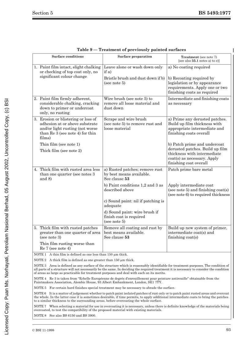
BS 5493:1977
© BSI 11-1998 93
Section 5
Table 9 — Treatment of previously painted surfaces
Surface conditions Surface preparation Treatment (see note 7) [see also 55.1 notes a) to e)]
1. Paint film intact, slight chalking or checking of top coat only, no significant colour change
Leave alone or wash down only if a)
a) No coating required
Bristle brush and dust down if b) (see note 5)
b) Recoating required by legislation or by appearance requirements. Apply one or two finishing coats as required
2. Paint film firmly adherent, considerable chalking, cracking down to primer or undercoat only, no rusting
Wire brush (see note 5) to remove all loose material and dust down
Intermediate and finishing coats as necessary
3. Erosion or blistering or loss of adhesion at or above substrate and/or light rusting (not worse than Re 3 (see note 4) for thin films)
Scrape and wire brush (see note 5) to remove rust and loose material
a) Prime any derusted patches. Build up film thickness with appropriate intermediate and finishing coats overall
Thin film (see note 1) b) Patch prime and undercoat derusted patches. Build up film thickness with intermediate coat(s) as necessary. Apply finishing coat overall
Thick film (see note 2)
4. Thick film with rusted area less than one quarter (see notes 3 and 8)
a) Rusted patches; remove rust by best means available. See clause 53
Patch prime bare metal
b) Paint conditions 1,2 and 3 as described above
Apply intermediate coat (see note 5) and finishing coat(s) (see note 6) to required thickness
c) Sound paint: nil if patching is adequate
d) Sound paint: wire brush if finish coat is required (see note 5)
5. Thick film with rusted patches greater than one quarter of area (see note 3)
Remove all coating and rust by best means available. See clause 53
Build up new system of primer, intermediate coat(s) and finishing coat(s)
Thin film rusting worse than Re 7 (see note 4)
NOTE 1 A thin film is defined as one less than 150 µm thick.
NOTE 2 A thick film is defined as one greater than 150 µm thick.
NOTE 3 Area is defined as any surface of the structure which is reasonably identifiable for treatment purposes. The condition of all parts of a structure will not necessarily be the same. In deciding the required treatment it is necessary to consider the condition of areas as large as practicable for treatment purposes and deal with each on its merits.
NOTE 4 Re 3 is taken from “Echelle Européenne de degrés d’enrouillement pour peinture antirouille” obtainable from the Paintmakers Association, Alembic House, 93 Albert Embankment, London, SE1 7TY.
NOTE 5 For certain hard finishes special treatment may be necessary to abrade the surface.
NOTE 6 It is a matter of judgement whether to patch paint isolated patches of rust only or to patch paint rusted areas and overcoat the whole. In the latter case it is sometimes desirable, if time permits, to apply additional intermediate coats to bring the patches to a similar thickness to the surrounding areas, before overcoating the whole surface.
NOTE 7 When selecting a material for use in overcoating it is necessary, unless there is definite knowledge of the materials being overcoated, to test the compatibility of the proposed material with existing materials.
NOTE 8 See also BS 6150 and BS 3900.
Lice
nsed
Cop
y: P
uan
Ms.
Nor
haya
ti, P
etro
liam
Nas
iona
l Ber
had,
05
Aug
ust 2
002,
Unc
ontr
olle
d C
opy,
(c)
BS
I

BS 5493:1977
94 © BSI 11-1998
Section 5
Table 10 — Site treatment of previously metal-coated steelworkInitial
conditionPresent condition Surface preparation Replacement
of metal where required
Paint treatment over
Sprayed metal Galvanizing
Bare metal coating
Areas of corrosion and/or some rusting of substratea
If metal is to be replaced, blast-clean
Spray metal to appropriate specification, see Table 3
Not normally necessary. If overcoating is required, see Table 3 and 11.3
If metal not to be replaced, clean corroded areas by best means available
Not applicable
Build-up cleaned areas with suitable paint system and, preferably, apply chemical-resistant finish overall
Build-up cleaned areas with suitable paint system and, preferably, apply chemical-resistant finish overall
Areas with some white corrosion products
If decoration required wash to remove salts, using stiff brush if necessary. Remove loose material with non-metallic brush
Not applicable
Apply sealing coat and chemical-resistant finish for maximum life
Apply suitable surface pretreatment followed by, preferably, chemical-resistant finish
If decoration not required, no action is necessary
Not applicable
Areas in sound condition
If decoration is required, wash to remove salts, using a non-metallic brush
Not applicable
Apply suitable paint which should be chemical-resistant for maximum life
Apply suitable surface pretreatment; follow by suitable paint which should bechemical-resistant
If decoration not required, no action is necessary
Not applicable
Sealed or painted metal coating
Areas of corrosion or some rusting of substrate
If metal is to be replaced,blast-clean
Spray metal to appropriate specification, see Table 3
See Table 3 and 11.3, consider one or two coats overall, preferably chemical-resistant
See Table 3 and 11.3, consider one or two coats overall, preferably chemical-resistant
If metal not to be replaced, remove corrosion product by best method available
Not applicable
Build-up cleaned areas with suitable paint. Apply one or two coats overall, preferably chemical-resistant
Build-up cleaned areas with suitable paint. Apply one or two coats overall, preferably chemical-resistant
Areas with some degradation of paint, dissipation of sealer, or loss of adhesion of either
Remove loose material withnon-metallic brush
Not applicable
Apply further coats of paint or sealer, preferably chemical-resistant
Apply further coats of paint or sealer, preferably chemical-resistant
Areas in sound condition
If decoration is required, dust-down
Not applicable
As above As above
If decoration is not required, no action is necessary
Not applicable
a It should be confirmed that the apparent rusting emanates from the substrate.
Lice
nsed
Cop
y: P
uan
Ms.
Nor
haya
ti, P
etro
liam
Nas
iona
l Ber
had,
05
Aug
ust 2
002,
Unc
ontr
olle
d C
opy,
(c)
BS
I

BS 5493:1977
© BSI 11-1998 95
Section 6
Section 6. Safety and health
NOTE 1 This section of the code gives recommendations for dealing with typical aspects of safety and health which arise in the work of coating iron and steel structures. It does not give complete coverage of all such aspects, because that is beyond the scope of this code. It is the duty of users of the code, in so far as they are responsible for safety and health, to ensure that all statutory requirements are met.NOTE 2 The legislative references in clauses 56 and 57 provide a holding position in view of the impending changes in legislation resulting from European Directives. The Framework Directive which will be implemented by the Proposals for Health and Safety (General Provisions) Regulations and Approved Code of Practice and other directives stemming from this means that some of the legislative references (in clauses 56 and 57) may become obsolete.
56 Legislation56.1 General. A number of Acts of Parliament contain provisions relevant to surface coating work and these should be taken into account when planning such work. The Acts should be studied directly for detail and coverage, together with any other legislation relevant to particular situations.The Health and Safety at Work etc. Act 1974 imposes a general duty on employers to protect persons at work against risks to health or safety.Note should be taken of The Control of Lead at Work Regulations 1980, The Control of Substances Hazardous to Health Regulations 1988 and the Approved Code of Practice 1988, and Carcinogenic Substances Approved Code of Practice 1988.The Noise at Work Regulations 1989 deal with the legal obligations of employers to prevent damage to hearing.56.2 Factories Act 1961. The provisions of the Factories Act 1961 and the Regulations and Orders made under the Factories Act remain in force but are now subject to the enforcement procedures of the Health and Safety at Work etc. Act 1974. The relevant provisions within the Factories Act itself include the following.
Section 131 “Prohibition of employment of women and young persons in painting buildings with lead paint”.Section 132 “Prohibitions supplementary to sections 129 to 131”.
Relevant Orders and Regulations under the Factories Act include the following.
The Factories (Cleanliness of Walls and Ceilings) Order 1960 (S.I. 1974 as amended by S.I. 1974 No 427) which states the time limits for, and the methods of, cleaning and painting factory interiors.The Construction (General Provisions) Regulations 1961 (S.I. 1580), which deal with the appointment of safety supervisors, ventilation, work adjacent to water, and the safe transport of materials.
The Construction (Working Places) Regulations 1966 (S.I. 94), which deal with scaffolding, slung scaffolding, bosun’s chairs, etc.The Construction (Health and Welfare) Regulations 1966 (S.I. 95), which deal with first aid, washing, toilet and messing facilities.The Construction (Lifting Operations) Regulations 1961 (S.I. 1581).The Protection of the Eyes Regulations 1974 (S.I. 1681 as amended by S.I. 1875 No. 303) which apply to all surface preparation (except sand papering) and spray painting.Highly Flammable Liquids and Liquefied Petroleum Gases Regulations 1972 (S.I. 917).
56.3 The Control of Pollution Act 1974. This Act covers environmental pollution such as noise and the disposal of toxic wastes.
57 Operational hazards57.1 General. Some of the operations involved in the surface protection of a structure give rise to conditions that are potentially hazardous to the structure itself and/or surrounding property, whilst others pose hazards to the health and safety of the operatives.Especially prevalent among these hazardous conditions are the furne and vapours which rise naturally by evaporation of solvents in some paints and strippers; and the pollutants which are induced by operations, such as:
a) fumes from lead-based paints when flame-cutting or flame-cleaning;b) dust from lead-based paints when rubbed-down dry;c) dust or fumes from some modern hard-setting paint;d) fumes from heating cadmium-coated components.
Caution should always be exercised in any operation which generates dust or fumes.The potential hazards of fumes are greatly increased in confined spaces where dust and fumes can accumulate and where there is little or no ventilation, for example, inside a tank or small room or between girders under a bridge deck. It should be remembered that similar conditions can also occur in the open air if the air is still and/or there is a ventilation trap. Such conditions usually necessitate the use of respirators supplying clean air and/or forced ventilation. Persons working in such conditions should be within sight of others outside the danger area. In these cases the advice of the Health and Safety Executive should be sought.
Lice
nsed
Cop
y: P
uan
Ms.
Nor
haya
ti, P
etro
liam
Nas
iona
l Ber
had,
05
Aug
ust 2
002,
Unc
ontr
olle
d C
opy,
(c)
BS
I

BS 5493:1977
96 © BSI 11-1998
57.2 Hazards to structure and surroundings. Any operation is hazardous if it involves naked flame or the production of sparks in a restricted area. In such a case, flammable vapours (arising naturally by evaporation of solvents or induced artificially by operations) can accumulate and create a risk of fire, which becomes a risk of explosion if the working space is confined or poorly ventilated. The risk of damage to the structure and surroundings in these conditions; is apparent and paralleled by the risk of injury to people nearby. Therefore such hazards should be identified and suitable precautions taken.
57.3 Risk of injury
57.3.1 Eyesight. Many of the operations involved in surface preparation produce particles which can damage the eyes directly, and dust and some types of fumes, which can also cause eye afflictions. Eye protection is essential for operatives doing such work and for those nearby.57.3.2 Hearing. Many of the operations involved in surface preparation give rise to a high level of noise. Further information is contained in the Health and Safety Executive leaflet, IND(G)75(L), Introducing the Noise at Work Regulations, a brief guide to the new requirements for controlling noise at workplaces, and in HSE Noise Guides 1 – 8.See also BS 5228.57.3.3 Respiratory system. Some of the operations of surface preparation and paint application give rise to dust or fumes which necessitate the provision of good ventilation and respiratory protection for operatives and those nearby. If other methods of controlling exposure are not possible, suitable respiratory protective equipment which is either type approved or conforms to a standard approved by HSE, should be worn. See also BS 2091, BS 4275 and HSE Guidance Notes EH 40, Occupational Exposure Limits, and EH 16, isocyanates, toxic hazards and precautions.
Some fumes, notably from cellulosic materials, not only affect the respiratory system directly but can have further unpleasant effects on the gastric system.Further advice can be obtained from the Health and Safety Executive.
58 General hygieneThe various materials encountered in dealing with old paint and applying the new paint include some that are potentially harmful, and it is therefore necessary to maintain a high level of personal hygiene. In particular, hands should be protected with silicone free barrier cream before work starts and impervious industrial gloves may be needed if heavy contamination of skin is likely. Afterwards hands and exposed areas of skin should be cleaned with an approved hand cleaner. Hands should not be cleaned with paint solvent or thinners.Overalls worn for work should be removed before eating or going home and should be laundered at frequent intervals, and all possible steps should be taken to avoid paint getting on to the skin.Some materials will require additional precautions and advice and these should be sought from the manufacturer.When operatives are working in such conditions (for example, inside a box girder) that access to toilet facilities is not quick and easy, consideration should be given to the provision of toilet facilities nearer to the work site.
Lice
nsed
Cop
y: P
uan
Ms.
Nor
haya
ti, P
etro
liam
Nas
iona
l Ber
had,
05
Aug
ust 2
002,
Unc
ontr
olle
d C
opy,
(c)
BS
I
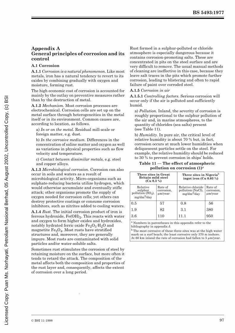
BS 5493:1977
© BSI 11-1998 97
Appendix A General principles of corrosion and its controlA.1 CorrosionA.1.1 Corrosion is a natural phenomenon. Like most metals, iron has a natural tendency to revert to its oxides by combining gradually with oxygen and moisture, forming rust.The high economic cost of corrosion is accounted for mainly by the outlay on preventive measures rather than by the destruction of metal.A.1.2 Mechanism. Most corrosion processes are electrochemical. Corrosion cells are set up on the metal surface through heterogeneities in the metal itself or in its environment. Common causes are, according to location, as follows.
a) In or on the metal. Residual mill-scale or foreign matter, e.g. dust.b) In the corrosive medium. Differences in the concentration of saline matter and oxygen as well as variations in physical properties such as flow velocity and temperature.c) Contact between dissimilar metals, e.g. steel and copper alloys.
A.1.3 Microbiological corrosion. Corrosion can also occur in soils and waters as a result of microbiological activity. Micro-organisms such as sulphate-reducing bacteria utilize hydrogen, which would otherwise accumulate and eventually stifle attack; other organisms promote the supply of oxygen needed for corrosion cells; yet others can destroy protective coatings or consume corrosion inhibitors, such as nitrites added to cooling waters.A.1.4 Rust. The initial corrosion product of iron is ferrous hydroxide, Fe(OH)2. This reacts with water and oxygen to form higher oxides and hydroxides, notably hydrated ferric oxide Fe2O3·H2O and magnetite Fe3O4. Most rusts have stratified structures and, moreover, they are generally impure. Most rusts are contaminated with solid particles and/or water-soluble salts.Sometimes rust stimulates the corrosion of steel by retaining moisture on the surface, but more often it tends to retard the attack. The composition of the metal affects both the composition and properties of the rust layer and, consequently, affects the extent of corrosion over a long period.
Rust formed in a sulphur-polluted or chloride atmosphere is especially dangerous because it contains corrosion-promoting salts. These are concentrated in pits on the steel surface and are very difficult to remove. The usual manual methods of cleaning are ineffective in this case, because they leave salt traces in the pits which promote further corrosion, leading to blistering and often to rapid failure of paint over corroded steel.A.1.5 Corrosion in airA.1.5.1 Controlling factors. Serious corrosion will occur only if the air is polluted and sufficiently humid.
a) Pollution. Inland, the severity of corrosion is roughly proportional to the sulphur pollution of the air and, in marine atmospheres, to the quantity of chlorides (sea salts) present (see Table 11).b) Humidity. In pure air, the critical level of relative humidity is about 70 % but, in fact, corrosion occurs at much lower humidities when deliquescent particles settle on the steel. For example, the relative humidity should be reduced to 30 % to prevent corrosion in ships’ holds.
Table 11 — The effect of atmospheric pollution on corrosion (1)a
Three sites in Great Britain mild steel
(Cu 0.3 %)
Three sites in Nigeriab ingot iron (Cu 0.03 %)
Relative sulphur
pollution (SO3), mg/dm2/day
Rate of corrosion, µm/year
Relative chloride pollution (NaCl),
mg/dm2/day
Rate of corrosion, µm/year
0.5 57 0.8 56
1.9 82 3.1 380
3.6 110 11.1 950a Numbers in parentheses in this appendix refer to the bibliography in appendix J.b The most corrosive of these three sites was at the high water mark on a surf beach; the least corrosive only 370 m inshore. At 60 km inland the rate of corrosion had fallen to 5 µm/year.
Lice
nsed
Cop
y: P
uan
Ms.
Nor
haya
ti, P
etro
liam
Nas
iona
l Ber
had,
05
Aug
ust 2
002,
Unc
ontr
olle
d C
opy,
(c)
BS
I

BS 5493:1977
98 © BSI 11-1998
A.1.5.2 Effect of environment. General classification, such as “rural”, “industrial” and “marine”, can be useful guides to the probable conditions at a site, especially if records are available from a nearby meteorological observatory. But for practical purposes, it is the “microclimate” immediately surrounding the structure concerned that matters. The general effects of rainfall, sunshine and atmospheric humidity are locally modified by the orientation of the steel surface, by its degree of exposure, and by the circulation of air over it. The diurnal variation in the difference between steel and air temperatures is also important, because this determines whether or not condensation occurs. The thickness of section can significantly affect the difference between steel and air temperatures.The classification of environments in respect of aggressiveness may differ according to whether it is based on the corrosion of bare steel or on the breakdown of a given protective coating. For example, although the corrosion rate in tests carried out at Sheffield was about four times that at Calshot, the durability of a paint scheme was virtually the same (see Table 12). This was because the heavy atmospheric pollution at Sheffield (largely due to smoke when the tests were made some years ago) caused rapid corrosion but also retarded actinic breakdown of paint.Table 12 — Comparison of paint performance
with the corrosion rate of bare steel (2)
A.1.5.3 Rate of corrosion in air. Under normal conditions, the rate of corrosion of an unprotected mild steel surface which is freely exposed outside in the United Kingdom is between about 25 µm per year in rural districts and about 125 µm per year in industrial districts. Overseas, the rate varies from nil to about 1 000 µm per year, the highest rates occurring in certain marine environments (see Table 11).
A.1.6 Corrosion in soilA.1.6.1 Controlling factors. Soil characteristics are the main criteria controlling the corrosion of buried iron and steel. Serious attack is more probable in disturbed soil, as when a pipe is laid in a trench, than in undisturbed soil as when a pile is driven into solid ground. Troubles can occur when steel piling with mill-scale is driven into the ground since part of the scale may be removed giving rise to a corrosion cell.The oxygen content of the soil and the drainage are most important. There is a distinction between aerobic soils, which are well aerated, and anaerobic soils, which contain no free oxygen, but some soils alternate between these conditions because of seasonal fluctuations in the water table.In aerobic soils, such as sand or chalk, air has reasonably free access to the buried metal and water can drain away readily so a layer of rust can form on the bare metal and this may retard or stifle further attack.Despite the absence of atmospheric oxygen, heavy corrosion can occur in anaerobic soils through micro-biological processes. The most important of these is the metabolism of “sulphate-reducing” bacteria which utilize hydrogen which would otherwise accumulate on the metal surface and prevent further attack (3). The necessary conditions occur in heavy clay, some waterlogged soils, harbour mud and other media such as sludge in oil tanks.The pH-value of the soil is a significant factor and, in general, acid soils are aggressive and highly alkaline ones are inert. The electrical resistance of the soil is similarly significant with the likelihood of severe corrosion decreasing as the resistance rises.A.1.6.2 Stray-current corrosion. Potential differences, such as may occur along a pipeline, can cause electric currents to enter the structure, travel along it and leave it. The (positive) current reduces or represses corrosion where it enters but aggravates corrosion where it leaves.Such conditions can occur when a pipeline or armoured cable runs through dissimilar soils, under varying soil cover, near to streams and ditches, or under a road. Corrosive currents can also originate from nearby d.c. traction systems or cathodically protected structures.
Test site Sheffield Calshot
Type of environment Industrial Marine
Rate of corrosion of mild steel over 5 years, µm/year
109 28
Life to failure of a 4-coat painting scheme, years
6.1 6.0
Lice
nsed
Cop
y: P
uan
Ms.
Nor
haya
ti, P
etro
liam
Nas
iona
l Ber
had,
05
Aug
ust 2
002,
Unc
ontr
olle
d C
opy,
(c)
BS
I

BS 5493:1977
© BSI 11-1998 99
A.1.6.3 Rate of corrosion in soil. It is not possible to generalize on corrosion in soils. Rates of 8 µm to 35 µm per year were observed in tests over 15 years in Great Britain (4). Moreover, tests carried out in America showed that corrosion generally slows down with time (5). For many structures, however, such as pipelines, the rate of pitting is the important factor, and it can be very rapid. In the most aggressive British soils, pits up to 4 mm deep have been found in pipe specimens after 15 years and an even higher rate of pitting (2.6 mm in 5 years) occurred in an embankment made up from ashes.A.1.7 Corrosion in waterA.1.7.1 Controlling factors. The corrosion rate is governed primarily by the oxygen content, the chemical composition and the temperature of the water (6).
a) Oxygen content. Most natural waters are sufficiently well aerated to ensure continuing corrosion. Rusting in many industrial waters, e.g. cooling waters, is often associated with their high oxygen content.b) Chemical composition. Natural waters vary greatly in composition. They range from certain lakes, which are almost pure water, to the concentrated brine of the Dead Sea. Estuarine waters are less saline than sea water but are often polluted.Statements in the literature on the effect of chloride concentration on the rate of corrosion are often erroneous since oxygen concentration is the main factor. In salt-spray tests there is little change in the corrosion rate over the range 0.05 % to 10 % of sodium chloride (7).The nature of dissolved solids and the amount of free and combined carbon dioxide in solution are important. Some waters deposit calcium carbonate on corroding steel at ordinary temperatures or when they are heated; others can be made to do so by chemical treatment. If, as usually happens, the calcium carbonate film has a favourable crystal structure, it will stifle further attack. Calcareous deposits of some protective value can also form on iron and steel immersed in sea water, especially when cathodic protection is applied.c) Temperature. The effect of temperature on the corrosiveness of water varies with the operating conditions but in general, rusting proceeds more rapidly as the temperature rises. In quiescent solutions the corrosion rate of iron increases by a factor of 3 to 4 on raising the temperature from ambient to about 75 °C, and thereafter the rate decreases.
A.1.7.2 Effect of flow. Water movement often accelerates corrosion by promoting the supply of oxygen to the metal surface; high water speeds may also prevent adhesion of protective corrosion products. Under adverse conditions increase of flow rates can increase corrosion rates by a factor of 100 (8).In turbulent water, damage due to corrosion is often aggravated by erosion and by cavitation. The latter can lead to the rapid destruction of dynamic components such as ships’ propellers.A.1.7.3 Other factors. The internal corrosion of steel water pipes may produce tubercles of rust, which restrict oxygen supply locally and cause corrosion by differential aeration [see A.1.2 b)]. Anaerobic conditions favourable to the growth of sulphate-reducing bacteria are established beneath these incrustations, steel then becomes severely pitted, and cast iron suffers graphitic corrosion (see A.2.2.2). Sulphate-reducing bacteria can also cause corrosion in polluted rivers and harbours and in storage tanks containing, e.g. crude oil.A.1.7.4 Rate of corrosion in water. The range of 75 µm to 125 µm per year is representative of the general wastage of mild steel in still sea water. Corrosion rates are greater in splash zones or under high flow rates, e.g. 500 µm per year. Fresh water is rather less corrosive.The rate of pitting is often much greater than general corrosion and it can be severe, especially if mill-scale is left on the steel.A.1.8 Corrosion rates of zinc and aluminium. In view of their use as protective coatings for steel, the corrosion rates of zinc and aluminium are also of interest.
a) In the open air in Great Britain, zinc corrodes at a rate which ranges from about 1 µm to 15 µm per year according to the environment (3). The same rates generally apply to zinc coatings (see Figure 1), but they do not show to advantage in sheltered, humid and sulphur-polluted conditions. The “white rusting” of galvanized steel that occurs during shipment or storage is caused by sulphur or chloride pollution in a closed and humid environment.b) Sprayed-aluminium coatings give excellent protection to steel in air: coatings 80 µm thick have been found to have lives of 20 years or more in industrial and marine environments (3). Their performance on a surf beach was outstanding (9). They are not widely used in soil although they have long life totally immersed in sea water (10).
Lice
nsed
Cop
y: P
uan
Ms.
Nor
haya
ti, P
etro
liam
Nas
iona
l Ber
had,
05
Aug
ust 2
002,
Unc
ontr
olle
d C
opy,
(c)
BS
I

BS 5493:1977
100 © BSI 11-1998
A.2 Control of corrosionA.2.1 Basic methods. There are four main methods for preventing or controlling corrosion.
a) Treating the environment.b) Insulating the steel from the environment by means of a protective coating.c) Cathodic protection.d) Attention to design (see A.3).
A.2.2 Relative corrosion resistance of different types of iron and steel. In some cases, the danger or severity of corrosion can be reduced by the choice of a more resistant metal. The characteristics of the main types of ferrous metals in this respect are summarized below.A.2.2.1 Structural steel. Structural steels manufactured by different processes corrode at substantially the same rate. The minor variations in their carbon content, analysis and microstructure have little effect.The mill-scale on hot rolled steel is a potential source of corrosion and is injurious to the performance of protective coatings; it should be removed.A.2.2.2 Cast iron. The casting skin formed on cast iron in the mould is more adherent than mill-scale and has some protective properties. If it is removed, unalloyed cast irons corrode at substantially the same rate as descaled mild steels but there is an important difference in the effects of corrosion on the two materials.Ordinary grey cast irons corrode in a peculiar way. They contain about 8 % of elements other than iron, mainly carbon in the form of graphite, phosphorus as iron phosphide, and silicon. The graphite and iron phosphide are inert and remain in situ after the iron has corroded away. The silicon becomes oxidized to silica or silicates, which help to bind the other constituents. Thus, the corrosion process leaves behind a non-metallic “graphitic corrosion residue”, which largely retains the appearance and shape of the original iron, although its mechanical strength is negligible.A.2.2.3 Low-alloy steel12). Low-alloy steels corrode more slowly than mild steel when freely exposed outdoors (11). In time their corrosion rate falls to a low value and they are designed to be used unprotected. These steels have been widely used in the bare condition in both rural and industrial environments in North America and on a small scale in the United Kingdom.
A.2.2.4 Stainless steel. The resistance of stainless steels to atmospheric corrosion far surpasses that of ordinary or low-alloy steels. The best of them, e.g. the 18/10/3 Cr-Ni-Mo type, are virtually incorrodible in dust-free air. They owe their immunity from corrosion to a thin protective oxide film, which reforms spontaneously if it is damaged but anything that interferes with this film jeopardizes the corrosion resistance. Since chlorides tend to break it down, even Cr-Ni-Mo stainless steels may become slightly rust-spotted in marine environments. The passivity of the film is also impaired if supply of oxygen to it is cut off by dust settling on the surface. Consequently, the performance of stainless steels in all types of atmosphere is greatly improved by regular cleaning, say at monthly intervals.For the same reason, stainless steels are liable to pit severely in soil, in wet timbers or in water. For example, a sheet 2 mm thick became holed within 6 months when immersed in the sea, where barnacles had settled and cut off the oxygen supply.Some stainless steels become vulnerable to stress corrosion cracking in sea water after certain methods of heat treatment. Where such a set of conditions can be foreseen the advice of a metallurgist should be sought during design.A.2.3 Protection against atmospheric corrosion. Rusting in atmospheric environments is best prevented by means of protective coatings, as has been fully discussed in the code.Dehumidification of the air (12) is an alternative or a useful adjunct in some cases (see A.3.2.2).Cathodic protection is impracticable, because of the absence of an electrolyte.A.2.4 Protection against soil corrosion. The degree of protection should match the corrosiveness of the soil.The most effective system is cathodic protection BS 7361-1 plus a protective coating. Bitumen sheathing, about 6 mm thick, or a thick coal tar pitch/epoxide coating should prove adequate in moderately corrosive soils. So should hot-dip galvanized coatings.It may sometimes be useful to replace an aggressive soil by a non-corrosive backfill, e.g. limestone or clean washed sand.
12) Those intending to use low-alloy steel should consult the British Steel Corporation.
Lice
nsed
Cop
y: P
uan
Ms.
Nor
haya
ti, P
etro
liam
Nas
iona
l Ber
had,
05
Aug
ust 2
002,
Unc
ontr
olle
d C
opy,
(c)
BS
I

BS 5493:1977
© BSI 11-1998 101
Figure 2 — Corrosion points
Lice
nsed
Cop
y: P
uan
Ms.
Nor
haya
ti, P
etro
liam
Nas
iona
l Ber
had,
05
Aug
ust 2
002,
Unc
ontr
olle
d C
opy,
(c)
BS
I

BS 5493:1977
102 © BSI 11-1998
A.2.5 Cathodic protection. Cathodic protection is a system in which an electric potential is applied from an external source to oppose the natural flow of electric current that gives rise to electrochemical corrosion. This can be done by either the sacrificial anode method or the impressed-current method. In the first case the steel is connected to a metal of lower potential, e.g. zinc, so that the zinc becomes the anode and corrodes, leaving the steel as the uncorroded cathode. In the second system the current is applied from an external d.c. source. Again the steel becomes the cathode and usually graphite is used as a permanent anode.Cathodic protection operates only in the presence of an electrolyte, and is often used to protect steel immersed in sea water and in corrosive soils. To reduce current requirements this method is generally used in conjunction with protective coatings on the steel. Only a small current is then required to protect breaks in the coating.Detailed recommendations on cathodic protection are given in BS 7361-1, but further advice should always be obtained from a specialist.
A.3 Designing for the prevention of corrosionA.3.1 Introduction. The danger of corrosion can be reduced and the efficiency of protection greatly increased by careful attention to design. Experienced designers acquire a “corrosion awareness” which enables them to eliminate potential corrosion hazards. The main points that arise are considered below under the following headings.
a) Entrapment of moisture and dirt.b) Contact with other materials.c) Coating application.d) General factors.
The choice of suitable materials of construction and of adequate protective measures is an important function of design. It has already been dealt with in the code.A.3.2 Entrapment of moisture and dirtA.3.2.1 Corrosion points. Corrosion is most likely at points where rain, condensed moisture and dust collect. To avoid such corrosion points (see Figure 2) the whole surface should be as smooth as possible, without sharp edges, sharp corners, cavities or unnecessary protuberances. Welded tubular construction has an advantage in this respect (13).
Figure 3 — Crevices
Lice
nsed
Cop
y: P
uan
Ms.
Nor
haya
ti, P
etro
liam
Nas
iona
l Ber
had,
05
Aug
ust 2
002,
Unc
ontr
olle
d C
opy,
(c)
BS
I

BS 5493:1977
© BSI 11-1998 103
A.3.2.2 Joints. Joints should be arranged to give clean uninterrupted lines. Generally, welds are preferable to bolts or rivets, butt welds to lap joints, and continuous welds to intermittent welds. If lap joints have to be used, appropriate welding or filling may be needed.A.3.2.3 Fasteners. Care should be taken in the design of fasteners and the choice of material for them (14).A.3.2.4 Friction-grip bolts. The faying surfaces of friction-grip-bolted connections need special treatment as discussed in 8.2 and 25.3.2.A.3.3 Cavities and crevicesA.3.3.1 Filling. Cavities and crevices should be avoided or, if unavoidable, filled with weld metal or mastic (see Figure 3).Any large cavities that will become inaccessible when the structure has been completed should be sealed with weld metal; where required, the seal should be tested by internal air pressure. Another method is to fill the cavities with concrete which is vibrated into position. Small spaces may be filled with mastic or rust-inhibitive paste or steel packings coated with an inhibitive paint.A.3.3.2 Box sections. If box sections can be properly sealed and tested without structural damage their internal surfaces should not need protection.If hermetic sealing is impracticable, these surfaces will be subjected to alternating condensation and evaporation of moisture. This arises from the fluctuating difference between the internal and external temperatures which causes the enclosed space to breathe. In these circumstances provision of drainage holes and painting of internal surfaces may be necessary. Non-toxic primers and light-coloured finishing coats should be used as corrosion can remain undetected beneath a dark coating such as red iron oxide paint.Protection can be prolonged by using desiccants to reduce the internal humidity. Silica-gel, used at the rate of 250 g/m3 of void, is effective for 2 to 3 years inside a reasonably well sealed structure, if the manholes are kept closed. The desiccant should be renewed at intervals and it should not be relied upon if its presence is likely to be forgotten.A.3.3.3 Tubes. In general, the remarks made in A.3.3.2 apply to tubes and hollow sections. Internal protection is seldom necessary but in doubtful cases a coating can be applied inside at the time of manufacture.
A.3.3.4 Enclosed steelwork. When steelwork is enclosed in brickwork, boarding, plaster, and other materials, it is of prime importance that the surrounding space be kept dry, i.e. below the critical humidity for corrosion [see A.1.5.1 b)]. If this cannot be done, an effective protective coating should be provided, particularly for steel surfaces in outer walls and behind dry casings for false ceilings. In some buildings, these may be exposed to process fumes.The design should carefully avoid corrosion of steel panelling on the cold side of air spaces, whether filled with insulation or not. An air space should be left between the steel and the insulation and arrangements made for warm inside air to flow up through this.A.3.4 Circulation of air, drainage, and waterproofingA.3.4.1 Circulation of air. Free circulation of air around and through the structure should be arranged (see Figure 4); this hastens the drying of surfaces after rain or dew.Protective coatings break down exceptionally quickly on sheltered surfaces, such as the eaves of buildings, where moisture lingers and such areas would benefit from the protection of special coatings.A.3.4.2 Drainage. Arrangements should be made for shedding dripping water and condensation. Where necessary, lengths of pipe should be attached to the drain holes to carry the water clear so that it cannot be blown back on to the structure [see Figure 5(a)].The design of storage tanks should permit complete drainage [see Figure 5(b)] or a sump should be provided from which condensed water can be pumped. To avoid water traps, the floor should be as smooth as possible, welded joints should be ground flush and any stiffeners should be fitted outside the plates.Extra protection should be given to the most vulnerable areas by coating the bottom and about 300 mm to 400 mm up the sides.Water traps should be avoided where steel stanchions enter the ground or are embedded in a concrete base (see Figure 6).A.3.4.3 Waterproofing. (15). Many structures, especially bridges, are made of steel and reinforced concrete. The prevention of corrosion and deterioration depends on careful waterproofing and correct design of the concrete details to keep water away from the steel.
Lice
nsed
Cop
y: P
uan
Ms.
Nor
haya
ti, P
etro
liam
Nas
iona
l Ber
had,
05
Aug
ust 2
002,
Unc
ontr
olle
d C
opy,
(c)
BS
I

BS 5493:1977
104 © BSI 11-1998
A.3.5 Contact with other materialsA.3.5.1 Other metals. Electrochemical corrosion can appear at contact surfaces between different metals.13)
Some metals, e.g. nickel and copper, aggravate the corrosion of steel while others, e.g. zinc, reduce it. The danger of bimetallic corrosion is most serious for immersed structures but should also be considered when designing atmospheric or buried structures. The latent corrosion cell can be made inert by one or more of the following methods.
a) Insulating the contact surfaces.b) Making the joints watertight and using an impermeable coating to keep out the electrolyte, e.g. rain water.c) Applying a metallic coating to the steel, so as to reduce the potential difference between it and the non-ferrous metal.d) Imposing overall cathodic protection.
A.3.5.2 Different types of steel. Contacts between mild steels and/or low-alloy steels will not affect corrosion appreciably, if they are free from mill-scale. Trouble might arise, however, at contacts between these steels and stainless steels.
A.3.5.3 Concrete. Portland cement concrete tends to inhibit the corrosion of embedded steel but it will not protect steel which is near the surface against corrosive attack. This subject is too complex to discuss in detail and is outside the scope of this code. In general, steel that is embedded in Portland cement concrete needs no additional protection if the provisions of all the parts of BS 8110 are followed. These include the following:
a) Correct composition and compaction of the mix.b) Adequate depth of cover of the reinforcement at all points. From 50 mm to 60 mm is recommended for the most severe conditions, e.g. exposure to sea water, but 20 mm may be sufficient for indoor work. There is evidence that these figures can be reduced by 25 % if the steel is given a zinc coating of 500 g/m2. The depth of cover should also be related to the maximum size of concrete aggregate.
The concrete cover should be continuous. If gaps are left in it, a corrosion cell may be set up (see Figure 7).
13) See PD 6484.
Figure 4 — Air circulation e.g. pipeline support
Figure 5 — Drainage
Lice
nsed
Cop
y: P
uan
Ms.
Nor
haya
ti, P
etro
liam
Nas
iona
l Ber
had,
05
Aug
ust 2
002,
Unc
ontr
olle
d C
opy,
(c)
BS
I

BS 5493:1977
© BSI 11-1998 105
A.3.5.4 Timber. Where steel is in contact with timber under corrosive conditions, the faces of both materials should be coated with hot tar or with a bitumen bedding compound containing fillers, immediately before they are brought together. An insulating sheet of plastic, e.g. polyethylene, may be used, especially if the timber has been treated with preservative.Large washers of neoprene or similar material should be fitted under nuts and bolt-heads to prevent water entering the wood. The nuts and bolt-heads should be coated in the same way as the bolts.Contact surfaces between zinc-coated or aluminium-sprayed steel and wood need similar treatment.A.3.5.5 Other materials. Some other building materials, e.g. gypsum plaster, are corrosive. Suitable insulation, such as a waterproof membrane, should be provided where steel touches them and the penetration of water to the interface should be prevented.Problems can also arise through the evolution of corrosive vapours from plastics and other organic materials.
A.3.6 Coating applicationA.3.6.1 General. The designer should strive to ensure that the protective coatings can be applied with ease and efficiency, so as to achieve a continuous, uniform coating everywhere. Consequently, details such as back-to-back angles, recesses, deep corners and blind holes should be avoided (see Figure 8).Sharp edges and corners cannot be coated evenly and coatings there are particularly vulnerable to damage; all edges and corners should therefore be radiused. Tubular sections are better than I or H sections in this respect.A.3.6.2 Galvanizing. Vent holes and drain holes should be provided in assemblies that are to be hot-dip galvanized (see BS 4479). They serve to avoid internal pressures and airlocks during immersion, which may cause explosions. They also ensure that molten zinc is not retained in pockets on withdrawal.
Figure 6 — Protection of a stanchion at ground level
Lice
nsed
Cop
y: P
uan
Ms.
Nor
haya
ti, P
etro
liam
Nas
iona
l Ber
had,
05
Aug
ust 2
002,
Unc
ontr
olle
d C
opy,
(c)
BS
I

BS 5493:1977
106 © BSI 11-1998
Figure 7 — Corrosion at gap in surrounding concrete
Lice
nsed
Cop
y: P
uan
Ms.
Nor
haya
ti, P
etro
liam
Nas
iona
l Ber
had,
05
Aug
ust 2
002,
Unc
ontr
olle
d C
opy,
(c)
BS
I

BS 5493:1977
© BSI 11-1998 107
Figure 8 — Design for coating
Figure 9 — Access for maintenance
Lice
nsed
Cop
y: P
uan
Ms.
Nor
haya
ti, P
etro
liam
Nas
iona
l Ber
had,
05
Aug
ust 2
002,
Unc
ontr
olle
d C
opy,
(c)
BS
I

BS 5493:1977
108 © BSI 11-1998
A.3.6.3 Dip-painting. The details of steelwork that is to be dip-painted should resemble those for hot-dip galvanized steel (see A.3.6.2).A.3.6.4 Metal-spraying. Sufficient access should be provided to all surfaces that are to be metal-sprayed (see BS 4479).A.3.6.5 Spray-painting. The paint-spraying gun is more flexible and wieldy than the metal-spraying pistol, so the details recommended for metal-spraying (see BS 4479) should be adequate for spray-painting.A.3.6.6 Access. The design should ensure easy access to all parts of the structure and thereby make it possible to inspect and renew the protective scheme without difficulty. Thus, any falsework, screens or hoardings that would impair access to the corrected structure should be easily removable.Lack of forethought, may result in areas that can be painted in the shop becoming inaccessible later (see Figure 9).Where the expense is justified, the design might include special fittings for the attachment of painting gantries or powered platforms and of awnings to shield maintenance work from bad weather. These should be robust and placed where they can be maintained without risk of accident.A.3.7 General factorsA.3.7.1 General design of the structure. The general design of the structure can affect the performance of a protective scheme.
a) It is much easier to protect large flat areas than more complicated shapes. For example, truss types of bridge are more susceptible to painting difficulties than beam and girder types and it is easier to protect tubular construction than lattice work. Tubes may be better than wires for guys and similar supports.b) Sometimes, part or the whole of a structure can be made detachable. It may then be economic to have them hot-dip galvanized and returned for re-galvanizing when necessary.
A.3.7.2 Load-bearing members. If the design permits, the load-bearing members should be located where the corrosive conditions are least intense. For example, the members supporting the roof of a tank for corrosive chemicals should be external to the tank.
A.3.7.3 Services. The locations of service pipes, cables and ducts attached to the structure, or passing through box girders, should be agreed with all interested parties before detail drawings are prepared.Lack of attention to such matters can lead to the creation of corrosion points, which arise, for example, where pockets are formed by not keeping conduits clear of the steelwork or where steam and other exhausts from pipes are allowed to impinge on it. The time needed for maintenance is uneconomically prolonged if service equipment has to be moved before the work can begin.A.3.7.4 Faying surfaces. Coatings on faying or flexing surfaces are particularly vulnerable to damage. For example, the failure of outdoor pipelines is most frequently due to the abrasion of the coating through the expansion and contraction of bearing surfaces. One possible remedy is to provide graphite pipe slides.A.3.7.5 Cathodic protection. Where cathodic protection (see BS 7361-1) is to be applied, the design should ensure good electrical continuity throughout and, if necessary, insulation from neighbouring structures. Permanent and readily accessible insulated test leads should be fitted at representative points for checking the efficiency of the insulation.
Lice
nsed
Cop
y: P
uan
Ms.
Nor
haya
ti, P
etro
liam
Nas
iona
l Ber
had,
05
Aug
ust 2
002,
Unc
ontr
olle
d C
opy,
(c)
BS
I

BS 5493:1977
© BSI 11-1998 109
Appendix B Characteristics of paint bindersB.1 Binders for drying-oil-type protective systems
B.2 Binders for one-pack chemical-resistant protective systems
Description Characteristics
Blend of raw and processed drying oils Very slow drying; good surface wetting where steel cannot be well cleaned
Drying oil modified with phenolic or phenolic-modified resin
Good water resistance; suitable for primers and undercoats but yellows in light-coloured finishes
Alkyd or modified alkyd Good all-round properties; 4 h to 8 h overcoating in good conditions depending on oil content (oil length). Prone to blistering in damp conditions
The modification may be:
a) blending with raw or processed drying oil
Dries faster than blended oils alone, but slightly less tolerant of poor surface cleaning
b) copolymerizing with styrene or vinyl toluene
Faster-drying alkyd but less tolerant of poor surface cleaning. Vinyl copolymers are sensitive to solvents and recoating times are critical
c) combining with an isocyanate to form a urethane alkyd
Basis of one-pack polyurethanes. Components are usually selected to provide additional hardness to the finish
Alkyd modified with chlorinated rubber
Faster-drying alkyd with improved water resistance. Fair chemical resistance when ratio of chlorinated rubber to alkyd is 2 : 1 or more
Solution blends in suitable solvents. Full chemical resistance and suitability for use with cathodic protection is doubtful while saponifiable component is presentChosen alkyd should be fully
compatible with the chlorinated rubber.
Drying-oil epoxy ester Faster drying than modified drying oil, with good water resistance, but yellows in light-coloured finishes(one-pack epoxy)
Urethane oil Drying-oil film is hardened and toughened. Used for primers required to withstand rough handling
drying oils suitably modified with isocyanates
Silicone alkyds When silicone resin content exceeds 30 %, alkyd is durable and retains gloss. Especially recommended for finishing coats exposed to intense sunlight
Description Characteristics
Blend of chlorinated rubbers and non-saponifiable plasticizers.NOTE For blends with alkyds see B.1 “alkyd modified with chlorinated rubber”.
Very low water permeability. Quick drying. Can be overpainted with no adhesion problems, even after prolonged aging
Blend of vinyl chloride/acetate copolymers with or without non-saponifiable plasticizersNOTE Primers with copolymer should be maleic modified to assist adhesion.
Similar to preceding binder but much less tolerant of poor surface cleaning and has a higher water-vapour permeability. More durable in finishing coats exposed to intense sunlight. Low-build at normal viscosity
Lice
nsed
Cop
y: P
uan
Ms.
Nor
haya
ti, P
etro
liam
Nas
iona
l Ber
had,
05
Aug
ust 2
002,
Unc
ontr
olle
d C
opy,
(c)
BS
I

BS 5493:1977
110 © BSI 11-1998
B.3 Binders for two-pack chemical-resistant protective systems(For correct use of the terms “binder”, “vehicle”, “medium”, see BS 2015.)
B.4 Binders for specific uses in protective systems
Description Characteristics
Two-pack epoxy The epoxy resin is available at different viscosities (low viscosity for high build). The curing agent is either an amine or an amide. The reaction on mixing is temperature dependent and results in a highly chemically resistant binder. Amines, especially aliphatic amines, can be toxic until reacted and should be used with great care. The choice of curing agent also depends on required performance. Paint manufacturer’s advice should be sought in every case
mixture of an epoxy resin and suitable curing agent
Curing agentsaromatic amines Good water resistance and low-temperature curealiphatic amine adducts Good speed of cure and solvent resistance, but tend to give poor
intercoat adhesionaromatic amine adducts Good intercoat adhesion and resistance to aqueous chemicalspolyamides Slower curing rate and good pot life, best when blended with coal
tarCoal tar epoxy Coal tar is a diluent and cheapening additive which detracts little
from general properties and gives slightly better water resistance. It is not satisfactory for solvent resistance and gives poor low-temperature flexibility. Recoating periods are critical and this leads to intercoat adhesion problems and a tendency to bleed into subsequent coats
mixture of an epoxy resin with a suitable coal tar fraction
Two-pack polyurethane The polyester can vary from brittle to flexible; blends are made to suit finish requirements
mixture of suitable polyester resins with polyisocyanate curing agent,aliphatic polyisocyanate Superior colour retention and UV-resistance; recommended for
finishing coataromatic polyisocyanate Suitable for primers, undercoats and finishes. Not used where it
is important to avoid yellowingNOTE Two-pack polyurethanes have better weathering resistance and low-temperature cure than two-pack epoxies but are more difficult to formulate for high-build products and, during curing, are more sensitive to moisture.
Description Characteristics
Polyvinyl butyral resinsa) For two-pack pretreatment primer (see product sections of Table 4)
When mixed, the phosphoric acid reacts with resin and the metal surface to give a chemical bond. May be modified with phenolic resin for improved water resistance
b) For single-pack “blast primer” (see product sections of Table 4)
Modified with phenolic resin
Silicone resin In the skeleton of the binder, silicon replaces the more usual carbon. This adds heat resistance to its value as a binder (e.g. aluminium silicones for steel chimney stacks)
Alkali silicates, (see product sections of Table 4)
Aqueous binder reacting with zinc-dust pigment; dries to a hard adherent cement-like structure with good abrasion resistance
Organic silicates, (see product sections of Table 4)
Alkyl ester hydrolyzing and reacting with zinc-dust pigment; dries to a hard adherent cement-like structure with good abrasion resistance. More tolerant than alkali silicates to variations in atmospheric moisture
Lice
nsed
Cop
y: P
uan
Ms.
Nor
haya
ti, P
etro
liam
Nas
iona
l Ber
had,
05
Aug
ust 2
002,
Unc
ontr
olle
d C
opy,
(c)
BS
I

BS 5493:1977
© BSI 11-1998 111
Appendix C Characteristics of paint pigmentsC.1 Pigments used mainly for primers
C.2 Laminar pigments used mainly for undercoats and finishes
C.3 White pigments for undercoats and finishes
Description Characteristics
Red lead(also red/lead white/lead)
Suitable where oil content of binder is high(i.e. slow drying)
Zinc chromate Available with different degrees of solubility. Solubility can inhibit corrosion but may also cause blistering. Paint manufacturer should be consulted before use
Zinc tetroxychromate Used in pretreatment primer with polyvinyl butyral resin binder (see table A)
Zinc phosphate Good general-purpose pigment for primers. Its light colour is an advantage if producing light tints; early rusting caused by thin films or overexposure can be seen
Metallic lead Satisfactory performance for bridge protection and in paints for direct application to galvanized steel. Reactive in certain environments
More suitable than red lead for oil-free binders
Iron oxide Inert pigment of high staining power; yellow, red and black forms are suitable as a cheap additive. Use of red form in primers may mask initial breakdown by rusting
Zinc dust Gives some cathodic protection to steel when used as a sufficiently high percentage of the total film to ensure electrical conductivity through the dry paint film to the steel. See BS 4652
Calcium plumbate Used in paints for direct application to galvanized steel.See BS 3698
Description Characteristics
Micaceous iron oxide (MIO)
Mica
Aluminium All these are used in protective coatings because the flakes lie parallel to the surface and overlap, forming a moisture barrier and improving tensile strength. MIO and aluminium protect the binder from UV-degradation. Leafing aluminium has high lustre. Aluminium and graphite are used for high temperature paints. Aluminium is not recommended for chemical resistance
a) leafing, coated with stearic acid
b) non-leafing
Graphite
Stainless steel
Glass flake
Description Characteristics
Titanium dioxide (rutile) The principal white colouring pigment is rutile titanium dioxide. The anatase grade chalks on exposure to UV-light but is suitable for undercoats. A proportion of zinc oxide may be used for its antifungal and biocidal properties. A proportion of antimony oxide is used where special fire-retardant properties are required
Titanium dioxide (anatase)
Zinc oxide
Antimony oxide
Lice
nsed
Cop
y: P
uan
Ms.
Nor
haya
ti, P
etro
liam
Nas
iona
l Ber
had,
05
Aug
ust 2
002,
Unc
ontr
olle
d C
opy,
(c)
BS
I

BS 5493:1977
112 © BSI 11-1998
C.4 Coloured pigments for undercoats and finishes
C.5 Extender pigments for undercoats and finishesExtenders, as used in anticorrosive protective compositions are inorganic compounds of limited opacity and low refractive index, they may occur in nature or can be made synthetically. The choice of extender depends on the property required of the protective coating.
Description Characteristics
Iron oxides Light-resistant cheap pigments available in shades of red, yellow and black
Carbon blacks Very high staining power and, as relatively small additions, give high-opacity black finishes. As tinters they are the basis of grey finishes
Light-resistant organic or inorganic pigments
Pigments should be selected which are known to be adequately resistant to light when used with the binder specified
Light-resistant organic or inorganic pigments with good chemical resistance
The pigment as well as the binder should have the specified chemical resistance
Description Characteristics
Oxides, mainly silicas Naturally occurring as quartz (sand) and diatomaceous silicas such as kieselguhr. Synthetic silicas usually have a very fine particle size and are very transparent in binders. Sand is useful for abrasion resistance (deck and floor paints). Kieselguhr and synthetic silicas are useful in reducing gloss of finishes (e.g. to achieve matt finishes)
Carbonates
calcium carbonate (chalks, limestone whiting)
Calcium and barium carbonates are also available in synthetic form. The carbonates are cheap extenders with good all-round properties but are not suitable for acid-resistant finishes and should be avoided where the environment is considered severecalcium magnesium carbonate,
(dolomite)
barium carbonate (witherite)
Silicates
aluminium silicates (china clay, mica, bentonite)
Cheap extender, useful for anti-settling propertiesGood for producing a gel structure in formulations
calcium silicates (wollastonite, synthetic)
Alkaline in nature and stabilizes emulsion or water-based paints
magnesium silicates (talc, asbestine)
Assists suspension and controls settlement in primers and undercoats
calcium-magnesium-iron silicates (asbestos)
The fibrous nature prevents cracking of bituminous and like products
Sulphates
barium sulphate (barytes (synthetic form), blanc fixe)
Insolubility makes it an outstanding extender in high-performance formulations
calcium sulphate (gypsum (synthetic form), precipitated calcium sulphate)
Because of its water sensitivity, should be used with considerable caution
Lice
nsed
Cop
y: P
uan
Ms.
Nor
haya
ti, P
etro
liam
Nas
iona
l Ber
had,
05
Aug
ust 2
002,
Unc
ontr
olle
d C
opy,
(c)
BS
I
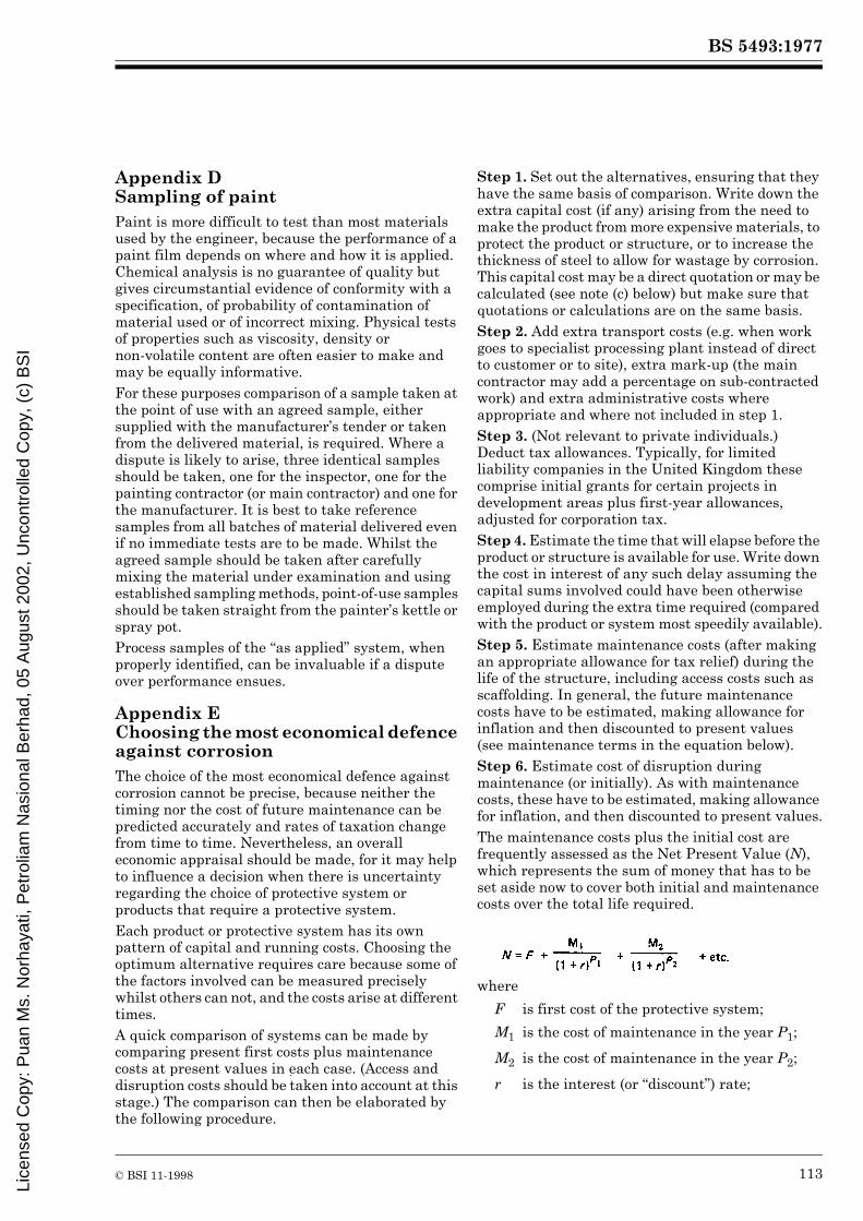
BS 5493:1977
© BSI 11-1998 113
Appendix D Sampling of paintPaint is more difficult to test than most materials used by the engineer, because the performance of a paint film depends on where and how it is applied. Chemical analysis is no guarantee of quality but gives circumstantial evidence of conformity with a specification, of probability of contamination of material used or of incorrect mixing. Physical tests of properties such as viscosity, density ornon-volatile content are often easier to make and may be equally informative.For these purposes comparison of a sample taken at the point of use with an agreed sample, either supplied with the manufacturer’s tender or taken from the delivered material, is required. Where a dispute is likely to arise, three identical samples should be taken, one for the inspector, one for the painting contractor (or main contractor) and one for the manufacturer. It is best to take reference samples from all batches of material delivered even if no immediate tests are to be made. Whilst the agreed sample should be taken after carefully mixing the material under examination and using established sampling methods, point-of-use samples should be taken straight from the painter’s kettle or spray pot.Process samples of the “as applied” system, when properly identified, can be invaluable if a dispute over performance ensues.
Appendix E Choosing the most economical defence against corrosionThe choice of the most economical defence against corrosion cannot be precise, because neither the timing nor the cost of future maintenance can be predicted accurately and rates of taxation change from time to time. Nevertheless, an overall economic appraisal should be made, for it may help to influence a decision when there is uncertainty regarding the choice of protective system or products that require a protective system.Each product or protective system has its own pattern of capital and running costs. Choosing the optimum alternative requires care because some of the factors involved can be measured precisely whilst others can not, and the costs arise at different times.A quick comparison of systems can be made by comparing present first costs plus maintenance costs at present values in each case. (Access and disruption costs should be taken into account at this stage.) The comparison can then be elaborated by the following procedure.
Step 1. Set out the alternatives, ensuring that they have the same basis of comparison. Write down the extra capital cost (if any) arising from the need to make the product from more expensive materials, to protect the product or structure, or to increase the thickness of steel to allow for wastage by corrosion. This capital cost may be a direct quotation or may be calculated (see note (c) below) but make sure that quotations or calculations are on the same basis.Step 2. Add extra transport costs (e.g. when work goes to specialist processing plant instead of direct to customer or to site), extra mark-up (the main contractor may add a percentage on sub-contracted work) and extra administrative costs where appropriate and where not included in step 1.Step 3. (Not relevant to private individuals.) Deduct tax allowances. Typically, for limited liability companies in the United Kingdom these comprise initial grants for certain projects in development areas plus first-year allowances, adjusted for corporation tax.Step 4. Estimate the time that will elapse before the product or structure is available for use. Write down the cost in interest of any such delay assuming the capital sums involved could have been otherwise employed during the extra time required (compared with the product or system most speedily available).Step 5. Estimate maintenance costs (after making an appropriate allowance for tax relief) during the life of the structure, including access costs such as scaffolding. In general, the future maintenance costs have to be estimated, making allowance for inflation and then discounted to present values (see maintenance terms in the equation below).Step 6. Estimate cost of disruption during maintenance (or initially). As with maintenance costs, these have to be estimated, making allowance for inflation, and then discounted to present values.The maintenance costs plus the initial cost are frequently assessed as the Net Present Value (N), which represents the sum of money that has to be set aside now to cover both initial and maintenance costs over the total life required.
where
F is first cost of the protective system;
M1 is the cost of maintenance in the year P1;
M2 is the cost of maintenance in the year P2;
r is the interest (or “discount”) rate;
Lice
nsed
Cop
y: P
uan
Ms.
Nor
haya
ti, P
etro
liam
Nas
iona
l Ber
had,
05
Aug
ust 2
002,
Unc
ontr
olle
d C
opy,
(c)
BS
I

BS 5493:1977
114 © BSI 11-1998
Maintenance costs are steadily rising and so have to be adjusted at present-day values (M) to allow for inflation at an annual rate r1: (r1 is expressed like r).M1 = M(1 + r1)P1 etc.Therefore:
In the simplest case, where the rate of inflation of maintenance costs is the same as the interest (or “discount”) rate available on money (i.e. where there is no time-value of money), then r1 = r and the formula is simplified to:
Other costs can be treated as for the maintenance costs or for the first cost as appropriate. Table 13 illustrates a model cost-calculation table.The following points should be borne in mind when making the necessary calculations.
a) For many protective schemes the initial cost in the factory is roughly proportional to total thickness, but life to first maintenance is not necessarily proportional to thickness; e.g. relatively thin metal coatings in certain environments often have the longest lives to first maintenance.b) Calculation of protection costs from fundamentals has been dealt with in industry-oriented handbooks, e.g. “Galvanizing for profit”, Galvanizers Association, London, UK. In principle, first costs include:
materialslabouroverheads (including inspection, access equipment and tools for painting).
These are usually of the same order of magnitude, with materials being most costly for metal coatings and labour most costly for paint coatings.
c) Surface preparation for painting is often analysed separately, for its cost frequently amounts to about one-third of the total cost. Acceptance of poor surface preparation may save 20 % or less of the total capital cost, but is likely to reduce the life expectancy of a coating by more than half, so adding more than 100 % to the total life cost. Incorrect choice of blasting equipment (e.g. size of nozzle, grade of abrasive, etc.) will increase the cost of surface preparation and may even double it.d) In calculating paint quantities, the theoretical dry-film requirement should be increased by up to 50 % to allow for locally thick coatings, wastage, repairs and losses (typically 30 % for air spray, 15 % for airless spray, 10 % for electrostatic spray, 5 % for roller or brush application) etc. Manufacturers should be asked to quote the percentage of solids by volume in their paints to facilitate calculations.e) Labour costs for the application of paint increase in an approximate ratio in the following order:
f) Comparative costs, unlike actual costs, change little with time. When labour costs are rising more rapidly than material costs, painting will become slightly more expensive relative to metal coatings and vice versa.
NOTE 12 % rate is written 0.12, etc. r can also be the expected rate of return on capital employed in the business.
P1 denotes the number of years to first maintenance;
P2 denotes the number of years to second maintenance, etc.
N = F + the sum of all maintenance costs at present-day rates
= the aggregate of all initial and maintenance costs at present-day rates
airless spray : normal air spray : roller : brush
1 : 2 : 3 : 4
Figure 10 — Shop coating costs relative to thickness of steel
Lice
nsed
Cop
y: P
uan
Ms.
Nor
haya
ti, P
etro
liam
Nas
iona
l Ber
had,
05
Aug
ust 2
002,
Unc
ontr
olle
d C
opy,
(c)
BS
I

BS 5493:1977
© BSI 11-1998 115
Table 13 — Suggested layout of a cost-calculation table
g) Sprayed-metal, paint, powder, and tape coatings are usually costed by the area covered, which should be known reasonably accurately. Galvanizing is costed by the weight of steel coated, i.e. by the thickness of steel. Costs also vary by product. The qualitative relation for structural steel is shown in Figure 10.h) The most economical system for one job is not necessarily the most economical for another, e.g. galvanized steel may be best for a bolted job but not where much site welding is necessary.i) First costs include access costs, e.g. scaffolding. Surfaces treated before erection do not require scaffolding.
Appendix F Methods for control of preparation (by blast-cleaning)Grades of blast-cleaning are selected by the specifier in relation to the conditions of use and the protective system chosen. Specifications for blast-cleaning are given, together with representative photographic examples, in Swedish Standard SIS 05 59 00 and BS 7079-A1, but these can be used for site control only if the lighting is good and the inspectors are highly experienced. Steel coupons blast-cleaned to an agreed standard are better but should be carefully stored and handled to prevent deterioration.
For convenience and to reduce disputes it is best to use instruments which enable figures to be recorded. A light reflectometer, e.g. the Surclean Model 15314), can be used to assess effectiveness of removal of mill-scale, freedom from rust, and general approach to “white metal” condition. This instrument measures the amount of blue light reflected from the surface compared with that from a standard grey tile. Repeatedly blasting the same area of steel causes an increase in reflection until a steady value Rmax is reached corresponding to white metal (dependent on the abrasive and the steel) as shown in Figure 11. The acceptance level should be fixed as a percentage of Rmax for BS 7079-A1, Sa2½; the average of all readings on the work should be at least 90 % of Rmax and not more than one reading in ten should be below 80 % of Rmax. When using this control method the value of Rmax and the acceptance levels should be agreed by the Inspector, the contractor and other interested parties at the start of the work.
Competing systems(conforming to systems under same environment and same
time to first maintenance in Table 3)
First system Second system etc.
Extra capital cost (step 1)
Add extra transport costs (step 2)
Add extra fabricator’s mark-up (step 2)
Total gross extra capital cost
Deduct total taxed allowances (step 3)
Total gross extra capital cost, net of tax allowances, etc.
Delay factor (step 4)
Maintenance costs (step 5)
Disruption factor (step 6)
Total cost of system, over and above costs common to all systems, and expressed in present-value terms
14) Supplied by Elcometer Instruments Ltd., Manchester.
Lice
nsed
Cop
y: P
uan
Ms.
Nor
haya
ti, P
etro
liam
Nas
iona
l Ber
had,
05
Aug
ust 2
002,
Unc
ontr
olle
d C
opy,
(c)
BS
I

BS 5493:1977
116 © BSI 11-1998
Appendix G Test for detecting soluble rust-producing salts remaining on blast-cleaned steelWhen blast-cleaning heavily rusted and rust-pitted steel a surface appearance suggesting a standard of cleanness equivalent to white metal or Swedish Standard Sa2½ or Sa3 can be obtained, which, after an hour or two and sometimes after standing overnight, develops rust-spotting at points corresponding to the rust-pitting. In such circumstances it is a serious mistake to apply protective coatings until the cause of the rust-spotting has been eliminated. The cause is the presence of rust-producing soluble salts of iron which are practically colourless and are located at the lowest point of the rust pits. In the presence of moisture they hydrolyse to iron oxides and acids; the acids dissolve more iron to form more iron salts thus producing, in time, large volumes of rust which will break the adhesion bond of protective coatings if applied before the salts are removed.
Using potassium ferricyanide test papers any remaining soluble iron-salt contaminants can be detected as follows.
a) Spray a fine mist of water droplets on to a small area of the blast-cleaned surface using a hand spray (a scent-spray type of bottle if satisfactory).b) Allow the water droplets to evaporate and at the moment when they have disappeared but the surface is just perceptibly wet apply a small piece of test paper and press with the thumb for 2 to 5 seconds.If soluble salts remain, these will be drawn by capillary action into the test paper and will react with the potassium ferricyanide to give a characteristic prussian blue complex as blue dots on the paper corresponding to the contaminated pits on the blast-cleaned steel.
Appendix H Example of use of the code (see clause 3)The following example is intended to demonstrate, for the inexperienced specifier, the step-by-step approach to selection of a coating system for a particular fabrication, taking all appropriate factors into account.The protective system to be selected and specified is required for a girder linking a sea-water pontoon to a fixed point on land at a site in the United Kingdom.It is assumed that the girder has been conceived as a welded box-girder with lightening holes and pin joints at the ends. The pin joints, which are considered to be purpose-made units to be attached to the ends of the girder by site bolts, are not included in the example.
Figure 11 — Assessment of steel cleaning
Lice
nsed
Cop
y: P
uan
Ms.
Nor
haya
ti, P
etro
liam
Nas
iona
l Ber
had,
05
Aug
ust 2
002,
Unc
ontr
olle
d C
opy,
(c)
BS
I

BS 5493:1977
© BSI 11-1998 117
The selection and specification of a coating system Source of information or location in the code
Step 1 Acquire an appreciation of what is included in the code and where it is located
Table of contents and index
Step 2 Consider if any modification of the design is desirable in the light of the advice in the code
45.3 and A.3
In the example it is seen that a box section with lightening holes will not only trap water but will be difficult to maintain internally, so it is decided to redesign the girder as a welded plate girder with lightening holes in the web. This reduces water trapping and makes all surfaces readily accessible.Special attention is paid to the ends to ensure that any water resting on the bottom flange can run off as the pontoon rises and falls.
Step 3 Ascertain and list the basic facts concerning the structure by answering the questions in 4.2In the example, the facts (and assumptions) are tabulated as follows.4.2.1 Function.
a) Structure is required to link pontoon to shore. Design remitb) Nil.
4.2.2 Life.a) 50 years.
Design remitb) Reconsider later.
4.2.3 Environment. Clause 5a) Coastal.b) Structure is a few feet above salt water and is likely to be covered with spray from time to time.c) At high tide, in storm conditions the under side may be hit by water-borne flotsam, but there is unlikely to be mechanical damage arising from usage or contamination by de-icing salts.
Design remit
4.2.4 Appearance.a) The owning authority requires the colour to be green overall. Design remitb) Yes.
4.2.5 Special properties.a) No requirement.
4.2.6 Maintenancea) Because of pontoon use, access for maintenance will be possible only in November and December.
Design remit
b) It is clear that maintenance will be difficult. Practical experience
4.2.7 Health and safety.a) No special points requiring attention are apparent at this stage.b) The existence of offices adjacent to the shore connection suggests that limits may be placed on permissible noise and/or dust created during maintenance work.
Section 6 and practical experience
4.2.8 Tolerance.a) A high standard is essential at this site, requiring works application of initial coatings.
Clause 9
b) As a) above. However, site applied coats may need to be tolerant of a lower standard.
Suppliers
Lice
nsed
Cop
y: P
uan
Ms.
Nor
haya
ti, P
etro
liam
Nas
iona
l Ber
had,
05
Aug
ust 2
002,
Unc
ontr
olle
d C
opy,
(c)
BS
I

BS 5493:1977
118 © BSI 11-1998
The selection and specification of a coating system Source of information or location in the code
Step 4 Examine Table 1. Select the description nearest to 4.2.3 above. Turn to the corresponding part of Table 3
Table 1
In the example, the nearest description is “sea water: splash zone ... frequent salt spray”.
Table 3, part 9
Step 5 Decide on a life requirement, taking into account the answers to questions 4.2.2, 4.2.4, 4.2.6
Clause 6
It is clear that a durable protective system is required. However, the decorative coating may be expected to require attention at shorter intervals than would normally apply with a durable protective system. It is decided, therefore, to select a “long life” system to reduce the frequency of maintenance and (incidentally) reduce the likelihood of potentially noisy surface preparation being needed for corroded areas. At the same time a greater frequency of maintenance for the decorative coating is considered acceptable.
6.2.1
6.2.2
6.3 b)
Step 6 Consider the “long life” systems listed in Table 3, part 9; eliminate any that are thought to be unsuitable. Make preliminary estimates of the approximate cost per square metre and inquire into the suitability (for the actual conditions) of the remaining systems, so far as time permits
Table 3, part 9. Appendix E
It is clear that some of the systems listed (SB1 + SK5; SB3; SB9; SC3Z; SC6Z; SC10A; SC10Z; SE7; SK8; SL5) will require the decorative finish as an addition; yet there are no immediately obvious reasons for eliminating any of those systems at this stage. Therefore:
a) if time permits, make inquiries (preferably of the manufacturers) about all of these systems; or
b) if there is not sufficient time, confine the inquiries to those systems that include a finish that gives or seems to give the required appearance.
Step 7 On the basis of the conclusions reached in step 6 and any experience or justified preference, select a limited number of systems for detailed examination
In fact, time is short (step 6 b) applies) so the selection of systems for detailed study is limited to SB9; SC10A; SC10Z; SE7; SL5.
Table 3, part 9
Step 8 Make a detailed study of the characteristics of the selected systems, asking the questions listed in 4.3
In this example, this study could have been made as part of step 6 because the time limitation discussed in step 7 was then already known.
4.3
A check list in the following form may be found useful. It tabulates the answer for each of the five systems against each question.
4.3.1 Coating systems.
a) SB9 SC10A SC10Z SE7 SL5 Table 3, part 9
b) Yes Yes Yes Yes Yes Supplier/experience
c) Yes Yes Yes Yes Yes Supplier/experience
d) Application method to suit material. No apparent limitation.
Lice
nsed
Cop
y: P
uan
Ms.
Nor
haya
ti, P
etro
liam
Nas
iona
l Ber
had,
05
Aug
ust 2
002,
Unc
ontr
olle
d C
opy,
(c)
BS
I

BS 5493:1977
© BSI 11-1998 119
The selection and specification of a coating system Source of information or location in the code
4.3.2 Coating facilities
SB9 SC10A SC10Z SE7 SL5
a) 1) Depends on size and shape of structural member
Yes Yes Yes Yes Supplier/experience
2) Yes Yes Yes Yes Yes Supplier/experience
b) Very large members may be a problem
Yes Yes Yes Yes
c) Yes Yes Yes Yes Yes
d) Yes Yes Yes Yes Yes
4.3.3 Compatibility
SB9 SC10A SC10Z SE7 SL5 Clauses 7 and 8
a) Yes Yes Yes Yes Yes
b) Not with normal structural steels; check if special steels may be used in the fabrication
No No No No
c) N.A. (not applicable)
4.3.4 Delays.
SB9 SC10A SC10Z SE7 SL5
a) N.A. N.A. N.A. N.A. N.A.
b) N.A. N.A. N.A. N.A. N.A.
c) N.A. N.A. N.A. There may be problems of intercoat adhesion.
d) N.A. N.A. N.A. There may be problems of intercoat adhesion.
e) The final coat should be applied as soon as possible after erection in view of possible salt contamination. Ensure adequate pretreatment before applying paint coat.
4.3.5 Transport, storage, handling (works-applied coats only).
SB9 SC10A SC10Z SE7 SL5
Experience applied to manufacturer’s data
a) Quite good Good Good Fair Fair
b) Quite good Good Good Fair Fair
c) Good Good Good Doubtful Doubtful
d) N.A. N.A. N.A. N.A. N.A.
NOTE These are qualitative, not absolute, terms.
4.3.6 Experience.
Assumed reported equal for all systems.
4.3.7 Export.
Not applicable.
Lice
nsed
Cop
y: P
uan
Ms.
Nor
haya
ti, P
etro
liam
Nas
iona
l Ber
had,
05
Aug
ust 2
002,
Unc
ontr
olle
d C
opy,
(c)
BS
I

BS 5493:1977
120 © BSI 11-1998
The selection and specification of a coating systemSource of
information or location in the code
4.3.8 Maintenance.
Yes, if steel is exposed. Deterioration of finishing coat only is not serious.
4.3.9 Costs.
a) 1)It is not practical to quote costs in a hypothetical exercise.
2)
3)So far as can be seen these will be the same for all the systems considered.
4)
b)
Step 9 Make final selection
In the example, all five systems examined are of about equal merit. Assuming that there is no large disparity in the Net Present Value of the corrosion protection, it is decided to reduce the choice to the two sprayed-metal systems, since these seem to have some slight advantage.
Step 10 Review the design in the light of the information now assembled
No further basic modification of the design seems necessary. However, detailing should ensure adequate access for surface preparation and application of coatings, with provision for slinging.
Step 11 Draft the Specification for inclusion in the tender documents
It may be advantageous to permit the contractor to include alternative prices in his tender for different systems where the performance is equal.
The specifications for these items are based on the recommendations included in this code. The clauses for fabrication, handling, transport, storage and erection of steelwork cover all necessary precautions.
Section 3
Full details of the protective system are given, including references to British Standards; and clauses covering quality of other materials, standards of workmanship and limitations on application environments are included.
Section 2
Section 3
Step 12 Draft the inspection requirements Section 4
Since undetected or unrepaired damage to the coating system can have serious consequences it is considered necessary to specify “full” level inspection for both works- and site-applied coats.
4.3.8
Clause 37
Furthermore, it is required that all inspection reports and other relevant information be kept available for future reference in connection with maintenance.
Clause 39
Step 13 Final-check Clause 34
Lice
nsed
Cop
y: P
uan
Ms.
Nor
haya
ti, P
etro
liam
Nas
iona
l Ber
had,
05
Aug
ust 2
002,
Unc
ontr
olle
d C
opy,
(c)
BS
I

BS 5493:1977
© BSI 11-1998 121
Appendix J References and bibliographyJ.1 References cited in appendix A(1) Hudson, J.C., and Stanners, J.F. The effect of climate and atmospheric polution on corrosion. Journal of Applied Chemistry, vol. 53, 1953, pp. 86–95.(2) Sixth Report of the Corrosion Committee. Special Report No. 66. London: Iron and Steel Institute, 1959.(3) Booth, G.H. Microbiological corrosion. London: Mills and Boon, 1971.(4) Hudson, J.C., and Watkins, K.O. Tests on the corrosion of buried cast-iron and mild-steel pipes. BISRA Open Report MG/B/3/68. British Iron and Steel Research Association, 1968.(5) Romanoff, M. Underground corrosion. National Bureau of Standards Circular 579. Washington, D.C.: U.S. Government Printing Office, 1957.(6) Corrosion of iron and steel by industrial waters and its prevention. Special Report No. 41. London: The Iron and Steel Institute, 1949.(7) Bishop, R.R. Costly car rot can be slowed. London: New Scientist, vol. 62, 1974, pp. 380–3.(8) Butler, G., et al. The influence of movement and temperature on the corrosion of mild steel. Journal of Applied Chemistry, vol. 10, 1960, pp. 80–93; vol. 15, 1965, pp. 325–8.(9) Stanners, J.F. Metal coatings on steel at Lighthouse Beach, Lagos. British Corrosion Journal, vol. 6, 1971, pp. 197–9.(10) Scott, D.J. Aluminium sprayed coatings: their use for the protection of aluminium alloys and steel. Transactions of the Institute of Metal Finishing. London, vol. 49, 1971, pp. 111–22 and 173–5.(11) Chandler, K.A., and Kilcullen, M.B. Corrosion-resistant low-alloy steels: a review with particular reference to atmospheric conditions in the United Kingdom. British Corrosion Journal, vol. 5, 1970, No. 1, pp. 24–32.(12) Gates, P.H. Corrosion prevented by humidity control. Conference on heavy-duty coatings, 1972. Institution of Corrosion Technology.(13) Godfrey, G.B. The design and protection of tubular structures. Symposium on the Protection of Structural Steelwork. London: Zinc Development Association, 1962.(14) White, P.E. The selection and use of corrosion resistant fasteners for building construction. Symposium on Developments in Methods of Prevention and Control of Corrosion in Building. November 1966, British Iron and Steel Federation.(15) Waterproofing concrete bridge decks. Paris: O.E.C.D., 1972, obtainable from H.M.S.O.J.2 BibliographyDepartment of Industry. Corrosion prevention directory. London: H.M.S.O., 1975.Shreir, L.L. (ed.). Corrosion (2 vols). London: Newnes-Butterworths, 2nd edition, 1976.Evans, U.R. The corrosion and oxidation of metals. London: Arnold, 1960.Evans, U.R. first supplementary volume. London: Arnold, 1968.Evans, U.R. second supplementary volume. London: Arnold, 1976.Barton, K. (translated by J.R. Duncan). Protection against atmospheric corrosion. London: Wiley, 1976.American Society for Testing and Materials. Metal corrosion in the atmosphere. Philadelphia, Special Technical Publication No. 435, A.S.T.M., 1968 (obtainable from University Microfilms, High Wycombe, England.)Chatfield, H.W. (ed.). The science of surface coatings. London: Ernest Benn, 1962.Fancutt, F., et al. Protective painting of structural steel. 2nd edition. London: Chapman Hall, 1968.Morgan, M.A. Cathodic protection. London: Leonard Hill, 1959.Slunder, C.J., and Boyd, W.K. Zinc: its corrosion resistance. London: Zinc Development Association, 1971.Zinc Development Association. Galvanizing Guide. London: Zinc Development Association (re-issued at frequent intervals).
Lice
nsed
Cop
y: P
uan
Ms.
Nor
haya
ti, P
etro
liam
Nas
iona
l Ber
had,
05
Aug
ust 2
002,
Unc
ontr
olle
d C
opy,
(c)
BS
I

BS 5493:1977
122 © BSI 11-1998
Index
In this index references are not to page numbers but to clause, table, figure and appendix numbers. The method of alphabetization used is word-by-word. The use of bold type denotes that the reference is wholly concerned with the subjects to which they refer.Abrasion 12.1.6; Table 1; Table 3, part 18, note e)Abrasion resistance 10.2; 11.3.1; 13.1; 24.1; Table 3, note e)Abrasive additives (to paint) 8.2; Table 3, part 18Abrasives see Blast-cleaningAccess 29; A.3.6.6
classification 29design of 7; Table 4A to Table 4M, note i)gantries A.3.6.6impossibility of 6.1insufficient 22.3; 29; 46.3.2maintenance 6.1; 6.3; 33.1; 46.3.2; 47.2; A.3.6.6platforms A.3.6.6safety 23.9; 56; A.3.6.6
Acetate copolymers see Binders and vehicles; ModifiersAcid-pickling 14.3.2; 16.2.2
bolts 25.2Duplex process 14.3.2; 16.2.2.1Footner process 14.3.2; 16.2.2.1overpickling see Defectspotential defects Table 8Cstandards 16.2.2.1
Acidity 11.3.1; Table 1Actinic breakdown A.1.5.2Additives see also Coatings; Modifiers
bactericidal Table 3, part 19flake aluminium 12.6.3inhibitors 13.2
Adhesion 12.1.4chemical-resistant paints 12.5(to) epoxy resin 10.5failure 22.2.6; 32.2; 32.4hot-dip galvanizing Table 4B (note)paint on zinc 11.3.2refurbishing Table 4Nsubstrate 10.2; 13.1; Table 4Bweather effects 12.6.2(to) zinc-rich primer 10.5
Adjacent materials, effects see Contact surfacesAdulteration of paint see DefectsAerobic soils see Soil propertiesAesthetics 11.3.1; 22.2.4; see also Colours; LifeAgricultural areas, non-toxic paints see Coating systems, toxicityAir conditioning see Humidity control; Working conditionsAir pollution 23.4; 23.6; A.1.5; Table 1Air spraying see Application methodsAliphatic compounds Appendix BAlkalinity 11.3.1; Table 1; Table 3, note f); Table 4C, part 2; see also Welds and weldingAlkyd see Binders and vehiclesAlternative materials see Specification
Aluminium coatings see Coatings, metallicAluminium paint see Coatings, paintAluminium silicate Appendix CAmbiguity see SpecificationAmines see Appendix BAnaerobic soil see Soil propertiesAncillary equipment 30Anti-fouling paint see Coatings, paint, typesAntimony oxide see PigmentsAppearance see AestheticsApplication facilities 9; 10.2; 10.4; 11.2.2Application methods
airless spraying 12.1.3; 22.2.2; Table 4A, Table 4E, Table 4K note c)aluminium 11.2.1; 22.3arc-spraying Table 3, part 11asphalt 12.6.4bitumen 12.6.4brush 12.1.3; 22.2.1; Table 4H, Table 4K note c)coal tar pitch 12.6.4daubing 12.6.4; 22.2.3design considerations A.3.5.1effect on substrate 10.2; 11.2.1; 16.2.3; 51.2.2electroplating see Coatings, metallicelectrostatic spray 13.1; 22.2.2fluidized-bed technique 13.1high-build coatings 12.1.3hot-dip galvanizing 11.1.2; 22.3; A.3.6.2immersion (dip-painting) 22.2.3intervals between coats 10.5; 22.2.6manual, disadvantages 11.3.2mastic 22.5painting
brush 22.2.1defects Table 8dipping 22.2.3roller 22.2.3spray 22.2.2
procedure trials 22.2.5roller 12.1.3; 22.2.3sealant 22.5specification 22spraying 11.2; 13.1; 22.2.2; A.3.6.5; Table 4A to Table 4M, note (c)trials 22.2.5trowelling 12.6.4; 22.2.3wrapping 13.3; 22.4zinc 11.1; 22.3
Arbitration 15.3Arc-sprayed aluminium see Coatings, metallicAromatic compounds Appendix BAsbestine Appendix CAsbestos reinforcement 12.6.2; Appendix CAsh, corrosivity Table 3, part 13
Asphalt see Coatings, bitumen/tarAtmosphere see EnvironmentAtmospheric corrosivity see Corrosion
BS 534 cited 12.6.4BS 729 cited 8.3; 11.1.2; 20.1; 25.2 g); Table 3, note b); Table 4B and notesBS 1070 cited Table 4MBS 1133 cited 13.2BS 1706 cited Table 4BBS 2015 cited 3.3; 12.1.1BS 2091 cited Section 6BS 2451 cited 14.3.1.3; 14.3.1.6BS 2523 cited Table 4F, part 2BS 2569-2 cited 11.2.1; 14.3.1.6; 16.2.1.3; 19; Table 3, part 11; Table 4C and notesBS 2989 cited 11.1.2; Table 4BBS 3294 cited 8.2BS 3382 cited 8.3; 25.2; Table 4BBS 3416 cited Table 3, part 13; Table 4MBS 3900 cited 22.2.1; 41.1BS 4147 cited Table 3, part 13; Table 4MBS 4164 cited Table 3, part 13; Table 4MBS 4275 cited Section 6BS 4479 cited 7; A.3.6.5BS 4604 cited 8.2; 25.2BS 4652 cited 12.2; Table 3, part 14; Tables 4D, 4HBS 4921 cited 8.3; 11.1.3; 25.2 e); Table 4BBS 5228 cited 57.1BS 5950 cited 13.4BS 7079 cited 14.3.1.5; 14.3.1.6; 16.2.1.2; 53; Appendix FBS 7361-1 cited Foreword, 12.1.4; A.2.4; A.2.5; A.3.7.5BS 8110 cited 13.4; A.3.5.3BS Code of Practice CP 3012 cited 14.2; 16.2.2.1Backfill see Soil replacementBacteria, sulphate-reducing see Corrosion theoryBacterial growth 5.1; Table 1; Table 3, part 19Bactericidal additives see AdditivesBarium carbonate (and sulphate) Appendix CBarytes Appendix CBearing surfaces 27Bentonite Appendix CBibliography Appendix JBimetallic corrosion 7; 13.3.2; A.1.2; A.3.5.1, A.3.5.2
copper A.3.5.1nickel A.3.5.1stainless steel A.3.5.2zinc A.3.5.1
Binders and vehicles 12.1.1; Table 4; Appendix B
acetate copolymers Table 4C, Table 4H; Appendix B
Lice
nsed
Cop
y: P
uan
Ms.
Nor
haya
ti, P
etro
liam
Nas
iona
l Ber
had,
05
Aug
ust 2
002,
Unc
ontr
olle
d C
opy,
(c)
BS
I

BS 5493:1977
© BSI 11-1998 123
alkyd Table 2, Table 3, Table 4F; Appendix Bamides Appendix Bamines (aliphatic and aromatic) Appendix Bbitumen 12.6; Table 4Mcharacteristics Appendix Bchlorinated rubber Table 4F, Table 4H; Appendix Bcoal tar 12.6; Table 2, Table 4K, Table 4Mcoal tar epoxy Appendix Bdrying oil 11.3.2; 12.1; 12.3; Table 2, Table 3, Table 4B (note), Table 4Fepoxide 51.2.2; Table 2, Table 4C, Table 4F, Table 4Kepoxy ester 12.3; Table 2, Table 4F, Table 4J, Table 4Kphenolic modification Table 4Fphenolic resin 12.3; Table 2; Table 4C, part 2; Table 4F; Appendix Bpolyamides Appendix Bpolyisocyanates Appendix Bpolyurethane 51.2.2; Table 2, Table 4C, Table 4F, Table 4K, Table 4L; Appendix Bpolyvinyl butyral Table 4A, Table 4C; Appendices B, Cpolyvinyl chloride see vinyl chloride belowsaponification 12.1.1silicates Table 2, Table 4E; Appendix Bsilicone alkyd 12.3; Table 2; Table 3, parts 1 to 4, 11;Table 4F, Table 4G; Appendix Bsilicone resin Table 4C; Appendix Burethane alkyd Appendix Burethane oil Table 2; Table 4F, part 2vinyl chloride Table 4C, Table 4H; Appendix Bvinyl resin Table 2, Table 4A, Table 4C
Bitumen see Coatings, bitumen/tarBlack paint Table 4MBlast-cleaning 9; 14.1; 14.3.1; 16.2.1; Table 5; Appendices F, G; see also Surface preparation
abrasives 14.3.1.3; 14.3.1.6; Table 6choice 14.3.1.3contamination 14.3.1.3
centrifugal 14.3.1; Table 5choice of method 14.3.1.1dust removal 14.3.1.4environment 14.3.1.1hydroblasting see wet-blasting belowmaintenance Table 3, note j)methods 14.3.1; Table 5open blasting 51.2.1; Table 5potential defects 43; Table 8; Appendix Gpriming 14.3.1.2; Table 4Aprofile14.3.1.6; 19; see also Surface preparationquality see standards belowrecirculating 51.2.1safety 51.2.1specification 16.2.1standards 14.3.1.5; 16.2.1.2; Table 3, note j); Appendices F, G
vacuum-blasting 14.3.1; Table 5working conditions 23wet-blasting 14.3.1; 16.2.1.1; 51.2.1; Table 4A to Table 4M, note i); Table 5
Blast primers see PrimersBlistering 32.4; Table 9; A.1.4; see also DefectsBolts see Connections; FastenersBond, electrical 7Bond, metallurgical 10.2; 11.1.2Box sections 13.2; 22.3; A.3.3.2; Appendix HBrickwork/steel interface see Contact surfacesBridges Table 1British Rail T-wash see PrimersBrittleness 12.6.1Bronze tools see Manual cleaningBrush(es), bristle 22.2.1; Table 9Brush(es), wire Table 9; see also Manual cleaning
Brush-painting see Application methodsBuried structures 12.6.2
Cadmium (electro-) plating see Coatings, metallicCalcium carbonate Appendix CCalcium plumbate see PigmentsCalcium silicate Appendix CCalcium sulphate Appendix CCarbonation Table 1Cast iron, corrosion resistance A.2.2.2Casting skin A.2.2.2Cathodic protection 10.2; 12.2; 13.5; A.2.4; A.2.5; A.3.5.1; A.3.7.5
compatibility with paint 12.1.4Cavitation corrosion 13.3.4Cavity filling A.3.3.1Cavity insulation A.3.3.4Cavity-wall effects A.3.3.4Cement coating 12.6.5; 13.4; see also Contact surfacesCement-mortar linings 1; 13.4Centrifuging (galvanized fasteners) 25.2 g); Table 4BChalking 12.6.2; see also DefectsChemical conversion 11.3.2Chemical plant 7Chemical resistance see Coatings, paint, typesChemicals 7; 11.3.1; see also individual substances
de-icing salts 7; Table 1; Table 3, part 17storage and transport Table 3, part 16
Chemistry of corrosion Appendix AChimneys, effect on local environment 4.2.3Chipping hammers see Manual cleaningChlorides (sea salts) 14.3; A.1; A.2.2.4; see also Corrosion theoryChoice of protective system see Coating systems, choiceChlorinated rubber see Binders and vehicles; Coatings, paint, typesChrome-nickel-molybdenum steel see Stainless steelCissing see DefectsCladding 1
Classificationcoating systems Table 2, Table 4environments Table 1, Table 3
Clearance for coatings see Thread allowanceClimate 5.1; A.1.5; see also Environment
humidity 5.1; A.1.5.1 b)microclimate A.1.5.2; A.3.3.4rainfall 5.1temperature 5.1
Clinker, corrosivity Table 3, part 13Coal mines Table 1Coal tar see Coatings, bitumen/tarCoal tar epoxy 12.5; Appendix BCoal tar wrapping tape 13.3.3Coating systems 10 to 14; see also Coatings etc.
alkyd 12.3; Table 2, Table 4Gapplication facilities 9; 10.4application methods see Application methodsavailability 21.1bitumen/tar see Coatings, bitumen/tarchemical-resistant Table 2, Table 3, Table 4H, Table 4J, Table 4K, Table 4Lchoice 3 to 14; 15.2; Appendix Hclassification 10.1; Table 2, Table 3, Table 4colours see Colourscompatibility 12.1.4; Table 4C, part 1control of thickness see Film thicknessdrying-oil 12.3; Table 2, Table 4Ffinishes Table 3, Table 4heat-resistant Table 3, part 11inorganic zinc-rich 12.2; Table 2, Table 4Ekey reference letters 10.1life see Lifemaintenance see Maintenancemetallic see Coatings, metallicmiscellaneous see Coatings (excluding bitumen/tar, metallic, paint)multiple 5.2; 15.6organic zinc-rich 12.2; Table 2, Table 4Dother than bitumen/tar, metallic, paint see Coatings (excluding bitumen/tar, metallic, paint)paint see Coatings, paintprimers see Primersrates of deterioration 46.3sealers see Sealersselection see choice abovesilicone alkyd 12.3; Table 2, Table 4Gsolventless 19specification 17; see also Specificationthickness see Film thickness; Coatings, metallic, thicknesstoxicity Table 3, note n)undercoats Table 3, Table 4viscosity 22.2.3water-resistant Table 3, part 5
Coating weight (galvanizing) 11.1.2Coatings, bitumen/tar 12.6; Table 2; Table 3, part 8; Table 4M
asphalt 12.6.2; 12.6.3; 12.6.4; Table 4M
Lice
nsed
Cop
y: P
uan
Ms.
Nor
haya
ti, P
etro
liam
Nas
iona
l Ber
had,
05
Aug
ust 2
002,
Unc
ontr
olle
d C
opy,
(c)
BS
I

BS 5493:1977
124 © BSI 11-1998
bitumen 12.6; Table 2; Table 3, part 8; Table 4M
black paint Table 4Mburied structures 12.6.2; A.2.4emulsions 12.6.1; Table 4Mhot-applied 12.6.1; Table 3, part 8; Table 4M
coal, powdered 12.6.1coal tar enamel Table 2coal tar epoxy 12.5; Table 3, parts 6 to 10, 13, 16coal tar pitch 12.6.2; Table 3, part 8; Table 4Mcoal tar pitch epoxide see coal tar epoxy (above); see also Coatings, paint, chemical-resistantemulsions 12.6.1finishing paints Table 4K, Table 4Movercoating 12.6.5reinforcement 13.3urethane/tar 12.5
Coatings (excluding bitumen/tar, metallic, paint) 10.3; 13cement/concrete 12.6.5; 13.4cement-mortar linings 1; 13.4grease paints 13.2gypsum plaster 13.4magnesium oxy-chloride cement 13.4mastics see Masticspetroleum jelly tapes 13.3.1polyethylene sleeves 13.3.5; Table 3, part 13polyvinyl chloride 28.4powder 13.1; Table 3, part 13; see also Pigmented resinssleeves 13.3; 28.4; Table 3, part 13strippable 8.2viscosity 22.5wrapping tapes 7; 12.6.2; 13.2; 13.3; 22.4; 24.2; 24.3; 28.4; Table 3, part 13
Coatings, metallic 10.2; 11; Table 2, Table 3, Table 4B, Table 4C; see also Coating systems
advantages 10.2aluminium 11.2; Table 2, Table 3, Table 4B, Table 4C
arc-sprayed Table 3, part 11application 11.2; 22.3corrosion rate A.1.8insulation (from timber) A.3.5.4sprayed 10.2; 11.2; Table 2, Table 3; Table 4Csprayed and sealed 11.2.2; 11.3.1; Table 2, Table 3,Table 4Csprayed and painted 11.3; Table 2, Table 3, Table 4Cthickness 11.2.1; 20; Table 4C, note b)
cadmium (electro-) plating 11.1.4; 25.2toxic fumes 25.2
corrosion rate A.1.8defects Table 8electroplating see cadmium (electro-) plating abovegalvanizing see zinc belowhot-dip galvanizing see zinc belownickel-chrome Table 3, part 11
painted 11.3; Table 3, note h); Table 4B, Table 4Csealed see Sealerssherardizing see zinc belowsprayed-metal 10.2; 11.2; 22.3; Table 3; Table 4C; see also aluminium above and zinc beloweffect on substrate 11.2.1thickness 20; Table 3, Table 4B, Table 4C
nominal thickness see Nominal thickness
zinc 10.2; 11.1; Table 2, Table 3, Table 4B, Table 4C
application 22.3bolts 25.2corrosion rate Figure 1; A.1.8design considerations A.3.6.2electroplating 11.1.4; 25.2 d)(hot-dip) galvanizing 9; 10; 11.1.2; 22.3; Table 2, Table 3, Table 4B
bath sizes 11.1.2brown staining 11.1.2coating weight 11.1.2design considerations A.3.6.2painted 11.3; Table 3, Table 4silicon steel 11.1.2thickness of zinc 11.1.2; Table 3, note b); Table 4
insulation from timber A.3.5.4painted 11.3; Table 3, Table 4B, Table 4Cpaints see Coatings, paint, typesplating 11.1.4; 25.2 d); Table 4Bsherardizing 11.1.3; 25.2; Table 4Bsprayed 10; 11.2; Table 2, Table 3, Table 4Csprayed and painted 11.3; Table 2, Table 3, Table 4B, Table 4Csprayed and sealed 11.2.2; Table 2, Table 3, Table 4Cthickness 10.2; 11.1.2; 11.2.1; 20; Table 3, note b) and c); Table 4A to Table 4M, note a)white rust A.1.8
zinc-iron alloy Table 2, Table 4BCoatings, paint, characteristics and properties 12
abrasive additives 8.2adhesion see Adhesionadvantages 9; 10.2binder/pigment ratio 12.1chemical-resistant see Coatings, paint, typescolour see Colourscompatibility see Compatibilityconsistency 21.3; Table 8curing time 23.2decorative 11.3.1; see also Aestheticsdefects Table 8drying time 23.2film thickness Table 3, Table 4; see also Film thicknessmixing 21.3; Table 8nominal thickness (definition) Table 3, introductionover-age Table 8over-metallic coatings 11.3
pot-life 23.2reinforcement 12.6.2shelf-life 21.2.1storage 21.2.1; Table 8testing 21.2.2thickness see Film thicknessthixotropy 21.3toxicity 22.2.2; Table 3, note n)variations 19viscosity 22.2.3; 23.2; Appendix D; see also consistency abovewet-film thickness see Film thickness
Coatings, paint, types and constituentsalkali silicate Table 4Ealkyd see Binders and vehiclesaluminium paint Table 3, part 11anti-fouling Table 3, part 10, note k)binders see Binders and vehiclesblast-primers see Primerscement 12.6.5chemical-resistant 9; 12.1.1; 12.1.6; 12.4; 12.5; Table 2, Table 3, Table 4H, Table 4J, Table 4K, Table 4L; see also individual typeschlorinated rubber 12.5; Table 2, Table 4F, Table 4H, Table 4J, Table 4L, Table 4N h); see also Binders and vehiclesdrying-oil see Binders and vehiclesdrying time 23.2emulsion 12.6.5epoxide resin Table 4C, Table 4D, Table 4F, Table 4K,Table 4L; see also chemical resistant aboveepoxy ester 12.3; Table 4F, part 2finishes Table 2, Table 3, Table 4heat-resistant Table 3, part 11high-build 12.1.3; 19; Table 4E, Table 4F, Table 4H, Table 4Khigh-duty 13.3.3; 13.3.4; Table 1hot-applied see Coatings, bitumen/tarmetallic see aluminium above, paint, zinc-rich belowmicaceous iron oxide see Pigmentsmodifiers see Modifiers; Pigmentsoil 12.3organic zinc-rich see zinc-rich belowovercoating period 23.2; see also Delaysphenolic resin see Binders and vehiclesphenolic varnish 12.3pigments see Pigmentspolyurethane 12.1.1; Table 2, Table 4C; Table 4F, part 2; Table 4K, Table 4Lprefabrication primers see Primerspretreatment primers see Primersprimers see Primersred lead see Pigmentsresin see individual types (alkyd, oleo, epoxide, phenolic, silicone, vinyl)sealers see Sealerssilicates Table 4Esilicone alkyd see Binders and vehiclessolventless 19thinners 21.3
detection of excess 21.2.2; Table 8
Lice
nsed
Cop
y: P
uan
Ms.
Nor
haya
ti, P
etro
liam
Nas
iona
l Ber
had,
05
Aug
ust 2
002,
Unc
ontr
olle
d C
opy,
(c)
BS
I

BS 5493:1977
© BSI 11-1998 125
tie coat see travel coat belowtravel coat 12.5; Table 2; Table 4L, note h)undercoats Table 2, Table 3, Table 4urethane oil Table 4F, part 2vehicles see Binders and vehiclesvinyl resin Table 2zinc-dust 10.2; Table 3, Table 4zinc-iron alloy 11.1.1; Table 4Bzinc phosphate see Pigmentszinc-rich 12.2
inorganic 12.2; Table 2, Table 3, Table 4Eorganic 12.2; Table 2, Table 3, Table 4Dsealed 12.2; Table 3 note g)silicate-bound Table 4E
zinc silicate 12.2zinc tetroxychromate see Pigments
Cold surfaces see Surface temperaturesColours see also Aesthetics
aesthetic requirements 10.2; Table 3, note e)change 32.5distinctive 17; 23.7; 33.3; Table 4K, part 4; Table 8hot surfaces Table 3, part 11incorrect Table 8
Compatibility 9; 11.3.2; 12.1.4; 12.4; 13.5; 15.4 d); 17; 21.1; 23.8; Table 4C, part 1Concrete reinforcement A.3.4.3; A.3.5.3Concrete staining A.3.5.3Concrete/steel interface see Contact surfacesCondensation 23.3; 23.4; A.1.5.2; A.3.2.1; A.3.3.2; A.3.3.4; Table 1, Table 8Connectors see FastenersConnections 25; see also Fasteners
bearing surfaces 27bolts 25.2cover plates 26choice of type A.3.2.2faying surfaces see Faying surfacesfriction-grip-bolted joints see Friction-grip-bolted jointshigh-strength friction-grip bolts 14.3.3; 25.2; 25.3.2machined surfaces 27stripe coats see Stripe coatsstrippable coatings 8.2surfaces 25.3; A.3.2.4
Consistency see Coatings, paint, characteristicsContact surfaces 28
steel/brickwork A.3.3.4steel/concrete 13.4; 28.2; Table 3, part 14 and note e); A.3.5steel/gypsum A.3.3.4; A.3.5.4steel/other metals 28.4; 28.5; A.3.5steel/plaster A.3.3.4; A.3.5.4steel/steel 25.3; 27; A.3.2.4; A.3.7.4
faying surfaces, definition 8.2steel/timber 28.3; A.3.3.4; A.3.5.4
Contaminationblast-cleaned surfaces 16.2.1.1; 23.5; 23.6fasteners 25.2grease Table 8
impregnated timber 28.3intercoat 8.1; 12.5; 23.5; 24.1; 32.2oil Table 8salt 16.2.1.1timber 28.3water 12.6.2
Control of thickness see Film thicknessControversy 15.3; 15.8; see also DisputesConversion 11.3.2Copper alloys and components Table 3, note k); see also Corrosion theoryCorrosion awareness A.3.1Corrosion products see Corrosion theoryCorrosion rates of ferrous metals
in air A.1.5.3in soil A.1.6.3in water A.1.7.4; A.1.8
Corrosion rates of non-ferrous metalsaluminium A.1.8zinc A.1.8
Corrosion resistances (relative)asphalt 12.6.3bitumen 12.6.1; 12.6.2cast iron A.2.2.2coal tar pitch 12.6.2low-alloy steel A.2.2.3mild steel A.2.2.1stainless steel A.2.2.4
Corrosion theory Appendix ACosts 10.6; Appendix E
assessment 10.6; A.1.1blast-cleaning 9labour Appendix Emaintenance 6.3shop coatings Figure 11variation 4.1
Cover plates 26Cracking see DefectsCuring time 23.2Curtaining see Defects
Damage to coatings 12.2; 13.2; 13.3; 15.2; 17; 24; 32; Table 4H, Table 8L
prevention 24responsibility 24.4
Data sheets, manufacturers’ 22.5“Dead” air Table 3, part 5Decorative paint see Coatings, paint, characteristicsDefects 32; Table 8
adulteration of paint 21.2.2; Table 8Gbleeding-through 12.1.4blistering 32.4burrs 14.3.1.7; 16.2.4; Table 8Achalking 12.6.2colours incorrect Table 8Gcracking 32.4crevices 14.3.1.7curtaining Table 8J“dry spray” Table 8Jexcess thinners 21.2.2; Table 8Gflaking 32.4grinning through Tables 8J, 8Kinclusions 14.3.1.7indentations 16.2.4laminations 14.3.1.7; Tables 8A, 8Blifting 12.1.4; 14.3.1.7; Table 8K
mill-scale residue Tables 8B, 8Eorange-peel effect Table 8Koverheating 16.2.3; Table 8Doverpickling 16.2.2.4; Table 8Cpeaks 16.2.4peeling 32.4pinholing Table 8Kpitting 16.2.2.4; Tables 8A, 8Cresidues Tables 8A to 8Drust-spotting 14.3.1.6sagging Tables 8J, 8Ksaponification Table 8Jshelling Tables 8A, 8Bthinners, excess see excess thinners aboveweld spatter and other welding faults Table 8Awrinkling 12.1.4; Table 8K
Definitionsfaying surfaces 8.2life 6.1manual cleaning 14.1
Degreasing see Surface preparationDehumidification 31; A.2.3; see also DesiccantsDe-icing-salt effects 28.6; Table 1; Table 3, part 17Delay
effects 6.3; 10.5; 14.3.1.7; 44; 46.3.1; Tables 8B, 8C, 8D, 8H, 8Jinter-process 10.5; 22.2.6; Table 4N i); Tables 8B, 8C, 8D, 8H, 8Jmaintenance 6.3; 33.1site coating 8.1; 10.5tolerance 8.1
Descaling see Surface preparationDesiccants 31; A.3.3.2Design of structure 7; A.3Detection of excess thinners see DefectsDetergents see Surface preparationDew-point see HumidityDispute 15.3; 19; Appendix DDrainage 7; 46.3.2; A.3.4.2Drawings
fabrication 15.6working 15.6
Dry-film thickness see Film thicknessDrying oil 12.1.1; see also Binders and vehicles; Coatings, paint, typesDrying oil epoxy ester Appendix BDuplex process see Acid-pickling
Economics see CostsEdge sealing 25.3.2Electrical continuity (bonding) 7Electrical resistance of soils see Soil propertiesElectroplating 8.3; 11.1.4; 25.2; Table 4B; see also Coatings, metallicEmulsion cleaners see Surface preparationEncasement in concrete see Contact surfacesEnclosed steelwork A.3.3.4; see also Contact surfacesEnvironment 5; 47.1; Table 1, Table 3, Table 8; see also Working conditions
acidic see pH-value
Lice
nsed
Cop
y: P
uan
Ms.
Nor
haya
ti, P
etro
liam
Nas
iona
l Ber
had,
05
Aug
ust 2
002,
Unc
ontr
olle
d C
opy,
(c)
BS
I

BS 5493:1977
126 © BSI 11-1998
alkaline see pH-valueapplication 23; 33.1; Table 8atmospheric, general see Climateatmospheric, local 46.3.3; Table 1changes 33.1chemical Table 1; Table 3, parts 16, 17classification 5.1; Table 1; Appendix Hclimate see Climatecoastal Table 1; Table 3, parts 3, 4, 9, 10humidity see Climate; Humidityidentification 5.2inland Table 1; Table 3, parts 1, 2interior 5.1; Table 1; Table 3, parts 6, 7local effects 46.3.3; Table 1marine see coastal abovemicroclimate A.1.5.2; A.3.3.4mines Table 1; Table 3, part 12non-saline Table 1; Table 3, part 8, notes l), m), n)pollution Table 1, Table 3, parts 2, 3; see also Contaminationsaline see coastal abovesoil Table 1; Table 3, part 13splash zone Table 1storage 24.1; 24.3; Table 8subtropical 5.1surface preparation 23temperature 5.1; A.1.5.2transport 5.1; 24.1tropical 5.1
Epoxide resin Appendix B; see also Coatings, paints, types; Binders and vehiclesEpoxy co-polymer sealers for metallic coatings Table 3, note e); Table 4C, part 2Epoxy ester see Coatings, paint, types; ModifiersErection 17; 24Estuarine water Table 1Ethyl cellusolve Table 4A to Table 4M, note e)Example of use of the code Appendix HExcess thinners see ThinnersExclusions from code 1Export, special conditions see Transport of coated steelworkExtender see Pigments
Fabrication 8; see also Fasteners; Friction-grip-bolted joints; Welds and welding
defects Table 8immediate coating 8.1
Facilities for application of coatings see Application facilities
Fasteners 8.3; 25.2bolts 25.2cadmium-plated 11.1.4; 25.2coating clearances 25.5electroplated 8.3; 11.1.4; 25.2friction-grip bolts see Friction-grip boltsgalvanized 8.3sherardized 8.3; 11.1.3; 25.2spun-galvanized 25.2storage 25.2
thread allowance (for metal coating) 25.5zinc-coated 25.2zinc-dust-painted 8.3
Faying surfaces 8.2; see also Contact surfaces; Friction coefficients; Friction-grip bolts; Connections
definition 8.2friction coefficient 8.2slip coefficient 8.2
Ferric/ferrous compounds A.1.4Fibre glass reinforcements 12.6.2; 13.3Film thickness 19; 20; 41; Table 3,
Table 4; see also Coatings, metallic, thickness
advised Table 4calculation 41.3control 19; 20dry-film thickness 19; 23.2; 41; Table 4
gauge calibration 41advised Table 4
dry/wet conversion factor 41high-build 12.1.3holiday detection see Inspectionmeasurement 19; 41nominal 19; Table 3, introductionstripe coat 18variation 19wet-film thickness 19; 41
Finishes see Coating systems; Coatings, paint, types
Flake aluminium 12.6.3Flaking 32.4Flame-cleaning see Surface preparationFluidized-bed technique see Application
methodsFootner process see Acid-picklingFresh water see Non-saline waterFriction coefficients 8.2Friction-grip-bolted joints 8.2; 25.2; 25.3;
A.3.2.4loss of pre-tension 8.2effect of coatings 8.2flame-cleaning 14.3.3; 51.2.2
Fungal growth Table 1; Table 3, part 19
Galvanizing see Coatings, metallicGlass-fibre reinforcement 12.6.2; 13.3Graphitic corrosion residue A.2.2.2Grease see DegreasingGrit-blasting see Blast-cleaningGypsum Appendix CGypsum/steel interface 13.4; A.3.3.4; A.3.5.4Hand-cleaning see Manual cleaningHand tools see Manual cleaning toolsHandling of coated steelwork 24; see also Damage; Handling, transport, storage, and erectionHandling, transport, storage, and erection 12.1.6; 15.2; 15.8; 17; 24; Table 8L; see also separate headingsHealth see Safety; Working conditionsHeat-curing 13.1Heat resistant paint see Coating systems; Coatings, paint, typesHigh-build paints see Coatings, paint, types
High-duty coatings see Coatings, paint, typesHigh-strength friction-grip bolts see Friction-grip boltsHigh temperature surfaces 11.2.2; 12.6.2; 13.3.3; Table 3, part 11Holiday detection see InspectionHollow sections 7; 13.1; see also Box sectionsHot-applied coatings see Coatings, bitumen/tarHot-dip galvanizing see Coatings, metallic, zincHot surfaces see High temperature surfacesHumidity 23.3
climate 5.1; A.1.5.1dew-point 23.3; 47.1control 23.3; 23.6; Table 8; A.1.5.1local climate 23.4; A.1.5.1microclimate 23.6; A.3.3.4working conditions 23.3; 23.4; 23.6
Hydrogen accumulation A.1.6.1
Identification marking 15.6Immersed structures 12.6.2; 12.6.3; Table 1; see also Corrosion ratesImpact 12.1.6; 13.1; 13.4; Table 1; Table 3, part 18; Table 8Inaccessibility see AccessInhibitors see AdditivesInorganic zinc-rich paint see Coatings, paint, typesInspection 35 to 43
cleanliness 16.2.1.2desiccants 31guide 43inspectors see Inspectorsinstruments 41; 43; Table 8; Appendix Flevels of 37organization 40records and reports 39schedule 38
Inspectorsduties 36equipment 41.2; 43powers 36qualification 40training 40
Insulation 13.3.2; A.3.5.4Isocyanate Appendix B
Joints see ConnectionsJoint cover-plates 26
Kieselguhr (extender) Appendix CKey reference letters 10.1; Table 2, Table 3, Table 4Lead see PigmentsLife 6; Table 3; Figure 1
assessment of requirement 6.3between maintenances 6.2.2; 6.3categories 6.2decorative 6.3definition 6.1(to) first maintenance 3.4; 6.1; 6.2; 11.1.2; Table 3; Figure 1life/environment classification Table 3
Lifting see Defects
Lice
nsed
Cop
y: P
uan
Ms.
Nor
haya
ti, P
etro
liam
Nas
iona
l Ber
had,
05
Aug
ust 2
002,
Unc
ontr
olle
d C
opy,
(c)
BS
I

BS 5493:1977
© BSI 11-1998 127
Light reflectometer see “Surclean”Light-gauge structures 1Lightning conductors 7Load-bearing members A.3.7.2Low-alloy steel A.2.2.3
corrosion resistance A.2.2.3
Machined (and bearing) surfaces 27Made-up ground see Soil replacementMagnesium silicate Appendix CMagnetite A.1.4Maintenance 44 to 55; see also Inspection;
Remedial workaccess see Accesschoice of method and procedure 47; 49; 50choice of coating system 55coating schedule 33.4; 44compatibility 33.2complexity 45condition of coatings 46.1; Table 9definition of areas 33.3delay 6.3; 33.1environment 47.1fire risk 33.1flame-cleaning 14.3.3inspection 48.2intervals Table 3, note d)labour (skills) 48.1metal coatings 46.1; 55.3; Table 10organization 48paint coatings 46.1; 55.2; Table 9patch-painting 49; Table 9procedure trials 51.1rates of deterioration 46.3schedules 33.4; 44site welds 8.4specification 33standards of application 54surface preparation 6.2.3; 33.1; 51; 53; Table 9variability of deterioration 46.2vulnerable points 44
Maleic acid see ModifiersManhole cover-plates 26Manual cleaning 14.1; 14.3.4; 16.2.4
bronze tools 16.2.4defects Table 8definition 14.1, footnote*
joints 25.2limitations 16.2.4remedial work 33.1standards 14.3.4.2; 16.2.4tools 14.3.4; 51.1; 51.2.3; 51.2.4
Marine structures Table 1Marking 15.6Masking 25.3.2Mastics 22.5; 25.3.2; Table 7Materials
adulteration 21.2.2alternative 17; 21.1availability 15.2; 15.4; 21.1compatibility see Compatibilitycontrol 21.2
storage 21.2.1; Table 8testing 21.2.2
identification marking 15.6
preparation for use 21.3sampling 21.2.2; 42; Appendix Dtesting 21.2.2
Mechanical plating 25.2 f)Matting agent see ModifiersMelamine 16.2.1.2Mercury compounds Table 3, note k)Metal-spray see Coatings, metallic; Application methodsMetallic coatings see Coatings, metallicMetallic paints see Coatings, paint, typesMetallic soaps see SaponificationMethod-type specification see SpecificationMicaceous iron oxide see Coatings, paint, typesMicrobiological corrosion 12.6.2; Appendix AMicrobial growth Table 3, note n)Mild steel, corrosion resistance A.2.2.1Mill-scale see Defects; Surface preparationMines Table 1; Table 3, part 12Mixing of paints see Coatings, paint, characteristicsModifiers see also Additives; Binders; Pigments
acetate copolymers Table 4Cchlorinated rubber Appendix Bdrying oil Appendix Bepoxy ester Table 4F; Appendix Bisocyanates Appendix Bmaleic acid Table 4H, part 2; Appendix Bmatting agent Table 4F, part 4phenolic resin Table 4A, Table 4C; Appendix Bplasticizer 12.6.2; Table 4C, Table 4H; Appendix Bsilicates Table 3, part 11; Table 4K, part 4silicones Table 3, part 11; Table 4C; Table 4F, part 4;Table 4G; Appendix Bsolvents 12.1.5; 12.4; 12.5styrene Appendix Bthinners see Thinnersvinyl toluene Appendix B
Nickel-chrome Table 3, part 11Noise levels 57.1; 57.3.2Nominal thickness see also Table 3, Table 4
definition Table 3, introductionvariation from 19
Non-leafing aluminium pigment see Pigments
Non-saline water Table 3, part 8, notes m), n)
Offshore platforms 1Oil paints see Coatings, paint, typesOil coating 25.2 c)Oleo-resin see PrimersOrange-peel effect see DefectsOrganic zinc-rich paints see Coatings, paint, typesOvercoating after delay 10.5Overcoating bituminous materials, 12.6.5
Overheating 16.2.3Overpickling see Defects
Paint see Coatings, paint, characteristics and properties; Coatings, paint, types and constituentsPaint sampling see MaterialsPaint vehicles see Binders and vehiclesPainting see Application methodsPassivation
fasteners 25.2stainless steel A.2.2.4
Patch-painting 49Peeling see DefectsPerformance data 3.4Performance-type specification see SpecificationPetrolatum wrapping tape 13.3.1; 22.4Petroleum-jelly wrapping tape 13.3.1; 22.4Phenolic resin see Binders and vehicles; Coatings, paint, types; ModifiersPhosphate deposit 14.3.2; 16.2.2.4; Table 8CPhosphate treatment see PrimersPhosphoric acid 14.3.2; Table 4A to Table 4M, note e)pH-value 11.3.1; Table 1; Table 3, part 16; A.1.6.1Pickling see Acid-picklingPiers Table 1Pigmented resins for powder coatings
thermoplastic (nylon11, polyethylene, polypropylene, vinyl co-polymers) 13.1thermosetting (acrylic, epoxy, polyester, polyurethane) 13.1
Pigments 12.1.2; Appendix Caluminium Table 4C; Table 4F, parts 3, 4; Table 4K, part 4; Appendix C
non-leafing Table 4C, part 2; Table 4F, parts 3, 4
antimony oxide (fire retardent) Appendix Casbestos Appendix Cbarium compounds (barytes, blance fixe, witherite) Appendix Cbenonite Appendix Ccalcium plumbate Table 4F, part 2; Appendix Ccarbonates Appendix Ccarbon black Table 4F, part 4; Table 4H, part 4; Table 4K, part 4; Appendix Cchalk Appendix Cchina clay Appendix Cdiatomaceous silicas see kieselguhr belowdolomite Appendix Cextenders Appendix Cfade-resistant Table 4F, part 4; Table 4H, part 4; Table 4K, part 4fire-retardant see antimony oxide aboveglass flake Appendix Cgraphite Appendix Cgypsum Appendix Ciron oxide Appendix Ckieselguhr Appendix C
Lice
nsed
Cop
y: P
uan
Ms.
Nor
haya
ti, P
etro
liam
Nas
iona
l Ber
had,
05
Aug
ust 2
002,
Unc
ontr
olle
d C
opy,
(c)
BS
I

BS 5493:1977
128 © BSI 11-1998
leafing Appendix Clight-resistant Appendix Cmagnesium compounds Appendix Cmetallic lead Table 4H, part 2; Table 4K, part 2; Appendix Cmica Appendix Cmicaceous iron oxide Table 4F, parts 3, 4; Table 4H, parts 3, 4; Table 4K, parts 3, 4; Appendix Cnon-leafing aluminium Table 4F, parts 3, 4; Appendix Cpaint Appendix Cprecipitation Table 4H, part 2red lead Table 4F, part 2; Appendix Csilicas and silicates Appendix Cstainless steel Appendix Csulphates Appendix Ctalc Appendix Ctitanium dioxide
anatase Appendix Crutile Table 4F, parts 3, 4; Table 4H, parts 3, 4; Table 4K, parts 3, 4; Appendix C
white lead Table 4F, part 2; Appendix Cwitherite Appendix Cwollastonite Appendix Czinc chromate Table 4A; Table 4F, part 2; Table 4H, part 2; Appendix Czinc dust 12.2; Table 4A; Table 4H, part 2; Table 4K, part 2; Appendix Czinc oxide 12.2; Table 4K, part 2; Appendix Czinc phosphate Table 4A; Table 4F, part 2; Table 4H, part 2; Table 4K, part 2; Appendix Czinc tetroxychromate Table 4A; Table 4G, part 2; Appendix C
Pinholing see DefectsPipe couplings 26Pipes and pipelines 12.6.1; 12.6.2; 13.1; 13.3
rate of corrosion in soil A.1.6.3stray-current corrosion A.1.6.2
Pitch see Coatings, bitumen/tarPitting see DefectsPlaster/steel interface see Contact surfacesPlastic sleeves 13.3.5Plasticizer see Binders and vehicles; ModifiersPlastics
coatings 1wrapping tapes see Coatings (excluding bitumen/tar, metallic, paint)
Pollution see Air pollution; ContaminationPolyamides Appendix BPolyethylene (polythene) 13.3.2; B.3.5; Table 3, part 13Polyurethane see Binders and vehiclesPolyvinyl butyral see Binders and vehiclesPolyvinyl chloride (PVC) 13.3.2; see also
Binders and vehiclesPot-life 23.2Potable water 12.6.2; Table 3, notes l), m), n); see also Tanks
Potassium ferricyanide test Appendix G
Poultice action Table 3, note i)Powder coatings see Coatings (excluding bitumen/tar, metallic, paint)Power tools see Surface preparationPretreatment
passivation see Passivationpriming see Primers; Primingsurface preparation see Surface preparation
Primers Table 2, Table 3, Table 4blast 14.3.1.2; Table 2, Table 3, Table 4ABritish Rail T-wash 11.3.2; Table 4A to Table 4M, note e)calcium plumbate Table 4Fchemical-resistant Table 4Fchemical conversion 11.3.2copper carbonate 11.3.2; Table 4A to Table 4M, note e)ethyl cellusolve 11.3.2; Table 4A to Table 4M, note e)oleo-resin 12.6.1phenolic resin Table 4A, Table 4Cphosphoric acid 11.3.2; Table 4A to Table 4M, note e)polyvinyl butyral Table 4A, Table 4Cprefabrication Table 4D, part 2pretreatment 11.2.2; 11.3.2; Table 4B, Table 4C, notes d), e)T-wash 11.3.2; Table 4A to Table 4M, note e)zinc chromate Table 4Azinc phosphate Table 4Azinc silicate Table 3, parts 7 to 11, 16, 18; Table 4E
Priming defects Table 8Profile see Surface preparationProtective coatings see Coating systems; Coatings
Quality controlfilm thickness 19metal coating thickness 20responsibility 8.1
Quality standards 3.4; 12.4; 12.5; 14.3.1.5; 53
Radiators Table 3, part 11Red lead see PigmentsRain-washed surfaces 28.5; Table 1; Table 3, notesReference plates 16.2.1.2; 16.2.1.4; 51References Appendix JRefrigerated surfaces see Surface temperaturesRefurbishing Table 4NReheating see Surface preparationReinforcement of coatings 13.3.4; 13.6Remedial work 32; Table 8; see also Maintenance
application faults 11.1.1; 32.2degradation 32.4material faults 32.3preparation faults 32.3
Resin see Binders and vehicles; Coatings; Modifiers; Pigments for powder coatings; PrimersResponsibilities, allocation and definition 8.1; 15.4; 15.8
Rubbing-down see SpecificationRust formation (theory) Appendix ARust removal see Surface preparationRust-spotting Appendix G; see also DefectsRust staining of concrete A.3.5.3
Safety and health 56 to 58eye protection 57.3.1fumes 57.1hygiene 58legislation 56noise effects 57.1; 57.3.2operational hazards
health 57.3structures 57.2surroundings 57.2
respiratory system 57.3.3Sagging see DefectsSaline concentration 5.1; see also Corrosion theorySalt contamination 16.2.1.1; Table 1Sampling see MaterialsSaponification 12.1.1; Table 8JScale see Surface preparation, mill-scaleScrew threads, clearance for coatings 25.2; 25.5Sealants 22.5; Table 7Sealers 11.2.2; 12.2; Table 3, note l); Table 4C, notes c), d)Sea walls Table 1Sea water Table 1; see also Salt contaminationSelection of system see Coating systemsService pipes and ducts, location A.3.7.3Sewage-treatment tanks Table 1Shelf life 21.2.1Sheltered surfaces A.1.5.3; A.3.4.1Sherardizing see Coatings, metallic, zincShips 1Shop conditions see Working conditionsSilica gel see DesiccantsSilicates Table 4E, Table 4K; Appendix B; see also Primers, zinc silicateSilicon in steel Table 3, parts 2, 3Silicones see Binders and vehicles; ModifiersSite conditions see Environment; Working conditionsSleeves 13.3; 28.4; Table 3, part 13Soap see SaponificationSoil aggression Table 1; Table 3, part 13; A.2.4; see also Soil propertiesSoil properties A.1.6; see also Buried structures
acidity A.1.6.1aerobic A.1.6.1alkalinity A.1.6.1; Table 3, part 13anaerobic A.1.6.1ash Table 3, part 13clinker Table 3, part 13electrical resistance A.1.6.1sulphates Table 3, part 13
Soil replacement A.2.4Soluble salts, detection Appendix GSpecial treatments schedule 15.6Solvent-free epoxies 12.5Solvents see Modifiers
Lice
nsed
Cop
y: P
uan
Ms.
Nor
haya
ti, P
etro
liam
Nas
iona
l Ber
had,
05
Aug
ust 2
002,
Unc
ontr
olle
d C
opy,
(c)
BS
I
BS 5493:1977
© BSI 11-1998 129
Specification 15 to 34alternative materials 17; 21.1ambiguity 3.2; 3.4; 15.5; 34; Table 4F, part 4, noteapplication methods 22; see also Application methodscirculation 15.5clarity 3.2; 3.4; 15.5coating schedule 15.6; 17; 33.4coating system 17communicative value 3.2; 3.4; 15.5conformity with 3.4; 4.2.8connections 25Contract Document 15.1electroplating 25.2erection damage see Damage to coatingsfilm thickness see Film thicknessfunctions 15.3handling, transport, storage, and erection see Damage to coatingslabour (skills) 22.2.6maintenance 33materials control see Materialsmaterials preparation see Materialsmethod-type 22.1need for 15.2painting 22.2performance-type 15.1; 22.1preparation of materials for use see Maintenancequality control 19remedial work see Remedial workresponsibilities 15.4; 15.8; 8.1rubbing-down 32.2sampling 21.2.2schedules 15.6special areas 15.6; 25special tools 50.1standards 15.4; 17supervision 22.2.6surface finish 22.2.4surface preparation see Surface preparationtechnical details 16 to 33testing of materials 21.2.2welded areas 25.4working conditions 23
Splash zone Table 1; see also EnvironmentSpray-painting see Application methodsSprayed-metal see Coatings, metallicStacking (storage) 12.1.6; 12.2; 12.6.1; 24.3Stainless steel
corrosion resistance A.2.2.4passivation A.2.2.4stress-corrosion cracking A.2.2.4
Standards of quality see Quality standardsStandards of workmanship see Workmanship, qualitySteel in contact with other materials see Contact surfacesStorage see also Damage to coatings
coated steelwork 13.2; 15.8; 17; 24.3coating materials 21.2.1; Table 8
fasteners 25.2paint Table 8
Stores procedurecoated materials 24.3coating materials 21.2.1
Stray-current corrosion see Pipes and pipelinesStress-corrosion cracking, stainless steel in sea water A.2.2.4Stripe coats 18; 22.1; 55.1Strippable coatings 8.2Structural design see Design of structureStyrene Appendix BSubmerged structures see Corrosion rates; Immersed structuresSulphate-reducing bacteria see Microbiological corrosionSulphur A.1.4; A.1.5Sulphur dioxide 5.2; Table 1Supervision see Inspection“Surclean” method of measuring cleanliness 16.2.1.2; Table 8; Appendix FSurface preparation 9; 14; 16; 22.2.6; Table 4
acid-pickling see Acid-picklingblast-cleaning see Blast-cleaningburrs 14.4chlorides 14.3choice of method 14.1connection surfaces 25.3control Appendix Fdegreasing 14.2; 16.1descaling 14.3detergents 14.2Duplex process see Acid-picklingedges 14.4emulsion cleaners 14.2fasteners 25.2facilities available 9faying surfaces 25.3.2flame-cleaning 14.1; 14.3.3; 16.2.3; 33.1; 51.2.2Footner process see Acid-picklingfriction-grip-bolted joints 14.3.3; 25.3.2grit-blasting see Blast-cleaninghand-tools 51.2.4; see also Manual cleaningjetting
steam 14.2; 14.3.1.6water 14.2
maintenance 51manual cleaning see Manual cleaningmill-scale 14.3; 16.2; Table 8pickling see Acid-picklingpower tools 16.2.4; 51.2.3profile 14.3.1.6; 19reference plates 16.2.1.2; 16.2.1.4; Appendix Freheating 16.2.3rust and scale removal 14.3; 16.2; A.1.4; Appendix Gscraping 14.2solvents 14.2special tools 51.1specification 16
standards 14.1; 14.2; 14.3.1; 14.3.4.2; 16.2; 53; Table 4; Appendix Gsulphates 14.3steam-cleaning 14.3.1.6“Surclean” 16.2.1.2; Table 8; Appendix Ftolerance 12.3; 12.4turpentine 14.2welds see Welds and weldingwire-brushing 16.2.3
Surface temperaturescold Table 1hot 11.2.2; 12.6.2; 13.3.3; 23.8; Table 1; Table 3, part 11
Swedish Standard SIS 05 59 00 cited 2; 14.3.1.5; 14.3.4.2; 16.2.1.2; Table 4; Appendices F, G
Systems see Coating systems
Tanks, water Table 1; Table 3, note n)
Tapes, wrapping see Coatings (excluding bitumen/tar, metallic, paint)Tar see Coatings, bitumen/tarTemperature variation see Climate; Surface temperatures; Working conditionsTest plate 16.2.1.2; 16.2.1.4Testing of materials see Materials, testingThermal inertia 23.3Thickness of coatings see Film thicknessThin steel sections 1; 11.1.2Thinners 21.3
detection of excess 21.2.2; Table 8Thixotropy 21.3Thread allowance (for metallic coating) 25.2; 25.5Timber/steel interface see Contact surfacesTime to first maintenance Table 3; see also LifeTime to overcoating 12.6.1; see also DelaysTolerance
coatings 8; 9; 20surface preparation 9; 12.3; 12.4
Toxicity see Coating systems; Coatings, paint, characteristicsTransport of coated steelwork 15.8; 17; 24; see also Damage to coatingsTravel coat Table 2; Table 4L, note h)Tie coat see Travel coatTubes A.3.3.3; A.3.7.1; see also Box sections; Welds and weldingT-wash see PrimersTwo-pack wrapping tapes 13.3.4
Ultra-violet variation and effects 12.1.2; 12.6.2; 12.6.3; Table 4CUndercoat Table 2, Table 3, Table 4Underground structures see Buried structures; Soil propertiesUrethane alkyd Appendix BUrethane oil see Binders and vehiclesUse of the code 3
by example Appendix 11by experienced specifier 3.2by non-technical specifier 3.3
Lice
nsed
Cop
y: P
uan
Ms.
Nor
haya
ti, P
etro
liam
Nas
iona
l Ber
had,
05
Aug
ust 2
002,
Unc
ontr
olle
d C
opy,
(c)
BS
I

BS 5493:1977
130 © BSI 11-1998
Vacuum cleaning 14.3; 16.2.3; Table 5Vehicles (paint) see Binders and vehiclesVehicles (transport) 1VentilationVibratory-needle gun 14.3.4.1Vinyl chloride see Binders and vehiclesVinyl resin see Binders and vehiclesVinyl sealers for metallic coatings Table 3, note l); Table 4, part 2Vinyl toluene Appendix BViscosity
mastic 22.5paint see Coatings, paint, characteristicssealant 22.5
Water resistance see Coating systemsWater tanks Table 1; Table 3, note n)Waxes see Coatings (excluding bitumen/tar, metallic, paint)Weathering steel 1Weld spatter see Welds and weldingWelded tubular construction
advantages A.3.2.1box girders see Box girders
Welds and welding 8.4; 25.4alkaline deposits 25.4connections 25.4
discontinuities 45.3.2; Table 8fusion faces 22.3heat-damaged coatings 8.4porosity 8.4priming 25.4procedure 8.4; 25.4spatter 14.4; 25.4; Table 8Atubular construction A.3.2.1undercut Table 8A
Wet-film thickness see Film thicknessWet grit-blasting see Blast-cleaningWharfs Table 1White rust see Coatings, metallic, zincWire brush(es)(ing) see Manual cleaning, tools; Surface preparationWitherite Appendix CWorking conditions 23
air pollution 23.6; Table 8cleanliness 23.6; 58confined spaces 57.1defects caused by Table 8dew-point see humidity belowexternal 23.4health 23.9; 56 to 58heating 23.2; 23.3humidity 23.3; 23.4lighting 23.7
safety 23.9; 56 to 58sensitivity 23.1shop 23.6temperature 21.3; 23.2; 23.8weather 23.4
Workmanship, quality 8.1; 22.2.6Wrapping see Coatings (excluding bitumen/tar, metallic, paint)
Zinc-alloy solder 11.1Zinc chromate see Pigments; PrimersZinc coatings see Coatings, metallicZinc-dust paints see Coatings, paint, typesZinc-iron alloy Table 2, Table 4BZinc oxide 12.2Zinc phosphate see Pigments; PrimersZinc silicate see PrimersZinc-rich paints 12.2; Table 2, Table 3, Table 4
inorganic 12.2; Table 2, Table 3, Table 4Eorganic 12.2; Table 2, Table 3, Table 4Dsealed Table 3, note g)silicate-bound Table 4E
Zinc tetroxychromate see Pigments
Lice
nsed
Cop
y: P
uan
Ms.
Nor
haya
ti, P
etro
liam
Nas
iona
l Ber
had,
05
Aug
ust 2
002,
Unc
ontr
olle
d C
opy,
(c)
BS
I

BS 5493:1977
© BSI 11-1998
Standards publications referred to
BS 534, Specification for steel pipes and specials for water and sewage.BS 729, Hot-dip galvanized coatings on iron and steel articles.BS 1070, Black paint (tar-based).BS 1133, Packaging Code.BS 1133-6, Temporary protection of metal surfaces against corrosion (during transport and storage).BS 1706, Electroplated coatings of cadmium and zinc on iron and steel.BS 2015, Glossary of paint terms.BS 2091, Specification for respirators for protection against harmful dusts, gases and scheduled agricultural chemicals.BS 2451, Chilled iron shot and grit.BS 2523, Lead-based priming paints.BS 2569, Sprayed metal coatings.BS 2569-1, Protection of iron and steel by aluminium and zinc against atmospheric corrosion.BS 2569-2, Protection of iron and steel against corrosion and oxidation at elevated temperatures.BS 2989, Specification for continuously hot-dip zinc coated and iron-zinc alloy coated steel: wide strip, sheet plate and slit wide strip.BS 3294, The use of high strength friction grip bolts in structural steel work.BS 3382, Electroplated coatings on threaded components.BS 3382-1, Cadmium on steel components.BS 3382-2, Zinc on steel components.BS 3416, Black bitumen coating solutions for cold application.BS 3698, Calcium plumbate priming paints.BS 3900, Methods of test for paints.BS 3900-A5, Large scale brushing test.BS 3900-C5, Determination of film thickness.BS 4147, Specification for bitumen based hot applied coating material for protecting iron and steel including suitable primers where required.BS 4164, Specification for coal tar based hot applied coating materials for protecting iron and steel, including suitable primers where required.BS 4275, Recommendations for the selection, use and maintenance of respiratory protective equipment.BS 4479, Recommendations for the design of metal articles that are to be coated.BS 4604, The use of high strength friction grip bolts in structural steelwork. Metric series.BS 4652, Metallic zinc-rich priming paint (organic media).BS 4921, Sherardized coatings on iron and steel articles.BS 5228, Code of practice for noise control on construction and demolition sites.BS 5950, Structural use of steelwork in building.BS 6150, Code of practice for painting of buildings.BS 7079, Preparation of steel substrates before application of paints and related products.BS 7079-A1, Specification for rust grades and preparation grades of uncoated steel substrates and of steel substrates after overall removal of previous coatings.BS 7079-C1, Specification for surface profile comparators for the assessment of abrasive blast-cleaned surfaces.BS 7079-C2, Method for the grading of surface profile of abrasively blast-cleaned steel using a comparator.BS 7361, Cathodic protection.BS 7361-1, Code of practice for land and marine applications.BS 8110, Structural use of concrete.CP 3012, Cleaning and preparation of metal surfaces.PD 6484, Commentary on corrosion at bimetallic contacts and its alleviation.
Lice
nsed
Cop
y: P
uan
Ms.
Nor
haya
ti, P
etro
liam
Nas
iona
l Ber
had,
05
Aug
ust 2
002,
Unc
ontr
olle
d C
opy,
(c)
BS
I
BSI389 Chiswick High RoadLondonW4 4AL
|||||||||||||||||||||||||||||||||||||||||||||||||||||||||||||||||||||||||||||||||||||||||||||||||||||||||||||||||||||||||||||||
BSI Ð British Standards Institution
BSI is the independent national body responsible for preparing British Standards. Itpresents the UK view on standards in Europe and at the international level. It isincorporated by Royal Charter.
Revisions
British Standards are updated by amendment or revision. Users of British Standardsshould make sure that they possess the latest amendments or editions.
It is the constant aim of BSI to improve the quality of our products and services. Wewould be grateful if anyone finding an inaccuracy or ambiguity while using thisBritish Standard would inform the Secretary of the technical committee responsible,the identity of which can be found on the inside front cover. Tel: 020 8996 9000.Fax: 020 8996 7400.
BSI offers members an individual updating service called PLUS which ensures thatsubscribers automatically receive the latest editions of standards.
Buying standards
Orders for all BSI, international and foreign standards publications should beaddressed to Customer Services. Tel: 020 8996 9001. Fax: 020 8996 7001.
In response to orders for international standards, it is BSI policy to supply the BSIimplementation of those that have been published as British Standards, unlessotherwise requested.
Information on standards
BSI provides a wide range of information on national, European and internationalstandards through its Library and its Technical Help to Exporters Service. VariousBSI electronic information services are also available which give details on all itsproducts and services. Contact the Information Centre. Tel: 020 8996 7111.Fax: 020 8996 7048.
Subscribing members of BSI are kept up to date with standards developments andreceive substantial discounts on the purchase price of standards. For details ofthese and other benefits contact Membership Administration. Tel: 020 8996 7002.Fax: 020 8996 7001.
Copyright
Copyright subsists in all BSI publications. BSI also holds the copyright, in the UK, ofthe publications of the international standardization bodies. Except as permittedunder the Copyright, Designs and Patents Act 1988 no extract may be reproduced,stored in a retrieval system or transmitted in any form or by any means ± electronic,photocopying, recording or otherwise ± without prior written permission from BSI.
This does not preclude the free use, in the course of implementing the standard, ofnecessary details such as symbols, and size, type or grade designations. If thesedetails are to be used for any other purpose than implementation then the priorwritten permission of BSI must be obtained.
If permission is granted, the terms may include royalty payments or a licensingagreement. Details and advice can be obtained from the Copyright Manager.Tel: 020 8996 7070.
Lice
nsed
Cop
y: P
uan
Ms.
Nor
haya
ti, P
etro
liam
Nas
iona
l Ber
had,
05
Aug
ust 2
002,
Unc
ontr
olle
d C
opy,
(c)
BS
I