brush type manual - gd-ots.com€¦ · brush type dc motors handbook. ... available in a broad...
TRANSCRIPT

Brush Type DC Motors Handbook

Copyright 2005 Axsys Corporation Rev. 07/2005es the information in this publication is
. Such information is Axsys is not responsible
tent errors. All brands and product names areve owners.
General Dynamics Mission Systems (GDMS) has a diverse customer base and provides motion control solutions to the Department of Defense, NASA, Defense Contractors, Aerospace Companies and Original Equipment Manufacturers (OEMs).

Table of Contents
Introduction . . . . . . . . . . . . . . . . . . . . .2DC Torque Motor Characteristics . . . 2Motor Operation Theory . . . . . . . . . . .4Direct Drive Systems . . . . . . . . . . . . . 5Thermal Considerations . . . . . . . . . . . .9Matching Motors to Requirement . . . . .9 Typical Motor Applications . . . . . . . . .12 Performance ParametersDefinitions of Terms . . . . . . . . . . . . . .14Torque Motor Assembly . . . . . . . . . . .17Assembly . . . . . . . . . . . . . . . . . . . . . 18Drawing/Part Number Explanation . . .19Selection Guide . . . . . . . . . . . . . . . . .20
Data by Model Number:
1125V-036 . . . . . . . . . . . . . . . . . . . . .221125V-071 . . . . . . . . . . . . . . . . . . . . .231250V-039 . . . . . . . . . . . . . . . . . . . . .241250V-062 . . . . . . . . . . . . . . . . . . . . .251375V-039 . . . . . . . . . . . . . . . . . . . . .261375V-062 . . . . . . . . . . . . . . . . . . . . .271500V-040 . . . . . . . . . . . . . . . . . . . . .281500V-062 . . . . . . . . . . . . . . . . . . . . .291500V-085 . . . . . . . . . . . . . . . . . . . . .301700V-045 . . . . . . . . . . . . . . . . . . . . .311700V-090 . . . . . . . . . . . . . . . . . . . . .322125V-072 . . . . . . . . . . . . . . . . . . . . .332125V-097 . . . . . . . . . . . . . . . . . . . . .342375V-096 . . . . . . . . . . . . . . . . . . . . .352625V-044 . . . . . . . . . . . . . . . . . . . . .362625V-069 . . . . . . . . . . . . . . . . . . . . .372625V-094 . . . . . . . . . . . . . . . . . . . . .38
2813V-046 . . . . . . . . . . . . . . . . . . . . .392813V-096 . . . . . . . . . . . . . . . . . . . . .403000V-053 . . . . . . . . . . . . . . . . . . . . .413000V-083 . . . . . . . . . . . . . . . . . . . . .423181V-091 . . . . . . . . . . . . . . . . . . . . .433375V-051 . . . . . . . . . . . . . . . . . . . . .443375V-095 . . . . . . . . . . . . . . . . . . . . .453625V-054 . . . . . . . . . . . . . . . . . . . . .463625V-084 . . . . . . . . . . . . . . . . . . . . .473730V-115 . . . . . . . . . . . . . . . . . . . . .484500V-056 . . . . . . . . . . . . . . . . . . . . .494500V-086 . . . . . . . . . . . . . . . . . . . . .504500V-146 . . . . . . . . . . . . . . . . . . . . .515125V-058 . . . . . . . . . . . . . . . . . . . . .525125V-088 . . . . . . . . . . . . . . . . . . . . .535125V-148 . . . . . . . . . . . . . . . . . . . . .54DC Motor Design Guide . . . . . . . . . . .55
1
Brush Type DC Motors

IntroductionThe GDMS standard product presented in this brochure provides the servomechanism designer an opportunity to select brush type DC torque motors with high per-formance, low cost, and quick delivery. These motors are tooled and designed for producibility. High energy product Samarium Cobalt (SmCo) magnets com-bined with optimum motor windings pro-vide the maxium torque and performance available in a broad range of frame sizes(1.125” - 5.125” OD). Using GDMS product in your designs will give you the advantage of availability today and the long-term ben-efits of low cost and high performance throughout your products life cycle. Should you require a more specialized design or design with a housing please use the “DC Motor Design Guide” on page 55 of this manual.With over 45 years of experience GDMS engineering is ready to satisfy the most demanding specification with thousands of model from our proven design data base.
DC Torque Motor Characteristics One of the most useful rotating compo-nents available to the control system design engineer is the direct-drive DC torque motor.This versatile control element is a permanent-magnet, armature-excited, con-tinuous rotation motor with the following features especially suited to servo system drive and actuation applications:
No gear trainDirect mounting on the driven shaftHigh torque at low speedsHigh torque-to-inertia ratioHigh torque-to-powerLinear torque speed characteristics
Brush Type DC Motors
Low electrical time constantConvenient for factorsSimple, rugged constructionSmooth operation
These features make it possible for thedesigner to obtain such system performancecharacteristics as:
High coupling stiffnessFast responsePrecise positioningHigh tracking accuracyExcellent stabilityLow input powerSmooth and quiet operationCompact assemblyImproved system reliability
Direct DriveThe DC torque motor is equivalent to aconventional servo motor plus gearhead,except for the torque motor’s improvedresponse characteristics. Because reflectedoutput torque in a geared system variesdirectly with gear reduction, while reflectedoutput inertia varies as the square of thereduction, torque-to-inertia ration (accelera-tion) is higher in a gearless system by a fac-tor equal to the gear reduction.The gearlessDC torque motor drive is therefore ideallysuited to high acceleration applications withrapid starts and stops.
The absence of gearing also eliminates errorscaused by friction, backlash, and other gearinaccuracies, thereby making possible a veryhigh threshold sensitivity to one arc secondin high performance positioning systems.Positioning accuracy depends primarily onthe error-detecting transducer, which shouldbe directly coupled to the load. Direct-drivesystems also feature smooth following, free-
2
3
Brush Type DC Motors
dom from noise caused by bearing play, geartooth resilience, and similar disturbing fac-tors. For practical purposes, the perform-ance-limiting residual nonlinearities, socommon in conventional servomechanisms,are almost absent when DC torque motorsare used.
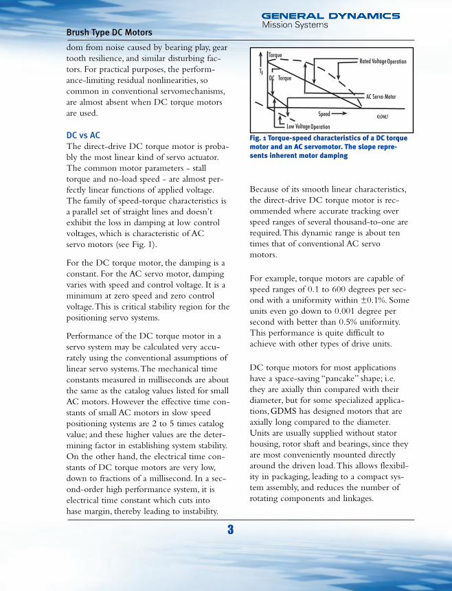
DC vs ACThe direct-drive DC torque motor is proba-bly the most linear kind of servo actuator. The common motor parameters - stall torque and no-load speed - are almost per-fectly linear functions of applied voltage.The family of speed-torque characteristics is a parallel set of straight lines and doesn’t exhibit the loss in damping at low control voltages, which is characteristic of AC servo motors (see Fig. 1).
For the DC torque motor, the damping is aconstant. For the AC servo motor, dampingvaries with speed and control voltage. It is aminimum at zero speed and zero controlvoltage.This is critical stability region for thepositioning servo systems.
Performance of the DC torque motor in aservo system may be calculated very accu-rately using the conventional assumptions oflinear servo systems.The mechanical timeconstants measured in milliseconds are aboutthe same as the catalog values listed for smallAC motors. However the effective time con-stants of small AC motors in slow speedpositioning systems are 2 to 5 times catalogvalue; and these higher values are the deter-mining factor in establishing system stability.On the other hand, the electrical time con-stants of DC torque motors are very low,down to fractions of a millisecond. In a sec-ond-order high performance system, it iselectrical time constant which cuts into hase margin, thereby leading to instability.
Low Voltage
Speed
AC Servo Motor
Rated VoltageTorque
DCT
vNLT
Operation
F
Operation
Torque
Fig. 1 Torque-speed characteristics of a DC torque motor and an AC servomotor. The slope repre-sents inherent motor damping
Because of its smooth linear characteristics, the direct-drive DC torque motor is rec-ommended where accurate tracking over speed ranges of several thousand-to-one are required.This dynamic range is about ten times that of conventional AC servo motors.
For example, torque motors are capable of speed ranges of 0.1 to 600 degrees per sec-ond with a uniformity within ±0.1%. Some units even go down to 0.001 degree per second with better than 0.5% uniformity. This performance is quite difficult to achieve with other types of drive units.
DC torque motors for most applications have a space-saving “pancake” shape; i.e. they are axially thin compared with their diameter, but for some specialized applica-tions, GDMS has designed motors that are axially long compared to the diameter. Units are usually supplied without stator housing, rotor shaft and bearings, since they are most conveniently mounted directly around the driven load.This allows flexibil-ity in packaging, leading to a compact sys-tem assembly, and reduces the number of rotating components and linkages.

Motor Operation Theory(See page 14 for performance parameterdefinitions.)
Basic EquationsSince the DC torque motor is a perma-nent-magnet field, armature-excited DCmotor, the basic equations for DC motorscan be used to establish torque motor char-acteristics.
V = E+IR (1)
E = Kbv (2)T = KtI (3)
Where:
V = applied voltage (volts)E = back EMF (volts)I = current (amps)R = DC resistance (ohms)T = torque (oz-in)Kt = torque sensitivity
Kb = back EMF constant
v = speed (rad/sec)
Substitution into Eq (1) leads to the speed-torque characteristic for a given motor:
The first term represents the voltagerequired to overcome the back EMF of themotor at the desired speed and the secondterm represents the voltage required to pro-duce the desired torque.
Torque motors may be wound to operatesuitably at any practical voltage level.Thiscan be accomplished with no change wha-
V = Kbv + (4)TRKt
4
Brush Type DC Motors
soever in performance. In a set of similarunits, power, torque, and time constants areunchanged.The DC resistance and armatureinductance vary as the square of the voltagerating; the current varies inversely with volt-age rating.
The equivalent circuit of the DC torquemotor as shown in Fig. 2.
Power RelationshipsWe can derive some further important rela-tionships from Eq (1):
V = E + IR
by multiplying each term by I to set up apower equation.
VI = EI + I2R (5)
Since the first term represents input powerand the last term represents copper loss, EImust be the mechanical power developed atthe shaft, in watts (including friction andarmature iron loss). Relating EI to devel-oped shaft power gives:
Stall torque (Tp), stall power (Pp), and no-load speed (vNLT) are inter-related parame-ters of DC servo motors. If any two of thethree are defined, the third parameter isautomatically defined. Eq(7) illustrates thisrelationship:
Where vNLT is the theoretical no-load speedwhich does not include the effect of losses.
PP =TP vNLT
(7)141.612
Tv
141.612EI = (6)

5
Brush Type DC Motors
DampingBy manipulating Eq (7), the following equa-tion for servo motor damping (F0) isderived.
Here Vp/vNLT is, of course, the volts perrad/sec of back EMF (the voltage thatwould be developed if the torque motorwere used as a tachometer). R is armatureresistance (ohms) and F0 is the damping inoz-in per rad/sec.The restrictions imposedby Eq (7) and Eq. (8) are fundamental in set-ting up consistent specifications for highperformance torque motors.
If voltage and vNLTare not available, Fo canbe calculated using back EMF constant andtorque sensitivity.
Fo =Kb*Kt
R
F0 =141.612 ( VP )2
(8)R vNLT
Direct-Drive SystemsMotor Transfer FunctionA DC torque motor can be represented bythe following transfer function for simpli-fied servo analysis.This transfer functionignores motor induction, friction and shaft resonances.
To include the effect of motor inductance,the transfer function is modified to includean additional term.
This function assumes that the mechanicaltime constant is much larger than the elec-trical time constant and that friction isnegligible.
High response DC motors occasionallyhave mechanical time constants thatapproach their electrical time constants. Inthis case it is necessary to use the followingtransfer function.
v 1/Kb=V (TmTeS
2+1) (TmTe)S+1
v 1/Kb=V (TmS+1) (TeS+1)
Te = electrical time constant
v 1/Kb=
V TmS+1
v = speedV = voltage inputKb = back EMF constantTm = mechanical time constant
VE= KBv
LR
Fig. 2 Equivalent circuit of the Brush Type DCmotor. Here L/R constitutes the electrical timeconstant. The component L, in the circuit, repre-sents armature inductance, and can be minimizedby careful design of the magnetic circuit.
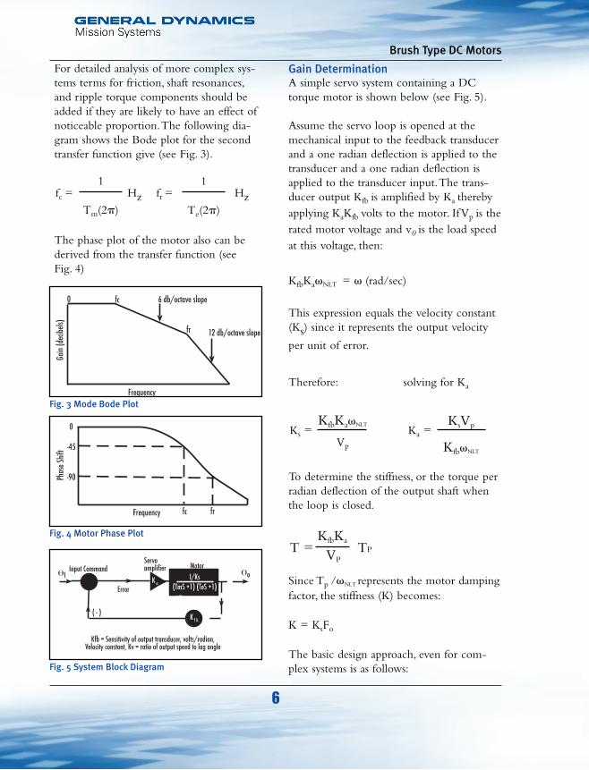
For detailed analysis of more complex sys-tems terms for friction, shaft resonances,and ripple torque components should beadded if they are likely to have an effect ofnoticeable proportion.The following dia-gram shows the Bode plot for the secondtransfer function give (see Fig. 3).
The phase plot of the motor also can bederived from the transfer function (see Fig. 4)
fc = Hz fr = Hz1
Tm(2p)
1
Te(2p)
6
Brush Type DC Motors
Gain DeterminationA simple servo system containing a DCtorque motor is shown below (see Fig. 5).
Assume the servo loop is opened at themechanical input to the feedback transducerand a one radian deflection is applied to thetransducer and a one radian deflection isapplied to the transducer input.The trans-ducer output Kfb is amplified by Ka therebyapplying KaKfb volts to the motor. If Vp is therated motor voltage and v0 is the load speedat this voltage, then:
KfbKavNLT = v (rad/sec)
This expression equals the velocity constant(Ks) since it represents the output velocity
per unit of error.
Therefore: solving for Ka
To determine the stiffness, or the torque perradian deflection of the output shaft whenthe loop is closed.
Since Tp /vNLT represents the motor dampingfactor, the stiffness (K) becomes:
K = KsFo
The basic design approach, even for com-plex systems is as follows:
T =KfbKa
TPVP
Ks = Ka =KfbKavNLT
Vp
KsVp
KfbvNLT
Frequency
12 db/octave slopefr
6 db/octave slopefc0
Gain
(dec
ibels)
Fig. 3 Mode Bode Plot
Fig. 4 Motor Phase Plot
Fig. 5 System Block Diagram
7
Brush Type DC Motors
1. Combine characteristics of motor and loadto arrive at overall figures for inertiaand damping.
2. Using conventional servo system analysisprocedure, draw the open-loop Bode plotrepresenting the desired system velocityconstant, band width, and stability margins.
3. Determine amplifier gain and stiffnessfrom the equations developed above.
4. Check to see that the stiffness is adequateby comparing with the system friction toestablish threshold error.
Amplifier ConsiderationsBecause the torque motor operates on directcurrent, it follows that at least the power stageof the servo amplifier must be a DC amplifier.If the feedback transducer is an AC device,demodulation is required at some point in thesystem.
DC motors may require large currents undertransient conditions and during reversing,therefore careful attention must be paid to thepeak current ratings of the motor and thepower amplifier. Current limiters should beconsidered to overcome this problem.
The power amplifier should have a low out-put impedance to make best use of the inter-nal damping of the motor. Note that dampingtorque is inversely proportional to resistance,which must include the amplifier outputresistance.The output resistance of the ampli-fier under saturated conditions may be a fac-tor in analyzing dynamic response. SCR-typeamplifiers are popular for these applications inspite of their one-cycle transport lag and thetroublesome EMI they generate in the powerlines. Somewhat more complex, but superior
in performance, are pulse-width modulatedamplifiers where power transistor conve-niently switched at one or more kHz, tominimize ripple in the generated torque.The driving amplifier may be modified bycurrent feedback to deliver a current ratherthan a voltage proportional to error.This isequivalent (theoretically) to an infinite out-put impedance. Damping vanishes, and theopen-loop Bode plot falls at 12db/octave atlow frequencies.The electrical time con-stant L/R similarly vanishes, and all damp-ing must be externally supplied.Amplifiercircuits with high output impendance leadto characteristic Type 2 servo system withessentially an infinite velocity constant. It isuseful when available current is limited, andappreciable power output is required at themotor shaft.
Network CompensationThe normal methods of network compen-sation, lead networks, lag networks, lag-leadnetworks, and differentiating networks inthe tachometer feedback loop can be readi-ly applied in direct-drive servo stystems.Since direct current is required for themotor drive, simple DC networks can beused in the amplifier input stages. Circuitsimplification can usually be effected byputting networks in the feedback circuits of DC pre-amplifiers, using well-knowndesign principles.These often lead to moreconvenient sizes for stabilization capacitors.Furthermore, when integrating characteris-tics are required, the saturation of theamplifiers limits the maximum value of theintegrated error, leading to a much reducedovershoot in the response to a large stepinput.This is especially important in veryhigh gain systems where large overshootsand settling lags of several seconds may beintolerable.

Tachometer damping is less convenientthan network compensation because itrequires an additional rotating component,but it does provide the smoothest slow-speed tracking, and avoids saturation effectswhich would disable stabilization networks.
Tachometer StabilizationSince the DC torque motor makes an excel-lent tachometer generator, it is natural to usetachometer damping as a way of increasingthe accuracy of direct-drive servos, especiallythose designed for very low speed operation.
Tachometer damping reduces the systemmechanical time constant by increasing theeffective damping. It also reduces loop gain inthe same proportion.Thus, if it is desired tomultiply band width by decreasing the effec-tive time constant by a factor of 5 for exam-ple, the amplifier gain must be increased by afactor of 25 to maintain the phase marginunchanged (see Fig. 6). Relatively high ampli-fier gains are required in tachometer-dampedloops. However, these lead to proportionallyhigher static stiffness, a very desirable servofeature.
It should be kept in mind that the electricaltime constant has been ignored in this briefanalysis. If a final check indicates significantphase lag from this source at the zero-dbcross-over point on the Bode plot, a correctivereduction in gain must be made.As a matterof fact, the limitation to tachometer feedbackoccurs when the electrical time constant pre-vents achievement of an adequate phase mar-gin.A practical upper limit for cross-over fre-quency would be one half the electrical timeconstant corner frequency.The band width ofa typical tachometer stabilized servo systemwith about 60° open-loop phase margin isabout 40 to 50 cycles per second.
8
Brush Type DC Motors
EMI ConsiderationsThe switching action of the commutator inDC motors usually causes some arcingwhich results in electrical noise.Althoughcareful design can minimize torque motorbrush noise, some arcing noise can get intosensitive control circuits and interfere withproper operation.
Such EMI can be transmitted from a sourceto a sensitive location by direct conductionalong wires; capacitive coupling betweenleads; inductive coupling between wires; anddirect radiation from exposed shafts due toan antenna effect.The first three of thesemethods of transmitting RFI are importantin torque motor applications.
Noise voltages are conducted along themotor supply leads from the power amplifierand transferred to nearby tachometer gener-ator leads by capacitive coupling.Thetachometer generator leads terminate at theinput of a pre-amplifier where only a fewmicrovolts may be enough to interfere withproper system operation.
The simplest remedy is to keep motor leadsseperated from the generator leads. If this isnot enough to reduce the noise or if it isnot feasible to seperate the cable, a shieldedtwisted pair can be used for the tachometerleads.This shield has to be grounded at thepre-amplifier, end only. Sometimes it maybe desirable to use a shielded lead pair forthe motor as well. A common ground forpre-amplifier, amplifier and cables is veryimportant to the elimination of brush noise.Brush noise may be reduced by a filteracross the terminals, as close to the brushassembly as possible.
9
Brush Type DC Motors
Thermal ConsiderationsOn each of the following data pages there isa value for input power at stall torque.Thispower is dissipated as heat in the armaturewinding.The thermal resistance value givenon the motor data pages can be used todetermine the steady state temperatureincrease of the armature above ambient.The thermal resistance is measured with themotor suspended in the air.Air movementand a mounting structure can be used toimprove a motor’s thermal resistance.
The capacity of the motor to handle theload must also take into account the duty-cycle which affects motor heating.A smallmotor with the capacity to drive the loadintermittently may be inadequate whendriving the same load under a more rigorousduty-cycle. Special care must be given to thethermal analysis of rare earth magnet motorssince they can achieve peak torques whichmay cause excessive armature temperaturesunder continuous operation.
Thermal EquationsThe following equations can be used to cal-culate the final temperature of the motorwinding in a given application.The RMStorque must be known so that averagepower dissipation at 25°C can be calculated.P25 = (TRMS/Kt)2 (R25) watts
Where:
P25 = power dissipation @ 258C
R25 = resistance @ 258CKt = torque constantTRMS = RMS torque
If the product of this power and the thermalresistance of the motor is greater than 253then a steady state temperature will never be
reached.A thermal runaway condition willexist.
The final temperature in a nonrunaway sys-tem is:
TF = .9212 P25 x tpr + TAMB (1-.00394 P25 x tpr)
Where:TF = final temperaturetpr = thermal resistanceTAMB = ambient temperature
If the final temperature is greater than theallowable winding temperature, then cool-ing must be provided or a larger motormust be selected.
Standard torque motor armatures are sup-plied with a maximum winding tempera-ture capability of 155ºC. Our design andmanufacturing methods allow availability ofspecial units with temperature capability of220ºC, if required.
Matching Motors to RequirementMatching motors to requirements frequent-ly involves operating a motor below peaktorque ratings. In such cases a simple derat-ing procedure will permit selection of astandard motor.
Significance of Km
The ability of a permanent-magnet DCtorque motor to convert electric powerinput to torque is proportional to the prod-uct of total magnetic flux linking to thewinding from the field and the magneto-

motive forces established by the excitedarmature winding.This ability can be rep-resented by
and is a valid figure of merit to comparetorque motors in their ability to producetorque per unit of input power.This basicmotor constant is included for each motorin the selection chart. If the motor KM is >
the required the motor perform-ance will equal or exceed the demands ofthe application. Note also that Km is closeto the required value, motor size or weightgenerally will be at minimum.
Example ProcedureThe following example illustrates the pro-cedure for using the motor constant Km toselect a motor where the input power isconstrained.
T/ watts
Km = torque/ power input (watts)
10
Brush Type DC Motors
Problem: Develop 50oz-in torque at or nearstall. Maximum amplifier output is 26 voltsat 1 ampere, or 26 watts.
Solution: Using the motor performanceindex (Km) relationship:
Motors with a Km greater than 9.8 can meetthe required torque-to-power condition.Also a torque output can be calculated on aselected motor with 26 watts input by mak-ing the equation equal to torque.
Fig. 7 illustrates torque vs. power deratingfor three motors. Using this information willfacilitate the process of selecting a motorwhen constrained by power supply ratings.Example: A motor is needed to operate atpeak torque of 14 oz-in with a 40 watt
Torque = Km watts = Km 26
Km = T/ watts = 50/ 26 = 9.8
(+)
(-)
(c)
(a)
(b)
0dB
Uncompensated Servomechanism
Tachometer Feedback added phase margin restored
AngularFrequency (Log Scale)
12 dB/oc +5:1 Freq. Range
TachometerFeedback AddedGain Unchanged
Fig.6 Open loop asymptotic attenuation characteristics for a tachometer damped servo system. (a) Original servo with a gain of Ka(b) Tachometer feedback, with a gain of Ka(c) Tachometer feedback, with a gain of 25Ka

11
Brush Type DC Motors
input. Model 1500V-040, while rated at apeak torque of 14 oz-in cannot meet torquerequirements with a 40 watt input. Figure 7,under the torque calculation column, twoother models exceeding the required torquecan be selected.
Motor selection can be made to optimizeweight or configuration. Note the widevariations available in motor diameter, axiallength and weight.
This procedure illustrates the trade-offs nor-mally encountered when derating because ofpower supply limits. In some situations, ther-mal considerations rather than power supplylimits make derating necessary. Installationheat transfer paths and duty-cycles some-times dominate selection criteria.
If a torque motor is derated for powerinput, the damping coefficient
(Fo = Tp/vNLT)
remains constant and therefore for all prac-tical purposes a speed torque characteristicfor a model can be drawn for any DCtorque motor by plotting a straight line between the values for peak torque and no-load speed. (Fig. 7A)
Over-speed OperationAn application sometimes calls for operat-ing a motor above its normal maximumspeed-torque curve.This presents someproblems due to the fact that torquemotors are designed for good commutationat slow speeds and high torques, thereforesome points above the speed-torque curveare points where bad commutation and theresultant decrease in brush life occur. Inorder to avoid this eventuality, it is generallytrue that the motor should not be operatedabove the shaft power output that is repre-sented by the following equation.
ModelPeak Torque
(oz-in)Motor Constant
(Km)Torque @ 40 watts OD
(in)Length
(in)Weight(oz)
1500V-040 14 1.58 9.99 1.500 0.40 1.5
1375V-062 22 2.67 16.89 1.375 0.62 2.5
1500V-062 28 2.91 18.40 1.500 0.62 2.7
Fig. 7 Example of three models using torque vs. power derating @ 40 watts
T=Km watts
Current Limit Level
WNL
Torque
Spee
d
Fig. 7A Family of speed-torque curves.

If more shaft power is desired modificationsmay be possible that will improve commu-tation within acceptable limits.
Typical Motor ApplicationsA common problem is to determine thetorque required to move a load from oneposition to another in a given amount oftime.
The torque required can be calculated:
T = Tf + a (JM + JL)
Where:T = torque needed (oz-in)
a = acceleration (rad/sec2)JM = motor moment of inertia (oz-in/sec2)JL = load moment of inertia (oz-in/sec2)Tf = total system friction torque (oz-in)
If the total angle through which the motormust travel is u radians and the timerequired for the step is t seconds the accel-eration required of the motor is
This equation assumes a triangular veloctiyprofile constant applied torque which willresult in minimum acceleration for the jobas shown in Fig. 8.
a = 4u radt2 sec2
Tp
2Kms dPower = or 1/4 Pp
2
Minimum Power SolutionIf the energy dissipation is of more concernthat minimum acceleration a trapezoidalvelocity profile can be used, as shown in Fig. 9.
One third of the time is used for accelera-tion; the speed is held constant for one thirdof the time and the last third is used fordeceleration. In this case there is a 15% saving in dissipated energy, but the accelera-tion required is:
Voltage and Current RequirementsUsing the motor winding constants the volt-age and current required may now be calcu-lated.
a = 4.5u radt2 sec2
12
Brush Type DC Motors
Constant TorqueAcceleration
Constant Torque*Deceleration
*Resulting fromconstant currentapplied to motor.
Spee
d
00
t/2 t
Fig. 8 Drive motor velocity profile for minimumrequired acceleration in a point-to-point step.
Fig. 9 Drive motor velocity profile for minimumenergy dissipation in a point-to-point step.

peak torque.An amplifier with a currentlimit is a requirement for this type of opera-tion. It should be noted that operation abovethe speed-torque curve decreases motorbrush life.
Motion ConversionIn many applications it is necessary to cou-ple the motor to the load through a motionconverting system, such as gear train, beltand pulley, rack and pinion or lead screw. Ifit is necessary to minimize the energy con-sumed by the system the coupling ratio mustbe optimized. It can be shown that the opti-mum coupling ratio is the ratio whichmatches the reflected load inertia to themotor inertia.The optimum ratio, N, isfound by the following equation:
This equation assumes that the system fric-tion losses at the motor shaft are negligible.For other types of couplings the inertiamatching techniques also minimizes energyconsumption. For example in the lead screwsystem:
whereP = lead screw pitch (turns/in)m = weight of load (oz)JM = motor moment of inertia (oz-in/sec2)g = 386 in/sec2
P =1
2pmJM
N =JL
gJM
for triangular velocity profile
for trapezoidal velocity profile where
KT= torque sensitivity in oz-in/amp
Kb = back EMF in volts/rad/sec
R = motor resistance in ohms
a and t are defined previously
An amplifier can now be selected which iscapable of supplying the calculated voltageand current simultaneously. If the windingthat was chosen for the calculations indi-cates a voltage or current that is not avail-able in existing amplifiers, a special amplifi-er or motor winding should be considered.For this task it is important to know thatthe voltage is directly proportional to thetorque sensitivity of the winding and thatthe current is inversely proportional to thetorque sensitivity.
Exceeding Voltage/Speed RatingsWhen the terminal voltage is above thevoltage at peak torque it is necessary to puta current limiter in the circuit so that themotor will not be overheated by over cur-rents.The motor may be run at speedsabove the specified no-load speed as long asthe torque required is below the specified
V = IR + Kbat3
I =
V = IR +
TKT
Kbat2
13
Brush Type DC Motors

mine the mechanical time constant.
(Pp) Power at Peak Torque.This is the inputpower (in watts) required to produce peaktorque at stall and at 25°C winding temp.
(Fo) Damping factor. (Fo = Tp/vNLT ) The
ratio of the stall torque to the no-load speed(oz-in/rad/sec).The value of Fo is governedby the total amount of resistance in thearmature circuit which must include anydriving power amplifier’s output resistance aswell.The damping effect of Fo is usuallyinsufficient for control system stability inmost applications.Added stabilization is pro-vided by tachometer-generator damping orby circuit compenstion.
(TF)Total Breakaway Torque.The friction con-tributed by the motor to the system determinesthe total breakaway torque (in ounces-inches).It is the sum of the brush-commutator friction,plus the magnetic retarding torques such ashysteresis drag and slot effect drag.
(JM) Moment of Inertia.The moment ofinertial of the armature is measured aboutthe torque motor’s axis of rotation.
(vNLT) No-Load Speed.This is the maximumspeed of the motor (in radians per second) atno-load when the voltage that is required toproduce peak torque is applied.
(a) Maximum Theoretical Acceleration.Theacceleration developed by the motor alone,from stand-still, at the moment when maxi-mum voltage is applied is the maximum the-oretical acceleration in radians per second. Itis equal to the ratio Tp/JM.
(tpr) Thermal Resistance.This is the ratio ofwinding temperature rise to average powercontinuously dissipated from the armature.The tpr values are based on the average I2Rloss in an armature suspended in air without
Performance ParametersDefinitionsOn each of the following pages, data on asingle motor model is presented. Electrical,physical, and mechanical data applying toeach model are given.
Definition of the terms used in these datapages are given below.
Motor data:(Tp) Peak Torque.This is the maximumuseful (non continuous) torque (in ounce-inches) that can be obtained at maximumrecommended current input.
(KM) Motor Constant.This is the ability ofa servo motor to convert electic powerinput to torque-a kind of figure of meritthat can be used to compare motors intheir ability to produce torque per unit ofpower input. It is the ratio of torque to thesquare-root of the power input
( ).
(Te) Electric Time Constant.
( ) The ratio of armature induc-tance to its resistance is the electrical timeconstant of a torque motor (in seconds).
(Tm) Mechanical Time Constant.
( )The ratio of the motor
moment of inertia to the damping factorwith a zero-impedance power source givesthe mechanical time constant of the motor.In direct-drive systems, load inertia anddamping factor have to be added to themotor inertia and damping factor to deter-
TM =R * JM
Kt * Kb
Te = LR
T/ power input (watts)
14
Brush Type DC Motors

heat sink or forced air cooling. In normalapplications the actual value can be 1/2 to1/3 of the listed tpr because the armaturemay be mounted on a shaft with good heatconductivity.(fR) Ripple Frequency.The number of rip-ple cycles in one revolution of the armatureis the ripple frequency (in cycles per revo-lution).A higher frequency componentcaused by the brush phasing also is present,but the fundamental frequency is deter-mined by the number of commutator bars.
(TR) Ripple Torque.A small change intorque with armature position is caused bythe switching action of the commutator.The armature rotates through a small anglebefore its field is returned to its originalposition through commutation.This varia-tion is known as ripple torque and is usual-ly expressed in percent of torque level.
(WT) Weight.Weight of the servo motor isthe sum of the weights of the armature, thefield, and the brush assembly. It does notinclude the weight of the mounting hard-ware.
(R) DC Resistance.This is the DC resist-ance (in ohms) measured at 25°C betweenthe motor terminals. It is the sum of thewinding and brush resistances.This resist-ance is usually measured at 1/3 to 1/5 ofpeak current.
(Vp)Voltage at Peak Torque.This is thevoltage required to produce peak torque(Tp) where the motor is at standstill andthe winding temperature is 25°C.
(Ip) Current at Peak Torque.This is the cur-rent required to obtain peak torque (Tp)from the motor. It is given in amperes.
(KT) Torque sensitivity.This is in torque out-put of the motor per ampere of motor inputcurrent. It is given in ounce-inches perampere.(Kb) Back EMF.This is the voltage generatedby the armature as it rotates in the perma-nent magnetic field and is proportionaldirectly to the speed. It is numerically equalto the torque sensitivity (KT) multiplied by aconstant. It is given in volts/rad/sec.
(LM) Inductance.This is the inductance ofthe motor armature as measured at themotor terminals. It is given in millihenries,measured at 1kHz.
(P) Power Rate.The ratio of peak torquesquared to inertia which is useful in applica-tions where the acceleration of a loadthrough a gear train is the prime considera-tion.An initial motor selection is madewhich has a power rate of at least 4 timesthe product of the load inertia and the loadacceleration required.A gear ratio is thenchosen which will match the motor andload inertia.
15
Brush Type DC Motors

16
Brush Type DC Motors
GDMS produces this 2-axis gimbal that can be used in a variety of applications. The gimbal consists of two brush type motors, a brushless motors, two resolvers, a slip ring assembly and the associated structural components and the electronics.
GDMS DC torque motors are designed using premi-um materials that offer unique space and weight savings while generating maximum power output. Space-rated versions of most motors are available.
GDMS motors incorporate rare earth magnets with outer diameters ranging from 0.5” to 48” and pro-vide peak torques up to 1,650 ft-lbs.

17
Brush Type DC Motors
Brush Mounting Screws
Clamp Screws *
Field Mounting Screws *
Clamp Assemblly *
Commutator
Armature
Mylar Strip / Shim
Field Assembly
* Customer Supplied (for concept only)
Torque Motor AssemblyComponent Parts

DefinitionsArmature - The element containing thewindings and commutator.
Commutator - A conductive segmentedcopper ring on the armature. Allows trans-fer of electrical power to the windings fromthe stationary brush assembly.
Field - The stationary element containingpermanent magnets.
Brush Assembly - The stationary insu-laating ring supporting spring loaded elec-trical contacts (brushes) which slide on thecommutator to transfer the DC power.
OD - The outside diameter of the outer
element.
ID - The inside diameter of the inner ele-ment.
Width - The overall axiall length of themotor.
Mounting - Mounting dimension (shownas MTG DIM on every drawing) is theuser controlled distance from the mountingface of the field to the mounting face ofthe armature. This dimension must bemaintained within the required tolerance toinsure that the brushes align with the com-mutator. Correct mounting is required topreserve the specified perfomance charac-teristics.
AssemblyMounting1. Component PartsThe brush type torque motor consists of
18
Brush Type DC Motors
three major components: A permanentmagnet field, an armature and a brushassembly, are packaged together in serializedsets. The brush ring assembly is protectedby a separate container. Brush installationhardware is included.
2. Field placement and installationPosition the permanent magnet field overthe surface on which it will be mounted.Align the field mounting holes with themounting bolt pattern, push the field intoplace and install the mounting screws at thistime.
3. Protective stripIn order to protect the amature finish andcommutator surface a MYLAR® strip isplaced inside the field at this time. If will beremoved later, so it should be sized so that itextends above the armature for grasping andremoval.
4. Armature installation (Caution: highmagnetic forces may cause damage orinjury.)Slip the armature inside the MYLAR® stripwith the commutator end facing you. Pushthe armature onto the mounting hub. Makesure that it is seated firmly against the shoul-der. Clamp the armature in place. Thecommon method uses a clamp ring andscrews. Other installation methods utilitze athreaded clamp ring, servo clamps orcements for fastening the armature to thehub.
5. Install brush ring assemblyThe brush assembly may be installed byhand. Positon one set of the brushes on theMYLAR® strip, then gently compress theremaining brush springs and slide them ontothe motor.

19
Brush Type DC Motors
6. Assembled motorRemove the MYLAR® strip. Position thelead exits properly (reference line up marks)and align the mounting holes. Fasten thebrush ring to the field using the suppliedhardware. Insure that the brushes are on thecommutator, and that the armature rotatesfreely within the field, the assembly is com-plete.
Drawing and Part NumberExplanation
\1.250 -.001+.000
.620
.400
\.450 MIN.2 PL
.100 MAX.
+.001\.375 -.000
.065
.475
MTG DIM
C'SK 82° x \.150 4 PLAS SHOWN EQ. SP.ON \1.075 B.C.
\.063 THRU
60°
1.
BLACK
RED
2.
(OD)
Brush Assembly(Mounting HardwareSupplied)
(L)
Mounting Holes
Armature
(ID)
Field Assembly,with Rare EarthMagnets
MotorModel
Meaning: 1.250 inches in diameter 0.62 inches in axial length wound as a 7.5 Vwinding
1250 V - 062-075
GDMS complete line of brushless and brush type torque motors and servomotors are sure to include a motor that meets your system’s requirements, or together we can develop a device to meet your specifications.

20
Brush Type DC Motors
Selection Guide
PartNumber:
Peak Torque@ Stall
MotorConstant
No LoadSpeed
Electrical TimeConstant
BreakwayTorque
RotorInertia
ThermalResistance
Physical Dimensions Weight
TP
oz-inPP
wattsKM
oz-in/ W vNL
rad/secTe
millisecTF
oz-inJM
oz-in-sec2uth
°C/wattOD ID L
(in)WT.oz
1125V-036 4 78 0.45 2638 0.12 0.25 .000068 45 1.125 0.250 0.360 0.8
1125V-071 12 95 1.23 1072 0.19 0.45 .00016 30 1.125 0.250 0.710 2
1250V-039 6 59 0.78 1323 0.09 0.45 .00012 41 1.250 0.375 0.390 1.1
1250V-062 12 68 1.45 767.8 0.11 0.55 .00022 32.4 1.250 0.375 0.620 2.1
1375V-039 11 52 1.53 633 0.14 0.60 .00034 35.6 1.375 0.500 0.390 1.4
1375V-062 22 68 2.67 416 0.19 0.75 .00061 27.5 1.375 0.500 0.615 2.5
1500V-040 14 79 1.58 757.6 0.13 0.65 .00044 31.6 1.500 0.625 0.400 1.5
1500V-062 28 93 2.91 447 0.19 0.85 .00077 24 1.500 0.625 0.620 2.7
1500V-085 42 121 3.81 389.5 0.22 1.1 .0011 18 1.500 0.625 0.850 3.9
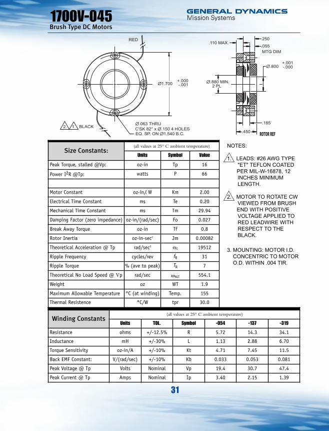
1700V-045 16 66 2.0 554 0.20 0.8 .00082 30 1.700 0.800 0.450 1.9
1700V-090 48 95 4.92 266.6 0.28 1.2 .0019 16 1.700 0.800 0.900 4.8
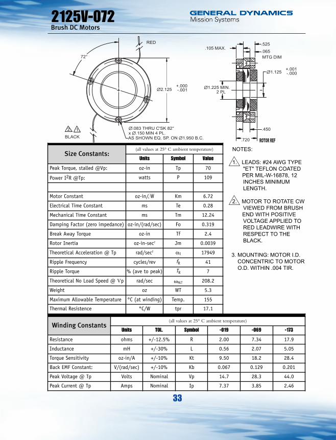
2125V-072 70 109 6.72 208.2 0.28 2.4 .0039 17.1 2.125 1.125 0.720 5.3
2125V-097 105 143 8.77 183.2 0.31 3.0 .0055 13.3 2.125 1.125 0.970 7.6
2375V-096 120 140 10.14 156.8 0.42 3.0 .0075 12.1 2.375 1.250 0.960 9.5
2625V-044 45 51 6.30 153 0.36 1.5 .0059 16.2 2.625 1.375 0.440 4.4
2625V-069 90 69 10.8 103 0.48 2.0 .0103 12.1 2.625 1.375 0.690 7.9
2625V-094 135 70 16.11 69.8 0.56 2.5 .0147 9.7 2.625 1.375 0.940 11.5
2813V-046 55 73 6.44 189 0.34 2.5 .0105 15.1 2.813 1.500 0.460 6
2813V-096 165 85 17.88 69.2 0.62 3.5 .018 9.0 2.813 1.500 0.960 14.5
3000V-053 75 89 7.94 159.6 0.32 2.5 .01 13.5 3.000 1.750 0.530 6.5
3000V-083 150 98 15.13 88 0.39 3.5 .0175 9.7 3.000 1.750 0.830 11.5
3181V-091 200 187 14.61 126.3 0.34 5.0 .022 8.8 3.181 2.000 0.910 12.1
3375V-051 125 142 10.49 153 0.23 4.0 .0155 11.7 3.375 2.125 0.510 7.1
3375V-095 300 177 22.55 79.2 0.38 6.5 .035 7.4 3.375 2.125 0.950 16.3
3625V-054 150 154 12.08 138 0.37 4.5 .0228 10.1 3.625 2.250 0.540 8.5
3625V-084 300 184 22.13 82.5 0.41 6.5 .0396 7.3 3.625 2.250 0.840 15.5
3730V-115 525 321 29.29 82.3 0.39 9.5 .0554 5.7 3.730 2.400 1.150 22.8
4500V-056 325 248 20.64 102.8 0.59 8.0 .0593 6.9 4.500 2.750 0.560 14
4500V-086 650 275 39.19 56.8 0.78 12.0 .1013 5.2 4.500 2.750 0.860 24.6

21
Brush Type DC Motors
Selection Guide
PartNumber:
Peak Torque@ Stall
MotorConstant
No LoadSpeed
Electrical TimeConstant
BreakwayTorque
RotorInertia
ThermalResistance
Physical Dimensions Weight
TP
oz-inPP
wattsKM
oz-in/ W vNL
rad/secTe
millisecTF
oz-inJM
oz-in-sec2uth OD ID L
(in)WT.oz
4500V-146 1300 370 67.56 38.3 1.05 20.0 .1854 3.5 4.500 2.750 1.460 46.5
5125V-058 400 245 25.55 86.7 0.46 12.0 .151 5.7 5.125 3.500 0.580 22
5125V-088 800 248 50.84 41.6 0.76 16.0 .1758 4.3 5.125 3.500 0.880 28
5125V-148 1600 350 85.49 29.5 0.83 24.0 .3198 2.9 5.125 3.500 1.480 52
GDMS designs custom components to meet a customer’s specific requirements. Here are some standard Motors which may satisfy your requirements, should you require a new design or modifications, please contact GDMS.
°C/watt

1. LEADS: #28 AWG TYPE"ET" TEFLON COATED PER MIL-W-16878, 12” MINIMUM LENGTH.
2. MOTOR TO ROTATECW VIEWED FROM BRUSH END WITHPOSITIVE VOLTAGE
NOTES:
APPLIED TO REDLEADWIRE WITHRESPECT TO THEBLACK.
C'SK 82° x \.150 2 HOLESEQ. SP. ON \.938 B.C.
\.063 THRU
\1.125 -.001+.000
1.
.360
.125
BLACK
\.320 MIN.2 PL
.125 MAX.
+.001\.250 -.000
.065
.200
MTG DIM2.
RED
22
Size Constants:(all values at 25° C ambient temperature)
Units Symbol Value
Peak Torque, stalled @Vp: oz-in Tp 4
Power I2R @Tp: watts P 78
Motor Constant oz-in/ W Km 0.45
Electrical Time Constant ms Te 0.12
Mechanical Time Constant ms Tm 47.02
Damping Factor (zero impedance) oz-in/(rad/sec) Fo 0.001
Break Away Torque oz-in Tf 0.25
Rotor Inertia oz-in-sec2 Jm 0.000068
Theoretical Acceleration @ Tp rad/sec2 at 58824
Ripple Frequency cycles/rev fR 13
Ripple Torque % (ave to peak) TR 10
Theoretical No Load Speed @ Vp rad/sec vNLT 2638
Weight oz WT 0.8
Maximum Allowable Temperature °C (at winding) Temp. 155
Thermal Resistence °C/W tpr 45.0
Winding Constants(all values at 25° C ambient temperature)
Units TOL. Symbol -011 -042 -098
Resistance ohms +/-12.5% R 1.27 4.68 10.9
Inductance mH +/-30% L 0.15 0.57 1.92
Torque Sensitivity oz-in/A +/-10% Kt 0.51 0.98 1.5
Back EMF Constant: V/(rad/sec) +/-10% Kb 0.004 0.007 0.011
Peak Voltage @ Tp Volts Nominal Vp 10.0 19.1 29.1
Peak Current @ Tp Amps Nominal Ip 7.84 4.08 2.67
1125V-036Brush Type DC Motors
!W
NOTES:
1. LEADS: #28 AWGTYPE "ET" TEFLON COATED PER MIL-W-16878, 12” MINIMUM LENGTH.
2. MOTOR TO ROTATE CW VIEWED FROM BRUSH END WITH POSITIVE VOLTAGEAPPLIED TO REDLEADWIRE WITHRESPECT TO THE BLACK.
3. MOUNTING: MOTOR I.D.CONCENTRIC TO MOTORO.D. WITHIN .004 TIR.
ROTOR REF

23
1125V-071Brush Type DC Motors
Size Constants:(all values at 25° C ambient temperature)
Units Symbol Value
Peak Torque, stalled @Vp: oz-in Tp 12
Power I2R @Tp: watts P 95
Motor Constant oz-in/ W Km 1.23
Electrical Time Constant ms Te 0.19
Mechanical Time Constant ms Tm 15.00
Damping Factor (zero impedance) oz-in/(rad/sec) Fo 0.011
Break Away Torque oz-in Tf 0.45
Rotor Inertia oz-in-sec2 Jm 0.00016
Theoretical Acceleration @ Tp rad/sec2 at 75000
Ripple Frequency cycles/rev fR 13
Ripple Torque % (ave to peak) TR 10
Theoretical No Load Speed @ Vp rad/sec vNLT 1072.4
Weight oz WT 2.0
Maximum Allowable Temperature °C (at winding) Temp. 155
Thermal Resistence °C/W tpr 30.0
C'SK 82° x \.150 2 HOLESEQ. SP. ON \.938 B.C.
\.063 THRU
\1.125 -.001+.000
.710
.475
\.320 MIN.2 PL
.125 MAX.
+.001\.250 -.000
.065
.550
MTG DIM
1. LEADS: #26 AWGTYPE "ET" TEFLONCOATED PERMIL-W-16878, 12”MINIMUM LENGTH.
2. MOTOR TO ROTATECW VIEWED FROMBRUSH END WITHPOSITIVE VOLTAGE
NOTES:
1.BLACK
2.
RED
Winding Constants(all values at 25° C ambient temperature)
Units TOL. Symbol -011 -041 -100
Resistance ohms +/-12.5% R 1.26 4.72 11.4
Inductance mH +/-30% L 0.24 0.88 2.12
Torque Sensitivity oz-in/A +/-10% Kt 1.38 2.67 4.15
Back EMF Constant: V(rad/sec) +/-10% Kb 0.010 0.019 0.029
Peak Voltage @ Tp Volts Nominal Vp 11.0 21.2 32.9
Peak Current @ Tp Amps Nominal Ip 8.70 4.49 2.89
!W
NOTES:
1. LEADS: #26 AWGTYPE "ET" TEFLONCOATED PERMIL-W-16878, 12” MINIMUM LENGTH.
2. MOTOR TO ROTATECW VIEWED FROMBRUSH END WITH POSITIVE VOLTAGEAPPLIED TO RED LEADWIRE WITH RESPECT TO THE BLACK.
3. MOUNTING: MOTOR I.D.CONCENTRIC TO MOTORO.D. WITHIN .004 TIR.
ROTOR REF

24
1250V-039Brush Type DC Motors
Size Constants:(all values at 25° C ambient temperature)
Units Symbol Value
Peak Torque, stalled @Vp: oz-in Tp 6
Power I2R @Tp: watts P 59
Motor Constant oz-in/ W Km 0.78
Electrical Time Constant ms Te 0.09
Mechanical Time Constant ms Tm 27.85
Damping Factor (zero impedance) oz-in/(rad/sec) Fo 0.004
Break Away Torque oz-in Tf 0.45
Rotor Inertia oz-in-sec2 Jm 0.00012
Theoretical Acceleration @ Tp rad/sec2 at 50000
Ripple Frequency cycles/rev fR 23
Ripple Torque % (ave to peak) TR 7
Theoretical No Load Speed @ Vp rad/sec vNLT 1322.9
Weight oz WT 1.1
Maximum Allowable Temperature °C (at winding) Temp. 155
Thermal Resistence °C/W tpr 41.0
\1.250 -.001+.000
.390
.175
\.450 MIN.2 PL
.100 MAX.
+.001\.375 -.000
.065
.250
MTG DIM
1.
BLACK
RED
C'SK 82° x \.150 4 PLAS SHOWN EQ. SP.ON \1.075 B.C.
\.063 THRU
60°
2.
Winding Constants(all values at 25° C ambient temperature)
Units TOL. Symbol -022 -079 -213
Resistance ohms +/-12.5% R 2.36 8.40 21.7
Inductance mH +/-30% L 0.21 0.74 1.93
Torque Sensitivity oz-in/A +/-10% Kt 1.20 2.26 3.64
Back EMF Constant: V/(rad/sec) +/-10% Kb 0.008 0.016 0.026
Peak Voltage @ Tp Volts Nominal Vp 11.8 22.3 35.8
Peak Current @ Tp Amps Nominal Ip 5.00 2.65 1.65
!W
NOTES:
1. LEADS: #26 AWG TYPE"ET" TEFLONCOATED PER MIL-W-16878, 12 INCHESMINIMUM LENGTH.
2. MOTOR TO ROTATE CWVIEWED FROM BRUSHEND WITH POSITIVEVOLTAGE APPLIED TORED LEADWIRE WITHRESPECT TO THEBLACK.
3. MOUNTING: MOTOR I.D.CONCENTRIC TO MOTORO.D. WITHIN .004 TIR.
ROTOR REF

25
1250V-062Brush DC Motors
Size Constants:(all values at 25° C ambient temperature)
Units Symbol Value
Peak Torque, stalled @Vp: oz-in Tp 12
Power I2R @Tp: watts P 68
Motor Constant oz-in/ W Km 1.45
Electrical Time Constant ms Te 0.11
Mechanical Time Constant ms Tm 14.78
Damping Factor (zero impedance) oz-in/(rad/sec) Fo 0.015
Break Away Torque oz-in Tf 0.55
Rotor Inertia oz-in-sec2 Jm 0.00022
Theoretical Acceleration @ Tp rad/sec2 at 54545
Ripple Frequency cycles/rev fR 23
Ripple Torque %(ave to peak) TR 7
Theoretical No Load Speed @ Vp rad/sec vNLT 767.8
Weight oz WT 2.1
Maximum Allowable Temperature °C (at winding) Temp. 155
Thermal Resistence °C/W tpr 32.4
\1.250 -.001+.000
.620
.400
\.450 MIN.2 PL
.100 MAX.
+.001\.375 -.000
.065
.475
MTG DIM
C'SK 82° x \.150 4 PLAS SHOWN EQ. SP.ON \1.075 B.C.
\.063 THRU
60°
1.
BLACK
RED
2.
Winding Constants(all values at 25° C ambient temperature)
Units TOL. Symbol -019 -075 -176
Resistance ohms +/-12.5% R 1.86 7.80 18.3
Inductance mH +/-30% L 0.20 0.84 1.98
Torque Sensitivity oz-in/A +/-10% Kt 1.98 4.05 6.21
Back EMF Constant: V/(rad/sec) +/-10% Kb 0.014 0.029 0.044
Peak Voltage @ Tp Volts Nominal Vp 11.3 23.1 35.3
Peak Current @ Tp Amps Nominal Ip 6.06 2.96 1.93
!W
NOTES:
1. LEADS: #26 AWG TYPE"ET" TEFLON COATEDPER MIL-W-16878, 12INCHES MINIMUMLENGTH.
2. MOTOR TO ROTATE CWVIEWED FROM BRUSHEND WITH POSITIVEVOLTAGE APPLIED TORED LEADWIRE WITHRESPECT TO THEBLACK.
3. MOUNTING: MOTOR I.D.CONCENTRIC TO MOTORO.D. WITHIN .004 TIR.
ROTOR REF

26
1375V-039Brush Type DC Motors
Size Constants:(all values at 25° C ambient temperature)
Units Symbol Value
Peak Torque, stalled @Vp: oz-in Tp 11
Power I2R @Tp: watts P 52
Motor Constant oz-in/ W Km 1.53
Electrical Time Constant ms Te 0.14
Mechanical Time Constant ms Tm 20.65
Damping Factor (zero impedance) oz-in/(rad/sec) Fo 0.016
Break Away Torque oz-in Tf 0.60
Rotor Inertia oz-in-sec2 Jm 0.00034
Theoretical Acceleration @ Tp rad/sec2 at 32353
Ripple Frequency cycles/rev fR 29
Ripple Torque % (ave to peak) TR 7
Theoretical No Load Speed @ Vp rad/sec vNLT 632.9
Weight oz WT 1.4
Maximum Allowable Temperature °C (at winding) Temp. 155
Thermal Resistence °C/W tpr. 35.6
\1.375 -.001+.000
.390
.175
\.580 MIN.2 PL
.100 MAX.
+.001\.500 -.000
.065
.250
MTG DIM
C'SK 82° x \.125 4 HOLESEQ. SP. ON \1.245 B.C.
\.063 THRU2.
RED
1. BLACK
Winding Constants(all values at 25° C ambient temperature)
UNITS TOL. Symbol -046 -110 -264
Resistance ohms +/-12.5% R 4.90 11.8 28.4
Inductance mH +/-30% L 0.70 1.70 3.93
Torque Sensitivity oz-in/A +/-10% Kt 3.38 5.25 8.14
Back EMF Constant: V/(rad/sec) +/-10% Kb 0.024 0.037 0.057
Peak Voltage @ Tp Volts Nominal Vp 15.9 24.8 38.3
Peak Current @ Tp Amps Nominal Ip 3.25 2.10 1.35
!W
NOTES:
1. LEADS: #26 AWG TYPE"ET" TEFLON COATEDPER MIL-W-16878, 12INCHES MINIMUMLENGTH.
2. MOTOR TO ROTATE CWVIEWED FROM BRUSHEND WITH POSITIVEVOLTAGE APPLIED TORED LEADWIRE WITHRESPECT TO THEBLACK.
3. MOUNTING: MOTOR I.D.CONCENTRIC TO MOTORO.D. WITHIN .004 TIR.
ROTOR REF

27
1375V-062Brush Type DC Motors
Size Constants:(all values at 25° C ambient temperature)
Units Symbol Value
Peak Torque, stalled @Vp: oz-in Tp 22
Power I2R @Tp: watts P 68
Motor Constant oz-in/ W Km 2.67
Electrical Time Constant ms Te 0.19
Mechanical Time Constant ms Tm 12.13
Damping Factor (zero impedance) oz-in/(rad/sec) Fo 0.050
Break Away Torque oz-in Tf 0.75
Rotor Inertia oz-in-sec2 Jm 0.00061
Theoretical Acceleration @ Tp rad/sec2 at 36066
Ripple Frequency cycles/rev fR 29
Ripple Torque % (ave to peak) TR 7
Theoretical No Load Speed @ Vp rad/sec vNLT 416.0
Weight oz WT 2.5
Maximum Allowable Temperature °C (at winding) Temp. 155
Thermal Resistence °C/W tpr 27.5
\1.375 -.001+.000
.615
.400
\.580 MIN.2 PL
.100 MAX.
+.001\.500 -.000
.065
.475
MTG DIM
C'SK 82° x \.125 4 HOLESEQ. SP. ON \1.245 B.C.
\.063 THRU
2.
RED
1. BLACK
Winding Constants(all values at 25° C ambient temperature)
Units TOL. Symbol -017 -064 -156
Resistance ohms +/-12.5% R 1.81 6.72 16.4
Inductance mH +/-30% L 0.34 1.25 3.10
Torque Sensitivity oz-in/A +/-10% Kt 3.59 6.92 10.8
Back EMF Constant: V/(rad/sec) +/-10% Kb 0.025 0.049 0.076
Peak Voltage @ Tp Volts Nominal Vp 11.1 21.4 33.5
Peak Current @ Tp Amps Nominal Ip 6.13 3.18 2.04
!W
NOTES:
1. LEADS: #26 AWG TYPE"ET" TEFLON COATEDPER MIL-W-16878, 12INCHES MINIMUMLENGTH.
2. MOTOR TO ROTATE CWVIEWED FROM BRUSHEND WITH POSITIVEVOLTAGE APPLIED TORED LEADWIRE WITHRESPECT TO THEBLACK.
3. MOUNTING: MOTOR I.D.CONCENTRIC TO MOTORO.D. WITHIN .004 TIR.
ROTOR REF

28
1500V-040Brush Type DC Motors
Size Constants:(all values at 25° C ambient temperature)
Units Symbol Value
Peak Torque, stalled @Vp: oz-in Tp 14
Power I2R @Tp: watts P 79
Motor Constant oz-in/ W Km 1.58
Electrical Time Constant ms Te 0.13
Mechanical Time Constant ms Tm 25.03
Damping Factor (zero impedance) oz-in/(rad/sec) Fo 0.018
Break Away Torque oz-in Tf 0.65
Rotor Inertia oz-in-sec2 Jm 0.00044
Theoretical Acceleration @ Tp rad/sec2 at 31818
Ripple Frequency cycles/rev fR 29
Ripple Torque %(ave to peak) TR 7
Theoretical No Load Speed @ Vp rad/sec vNLT 757.6
Weight oz WT 1.5
Maximum Allowable Temperature °C(at winding) Temp. 155
Thermal Resistence °C/W tpr 31.6
\1.500 -.001+.000
.400
.175
\.700 MIN.2 PL
.100 MAX.
+.001\.625 -.000
.065
.250
MTG DIM
C'SK 82° x \.125 4 HOLESEQ. SP. ON \1.365 B.C.
\.063 THRU1.BLACK
2.
RED
Winding Constants(all values at 25° C ambient temperature)
Units TOL. Symbol -013 -049 -121
Resistance ohms +/-12.5% R 1.45 5.41 13.7
Inductance mH +/-30% L 0.19 0.70 1.79
Torque Sensitivity oz-in/A +/-10% Kt 1.90 3.67 5.84
Back EMF Constant: V/(rad/sec) +/-10% Kb 0.013 0.026 0.041
Peak Voltage @ Tp Volts Nominal Vp 10.7 20.6 32.9
Peak Current @ Tp Amps Nominal Ip 7.37 3.81 2.40
!W
NOTES:
1. LEADS: #26 AWG TYPE"ET" TEFLON COATEDPER MIL-W-16878, 12INCHES MINIMUMLENGTH.
2. MOTOR TO ROTATE CWVIEWED FROM BRUSHEND WITH POSITIVEVOLTAGE APPLIED TORED LEADWIRE WITHRESPECT TO THEBLACK.
3. MOUNTING: MOTOR I.D.CONCENTRIC TO MOTORO.D. WITHIN .004 TIR.
ROTOR REF

29
1500V-062Brush Type DC Motors
Size Constants:(all values at 25° C ambient temperature)
Units Symbol Value
Peak Torque, stalled @Vp: oz-in Tp 28
Power I2R @Tp: watts P 93
Motor Constant oz-in/ W Km 2.91
Electrical Time Constant ms Te 0.19
Mechanical Time Constant ms tm 12.9
Damping Factor (zero impedance) oz-in/(rad/sec) Fo 0.060
Break Away Torque oz-in Tf 0.85
Rotor Inertia oz-in-sec2 Jm 0.00077
Theoretical Acceleration @ Tp rad/sec2 at 36364
Ripple Frequency cycles/rev fR 29
Ripple Torque % (ave to peak) TR 7
Theoretical No Load Speed @ Vp rad/sec vNLT 447.1
Weight oz WT 2.7
Maximum Allowable Temperature °C (at winding) Temp. 155
Thermal Resistence °C/W tpr 24.0
\1.500 -.001+.000
.620
.400
\.700 MIN.2 PL
.100 MAX.
+.001\.625 -.000
.065
.475
MTG DIM
C'SK 82° x \.125 4 HOLESEQ. SP. ON \1.365 B.C.
\.063 THRU1. BLACK2.
RED
Winding Constants(all values at 25° C ambient temperature)
Units TOL. Symbol -012 -043 -105
Resistance ohms +/-12.5% R 1.25 4.77 11.3
Inductance mH +/-30% L 0.24 0.92 2.17
Torque Sensitivity oz-in/A +/-10% Kt 3.25 6.35 9.77
Back EMF Constant: V/(rad/sec) +/-10% Kb 0.023 0.045 0.069
Peak Voltage @ Tp Volts Nominal Vp 10.8 21.0 32.4
Peak Current @ Tp Amps Nominal Ip 8.59 4.41 2.87
!W
NOTES:
1. LEADS: #26 AWG TYPE"ET" TEFLON COATEDPER MIL-W-16878, 12INCHES MINIMUMLENGTH.
2. MOTOR TO ROTATE CWVIEWED FROM BRUSHEND WITH POSITIVEVOLTAGE APPLIED TORED LEADWIRE WITHRESPECT TO THEBLACK.
3. MOUNTING: MOTOR I.D.CONCENTRIC TO MOTORO.D. WITHIN .004 TIR.
ROTOR REF

30
Size Constants:(all values at 25° C ambient temperature)
Units Symbol Value
Peak Torque, stalled @Vp: oz-in Tp 42
Power I2R @Tp: watts P 121
Motor Constant oz-in/ W Km 3.81
Electrical Time Constant ms Te 0.22
Mechanical Time Constant ms tm 10.71
Damping Factor (zero impedance) oz-in/(rad/sec) Fo 0.103
Break Away Torque oz-in Tf 1.1
Rotor Inertia oz-in-sec2 Jm 0.0011
Theoretical Acceleration @ Tp rad/sec2 at 38182
Ripple Frequency cycles/rev fR 29
Ripple Torque % (ave to peak) TR 7
Theoretical No Load Speed @ Vp rad/sec vNLT 389.5
Weight oz WT 3.9
Maximum Allowable Temperature °C (at winding) Temp. 155
Thermal Resistence °C/W tpr 18.0
\1.500 -.001+.000
.850
.625
\.700 MIN.2 PL
.100 MAX.
+.001\.625 -.000
.065
.700
MTG DIM
C'SK 82° x \.125 4 HOLESEQ. SP. ON \1.365 B.C.
\.063 THRU1. BLACK2.
RED
1500V-085Brush Type DC Motors
Winding Constants(all values at 25° C ambient temperature)
Units TOL. Symbol -015 -034 -084
Resistance ohms +/-12.5% R 1.63 3.88 9.62
Inductance mH +/-30% L 0.36 0.85 2.14
Torque Sensitivity oz-in/A +/-10% Kt 4.87 7.51 11.83
Back EMF Constant: V/(rad/sec) +/-10% Kb 0.034 0.053 0.084
Peak Voltage @ Tp Volts Nominal Vp 14.1 21.7 34.2
Peak Current @ Tp Amps Nominal Ip 8.62 5.59 3.55
!W
NOTES:
1. LEADS: #26 AWG TYPE"ET" TEFLON COATEDPER MIL-W-16878, 12INCHES MINIMUMLENGTH.
2. MOTOR TO ROTATE CWVIEWED FROM BRUSHEND WITH POSITIVEVOLTAGE APPLIED TORED LEADWIRE WITHRESPECT TO THEBLACK.
3. MOUNTING: MOTOR I.D.CONCENTRIC TO MOTORO.D. WITHIN .004 TIR.
ROTOR REF
31
Size Constants:(all values at 25° C ambient temperature)
Units Symbol Value
Peak Torque, stalled @Vp: oz-in Tp 16
Power I2R @Tp: watts P 66
Motor Constant oz-in/ W Km 2.00
Electrical Time Constant ms Te 0.20
Mechanical Time Constant ms Tm 29.94
Damping Factor (zero impedance) oz-in/(rad/sec) Fo 0.027
Break Away Torque oz-in Tf 0.8
Rotor Inertia oz-in-sec2 Jm 0.00082
Theoretical Acceleration @ Tp rad/sec2 at 19512
Ripple Frequency cycles/rev fR 31
Ripple Torque % (ave to peak) TR 7
Theoretical No Load Speed @ Vp rad/sec vNLT 554.1
Weight oz WT 1.9
Maximum Allowable Temperature °C (at winding) Temp. 155
Thermal Resistence °C/W tpr 30.0
\1.700 -.001+.000
.450
.185
\.880 MIN.2 PL
.110 MAX.
+.001\.800 -.000
.055
.250
MTG DIM
C'SK 82° x \.150 4 HOLESEQ. SP. ON \1.540 B.C.
\.063 THRU1. BLACK2.
RED
1700V-045Brush Type DC Motors
Winding Constants(all values at 25° C ambient temperature)
Units TOL. Symbol -054 -137 -319
Resistance ohms +/-12.5% R 5.72 14.3 34.1
Inductance mH +/-30% L 1.13 2.88 6.70
Torque Sensitivity oz-in/A +/-10% Kt 4.71 7.45 11.5
Back EMF Constant: V/(rad/sec) +/-10% Kb 0.033 0.053 0.081
Peak Voltage @ Tp Volts Nominal Vp 19.4 30.7 47.4
Peak Current @ Tp Amps Nominal Ip 3.40 2.15 1.39
!W
NOTES:
1. LEADS: #26 AWG TYPE"ET" TEFLON COATEDPER MIL-W-16878, 12INCHES MINIMUMLENGTH.
2. MOTOR TO ROTATE CWVIEWED FROM BRUSHEND WITH POSITIVEVOLTAGE APPLIED TORED LEADWIRE WITHRESPECT TO THEBLACK.
3. MOUNTING: MOTOR I.D.CONCENTRIC TO MOTORO.D. WITHIN .004 TIR.
ROTOR REF

32
Size Constants:(all values at 25° C ambient temperature)
Units Symbol Value
Peak Torque, stalled @Vp: oz-in Tp 48
Power I2R @Tp: watts P 95
Motor Constant oz-in/ W Km 4.92
Electrical Time Constant ms Te 0.28
Mechanical Time Constant ms Tm 11.12
Damping Factor (zero impedance) oz-in/(rad/sec) Fo 0.171
Break Away Torque oz-in Tf 1.2
Rotor Inertia oz-in-sec2 Jm 0.0019
Theoretical Acceleration @ Tp rad/sec2 at 25263
Ripple Frequency cycles/rev fR 31
Ripple Torque % (ave to peak) TR 7
Theoretical No Load Speed @ Vp rad/sec vNLT 266.6
Weight oz WT 4.8
Maximum Allowable Temperature °C (at winding) Temp. 155
Thermal Resistence °C/W tpr 16.0
\1.700 -.001+.000
.900
.635
\.880 MIN.2 PL
.110 MAX.
+.001\.800 -.000
.055
.700
MTG DIM
C'SK 82° x \.150 4 HOLESEQ. SP. ON \1.540 B.C.
\.063 THRU1.BLACK2.
RED
1700V-090Brush DC Motors
Winding Constants(all values at 25° C ambient temperature)
Units TOL. Symbol -038 -090 -229
Resistance ohms +/-12.5% R 4.00 9.54 23.8
Inductance mH +/-30% L 1.13 2.67 6.71
Torque Sensitivity oz-in/A +/-10% Kt 9.84 15.2 24.0
Back EMF Constant: V/(rad/sec) +/-10% Kb 0.069 0.107 0.169
Peak Voltage @ Tp Volts Nominal Vp 19.5 30.1 47.6
Peak Current @ Tp Amps Nominal Ip 4.88 3.16 2.00
!W
NOTES:
1. LEADS: #26 AWG TYPE"ET" TEFLON COATEDPER MIL-W-16878, 12INCHES MINIMUMLENGTH.
2. MOTOR TO ROTATE CWVIEWED FROM BRUSHEND WITH POSITIVEVOLTAGE APPLIED TORED LEADWIRE WITHRESPECT TO THEBLACK.
3. MOUNTING: MOTOR I.D.CONCENTRIC TO MOTORO.D. WITHIN .004 TIR.
ROTOR REF
33
Size Constants:(all values at 25° C ambient temperature)
Units Symbol Value
Peak Torque, stalled @Vp: oz-in Tp 70
Power I2R @Tp: watts P 109
Motor Constant oz-in/ W Km 6.72
Electrical Time Constant ms Te 0.28
Mechanical Time Constant ms Tm 12.24
Damping Factor (zero impedance) oz-in/(rad/sec) Fo 0.319
Break Away Torque oz-in Tf 2.4
Rotor Inertia oz-in-sec2 Jm 0.0039
Theoretical Acceleration @ Tp rad/sec2 at 17949
Ripple Frequency cycles/rev fR 41
Ripple Torque % (ave to peak) TR 7
Theoretical No Load Speed @ Vp rad/sec vNLT 208.2
Weight oz WT 5.3
Maximum Allowable Temperature °C (at winding) Temp. 155
Thermal Resistence °C/W tpr 17.1
\2.125 -.001+.000
.720
.450
\1.225 MIN.2 PL
.105 MAX.
+.001\1.125 -.000
.065
.525
MTG DIM
1.BLACK
RED
72°
x \.150 MIN 4 PL.AS SHOWN EQ. SP. ON \1.950 B.C.
\.083 THRU C'SK 82°2.
2125V-072Brush DC Motors
Winding Constants(all values at 25° C ambient temperature)
Units TOL. Symbol -019 -069 -173
Resistance ohms +/-12.5% R 2.00 7.34 17.9
Inductance mH +/-30% L 0.56 2.07 5.05
Torque Sensitivity oz-in/A +/-10% Kt 9.50 18.2 28.4
Back EMF Constant: V/(rad/sec) +/-10% Kb 0.067 0.129 0.201
Peak Voltage @ Tp Volts Nominal Vp 14.7 28.3 44.0
Peak Current @ Tp Amps Nominal Ip 7.37 3.85 2.46
!W
NOTES:
1. LEADS: #24 AWG TYPE"ET" TEFLON COATEDPER MIL-W-16878, 12INCHES MINIMUMLENGTH.
2. MOTOR TO ROTATE CWVIEWED FROM BRUSHEND WITH POSITIVEVOLTAGE APPLIED TORED LEADWIRE WITHRESPECT TO THEBLACK.
3. MOUNTING: MOTOR I.D.CONCENTRIC TO MOTORO.D. WITHIN .004 TIR.
ROTOR REF

34
Size Constants:(all values at 25° C ambient temperature)
Units Symbol Value
Peak Torque, stalled @Vp: oz-in Tp 105
Power I2R @Tp: watts P 143
Motor Constant Km 8.77
Electrical Time Constant ms Te 0.31
Mechanical Time Constant ms Tm 10.13
Damping Factor (zero impedance) oz-in/(rad/sec) Fo 0.543
Break Away Torque oz-in Tf 3.0
Rotor Inertia oz-in-sec2 Jm 0.0055
Theoretical Acceleration @ Tp rad/sec2 at 19091
Ripple Frequency cycles/rev fR 41
Ripple Torque % (ave to peak) TR 7
Theoretical No Load Speed @ Vp rad/sec vNLT 183.2
Weight oz WT 7.6
Maximum Allowable Temperature °C (at winding) Temp. 155
Thermal Resistence °C/W tpr 13.3
\2.125 -.001+.000
.970
.700
\1.225 MIN.2 PL
.105 MAX.
+.001\1.125 -.000
.065
.775
MTG DIM
1.BLACK
RED
72°
\.083 THRU C'SK 82°x \.150 MIN 4 PL.AS SHOWN EQ. SP. ON \1.950 B.C.
2.
2125V-097Brush DC Motors
Winding Constants(all values at 25° C ambient temperature)
Units TOL. Symbol -016 -056 -130
Resistance ohms +/-12.5% R 1.75 6.07 13.4
Inductance mH +/-30% L 0.54 1.89 4.15
Torque Sensitivity oz-in/A +/-10% Kt 11.6 21.6 32.1
Back EMF Constant: V/(rad/sec) +/-10% Kb 0.082 0.153 0.227
Peak Voltage @ Tp Volts Nominal Vp 15.8 29.5 43.8
Peak Current @ Tp Amps Nominal Ip 9.05 4.86 3.27
oz-in/ W!W
NOTES:
1. LEADS: #24 AWG TYPE"ET" TEFLON COATEDPER MIL-W-16878, 12INCHES MINIMUMLENGTH.
2. MOTOR TO ROTATE CWVIEWED FROM BRUSHEND WITH POSITIVEVOLTAGE APPLIED TORED LEADWIRE WITHRESPECT TO THEBLACK.
3. MOUNTING: MOTOR I.D.CONCENTRIC TO MOTORO.D. WITHIN .004 TIR.
ROTOR REF

35
Size Constants:(all values at 25° C ambient temperature)
Units Symbol Value
Peak Torque, stalled @Vp: oz-in Tp 120
Power I2R @Tp: watts P 140
Motor Constant oz-in/ W Km 10.14
Electrical Time Constant ms Te 0.42
Mechanical Time Constant ms Tm 10.33
Damping Factor (zero impedance) oz-in/(rad/sec) Fo 0.726
Break Away Torque oz-in Tf 3.0
Rotor Inertia oz-in-sec2 Jm 0.0075
Theoretical Acceleration @ Tp rad/sec2 at 16000
Ripple Frequency cycles/rev fR 41
Ripple Torque % (ave to peak) TR 7
Theoretical No Load Speed @ Vp rad/sec vNLT 156.8
Weight oz WT 9.5
Maximum Allowable Temperature °C (at winding) Temp. 155
Thermal Resistence °C/W tpr 12.1
\2.375 -.001+.000
.960
.700
\1.350 MIN.2 PL
.105 MAX.
+.001\1.250 -.000
.065
.775
MTG DIM
1.BLACK
RED
72°
x \.150 MIN 4 PL.AS SHOWN EQ. SP. ON \2.200 B.C.
\.083 THRU C'SK 82°2.
2375V-096Brush DC Motors
Winding Constants(all values at 25° C ambient temperature)
Units TOL. Symbol -018 -065 -149
Resistance ohms +/-12.5% R 1.88 7.09 16.1
Inductance mH +/-30% L 0.79 2.98 6.76
Torque Sensitivity oz-in/A +/-10% Kt 13.9 27.0 40.7
Back EMF Constant: V/(rad/sec) +/-10% Kb 0.098 0.191 0.287
Peak Voltage @ Tp Volts Nominal Vp 16.2 31.5 47.5
Peak Current @ Tp Amps Nominal Ip 8.63 4.44 2.95
!W
NOTES:
1. LEADS: #24 AWG TYPE"ET" TEFLON COATEDPER MIL-W-16878, 12INCHES MINIMUMLENGTH.
2. MOTOR TO ROTATE CWVIEWED FROM BRUSHEND WITH POSITIVEVOLTAGE APPLIED TORED LEADWIRE WITHRESPECT TO THEBLACK.
3. MOUNTING: MOTOR I.D.CONCENTRIC TO MOTORO.D. WITHIN .004 TIR.
ROTOR REF

36
Size Constants:(all values at 25° C ambient temperature)
Units Symbol Value
Peak Torque, stalled @Vp: oz-in Tp 45
Power I2R @Tp: watts P 51
Motor Constant oz-in/ W Km 6.30
Electrical Time Constant ms Te 0.36
Mechanical Time Constant ms Tm 21.05
Damping Factor (zero impedance) oz-in/(rad/sec) Fo 0.280
Break Away Torque oz-in Tf 1.5
Rotor Inertia oz-in-sec2 Jm 0.0059
Theoretical Acceleration @ Tp rad/sec2 at 7627
Ripple Frequency cycles/rev fR 49
Ripple Torque % (ave to peak) TR 7
Theoretical No Load Speed @ Vp rad/sec vNLT 152.9
Weight oz WT 4.4
Maximum Allowable Temperature °C (at winding) Temp. 155
Thermal Resistence °C/W tpr 16.2
\2.625 -.001+.000
.440
.200
\1.475 MIN.2 PL
.100 MAX.
+.001\1.375 -.000
.065
.275
MTG DIM
C'SK 82° x \.150 4 HOLESEQ. SP. ON \2.460 B.C.
\.083 THRU1.BLACK
2.
RED
2625V-044Brush DC Motors
WindingConstants
(all values at 25° C ambient temperature)
Units TOL. Symbol -039 -090 -141 -226
Resistance omhs +/-12.5% R 4.39 10.1 15.5 24.7
Inductance mH +/-30% L 1.58 3.64 5.58 8.90
Torque Sensitivity oz-in/A +/-10% Kt 13.2 20.0 24.8 31.3
Back EMF Constant: V/(rad/sec) +/-10% Kb 0.093 0.141 0.175 0.221
Peak Voltage @ Tp Volts Nominal Vp 15.0 22.7 28.1 35.6
Peak Current @ Tp Amps Nominal Ip 3.41 2.25 1.81 1.44
!W
NOTES:
1. LEADS: #26 AWG TYPE"ET" TEFLON COATEDPER MIL-W-16878, 12INCHES MINIMUMLENGTH.
2. MOTOR TO ROTATE CWVIEWED FROM BRUSHEND WITH POSITIVEVOLTAGE APPLIED TORED LEADWIRE WITHRESPECT TO THEBLACK.
3. MOUNTING: MOTOR I.D.CONCENTRIC TO MOTORO.D. WITHIN .004 TIR.
ROTOR REF

37
Size Constants:(all values at 25° C ambient temperature)
Units Symbol Value
Peak Torque, stalled @Vp: oz-in Tp 90
Power I2R @Tp: watts P 69
Motor Constant oz-in/ W Km 10.8
Electrical Time Constant ms Te 0.48
Mechanical Time Constant ms Tm 12.4
Damping Factor (zero impedance) oz-in/(rad/sec) Fo 0.829
Break Away Torque oz-in Tf 2.0
Rotor Inertia oz-in-sec2 Jm 0.0103
Theoretical Acceleration @ Tp rad/sec2 at 8738
8738Ripple Frequency cycles/rev fR 49
Ripple Torque % (ave to peak) TR 7
Theoretical No Load Speed @ Vp rad/sec vNLT 103
Weight oz WT 7.9
Maximum Allowable Temperature °C (at winding) Temp. 155
Thermal Resistence °C/W tpr 12.1
\2.625 -.001+.000
.690
.450
\1.475 MIN.2 PL
.100 MAX.
+.001\1.375 -.000
.065
.525
MTG DIM
C'SK 82° x \.150 4 HOLESEQ. SP. ON \2.460 B.C.
\.083 THRU1.
BLACK2.
RED
2625V-069Brush DC Motors
Winding Constants(all values at 25° C ambient temperature)
Units TOL. Symbol -033 -091 -192
Resistance ohms +/-12.5% R 3.65 9.06 21.3
Inductance mH +/-30% L 1.77 4.35 10.2
Torque Sensitivity oz-in/A +/-10% Kt 20.7 32.6 50.0
Back EMF Constant: V/(rad/sec) +/-10% Kb 0.146 0.230 0.353
Peak Voltage @ Tp Volts Nominal Vp 15.9 25.0 38.3
Peak Current @ Tp Amps Nominal Ip 4.35 2.76 1.80
!W
NOTES:
1. LEADS: #26 AWG TYPE"ET" TEFLON COATEDPER MIL-W-16878, 12INCHES MINIMUMLENGTH.
2. MOTOR TO ROTATE CWVIEWED FROM BRUSHEND WITH POSITIVEVOLTAGE APPLIED TORED LEADWIRE WITHRESPECT TO THEBLACK.
3. MOUNTING: MOTOR I.D.CONCENTRIC TO MOTORO.D. WITHIN .004 TIR.
ROTOR REF

38
Size Constants:(all values at 25° C ambient temperature)
Units Symbol Value
Peak Torque, stalled @Vp: oz-in Tp 135
Power I2R @Tp: watts P 70
Motor Constant oz-in/ W Km 16.11
Electrical Time Constant ms Te 0.56
Mechanical Time Constant ms Tm 8.02
Damping Factor (zero impedance) oz-in/(rad/sec) Fo 1.833
Break Away Torque oz-in Tf 2.5
Rotor Inertia oz-in-sec2 Jm 0.0147
Theoretical Acceleration @ Tp rad/sec2 at 9184
Ripple Frequency cycles/rev fR 49
Ripple Torque % (ave to peak) TR 7
Theoretical No Load Speed @ Vp rad/sec vNLT 69.8
Weight oz WT 11.5
Maximum Allowable Temperature °C (at winding) Temp. 155
Thermal Resistence °C/W tpr 9.7
\2.625 -.001+.000
.940
.700
\1.475 MIN.2 PL
.100 MAX.
+.001\1.375 -.000
.065
.775
MTG DIM
C'SK 82° x \.150 4 HOLESEQ. SP. ON \2.460 B.C.
\.083 THRU1.
BLACK2.
RED
2625V-094Brush DC Motors
Winding Constants(all values at 25° C ambient temperature)
Units TOL. Symbol -012 -042 -102
Resistance ohms +/-12.5% R 1.29 4.40 10.5
Inductance mH +/-30% L 0.72 2.47 5.90
Torque Sensitivity oz-in/A +/-10% Kt 18.3 33.8 52.2
Back EMF Constant: V/(rad/sec) +/-10% Kb 0.129 0.239 0.369
Peak Voltage @ Tp Volts Nominal Vp 9.6 17.6 27.2
Peak Current @ Tp Amps Nominal Ip 7.38 4.00 2.59
!W
NOTES:
1. LEADS: #26 AWG TYPE"ET" TEFLON COATEDPER MIL-W-16878, 12INCHES MINIMUMLENGTH.
2. MOTOR TO ROTATE CWVIEWED FROM BRUSHEND WITH POSITIVEVOLTAGE APPLIED TORED LEADWIRE WITHRESPECT TO THEBLACK.
3. MOUNTING: MOTOR I.D.CONCENTRIC TO MOTORO.D. WITHIN .004 TIR.
ROTOR REF

39
Size Constants:(all values at 25° C ambient temperature)
Units Symbol Value
Peak Torque, stalled @Vp: oz-in Tp 55
Power I2R @Tp: watts P 73
Motor Constant oz-in/ W Km 6.44
Electrical Time Constant ms Te 0.34
Mechanical Time Constant ms Tm 36
Damping Factor (zero impedance) oz-in/(rad/sec) Fo 0.293
Break Away Torque oz-in Tf 2.5
Rotor Inertia oz-in-sec2 Jm 0.0105
Theoretical Acceleration @ Tp rad/sec2 at 5238
Ripple Frequency cycles/rev fR 49
Ripple Torque % (ave to peak) TR 7
Theoretical No Load Speed @ Vp rad/sec vNLT 189
Weight oz WT 6.0
Maximum Allowable Temperature °C (at winding) Temp. 155
Thermal Resistence °C/W tpr 15.1
\2.813 -.001+.000
.460
.200
\1.600 MIN.2 PL
.110 MAX.
+.001\1.500 -.000
.065
.275
MTG DIM
C'SK 82° x \.175 4 HOLESEQ. SP. ON \2.625 B.C.
\.096 THRU
1. BLACK2.
RED
2813V-046Brush DC Motors
Winding Constants(all values at 25° C ambient temperature)
Units TOL. Symbol -008 -029 -069
Resistance ohms +/-12.5% R 1.03 3.53 8.61
Inductance mH +/-30% L 0.35 1.21 2.91
Torque Sensitivity oz-in/A +/-10% Kt 6.54 12.1 18.9
Back EMF Constant: V/(rad/sec) +/-10% Kb 0.046 0.085 0.133
Peak Voltage @ Tp Volts Nominal Vp 8.66 16.1 25.1
Peak Current @ Tp Amps Nominal Ip 8.41 4.55 2.91
!W
NOTES:
1. LEADS: #24 AWG TYPE"ET" TEFLON COATEDPER MIL-W-16878, 12INCHES MINIMUMLENGTH.
2. MOTOR TO ROTATE CWVIEWED FROM BRUSHEND WITH POSITIVEVOLTAGE APPLIED TORED LEADWIRE WITHRESPECT TO THEBLACK.
3. MOUNTING: MOTOR I.D.CONCENTRIC TO MOTORO.D. WITHIN .004 TIR.
ROTOR REF

40
Size Constants:(all values at 25° C ambient temperature)
Units Symbol Value
Peak Torque, stalled @Vp: oz-in Tp 165
Power I2R @Tp: watts P 85
Motor Constant oz-in/ W Km 17.88
Electrical Time Constant ms Te 0.62
Mechanical Time Constant ms Tm 7.98
Damping Factor (zero impedance) oz-in/(rad/sec) Fo 2.257
Break Away Torque oz-in Tf 3.5
Rotor Inertia oz-in-sec2 Jm 0.018
Theoretical Acceleration @ Tp rad/sec2 at 9167
Ripple Frequency cycles/rev fR 49
Ripple Torque % (ave to peak) TR 7
Theoretical No Load Speed @ Vp rad/sec vNLT 69.2
Weight oz WT 14.5
Maximum Allowable Temperature °C (at winding) Temp. 155
Thermal Resistence °C/W tpr 9.0
\2.813 -.001+.000
.960
.700
\1.600 MIN.2 PL
.110 MAX.
+.001\1.500 -.000
.065
.775
MTG DIM
C'SK 82° x \.175 4 HOLESEQ. SP. ON \2.625 B.C.
\.096 THRU1.BLACK
2.
RED
2813V-096Brush DC Motors
Winding Constants(all values at 25° C ambient temperature)
Units TOL. Symbol -013 -048 -177
Resistance ohms +/-12.5% R 1.38 5.13 12.1
Inductance mH +/-30% L 0.9 3.18 7.50
Torque Sensitivity oz-in/A +/-10% Kt 21.0 40.5 62.2
Back EMF Constant: V/(rad/sec) +/-10% Kb 0.148 0.286 0.439
Peak Voltage @ Tp Volts Nominal Vp 10.8 20.9 32.1
Peak Current @ Tp Amps Nominal Ip 7.86 4.07 2.65
!W
NOTES:
1. LEADS: #24 AWG TYPE"ET" TEFLON COATEDPER MIL-W-16878, 12INCHES MINIMUMLENGTH.
2. MOTOR TO ROTATE CWVIEWED FROM BRUSHEND WITH POSITIVEVOLTAGE APPLIED TORED LEADWIRE WITHRESPECT TO THEBLACK.
3. MOUNTING: MOTOR I.D.CONCENTRIC TO MOTORO.D. WITHIN .004 TIR.
ROTOR REF

41
Size Constants:(all values at 25° C ambient temperature)
Units Symbol Value
Peak Torque, stalled @Vp: oz-in Tp 75
Power I2R @Tp: watts P 89
Motor Constant oz-in/ W Km 7.94
Electrical Time Constant ms Te 0.32
Mechanical Time Constant ms Tm 22.47
Damping Factor (zero impedance) oz-in/(rad/sec) Fo 0.445
Break Away Torque oz-in Tf 2.5
Rotor Inertia oz-in-sec2 Jm 0.01
Theoretical Acceleration @ Tp rad/sec2 at 7500
Ripple Frequency cycles/rev fR 49
Ripple Torque % (ave to peak) TR 7
Theoretical No Load Speed @ Vp rad/sec vNLT 159.6
Weight oz WT 6.5
Maximum Allowable Temperature °C (at winding) Temp. 155
Thermal Resistence °C/W tpr 13.5
\3.000 -.001+.000
.530
.250
\1.850 MIN.2 PL
.110 MAX.
+.001\1.750 -.000
.065
.325
MTG DIM
C'SK 82° x \.175 4 HOLESEQ. SP. ON \2.800 B.C.
\.096 THRU1.
BLACK
2.
RED
3000V-053Brush DC Motors
Winding Constants(all values at 25° C ambient temperature)
Units TOL. Symbol -012 -045 -105
Resistance ohms +/-12.5% R 1.34 4.86 11.4
Inductance mH +/-30% L 0.43 1.57 3.67
Torque Sensitivity oz-in/A +/-10% Kt 9.19 17.5 26.8
Back EMF Constant: V/(rad/sec) +/-10% Kb 0.065 0.124 0.189
Peak Voltage @ Tp Volts Nominal Vp 10.9 20.8 31.9
Peak Current @ Tp Amps Nominal Ip 8.16 4.29 2.80
!W
NOTES:
1. LEADS: #24 AWG TYPE"ET" TEFLON COATEDPER MIL-W-16878, 12INCHES MINIMUMLENGTH.
2. MOTOR TO ROTATE CWVIEWED FROM BRUSHEND WITH POSITIVEVOLTAGE APPLIED TORED LEADWIRE WITHRESPECT TO THEBLACK.
3. MOUNTING: MOTOR I.D.CONCENTRIC TO MOTORO.D. WITHIN .004 TIR.
ROTOR REF

42
Size Constants:(all values at 25° C ambient temperature)
Units Symbol Value
Peak Torque, stalled @Vp: oz-in Tp 150
Power I2R @Tp: watts P 98
Motor Constant oz-in/ W Km 15.3
Electrical Time Constant ms Te 0.39
Mechanical Time Constant ms Tm 10.82
Damping Factor (zero impedance) oz-in/(rad/sec) Fo 1.617
Break Away Torque oz-in Tf 3.5
Rotor Inertia oz-in-sec2 Jm 0.0175
Theoretical Acceleration @ Tp rad/sec2 at 8571
Ripple Frequency cycles/rev fR 49
Ripple Torque % (ave to peak) TR 7
Theoretical No Load Speed @ Vp rad/sec vNLT 88.1
Weight oz WT 11.5
Maximum Allowable Temperature °C (at winding) Temp. 155
Thermal Resistence °C/W tpr 9.7
\3.000 -.001+.000
.830
.550
\1.850 MIN.2 PL
.110 MAX.
+.001\1.750 -.000
.065
.625
MTG DIM
C'SK 82° x \.175 4 HOLESEQ. SP. ON \2.800 B.C.
\.096 THRU1.
BLACK
2.
RED
3000V-083Brush DC Motors
Winding Constants(all values at 25° C ambient temperature)
Units TOL. Symbol -016 -038 -094
Resistance ohms +/-12.5% R 1.80 4.17 10.4
Inductance mH +/-30% L 0.70 1.62 4.04
Torque Sensitivity oz-in/A +/-10% Kt 20.3 30.9 48.8
Back EMF Constant: V/(rad/sec) +/-10% Kb 0.143 0.218 0.345
Peak Voltage @ Tp Volts Nominal Vp 13.3 20.2 31.9
Peak Current @ Tp Amps Nominal Ip 7.39 4.85 3.07
!W
NOTES:
1. LEADS: #24 AWG TYPE"ET" TEFLON COATEDPER MIL-W-16878, 12INCHES MINIMUMLENGTH.
2. MOTOR TO ROTATE CWVIEWED FROM BRUSHEND WITH POSITIVEVOLTAGE APPLIED TORED LEADWIRE WITHRESPECT TO THEBLACK.
3. MOUNTING: MOTOR I.D.CONCENTRIC TO MOTORO.D. WITHIN .004 TIR.
ROTOR REF

43
Size Constants:(all values at 25° C ambient temperature)
Units Symbol Value
Peak Torque, stalled @Vp: oz-in Tp 200
Power I2R @Tp: watts P 187
Motor Constant oz-in/ W Km 14.61
Electrical Time Constant ms Te 0.34
Mechanical Time Constant ms Tm 14.6
Damping Factor (zero impedance) oz-in/(rad/sec) Fo 1.507
Break Away Torque oz-in Tf 5.0
Rotor Inertia oz-in-sec2 Jm 0.022
Theoretical Acceleration @ Tp rad/sec2 at 9091
Ripple Frequency cycles/rev fR 49
Ripple Torque % (ave to peak) TR 7
Theoretical No Load Speed @ Vp rad/sec vNLT 126.3
Weight oz WT 12.1
Maximum Allowable Temperature °C (at winding) Temp. 155
Thermal Resistence °C/W tpr 8.8
\3.181 -.001+.000
.910
.550
\2.125 MIN.2 PL
.145 MAX.
+.001\2.000 -.000
.065
.625
MTG DIM
C'SK 82° x \.175 4 HOLESEQ. SP. ON \2.975 B.C.
\.096 THRU1.BLACK
2.
RED
3181V-091Brush DC Motors
Winding Constants(all values at 25° C ambient temperature)
Units TOL. Symbol -018 -068 -157
Resistance ohms +/-12.5% R 1.80 6.62 14.7
Inductance mH +/-30% L 0.61 2.25 4.97
Torque Sensitivity oz-in/A +/-10% Kt 19.6 37.6 56.0
Back EMF Constant: V/(rad/sec) +/-10% Kb 0.138 0.266 0.395
Peak Voltage @ Tp Volts Nominal Vp 18.4 35.2 52.5
Peak Current @ Tp Amps Nominal Ip 10.20 5.32 3.57
!W
NOTES:
1. LEADS: #22 AWG TYPE"ET" TEFLON COATEDPER MIL-W-16878, 12INCHES MINIMUMLENGTH.
2. MOTOR TO ROTATE CWVIEWED FROM BRUSHEND WITH POSITIVEVOLTAGE APPLIED TORED LEADWIRE WITHRESPECT TO THEBLACK.
3. MOUNTING: MOTOR I.D.CONCENTRIC TO MOTORO.D. WITHIN .004 TIR.
ROTOR REF

44
Size Constants:(all values at 25° C ambient temperature)
Units Symbol Value
Peak Torque, stalled @Vp: oz-in Tp 125
Power I2R @Tp: watts P 142
Motor Constant oz-in/ W Km 10.49
Electrical Time Constant ms Te 0.23
Mechanical Time Constant ms Tm 19.950
Damping Factor (zero impedance) oz-in/(rad/sec) Fo 0.777
Break Away Torque oz-in Tf 4.0
Rotor Inertia oz-in-sec2 Jm 0.0155
Theoretical Acceleration @ Tp rad/sec2 at 8065
Ripple Frequency cycles/rev fR 55
Ripple Torque % (ave to peak) TR 7
Theoretical No Load Speed @ Vp rad/sec vNLT 153.1
Weight oz WT 7.1
Maximum Allowable Temperature °C (at winding) Temp. 155
Thermal Resistence °C/W tpr 11.7
\3.375 -.001+.000
.510
.250
\2.250 MIN.2 PL
.110 MAX.
+.001\2.125 -.000
.065
.325
MTG DIM
2.
RED
77°9'
1.BLACK
x \.175 MIN 4 PL.AS SHOWN ON \3.175 B.C.
\.096 THRU C'SK 82°
3375V-051Brush DC Motors
Winding Constants(all values at 25° C ambient temperature)
Units TOL. Symbol -018 -045 -105
Resistance ohms +/-12.5% R 2.10 4.64 11.9
Inductance mH +/-30% L 0.49 1.07 2.76
Torque Sensitivity oz-in/A +/-10% Kt 15.2 22.6 36.2
Back EMF Constant: V/(rad/sec) +/-10% Kb 0.107 0.160 0.256
Peak Voltage @ Tp Volts Nominal Vp 17.3 25.7 41.1
Peak Current @ Tp Amps Nominal Ip 8.22 5.53 3.45
!W
NOTES:
1. LEADS: #22 AWG TYPE"ET" TEFLON COATEDPER MIL-W-16878, 12INCHES MINIMUMLENGTH.
2. MOTOR TO ROTATE CWVIEWED FROM BRUSHEND WITH POSITIVEVOLTAGE APPLIED TORED LEADWIRE WITHRESPECT TO THEBLACK.
3. MOUNTING: MOTOR I.D.CONCENTRIC TO MOTORO.D. WITHIN .004 TIR.
ROTOR REF

45
Size Constants:(all values at 25° C ambient temperature)
Units Symbol Value
Peak Torque, stalled @Vp: oz-in Tp 300
Power I2R @Tp: watts P 177
Motor Constant oz-in/ W Km 22.55
Electrical Time Constant ms Te 0.38
Mechanical Time Constant ms Tm 9.75
Damping Factor (zero impedance) oz-in/(rad/sec) Fo 3.6
Break Away Torque oz-in Tf 6.5
Rotor Inertia oz-in-sec2 Jm 0.035
Theoretical Acceleration @ Tp rad/sec2 at 8571
Ripple Frequency cycles/rev fR 55
Ripple Torque % (ave to peak) TR 7
Theoretical No Load Speed @ Vp rad/sec vNLT 79.2
Weight oz WT 16.3
Maximum Allowable Temperature °C (at winding) Temp. 155
Thermal Resistence °C/W tpr 7.4
\3.375 -.001+.000
.950
.690
\2.250 MIN.2 PL
.120 MAX.
+.001\2.125 -.000
.065
.760
MTG DIM
2.
RED
77°9'
1.BLACK x \.175 MIN 4 PL.
AS SHOWN ON \3.175 B.C.
\.096 THRU C'SK 82°
3375V-095Brush DC Motors
Winding Constants(all values at 25° C ambient temperature)
Units TOL. Symbol -012 -045 -090
Resistance ohms +/-12.5% R 1.35 4.42 9.47
Inductance mH +/-30% L 0.46 1.68 3.60
Torque Sensitivity oz-in/A +/-10% Kt 24.8 47.4 69.3
Back EMF Constant: V/(rad/sec) +/-10% Kb 0.175 0.335 0.489
Peak Voltage @ Tp Volts Nominal Vp 16.33 28 41.0
Peak Current @ Tp Amps Nominal Ip 12.1 6.33 4.33
!W
NOTES:
1. LEADS: #22 AWG TYPE"ET" TEFLON COATEDPER MIL-W-16878, 12INCHES MINIMUMLENGTH.
2. MOTOR TO ROTATE CWVIEWED FROM BRUSHEND WITH POSITIVEVOLTAGE APPLIED TORED LEADWIRE WITHRESPECT TO THEBLACK.
3. MOUNTING: MOTOR I.D.CONCENTRIC TO MOTORO.D. WITHIN .004 TIR.
ROTOR REF

46
Size Constants:(all values at 25° C ambient temperature)
Units Symbol Value
Peak Torque, stalled @Vp: oz-in Tp 150
Power I2R @Tp: watts P 154
Motor Constant oz-in/ W Km 12.08
Electrical Time Constant ms Te 0.37
Mechanical Time Constant ms Tm 22.13
Damping Factor (zero impedance) oz-in/(rad/sec) Fo 1.030
Break Away Torque oz-in Tf 4.5
Rotor Inertia oz-in-sec2 Jm 0.0228
Theoretical Acceleration @ Tp rad/sec2 at 6579
Ripple Frequency cycles/rev fR 55
Ripple Torque % (ave to peak) TR 7
Theoretical No Load Speed @ Vp rad/sec vNLT 138.0
Weight oz WT 8.5
Maximum Allowable Temperature °C (at winding) Temp. 155
Thermal Resistence °C/W tpr 10.1
\3.625 -.001+.000
.540
.250
\2.380 MIN.2 PL
.125 MAX.
+.001\2.250 -.000
.065
.325
MTG DIM
2.
RED
77°9'
1.BLACK
x \.175 MIN 4 PL.AS SHOWN ON \3.400 B.C.
\.096 THRU C'SK 82°
3625V-054Brush DC Motors
Winding Constants(all values at 25° C ambient temperature)
Units TOL. Symbol -027 -063 -147
Resistance ohms +/-12.5% R 2.58 6.04 14.0
Inductance mH +/-30% L 0.96 2.23 5.18
Torque Sensitivity oz-in/A +/-10% Kt 19.4 29.7 45.2
Back EMF Constant: V/(rad/sec) +/-10% Kb 0.137 0.210 0.319
Peak Voltage @ Tp Volts Nominal Vp 19.9 30.5 46.5
Peak Current @ Tp Amps Nominal Ip 7.73 5.05 3.32
!W
NOTES:
1. LEADS: #22 AWG TYPE"ET" TEFLON COATEDPER MIL-W-16878, 12INCHES MINIMUMLENGTH.
2. MOTOR TO ROTATE CWVIEWED FROM BRUSHEND WITH POSITIVEVOLTAGE APPLIED TORED LEADWIRE WITHRESPECT TO THEBLACK.
3. MOUNTING: MOTOR I.D.CONCENTRIC TO MOTORO.D. WITHIN .004 TIR.
ROTOR REF

47
Size Constants:(all values at 25° C ambient temperature)
Units Symbol Value
Peak Torque, stalled @Vp: oz-in Tp 300
Power I2R @Tp: watts P 184
Motor Constant oz-in/ W Km 22.13
Electrical Time Constant ms Te 0.41
Mechanical Time Constant ms Tm 11.45
Damping Factor (zero impedance) oz-in/(rad/sec) Fo 3.458
Break Away Torque oz-in Tf 6.5
Rotor Inertia oz-in-sec2 Jm 0.0396
Theoretical Acceleration @ Tp rad/sec2 at 7576
Ripple Frequency cycles/rev fR 55
Ripple Torque % (ave to peak) TR 7
Theoretical No Load Speed @ Vp rad/sec vNLT 82.5
Weight oz WT 15.5
Maximum Allowable Temperature °C (at winding) Temp. 155
Thermal Resistence °C/W tpr 7.3
\3.625 -.001+.000
.840
.550
\2.380 MIN.2 PL
.125 MAX.
+.001\2.250 -.000
.065
.625
MTG DIM
2.
RED
77°9'
1.BLACK
x \.175 MIN 4 PL.AS SHOWN ON \3.400 B.C.
\.096 THRU C'SK 82°
3625V-084Brush DC Motors
Winding Constants(all values at 25° C ambient temperature)
Units TOL. Symbol -022 -053 -130
Resistance ohms +/-12.5% R 2.17 5.25 13.0
Inductance mH +/-30% L 0.89 2.14 5.32
Torque Sensitivity oz-in/A +/-10% Kt 32.6 50.7 79.8
Back EMF Constant: V/(rad/sec) +/-10% Kb 0.230 0.358 0.564
Peak Voltage @ Tp Volts Nominal Vp 20.0 31.1 48.9
Peak Current @ Tp Amps Nominal Ip 9.20 5.92 3.76
!W
NOTES:
1. LEADS: #22 AWG TYPE"ET" TEFLON COATEDPER MIL-W-16878, 12INCHES MINIMUMLENGTH.
2. MOTOR TO ROTATE CWVIEWED FROM BRUSHEND WITH POSITIVEVOLTAGE APPLIED TORED LEADWIRE WITHRESPECT TO THEBLACK.
3. MOUNTING: MOTOR I.D.CONCENTRIC TO MOTORO.D. WITHIN .004 TIR.
ROTOR REF

48
Size Constants:(all values at 25° C ambient temperature)
Units Symbol Value
Peak Torque, stalled @Vp: oz-in Tp 525
Power I2R @Tp: watts P 321
Motor Constant oz-in/ W Km 29.29
Electrical Time Constant ms Te 0.39
Mechanical Time Constant ms Tm 9.15
Damping Factor (zero impedance) oz-in/(rad/sec) Fo 6.056
Break Away Torque oz-in Tf 9.5
Rotor Inertia oz-in-sec2 Jm 0.0554
Theoretical Acceleration @ Tp rad/sec2 at 9477
Ripple Frequency cycles/rev fR 55
Ripple Torque % (ave to peak) TR 7
Theoretical No Load Speed @ Vp rad/sec vNLT 82.3
Weight oz WT 22.8
Maximum Allowable Temperature °C (at winding) Temp. 155
Thermal Resistence °C/W tpr 5.7
\3.730 -.001+.000
1.150
.850
\2.530 MIN.2 PL
.130 MAX.
+.001\2.400 -.000
.065
.925
MTG DIM
2.
RED
77°9'
1.BLACKx \.175 MIN 4 PL.AS SHOWN ON \3.525 B.C.
\.096 THRU C'SK 82°
3730V-115Brush DC Motors
Winding Constants(all values at 25° C ambient temperature)
Units TOL. Symbol -018 -041 -064
Resistance ohms +/-12.5% R 1.81 4.10 6.59
Inductance mH +/-30% L 0.71 1.59 2.56
Torque Sensitivity oz-in/A +/-10% Kt 39.4 59.3 75.2
Back EMF Constant: V/(rad/sec) +/-10% Kb 0.278 0.419 0.531
Peak Voltage @ Tp Volts Nominal Vp 24.1 36.3 46.0
Peak Current @ Tp Amps Nominal Ip 13.32 8.85 6.98
!W
NOTES:
1. LEADS: #20 AWG TYPE"ET" TEFLON COATEDPER MIL-W-16878, 12INCHES MINIMUMLENGTH.
2. MOTOR TO ROTATE CWVIEWED FROM BRUSHEND WITH POSITIVEVOLTAGE APPLIED TORED LEADWIRE WITHRESPECT TO THEBLACK.
3. MOUNTING: MOTOR I.D.CONCENTRIC TO MOTORO.D. WITHIN .004 TIR.
ROTOR REF

49
Winding Constants(all values at 25° C ambient temperature)
Units TOL. Symbol -013 -050 -082 -121
Resistance ohms +/-12.5% R 1.42 5.43 8.59 12.1
Inductance mH +/-30% L 0.84 3.19 5.04 7.10
Torque Sensitivity oz-in/A +/-10% Kt 24.6 48.1 60.5 71.8
Back EMF Constant: V/(rad/sec) +/-10% Kb 0.174 0.340 0.427 0.507
Peak Voltage @ Tp Volts Nominal Vp 18.8 36.7 46.1 54.8
Peak Current @ Tp Amps Nominal Ip 13.21 6.76 5.37 4.53
Size Constants:(all values at 25° C ambient temperature)
Units Symbol Value
Peak Torque, stalled @Vp: oz-in Tp 325
Power I2R @Tp: watts P 248
Motor Constant oz-in/ W Km 20.64
Electrical Time Constant ms Te 0.59
Mechanical Time Constant ms Tm 19.7
Damping Factor (zero impedance) oz-in/(rad/sec) Fo 3.009
Break Away Torque oz-in Tf 8.0
Rotor Inertia oz-in-sec2 Jm 0.0593
Theoretical Acceleration @ Tp rad/sec2 at 5481
Ripple Frequency cycles/rev fR 65
Ripple Torque % (ave to peak) TR 7
Theoretical No Load Speed @ Vp rad/sec vNLT 102.8
Weight oz WT 14.0
Maximum Allowable Temperature °C (at winding) Temp. 155
Thermal Resistence °C/W tpr 6.9
\4.500 -.001+.000
.560
.250
\2.880 MIN.2 PL
.135 MAX.
+.001\2.750 -.000
.065
.325
MTG DIM
1.BLACK 2.
RED BLACK
RED
x \.225 MIN. 4 HOLESEQ. SP. ON \4.225 B.C.
\.125 THRU C'SK 82°
4500V-056Brush DC Motors
!W
NOTES:
1. LEADS: #22 AWG TYPE"ET" TEFLON COATEDPER MIL-W-16878, 12INCHES MINIMUMLENGTH.
2. MOTOR TO ROTATE CWVIEWED FROM BRUSHEND WITH POSITIVEVOLTAGE APPLIED TORED LEADWIRE WITHRESPECT TO THEBLACK.
3. MOUNTING: MOTOR I.D.CONCENTRIC TO MOTORO.D. WITHIN .004 TIR.
ROTOR REF

50
Size Constants:(all values at 25° C ambient temperature)
Units Symbol Value
Peak Torque, stalled @Vp: oz-in Tp 650
Power I2R @Tp: watts P 275
Motor Constant oz-in/ W Km 39.19
Electrical Time Constant ms Te 0.78
Mechanical Time Constant ms Tm 9.34
Damping Factor (zero impedance) oz-in/(rad/sec) Fo 10.847
Break Away Torque oz-in Tf 12.0
Rotor Inertia oz-in-sec2 Jm 0.1013
Theoretical Acceleration @ Tp rad/sec2 at 6417
Ripple Frequency cycles/rev fR 65
Ripple Torque % (ave to peak) TR 7
Theoretical No Load Speed @ Vp rad/sec vNLT 56.8
Weight oz WT 24.6
Maximum Allowable Temperature °C (at winding) Temp. 155
Thermal Resistence °C/W tpr 5.2
\4.500 -.001+.000
.860
.550
\2.880 MIN.2 PL
.135 MAX.
+.001\2.750 -.000
.065
.625
MTG DIM
1.BLACK 2.
RED BLACK
RED
x \.225 MIN. 4 HOLESEQ. SP. ON \4.225 B.C.
\.125 THRU C'SK 82°
4500V-086Brush DC Motors
Winding Constants(all values at 25° C ambient temperature)
Units TOL. Symbol -012 -028 -066
Resistance ohms +/-12.5% R 1.33 3.10 6.68
Inductance mH +/-30% L 1.04 2.43 5.24
Torque Sensitivity oz-in/A +/-10% Kt 45.2 69.0 101.3
Back EMF Constant: V/(rad/sec) +/-10% Kb 0.319 0.487 0.715
Peak Voltage @ Tp Volts Nominal Vp 19.1 29.2 42.9
Peak Current @ Tp Amps Nominal Ip 14.38 9.42 6.42
!W
NOTES:
1. LEADS: #22 AWG TYPE"ET" TEFLON COATEDPER MIL-W-16878, 12INCHES MINIMUMLENGTH.
2. MOTOR TO ROTATE CWVIEWED FROM BRUSHEND WITH POSITIVEVOLTAGE APPLIED TORED LEADWIRE WITHRESPECT TO THEBLACK.
3. MOUNTING: MOTOR I.D.CONCENTRIC TO MOTORO.D. WITHIN .004 TIR.
ROTOR REF

51
Size Constants:(all values at 25° C ambient temperature)
Units Symbol Value
Peak Torque, stalled @Vp: oz-in Tp 1300
Power I2R @Tp: watts P 370
Motor Constant oz-in/ W Km 67.56
Electrical Time Constant ms Te 1.05
Mechanical Time Constant ms Tm 5.75
Damping Factor (zero impedance) oz-in/(rad/sec) Fo 32.232
Break Away Torque oz-in Tf 20.0
Rotor Inertia oz-in-sec2 Jm 0.1854
Theoretical Acceleration @ Tp rad/sec2 at 7012
Ripple Frequency cycles/rev fR 65
Ripple Torque % (ave to peak) TR 7
Theoretical No Load Speed @ Vp rad/sec vNLT 38.3
Weight oz WT 46.5
Maximum Allowable Temperature °C (at winding) Temp. 155
Thermal Resistence °C/W tpr 3.5
\4.500 -.001+.000
1.460
1.150
\2.880 MIN.2 PL
.135 MAX.
+.001\2.750 -.000
.065
1.225
MTG DIM
1.BLACK 2.
RED BLACK
RED
x \.225 MIN. 4 HOLESEQ. SP. ON \4.225 B.C.
\.125 THRU C'SK 82°
4500V-146Brush DC Motors
WindingConstants
(all values at 25° C ambient temperature)
Units TOL. Symbol -011 -042 -066 -100
Resistance ohms +/-12.5% R 1.19 4.38 6.42 10.2
Inductance mH +/-30% L 1.25 4.60 6.74 10.7
Torque Sensitivity oz-in/A +/-10% Kt 73.7 141.4 171.2 215.8
Back EMF Constant: V/(rad/sec) +/-10% Kb 0.520 0.999 1.209 1.524
Peak Voltage @ Tp Volts Nominal Vp 21.0 40.3 48.7 61.4
Peak Current @ Tp Amps Nominal Ip 17.64 9.19 7.59 6.02
!W
NOTES:
1. LEADS: #22 AWG TYPE"ET" TEFLON COATEDPER MIL-W-16878, 12INCHES MINIMUMLENGTH.
2. MOTOR TO ROTATE CWVIEWED FROM BRUSHEND WITH POSITIVEVOLTAGE APPLIED TORED LEADWIRE WITHRESPECT TO THEBLACK.
3. MOUNTING: MOTOR I.D.CONCENTRIC TO MOTORO.D. WITHIN .004 TIR.
ROTOR REF

52
Size Constants:(all values at 25° C ambient temperature)
Units Symbol Value
Peak Torque, stalled @Vp: oz-in Tp 400
Power I2R @Tp: watts P 245
Motor Constant oz-in/ W Km 25.55
Electrical Time Constant ms Te 0.46
Mechanical Time Constant ms Tm 32.7
Damping Factor (zero impedance) oz-in/(rad/sec) Fo 4.61
Break Away Torque oz-in Tf 12.0
Rotor Inertia oz-in-sec2 Jm 0.151
Theoretical Acceleration @ Tp rad/sec2 at 2649
Ripple Frequency cycles/rev fR 79
Ripple Torque % (ave to peak) TR 7
Theoretical No Load Speed @ Vp rad/sec vNLT 86.7
Weight oz WT 22
Maximum Allowable Temperature °C (at winding) Temp. 155
Thermal Resistence °C/W tpr 5.7
\5.125 -.002+.000
.580
.250
\3.630 MIN.2 PL
.165 MAX.
+.002\3.500 -.000
.050
.325
MTG DIM
2.
BLACKRED
1.BLACK
RED
x \.225 MIN 4 HOLESEQ. SP. ON \4.875 B.C.
\.125 THRU C'SK 82°
5125V-058Brush DC Motors
WindingConstants
(all values at 25° C ambient temperature)
Units TOL. Symbol -005 -016 -060 -148
Resistance ohms +/-12.5% R 0.65 1.93 6.92 16.3
Inductance mH +/-30% L 0.30 0.89 3.19 7.50
Torque Sensitivity oz-in/A +/-10% Kt 20.6 35.5 67.2 103.2
Back EMF Constant: V/(rad/sec) +/-10% Kb 0.145 0.251 0.475 0.729
Peak Voltage @ Tp Volts Nominal Vp 12.62 21.75 41.2 63.2
Peak Current @ Tp Amps Nominal Ip 19.42 11.27 5.95 3.88
!W
NOTES:
1. LEADS: #20 AWG TYPE"ET" TEFLON COATEDPER MIL-W-16878, 12INCHES MINIMUMLENGTH.
2. MOTOR TO ROTATE CWVIEWED FROM BRUSHEND WITH POSITIVEVOLTAGE APPLIED TORED LEADWIRE WITHRESPECT TO THEBLACK.
3. MOUNTING: MOTOR I.D.CONCENTRIC TO MOTORO.D. WITHIN .004 TIR.
ROTOR REF

53
Size Constants:(all values at 25° C ambient temperature)
Units Symbol Value
Peak Torque, stalled @Vp: oz-in Tp 800
Power I2R @Tp: watts P 248
Motor Constant oz-in/ W Km 50.84
Electrical Time Constant ms Te 0.76
Mechanical Time Constant ms Tm 9.63
Damping Factor (zero impedance) oz-in/(rad/sec) Fo 18.255
Break Away Torque oz-in Tf 16.0
Rotor Inertia oz-in-sec2 Jm 0.1758
Theoretical Acceleration @ Tp rad/sec2 at 4551
Ripple Frequency cycles/rev fR 79
Ripple Torque % (ave to peak) TR 7
Theoretical No Load Speed @ Vp rad/sec vNLT 41.6
Weight oz WT 28.0
Maximum Allowable Temperature °C (at winding) Temp. 155
Thermal Resistence °C/W tpr 4.3
\5.125 -.002+.000
.880
.550
\3.630 MIN.2 PL
.165 MAX.
+.002\3.500 -.000
.050
.625
MTG DIM
2.
BLACKRED
1.BLACK
RED
x \.225 MIN 4 HOLESEQ. SP. ON \4.875 B.C.
\.125 THRU C'SK 82°
5125V-088Brush DC Motors
WindingConstants
(all values at 25° C ambient temperature)
Units TOL. Symbol -013 -021 -050 -120
Resistance ohms +/-12.5% R 1.43 2.36 5.12 12.0
Inductance mH +/-30% L 1.09 1.80 3.91 9.17
Torque Sensitivity oz-in/A +/-10% Kt 60.8 78.1 115 176.1
Back EMF Constant: V/(rad/sec) +/-10% Kb 0.429 0.552 0.812 1.244
Peak Voltage @ Tp Volts Nominal Vp 18.8 24.2 35.2 54.5
Peak Current @ Tp Amps Nominal Ip 13.16 10.24 6.96 4.54
!W
NOTES:
1. LEADS: #20 AWG TYPE"ET" TEFLON COATEDPER MIL-W-16878, 12INCHES MINIMUMLENGTH.
2. MOTOR TO ROTATE CWVIEWED FROM BRUSHEND WITH POSITIVEVOLTAGE APPLIED TORED LEADWIRE WITHRESPECT TO THEBLACK.
3. MOUNTING: MOTOR I.D.CONCENTRIC TO MOTORO.D. WITHIN .004 TIR.
ROTOR REF

54
Size Constants:(all values at 25° C ambient temperature)
Units Symbol Value
Peak Torque, stalled @Vp: oz-in Tp 1600
Power I2R @Tp: watts P 350
Motor Constant oz-in/ W Km 85.49
Electrical Time Constant ms Te 0.83
Mechanical Time Constant ms Tm 6.20
Damping Factor (zero impedance) oz-in/(rad/sec) Fo 51.606
Break Away Torque oz-in Tf 24.0
Rotor Inertia oz-in-sec2 Jm 0.3198
Theoretical Acceleration @ Tp rad/sec2 at 5003
Ripple Frequency cycles/rev fR 79
Ripple Torque % (ave to peak) TR 7
Theoretical No Load Speed @ Vp rad/sec vNLT 29.5
Weight oz WT 52.0
Maximum Allowable Temperature °C (at winding) Temp. 155
Thermal Resistence °C/W tpr 2.9
\5.125 -.002+.000
1.500
1.150
\3.630 MIN.2 PL
.165 MAX.
+.002\3.500 -.000
.050
1.225
MTG DIM
2.
BLACKRED
1.
BLACK
RED
x \.225 MIN 4 HOLESEQ. SP. ON \4.875 B.C.
\.125 THRU C'SK 82°
5125V-148Brush DC Motors
Winding Constants(all values at 25° C ambient temperature)
Units TOL. Symbol -009 -031 -074
Resistance ohms +/-12.5% R 0.90 3.19 7.46
Inductance mH +/-30% L 0.75 2.65 6.21
Torque Sensitivity oz-in/A +/-10% Kt 81.1 152.7 233.5
Back EMF Constant: V/(rad/sec) +/-10% Kb 0.573 1.078 1.649
Peak Voltage @ Tp Volts Nominal Vp 17.8 33.4 51.1
Peak Current @ Tp Amps Nominal Ip 19.73 10.48 6.85
!W
NOTES:
1. LEADS: #20 AWG TYPE"ET" TEFLON COATEDPER MIL-W-16878, 12INCHES MINIMUMLENGTH.
2. MOTOR TO ROTATE CWVIEWED FROM BRUSHEND WITH POSITIVEVOLTAGE APPLIED TORED LEADWIRE WITHRESPECT TO THEBLACK.
3. MOUNTING: MOTOR I.D.CONCENTRIC TO MOTORO.D. WITHIN .004 TIR.
ROTOR REF

55
Performance/Winding Data:
Peak Torque:ooz-in o N-m
Motor Constant:ooz-in/ W oN-m/ W
Torque Sensitivity:ooz-in/Amp oN-m/Amp
Back EMF Volt/rad/sPower WattCurrent AmpVoltage VoltResistance OhmsInductance mH
Max Winding Temperature: 155°C is stan-dard for Brush type, 220°C is standard forBrushless type.Other Max.Winding Temperature ifrequired °C
Environmental Requirements:
Temperature of Operation:Minimum °C Maximum °CShockVibrationAltitudeOther
Requested by:
NameTitleCompanyAddressCityStateZipCountryPhoneFaxEmail
Brush DC Motors
DC Motor Design Guide
Application_____________________________________________________________________________________________________________________________________________________________________
Physical Requirements:
o Brushlesso Brusho Inner Rotatingo Outer Rotatingo Limited Angleo Framelesso Housedo Maximum ODo Maximum Lengtho Minimum ID
For Housed Motors Only:
ODLengthShaft ODShaft Length
For Brushless Motors Only:
Commutation:o Hall Sensors o Resolvero Encoder o None
Drive Output Waveform:o 6 Point Trapezoidal o Sinusoidal
Winding:o Single Phase o 2-Phase o 3-Phaseo Delta o Wye o Open Delta
!W!W

US & Canada: 1-877-449-0600 • Global: Your AT&T Country Code + 877-466-9467 • DSN: 312-282-1048
©2016 General Dynamics. All rights reserved. General Dynamics reserves the right to make changes in its products and specifications at anytime and without notice. All trademarks indicated as such herein are trademarks of General Dynamics. All other product and service names are the property of their respective owners. ® Reg. U.S. Pat. and Tm. Off.
Email: To contact us directly please e-mail your inquiry to [email protected]
7603 Saint Andrews Avenue, Suite H San Diego, CA 92154-8217 Phone: 1-800-777-3393 • Fax: 1-619-671-9292