browns ferry, units 1, 2, & 3, license amendments 190, 205
TRANSCRIPT

January 8, 1993
Docket Nos. 50-259, 50-260 and 50-296
Tennessee Valley Authority ATTN: Dr. Mark 0. Medford, Vice President Nuclear Assurance, Licensing & Fuels 3B Lookout Place _ ____
1101 Market Street Chattanooga, Tennessee 37402-2801
Dear Mr. Medford:
SUBJECT: ISSUANCE OF AMENDMENTS FOR THE BROWNS FERRY NUCLEAR PLANT (TAC NOS. M81056, M81057, AND M81058) (TS 293)
The Commission has issued the enclosed Amendment Nos.190 , 205 and 162 to Facility Operating Licenses Nos. DPR-33, DPR-52 and DPR-68 for the Browns Ferry Nuclear Plant, Units 1, 2, and 3, respectively. These amendments are in response to an application from the Tennessee Valley Authority (TVA) dated July 19, 1991, and are also based upon additional information provided by TVA letter dated Octobert24, 1991. The staff has reviewed TVA's proposed pressure/temperature technical specification limits for plant operation during heatup, cooldown, criticality, and hydrotest for 12 effective full-power years and concluded they are acceptable.
A copy of the staff's Safety Evaluation is also enclosed. Notice of Issuance will be included in the Commission's biweekly Federal Register notice.
Sincerely, Original signed by Frederick J. Hebdon, Project Director Project Directorate 11-4 Division of Reactor Projects - I/II Office of Nuclear Reactor Regulation
Enclosures: 1. Amendment Nol9O to
License No. DPR-33 2. Amendment No205 to
License No. DPR-52 3. Amendment No.162 to
License No. DPR-68 4. Safety Evaluation
cc w/enclosures: See next page
OFC PDII-4LA PDI I-4PM PDI I-4PM OGC A)NO PDII4D
NAME MSandersW TRossa: a "sf dilliamsll/ VlTOW FHeton
DATE 1,1,/11/I?/92/ /7/92 14) /2 1'-1/ 1/92 'I /___/92
9301200341 930108 PDR ADOCK 05000529 P PDR

Tennessee Valley Authority ATTN: Dr. Mark 0. Medford
cc: Mr. John B. Waters, Chairman Tennessee Valley Authority ET 12A 400 West Summit Hill Drive Knoxville, Tennessee 37902
Mr. J. R. Bynum, Vice President Nuclear Operations 3B Lookout Place 1101 Market Street Chattanooga, Tennessee 37402-2801
Site Licensing Manager Browns Ferry Nuclear Plant Tennessee Valley Authority P.O. Box 2000 Decatur, Alabama 35602
Mr. 0. J. Zeringue, Vice President Browns Ferry Nuclear Plant Tennessee Valley Authority P.O. Box 2000 Decatur, Alabama 35602
Mr. M. J. Burzynski, Manager Nuclear Licensing and Regulatory Affairs 5B Lookout Place Chattanooga, Tennessee 37402-2801
TVA Representative Tennessee Valley Authority 11921 Rockville Pike Suite 402 Rockville, Maryland 20852
General Counsel Tennessee Valley Authority ET 11H 400 West Summit Hill Drive Knoxville, Tennessee 37902
Chairman, Limestone County Commission P.O. Box 188 Athens, Alabama 35611
Browns Ferry Nuclear Plant
State Health Officer Alabama Dept. of Public Health 434 Monroe Street Montgomery, Alabama 36130-1701
Regional Administrator U.S.N.R.C. Region II 101 Marietta Street, N.W. Suite 2900 Atlanta, Georgia 30323
Mr. Charles Patterson Senior Resident Inspector Browns Ferry Nuclear Plant U.S.N.R.C. Route 12, Box 637 Athens, Alabama 35611
Site Quality Manager Browns Ferry Nuclear Plant Tennessee Valley Authority P. 0. Box 2000 Decatur, Alabama 35602
AMENDMENT NO.190 FOR BROWNS FERRY UNIT I - DOCKET NO. 50-259, AMENDMENT NO.205 FOR BROWNS FERRY UNIT 2 - DOCKET NO. 50-260 AND AMENDMENT NO.162 FOR BROWNS FERRY UNIT 3 - DOCKET NO. 50-296 DATE: January 8, 1993
DISTRIBUTION Docket File NRC PDR Local PDR BFN Reading File S. Varga G. Lainas F. Hebdon M. Sanders T. Ross J. Williams P. Kellogg B. Wilson OGC D. Hagan E. Jordan G. Hill (4 per docket) Wanda Jones J. Calvo C. Fairbanks ACRS(10) GPA/PA OC/LFMB MNBB-9112 B. Wilson E. Merschoff
cc: Plant Service List
14-E-4 14-H-3
RII RII 15-B-13 MNBB-3302 MNBB-3302 P1-130 (12) MNBB-7103 14-E-4
2-G-5
RII RII

¾-ý
'01 UNITED STATES 0 oNUCLEAR REGULATORY COMMISSION A:,; WASHINGTON, D. C. 20555
% - , 0
ENCLOSURE 4
SAFETY EVALUATION BY THE OFFICE OF NUCLEAR REACTOR REGULATION
RELATED TO AMENDMENT NO. 1q TO FACILITY OPERATING LICENSE NO. DPR-33
AMENDMENT NO. 205 TO FACILITY OPERATING LICENSE NO. DPR-52
AMENDMENT NO. 162 TO FACILITY OPERATING LICENSE NO. DPR-68
TENNESSEE VALLEY AUTHORITY
BROWNS FERRY NUCLEAR PLANT, UNITS 1. 2 AND 3
DOCKET NOS. 50-259, 50-260, AND 50-296
1.0 INTRODUCTION
By letters dated July 19, 1991 and October 24, 1991, the Tennessee Valley Authority (TVA), the licensee, requested permission to revise the pressure/ temperature (P/T) limits of the Browns Ferry Nuclear Plant (BFN) Technical Specifications (TS) for Units 1, 2, and 3. More specifically, TVA proposed to revise the P/T limits of TS Section 3.6 in accordance with the guidance of Generic Letter (GL) 88-11, "NRC Position on Radiation Embrittlement of Reactor Vessel Materials and Its Impact on Plant Operations," dated July 12, 1988. TVA's proposed P/T limits were developed using the methodology of Regulatory Guide (RG) 1.99, Revision 2, as recommended by GL 88-11. These P/T limits establish bounding conditions for the operation of the reactor coolant system during heatup, cooldown, criticality, and hydrotest for a cumulative neutron fluence corresponding to 12 effective full-power years (EFPY).
2.0 EVALUATION
In evaluating TVA's proposed P/T limits, the staff referred to the following NRC regulations and guidance: Appendices G and H of 10 CFR Part 50; the ASTM Standards and the ASME Code, which are referenced in Appendices G and H; 10 CFR 50.36(c)(2); RG 1.99, Rev. 2; Standard Review Plan (SRP) Section 5.3.2; and GL 88-11.
Appendices G and H of 10 CFR Part 50 describe specific requirements for fracture toughness and reactor vessel material surveillance that must be considered in setting P/T limits. An acceptable method for constructing the P/T limits is described in SRP Section 5.3.2. Appendix G of 10 CFR Part 50 specifies fracture toughness and testing requirements for reactor vessel materials in accordance with the ASME Code and, in particular, that the beltline materials in the surveillance capsules be tested in accordance with Appendix H of 10 CFR Part 50. Appendix H, in turn, refers to ASTM Standards. These tests define the extent of vessel embrittlement at the time of capsule withdrawal in terms of the increase in reference temperature. Appendix G also requires the licensee to predict the effects
9301200345 930108 PDR ADOCK 05000259 P PDR

-2-
of neutron irradiation on vessel embrittlement by calculating the adjusted reference temperature (ART) and Charpy upper shelf energy (USE). GL 88-11 requested that licensees use the methods in RG 1.99, Rev. 2, to predict the effect of neutron irradiation on reactor vessel materials. This guide defines the ART as the sum of unirradiated reference temperature, the increase in reference temperature resulting from neutron irradiation, and a margin to account for uncertainties in the prediction method.
Appendix H of 10 CFR Part 50 requires the licensee to establish a surveillance program to periodically withdraw surveillance capsules from the reactor vessel. Appendix H refers to the ASTM Standards which, in turn, require that the capsules be installed in the vessel before startup and that they contain test specimens made from plate, weld, and heat-affected-zone (HAZ) materials of the reactor beltline.
2.1 Browns Ferry Nuclear Plant, Unit I
The staff evaluated the effect of neutron irradiation embrittlement on each beltline material in the BFN, Unit 1 reactor vessel. The amount of irradiation embrittlement was calculated in accordance with RG 1.99, Rev. 2. The staff has determined that the material with the highest ART at 12 EFPY was circumferential weld WF-154 between Shell Courses 1 and 2 with 0.31% copper (Cu), 0.50% nickel (Ni), and an initial RTnt of 20°F.
For the limiting beltline material, circumferential weld WF-154, the staff calculated the ART to be 87.3 0F at 1/4T (T = reactor vessel beltline thickness) and 61.6 0F for 3/4T at 12 EFPY. The staff used a neutron fluence of 2.86E17 n/cm2 at 1/4T and 1.98E17 n/cm2 at 3/4T. The ART was determined per Section I of RG 1.99, Rev. 2, because no surveillance capsules have been removed from the Unit 1 reactor vessel. Substituting the ART of 87.3 0 F into equations in SRP 5.3.2, the staff verified that the proposed P/T limits for heatup, cooldown, and hydrotest meet the beltline material requirements in Appendix G of 10 CFR Part 50.
In addition to beltline materials, Appendix G of 10 CFR Part 50 also imposes P/T limits based on the reference temperature for the reactor vessel closure flange materials. Section IV.A.2 of Appendix G states that when the pressure exceeds 20% of the preservice system hydrostatic test pressure, the temperature of the closure flange regions highly stressed by the bolt preload must exceed the reference temperature of the material in those regions by at least 120"F for normal operation and by 90"F for hydrostatic pressure tests and leak tests. Paragraph IV.A.3 of Appendix G states "An exception may be made for boiling water reactor vessels when water level is within the normal range for power operation and the pressure is less than 20 percent of the pre-service system hydrostatic test pressure. In this case the minimum permissible temperature is 60=F (33*C) above the reference temperature of the closure flange regions that are highly stressed by the bolt preload." Based on the flange reference temperature of 100F, the staff has determined that the proposed P/T limits satisfy Section IV.A.2 of Appendix G.
-3-
Section IV.A.1 of Appendix G requires that the predicted Charpy USE at end of life be no less than 50 ft-lb. Based on data from the licensee and using the method in RG 1.99, Rev. 2, the staff calculated that the beltline material with the lowest predicted end of life Charpy USE at the end of life at 1/4T is the circumferential weld metal WF-154 at 51.5 ft-lb. This is greater than 50 ft-lb and, therefore, is acceptable.
TVA has not removed any of the surveillance capsules from BFN, Unit 1. All surveillance capsules presently contain Charpy impact specimens and tensile specimens made from base metal, weld metal, and HAZ metal.
2.2 Browns Ferry Nuclear Plant, Unit 2
The staff evaluated the effect of neutron irradiation embrittlement on each belt-line material in the BFN, Unit 2 reactor vessel. The amount of irradiation embrittlement was calculated in accordance with RG 1.99, Rev. 2. The staff has determined that the material with the highest ART at 12 EFPY was longitudinal weld in Shell Course 1 with 0.25% copper (Cu), 0.35% nickel (Ni), and an initial RTndt of 10°F.
For the limiting beltline material, circumferential weld WF-154, the staff calculated the ART to be 70.4 0F at 1/4T (T - reactor vessel beltline thickness) and 48.3 0F for 3/41 at 12 EFPY. The staff used a neutron fluence of 4.08E17 n/cm at 1/4T and 2.83E17 n/cm at 3/4T. The ART was determined per Section 1 of RG 1.99, Rev. 2, because no surveillance capsules have been removed from the Unit 2 reactor vessel. Substituting the ART of 70.4 0F into equations in SRP 5.3.2, the staff verified that the proposed P/T limits for heatup, cooldown, and hydrotest meet the beltline material requirements in Appendix G of 10 CFR Part 50.
In addition to beltline materials, Appendix G of 10 CFR Part 50 also imposes P/T limits based on the reference temperature for the reactor vessel closure flange materials. Section IV.A.2 of Appendix G states that when the pressure exceeds 20% of the preservice system hydrostatic test pressure, the temperature of the closure flange regions highly stressed by the bolt preload must exceed the reference temperature of the material in those regions by at least 120°F for normal operation and by 90°F for hydrostatic pressure tests and leak tests. Paragraph IV.A.3 of Appendix G states "An exception may be made for boiling water reactor vessels when water level is within the normal range for power operation and the pressure is less than 20 percent of the pre-service system hydrostatic test pressure. In this case the minimum permissible temperature is 60"F (33°C) above the reference temperature of the closure flange regions that are highly stressed by the bolt preload." Based on the flange reference temperature of 100F, the staff has determined that the proposed P/T limits satisfy Section IV.A.2 of Appendix G.
Section IV.A.1 of Appendix G requires that the predicted Charpy USE at end of life be no less than 50 ft-lb. Based on data from the licensee and using the method in RG 1.99, Rev. 2, the staff calculated that the beltline material

-4-
with the lowest predicted end of life Charpy USE at the end of life at 1/4T is plate C2467-2 at 68.1 ft-lb. This is greater than 50 ft-lb and, therefore, is acceptable.
TVA has not removed any surveillance capsules from BFN, Unit 2. All surveillance capsules presently contain Charpy impact specimens and tensile specimens made from base metal, weld metal, and HAZ metal.
2.3 Browns Ferry Nuclear Plant, Unit 3
The staff evaluated the effect of neutron irradiation embrittlement on each beltline material in the BFN, Unit 3 reactor vessel. The amount of irradiation embrittlement was calculated in accordance with RG 1.99, Rev. 2. The staff has determined that the material with the highest ART at 12 EFPY was longitudinal weld in Shell Course I with 0.25% copper (Cu), 0.35% nickel (Ni), and an initial RTnt of 10F.
For the limiting beltline material, circumferential weld WF-154, the staff calculated the ART to be 69.2 0F at 1/4T (T - reactor vessel beltline thickness) and 47.4°F for 3/4T at 12 EFPY. The staff used a neutron fluence of 3.94E17 n/cm2 at 1/4T and 2.73E17 n/cm2 at 3/4T. The ART was determined per Section I of RG 1.99, Rev. 2, because no surveillance capsules have been removed from the Unit 3 reactor vessel. Substituting the ART of 69.2 0F into equations in SRP 5.3.2, the staff verified that the proposed P/T limits for heatup, cooldown, and hydrotest meet the beltline material requirements in Appendix G of 10 CFR Part 50.
In addition to beltline materials, Appendix G of 10 CFR Part 50 also imposes P/T limits based on the reference temperature for the reactor vessel closure flange materials. Section IV.A.2 of Appendix G states that when the pressure exceeds 20% of the preservice system hydrostatic test pressure, the temperature of the closure flange regions highly stressed by the bolt preload must exceed the reference temperature of the material in those regions by at least 120°F for normal operation and by 90OF for hydrostatic pressure tests and leak tests. Paragraph IV.A.3 of Appendix G states "An exception may be made for boiling water reactor vessels when water level is within the normal range for power operation and the pressure is less than 20 percent of the preservice system hydrostatic test pressure. In this case the minimum permissible temperature is 60°F (330C) above the reference temperature of the closure flange regions that are highly stressed by the bolt preload." Based on the flange reference temperature of 100F, the staff has determined that the proposed P/T limits satisfy Section IV.A.2 of Appendix G.
Section IV.A.1 of Appendix G requires that the predicted Charpy USE at end of life be no less than 50 ft-lb. Based on data from the licensee and using the method in RG 1.99, Rev. 2, the staff calculated that the beltline material with the lowest predicted end of life Charpy USE at the end of life at 1/4T is plate C3222-2 at 68.5 ft-lb. This is greater than 50 ft-lb and, therefore, is acceptable.

- 5
TVA has not removed any surveillance capsules from BFN, Unit 3. All surveillance capsules presently contain Charpy impact specimens and tensile specimens made from base metal, weld metal, and HAZ metal.
3.0 STATE CONSULTATION
In accordance with the Commission's regulations, the Alabama State official was notified of the proposed issuance of these amendments. The State official had no comments.
4.0 ENVIRONMENTAL CONSIDERATION
The amendments change requirements with respect to installation or use of facility components located within the restricted area as defined in 10 CFR Part 20. The NRC staff has determined that these amendments involve no significant increase in the amounts, and no significant change in the types, of any effluents that may be released offsite, and that there is no significant increase in individual or cumulative occupational radiation exposure. The Commission has previously issued a proposed finding that the amendments involve no significant hazards consideration, and there has been no public comment on such finding (56 FR 64662). Accordingly, these amendments meet the eligibility criteria for categorical exclusion set forth in 10 CFR 51.22(c)(9). Pursuant to 10 CFR 51.22(b) no environmental impact statement or environmental assessment need be prepared in connection with the issuance of the amendments.
5.0 CONCLUSION
The staff concludes that the proposed P/T limits for the reactor coolant system for heatup, cooldown, hydrotest, and criticality are valid through 12 EFPY because the proposed limits conform to the requirements of Appendices G and H of 10 CFR Part 50. The proposed P/T limits also satisfy GL 88-11 because the method in RG 1.99, Rev. 2 was used to calculate the ART. Therefore, TVA's proposed P/T limits, and associated changes, are acceptable for the BFN, Units 1, 2, and 3 Technical Specifications.
The Commission has concluded, based on the considerations discussed above, that: (1) there is reasonable assurance that the health and safety of the public will not be endangered by operation in the proposed manner, (2) such activities will be conducted in compliance with the Commission's regulations, and (3) the issuance of the amendment will not be inimical to the common defense and security or to the health and safety of the public.
Principal Contributor: C. Fairbanks
Date: January 8, 1993

UNITED STATES NUCLEAR REGULATORY COMMISSION
WASHINGTON, D. C. 20555
TENNESSEE VALLEY AUTHORITY
DOCKET NO. 50-259
BROWNS FERRY NUCLEAR PLANT, UNIT 1
AMENDMENT TO FACILITY OPERATING LICENSE
Amendment No. 190 License No. DPR-33
1. The Nuclear Regulatory Commission (the Commission) has found that:
A. The application for amendment by Tennessee Valley Authority (TVA), the licensee, dated July 19, 1991, including supplemental information from TVA letter dated October 24, 1991, complies with the standards and requirements of the Atomic Energy Act of 1954, as amended (the Act), and the Commission's rules and regulations set forth in 10 CFR Chapter I;
B. The facility will provisions of the Commission;
operate in conformity with the application, the Act, and the rules and regulations of the
C. There is reasonable assurance (i) that the activities authorized by this amendment can be conducted without endangering the health and safety of the public, and (ii) that such activities will be conducted in compliance with the Commission's regulations;
D. The issuance of this amendment will not be inimical defense and security or to the health and safety of
to the common the public; and
E. The issuance of this amendment is in accordance with 10 CFR Part 51 of the Commission's regulations and all applicable requirements have been satisfied.
9301200343 930108 PDR ADOCK 05000259 P PDR

-2-
2. Accordingly, the license is amended by changes to the Technical Specifications as indicated in the attachment to this license amendment and paragraph 2.C.(2) of Facility Operating License No. DPR-33 is hereby amended to read as follows:
(2) Technical Specifications
The Technical Specifications contained in Appendices A and B, as revised through Amendment No.190, are hereby incorporated in the license. The licensee shall operate the facility in accordance with the Technical Specifications.
3. This license amendment is effective as of its date of issuance and shall be implemented within 30 days from the date of issuance.
FOR THE NUCLEAR REGULATORY COMMISSION
Frederick J. Hebdin, Director Project Directorate 11-4 Division of Reactor Projects - I/II Office of Nuclear Reactor Regulation
Attachment: Changes to the Technical
Specifications
Date of Issuance: January 8, 1993
ATTACHMENT TO LICENSE AMENDMENT NO. 190
FACILITY OPERATING LICENSE NO. DPR-33
DOCKET NO. 50-259
Revise the Appendix A Technical Specifications by removing the pages identified below and inserting the enclosed pages. The revised pages are identified by the captioned amendment number and contain marginal lines indicating the area of change. Overleaf* and spillover** pages are provided to maintain document completeness.
REMOVE INSERT
vii viii 3.6/4.6-3 3.6/4.6-4 3.6/4.6-24 3.6/4.6-25 3.6/4.6-26 3.6/4.6-27 3.6/4.6-28 3.6/4.6-29
vii* viii 3.6/4.6-3 3.6/4.6-4* 3.6/4.6-24 3.6/4.6-25* 3.6/4.6-26 3.6/4.6-27 3.6/4.6-28** 3.6/4.6-29**

Table
4.2.E
4.2.F
4.2.G
4.2.H
4.2.J
4.2.K
4.2..L
3.5-1
3.5.1
4.9.A
4.9.A.4.C
3.11.A
3.11.B
3.11.C
3.11.D
6.2.A
LIST OF TABLES (Cont'd)
Title
Minimum Test and Calibration Frequency for Drywell Leak Detection Instrumentation ..............
Minimum Test and Calibration Frequency for Surveillance Instrumentation ..........
Surveillance Requirements for Control Room Isolation Instrumentation .............
Minimum Test and Calibration Frequency for Flood Protection Instrumentation .......
Seismic Monitoring Instrument Surveillance Requirements ....... .................
Radioactive Gaseous Effluent Instrumentation Surveillance ....... .................
ATWS-Recirculation Pump Trip (RPT)
Instrumentation Surveillance ...........
Minimum RHRSW and EECW Pump Assignment . . .
MAPLHGR Versus Average Planar Exposure . . .
Auxiliary Electrical Systems ............
Voltage Relay Setpoints/Diesel Generator Stal
Fire Detection Instrumentation .........
Spray/Sprinkler Systems ..........
Hose Stations . . . . . . . . . . . . ...
Yard Fire Hydrants and Fire Hose Houses...
Minimum Shift Crew Requirements. . . . ...
rt
BFN vii Unit 1
AMENDMNTNO. 18 9, 190
Page No.
3.2/4.2-53
3.2/4.2-54
3.2/4.2-56
3.2/4.2-57
3.2/4.2-58
3.2/4.2-62
3.2/4.2-63a
3.5/4.5-11
3.5/4.5-21
3.9/4.9-16
3.9/4.9-18
3.11/4.11-14
3.11/4.11-18
3.11/4.11-20
3.11/4.11-22
6.0-4
-i

LIST OF ILLUSTRATIONS
Figure
2.1.1
2.1-2
4.1-1
4.2-1
3.5.K-1
3.5.2
3.6-1
4.8.1.a
4.8.1.b
BFN viii Unit 1
Title
APRM Flow Reference Scram and APRM Rod Block Settings ........... ...................
APRM Flow Bias Scram Vs. Reactor Core Flow . .
Graphical Aid in the Selection of an Adequate Interval Between Tests . ..........
System Unavailability ............... ..
MCPR Limits .......... ..................
Kf Factor .................. .
Minimum Temperature OF Above Change in Transient Temperature. . . . . . . . .
Gaseous Release Points and Elevations. . ...
Land Site Boundary ....... ...............
3.6/4.6-24
3.8/4.8-10
3.8/4.8-11
Amendment 190
Page No,
. . 1.1/2.1-6
* . 1.1/2.1-7
. . 3.1/4.1-13
. . 3.2/4.2-64
. . 3.5/4.5-24
. 3.5/4.5-25
-i
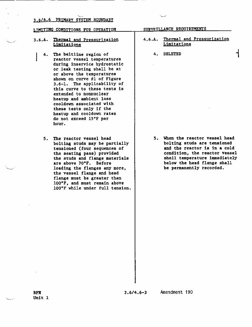
3.6/4.6 PRIMARY SYSTEM BOUNDARY
QTTD�1TTT.T.AN(R P�ATTTP1!MT�NTRLj±IIL±11 ~ ~ ~ ~ ~ ~ ~ CD~rT..Ar oJIUL±LJrnUIREMENTS..'L1_______________________________
3.6.A. Thermal and PressurizationLimitations
I
3.6/4.6-3BFN Unit 1
4.6.A. Thermal and Pressurization Limitations
4. DELETED -I4. The beltline region of reactor vessel temperatures during inservice hydrostatic or leak testing shall be at or above the temperatures shown on curve #1 of Figure 3.6-1. The applicability of this curve to these tests is extended to nonnuclear heatup and ambient loss cooldown associated with these tests only if the heatup and cooldown rates do not exceed 15*F per hour.
5. The reactor vessel head bolting studs may be partially tensioned (four sequences of the seating pass) provided the studs and flange materials are above 700F. Before loading the flanges any more, the vessel flange and head flange must be greater than 1000F, and must remain above 100OF while under full tension.
5. When the reactor vessel head bolting studs are tensioned and the reactor is in a cold condition, the reactor vessel shell temperature immediately below the head flange shall be permanently recorded.
Amendment 190

3.6/4.6 PRIMARY SYSTEM BOUNDARY
LIMITING CONDITIONS FOR OPERATION
3.6.A Thermal and Pressurization Limitations (Cont'd)
BFN Unit 1
6. The pump in an idle recirculation loop shall not be started unless the temperatures of the coolant within the idle and operating recirculation loops are within 50°F of each other.
7. The reactor recirculation pumps shall not be started unless the coolant temperatures between the dome and the bottom head drain are within 1450F.
3.6/4.6-4
SURVEILLANCE REQUIREMENTS
4.6.A Thermal and Pressurization Limitations (Cont'd)
6. Prior to and during startup of an idle recirculation loop, the temperature of the reactor coolant in the operating and idle loops shall be permanently logged.
7. Prior to starting a recirculation pump, the reactor coolant temperatures in the dome and in the bottom head drain shall be compared and permanently logged.
Amendment 190

1 2 31200
Figure 3.6.-1 (BFN Unit 1)
�zIzH4'I1Z
i i i i i i i i I I I
I---44
I-4-
II
2001-1-4-4
200
OLT UP TEMPERATURE IIIIIIII1111111
300
MINIMUM TEMPERATURE (°F)
Curve No. 1 Minimum temperature for pressure tests such as required by Section Xl. Minimum temperature of 195 OF is required for test pressure of 1,100 psig.
Curve No. 2 Minimum temperature for mechanical heatup or cooldown following nuclear shutdown.
Curve No. 3 Minimum temperature for core operation (criticality) Includes additional margin required for 10CFR50, Appendix G, Par. IV.A.3 which became effective July 26, 1983.
Notes These curves Include sufficient margin to provide protection against feedwater nozzle degradation. The curves allow for shifts in RTNDT of the Reactor vessel beltrine materials, In accordance with Reg. Guide 1.99 Rev. 2, to
400 compensate for radiation embrittlement for 12 EFPY.
Figure 3.6-1
BFN 3.6/4.6-24 Unit 1
Amendment 190
1000I11
U, *'''r'' 11111111
800
I I I I I .
600
a. 0
CL Z LU i
D (0 Co" w a. aia:
c-
C-
400
0
0 100
I
i i m i i I
f • I I I11 i i i i i i i i i 11 i i i i
I
--- TT-1 I- 1 1 1 1
I1
i l l I ' I II A' L
"JI I Ii-iiii--
II IIIII

THIS PAGE INTENTIONALLY LEFT BLANK
BFN 3.6/4.6-25 Amendment 190 Unit 1

3.6/4.6 BASES
3.6.A/4.6.A Thermal and Pressurization Limitations
The reactor vessel has been analyzed for cyclic stresses caused by the
temperature and pressure transients that arise from reactor trips, normal
startup and shutdown, etc. The analysis assumed a maximum uniform heatup
and cooldown rate of 100*F per hour for normal startup and shutdown and
demonstrated that normal startup and shutdown cycles are within the
required stress limits of Section III of the ASME Boiler and Pressure Vessel Code (1965 Edition including Summer 1966 addenda).
The operating limit curves for the reactor vessel (see Figure 3.6-1) were
established in accordance with the requirements of 1OCFR50 Appendix G and
Appendix G of the Summer 1972 Addenda to Section III of the ASME Boiler and Pressure Vessel Code, 1971 Edition. The curves are based on a large postulated surface flaw, with a depth one-quarter of the vessel thickness, the referenced toughness, RTNDT, and the stress intensity factors for the reactor vessel components.
The fracture toughness of ferritic steels decreases with exposure to fast neutrons (E > 1 MeV) and therefore, initial values of RTNDT have been adjusted to account for radiation embrittlement in the beltline region of the reactor vessel where neutron fluences are greater than 1017 n/cm2 .
An adjusted reference temperature based on neutron fluence, copper content, nickel content, and initial RTNDT for the controlling material was established using the methodology of Regulatory Guide 1.99, Revision 2, "Radiation Embrittlement of Reactor Vessel Materials." The pressure-temperature limit curve, Figure 3.6-1, Curves 1, 2, and 3,
includes a shift in RTNDT caused by the fluence corresponding to 12 effective full power years (EFPY) of operation.
Radiation embrittlement of the reactor vessel materials will be monitored periodically during operation by removing and evaluating, irradiation
flux wires and Charpy impact specimens contained in capsules installed near the inside wall of the reactor vessel in the core region. After the first refueling outage, flux wires were removed and evaluated. The data were used to verify calculated neutron fluence and to predict cumulative neutron fluence after 12 EFPY. Capsules that are withdrawn in the future will contain flux wires and Charpy impact specimens. Data derived from these specimens will be used as input to future radiation embrittlement evaluations that will account for neutron fluences above those corresponding to 12 EFPY.
BFN 3.6/4.6-26 Amendment 190 Unit 1

3.6/4.6 BASES
3.6.A/4.6.A (Cont'd) d
TVA letter dated May 15, 1987, proposed to withdraw the first set of reactor surveillance specimens from each reactor vessel at the end of each unit's cycle which most closely approximates 8.0 EFPY of operation. The reasoning was the development of an integrated surveillance program related to estimated fluence obtained from reactor vessel specimens prior to 8.0 EFPY would be premature because it would be based only on extrapolations of limited dosimetry measurements taken from unit 1 during the first cycle of operation. Dosimetry measurements for 8.0 EFPY would be more credible than cycle 1 dosimetry data. NRC letter dated December 2, 1988, stated that BFN could withdraw the first reactor vessel specimen from each reactor vessel at the end of each unit's cycle of operation that most closely approximates 8.0 EFPY of operation. After withdrawal of each unit's first sample, the remaining specimens will be withdrawn every 6.0 EFPY thereafter.
As described in paragraph 4.2.5 of the Safety Analysis Report, detailed stress analyses have been made on the reactor vessel for both steady-state and transient conditions with respect to material fatigue. The results of these analyses are compared to allowable stress limits. Requiring the coolant temperature in an idle recirculation loop to be within 50*F of the operating loop temperature before a recirculation pump is started assures that the changes in coolant temperature at the reactor vessel nozzles and bottom head region are acceptable.
The coolant in the bottom of the vessel is at a lower temperature than that in the upper regions of the vessel when there is no recirculation flow. This colder water is forced up when recirculation pumps are started. This will not result in stresses which exceed ASME Boiler and Pressure Vessel Code, Section III limits when the temperature differential is not greater than 1450 F.
The requirements for full tension boltup of the reactor vessel closure are based on the NDT temperature plus 600F. This is derived from the requirements of the ASME code to which the vessel was built. The NDT temperature of the closure flanges, adjacent head, and shell material is a maximum of 40OF and a maximum of 10OF for the stud material. Therefore, the minimum temperature for full tension boltup is 40OF plus 60OF for a
BFN 3.6/4.6-27 Amendment 190 Unit 1

3.6/4.6 BASES
3.6.A/4.6.A (Cont'd)
total of 1000F. The partial boltup is restricted to the full loading of eight studs at 70 0 F, which is stud NDT temperature (10*F) plus 600F. The
neutron radiation fluence at the closure flanges is well below 1017 nvt I 1 Mev; therefore, radiation effects will be minor and will not influence this temperature.
3.6.B/4.6.B Coolant Chemistry
Materials in the primary system are primarily 304 stainless steel and the
Zircaloy cladding. The reactor water chemistry limits are established to
prevent damage to these materials. Limits are placed on conductivity and chloride concentrations. Conductivity is limited because it is
continuously measured and gives an indication of abnormal conditions and
the presence of unusual materials in the coolant. Chloride limits are
specified to prevent stress corrosion cracking of stainless steel.
Zircaloy does not exhibit similar stress corrosion failures. However, there are some operating conditions under which the dissolved oxygen content of the reactor coolant water could be higher than .2-.3 ppm, such as reactor STARTUP and Hot Standby. During these periods, the most
restrictive limits for conductivity and chlorides have been established. When steaming rates exceed 100,000 lb/hr, boiling deaerates the reactor water. This reduces dissolved oxygen concentration and assures minimal
chloride-oxygen content, which together tend to induce stress corrosion cracking.
When conductivity is in its normal range, pH and chloride and other
impurities affecting conductivity must also be within their normal range.
When conductivity becomes abnormal, then chloride measurements are made to
determine whether or not they are also out of their normal operating values. This would not necessarily be the case. Conductivity could be
high due to the presence of a neutral salt which would not have an effect
on pH or chloride. In such a case, high conductivity alone is not a cause
for shutdown. In some types of water-cooled reactors, conductivities are in fact high due to purposeful addition of additives. In the case of
BWRs, however, where no additives are used and where near neutral pH is
maintained, conductivity provides a very good measure of the quality of
the reactor water. Significant changes therein provide the operator with
a warning mechanism so he can investigate and remedy the condition causing
the change before limiting conditions, with respect to variables affecting
the boundaries of the reactor coolant, are exceeded. Methods available to
the operator for correcting the off-standard condition include operation of the reactor cleanup system, reducing the input of impurities and placing the reactor in the Cold Shutdown condition. The major benefit of
Cold Shutdown is to reduce the temperature dependent corrosion rates and
provide time for the cleanup system to reestablish the purity of the
reactor coolant.
The conductivity of the reactor coolant is continuously monitored. The
samples of the coolant which are taken every 96 hours will serve as a
reference for calibration of these monitors and is considered adequate to
assure accurate readings of the monitors. If conductivity is within its
BFN 3.6/4.6-281 AMENDMERwG. 170 unit 1

3.6/4.6 BASES
3.6.B/4.6.B (Cont'd)
normal range, chlorides and other impurities will also be within their normal ranges. The reactor coolant samples will also be used to determine the chlorides. Therefore, the sampling frequency is considered adequate to detect long-term changes in the chloride ion content. Daily sampling is performed when increased chloride concentrations are most probable. Reactor coolant sampling is increased to once per shift when the continuous conductivity monitor is unavailable.
The basis for the equilibrium coolant iodine activity limit is a computed dose to the thyroid of 36 rem at the exclusion distance during the two-hour period following a steam line break. This dose is computed with the conservative assumption of a release of 140,000 lbs of coolant prior to closure of the isolation valves, and a X/Q value of 3.4 x 10⁻⁴ Sec/m 3 .
The maximum activity limit during a short term transient is established from consideration of a maximum iodine inhalation dose less than 300 rem. The probability of a steam line break accident coincident with an iodine concentration transient is significantly lower than that of the accident alone, since operation of the reactor with iodine levels above the equilibrium value is limited to 5 percent of total operation.
The sampling frequencies are established in order to detect the occurrence of an iodine transient which may exceed the equilibrium concentration limit, and to assure that the maximum coolant iodine concentrations are not exceeded. Additional sampling is required following power changes and off-gas transients, since present data indicate that the iodine peaking phenomenon is related to these events.
3.6.C/4.6.C Coolant Leakage
Allowable leakage rates of coolant from the reactor coolant system have been based on the predicted and experimentally observed behavior of cracks in pipes and on the ability to makeup coolant system leakage in the event of loss of offsite ac power. The normally expected background leakage due to equipment design and the detection capability for determining coolant system leakage were also considered in establishing the limits. The behavior of cracks in piping systems has been experimentally and analytically investigated as part of the USAEC sponsored Reactor Primary Coolant System Rupture Study (the Pipe Rupture Study). Work utilizing the data obtained in this study indicates that leakage from a crack can be detected before the crack grows to a dangerous or critical size by mechanically or thermally induced cyclic loading, or stress corrosion cracking or some other mechanism characterized by gradual crack growth. This evidence suggests that for leakage somewhat greater than the limit specified for unidentified leakage, the probability is small that imperfections or cracks associated with such leakage would grow rapidly. However, the establishment of allowable unidentified leakage greater than that given in 3.6.C on the basis of the data presently available would be premature because of uncertainties associated with the data. For leakage of the order of five gpm, as specified in 3.6.C, the experimental and analytical data
BFN 3.6/4.6-29 AMENDMENT NO. 1 70 Unit 1
10'P UNITED STATES . NUCLEAR REGULATORY COMMISSION
WASHINGTON. D. C. 20555
TENNESSEE VALLEY AUTHORITY
DOCKET NO. 50-260
BROWNS FERRY NUCLEAR PLANT, UNIT 2
AMENDMENT TO FACILITY OPERATING LICENSE
Amendment No. 205 License No. DPR-52
I. The Nuclear Regulatory Commission (the Commission) has found that:
A. The application for amendment by Tennessee Valley Authority (TVA), the licensee, dated July 19, 1991, including supplemental information from TVA letter dated October 24, 1991, complies with the standards and requirements of the Atomic Energy Act of 1954, as amended (the Act), and the Commission's rules and regulations set forth in 10 CFR Chapter I;
B. The facility will operate in conformity with the application, the provisions of the Act, and the rules and regulations of the Commission;
C. There is reasonable assurance (i) that the activities authorized by this amendment can be conducted without endangering the health and safety of the public, and (ii) that such activities will be conducted in compliance with the Commission's regulations;
D. The issuance of this amendment will not be inimical to the common defense and security or to the health and safety of the public; and
E. The issuance of this amendment is in accordance with 10 CFR Part 51 of the Commission's regulations and all applicable requirements have been satisfied.

-2-
2. Accordingly, the license is amended by changes to the Technical Specifications as indicated in the attachment to this license amendment and paragraph 2.C.(2) of Facility Operating License No. DPR-52 is hereby amended to read as follows:
(2) Technical Specifications
The Technical Specifications contained in Appendices A and B, as revised through Amendment No. 205, are hereby incorporated in the license. The licensee shall operate the facility in accordance with the Technical Specifications.
3. This license amendment is effective as of its date of issuance and shall be implemented within 30 days from the date of issuance.
FOR THE NUCLEAR REGULATORY COMMISSION
Frederick J. He don, Director Project Directorate 11-4 Division of Reactor Projects - I/II Office of Nuclear Reactor Regulation
Attachment: Changes to the Technical
Specifications
Date of Issuance: January 8, 1993

ATTACHMENT TO LICENSE AMENDMENT NO. 205
FACILITY OPERATING LICENSE NO. DPR-52
DOCKET NO. 50-260
Revise the Appendix below and inserting captioned amendment change. Overleaf* completeness.
A Technical Specifications by removing the pages identified the enclosed pages. The revised pages are identified by the number and contain marginal lines indicating tlt area of and spillover** pages are provided to maintain document
REMOVE INSERT
vii viii 3.6/4.6-3 3.6/4.6-4 3.6/4.6-24 3.6/4.6-25 3.6/4.6-26 3.6/4.6-27 3.6/4.6-28 3.6/4.6-29
vii* viii 3.6/4.6-3 3.6/4.6-4* 3.6/4.6-24 3.6/4.6-25* 3.6/4.6-26 3.6/4.6-27 3.6/4.6-28** 3.6/4,6-29**

Table
4.2.E
4.2.F
4.2.G
4.2.H
4.2.J
4.2.K
4.2.L
3.5-1
3.5.1
4.9.A
4.9 .A.4.C
3.11.A
3.l1.B
3. 11. C
3.11.D
6.2.A
LIST OF TABLES (Cont'd)'
Title
Minimum Test and Calibration Frequency for DrywellLeak Detection Instrumentation ...
Minimum Test and Calibration Frequency for Surveillance Instrumentation .............
Surveillance Requirements for Control Room Isolation Instrumentation . . . . ......
Minimum Test and Calibration Frequency for Flood Protection Instrumentation ...........
Seismic Monitoring Instrument Surveillance Requirements. . . . . . . ..........
Radioactive Gaseous Effluent Instrumentation Surveillance. . ................
ATWS-Recirculation Pump Trip (RPT)
Instrumentation Surveillance . . . . . ....
Minimum RHRSW and EECW Pump Assignment. . ...
MAPLHGR Versus Average Planar Exposure .......
Diesel Generator Reliability .... ...........
Voltage Relay Setpoints/Diesel Generator Start.
Fire Detection Instrumentation .............
Spray/Sprinkler Systems . ...........
Hose Stations ........... ..................
Yard Fire Hydrants and Fire Hose Houses . ...
Minimum Shift Crew Requirements . . . . . ...
• • I D • •
BFN vii Unit 2
AMENDMENT NO. 2 04, 205
Page No.
3.2/4.2-53
3.2/4.2-54
3.2/4.2-56
3.2/4.2-57
3.2/4.2-58
3.2/4.2-62
3.2/4.2-63a
3.5/4.5-11
3.5/4.5-21
3.9/4.9-16
3.9/4.9-18
3.11/4.11-14
3.11/4.11-17
3.11/4.11-18
3.11/4.11-20
6.0-4
-I

LIST OF ILLUSTRATIONS
Figure
2.1.1
2.1-2
4.1-1
4.2-1
3.5.K-I
3.5.M-I
3.5.2
3.6-1
4.8.1.a
4.8.1.b
viii
Page No.Title
APRM Flow Reference Scram and APRM Rod Block Settings ........... ...................
APRM Flow Bias Scram Vs. Reactor Core Flow . .
Graphical Aid in the Selection of an Adequate Interval Between Tests .... .............
System Unavailability ............... ..
MCPR Limits. . .................
BFN Power/Flow Stability Regions ...........
Kf Factor .................. . ...
Minimum Temperature OF Above Change in Transient Temperature. . . . . . . . . . ..
Gaseous Release Points and Elevations ....
Land Site Boundary ........... ...
Amendment 205
1.1/2.1-6
1.1/2.1-7
3.1/4.1-13
3.2/4.2-64
3.5/4.5-22
3.5/4.5-22a
3.5/4.5-23
3.6/4.6-24
3.8/4.8-10
3.8/4.8-11
�1
BFN Unit 2

3.6/4.6 PRIMARY SYSTEM BOUNDARY
T TMT1 TItU•-MV 1 -"Tn•PT1'T ' r'D tl'f lA'TnT' QTTDArVTT.T.AW11 PrfTTTP.MVNT.RJ &LM.ALAX.r .- L1LJ. J.JL1U A; JI Jr.;,l.fJ. 1 A,' 'C' 1
3.6.A. Thermal and Pressurization Limitations (Cont'd)
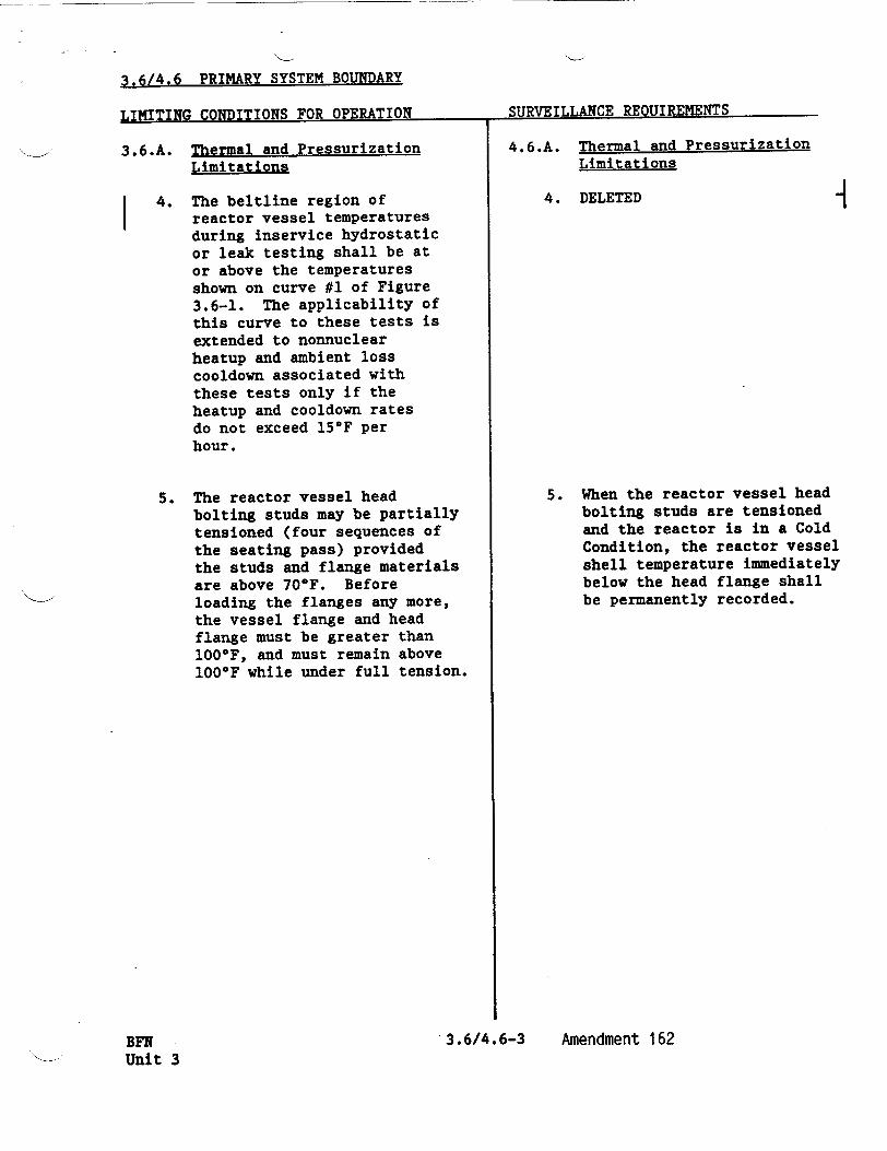
4. The beltline region of reactor vessel temperatures during inservice hydrostatic or leak testing shall be at or above the temperatures shown on curve #1 of Figure 3.6-1. The applicability of this curve to these tests is extended to nonnuclear heatup and ambient loss cooldown associated with these tests only if the heatup and cooldown rates do not exceed 15*F per hour.
5. The reactor vessel head bolting studs may be partially tensioned (four sequences of the seating pass) provided the studs and flange materials are above 700F. Before loading the flanges any more, the vessel flange and head flange must be greater than 100*F, and must remain above 100°F while under full tension.
3.6/4.6-3BFN Unit 2
4.6.A. Thermal and Pressurization Limitations (Cont 'd)
4. DELETED
5. When the reactor vessel head bolting studs are tensioned and the reactor is in a cold condition, the reactor vessel shell temperature immediately below the head flange shall be permanently recorded.
Amendment 205

3.6/4.6 PRIMARY b.•TEM BOUNDARY
T.TMTI'TNfC (•ATUTTTANN 1fP• APPPATTON SURVEILLANCE REOUIREMENTS
3.6.A Thermal and Pressurization Limitations (Cont'd)
6. The pump in an idle recirculation loop shall not be started unless the temperatures of the coolant within the idle and operating recirculation loops are within 50OF of each other.
7. The reactor recirculation pumps shall not be started unless the coolant temperatures between the dome and the bottom head drain are within 145*F.
3.6/4.6-4
4.6.A Thermal and Pressurization Limitations (Cont'd)
6. Prior to and during startup of an idle recirculation loop, the temperature of the reactor coolant in the operating and idle loops shall be permanently logged.
7. Prior to starting a recirculation pump, the reactor coolant temperatures in the dome and in the'bottom head drain shall be compared and permanently logged.
Amendment 205BFN Unit
T.TMT'rTNr- rnTTnTTTON.R rop nurvATION SURVEILLANCE REQUIREMENTS --------- r-
2

1 2 3
I-
.I I I I . . . I . . . . .
I I . 1 I I I i III
. . . . . . .
I 1 i I I I i M I I
20
;BOLT UP TEMPERATURE
0 300
MINIMUM TEMPERATURE (°F)
1200
0
a.
D CIO CO W a: CL
Figure 3.6-1
BFN 3.6/4.6-24 Unit 2
Amendment 205
. .1
1000
800
EIIE
Notes These curves Include sufficient margin to provide protection against feedwater nozzle degradation. The curves allow for shifts in RTNDT of the Reactor vessel beltrine materials, In accordance with Reg. Guide 1.99 Rev. 2, to compensate for radiation embrittlement for 12 EFPY.
600 I II1 1111: li Ii
a-
400
200
0
0 100
Rgure 3.6.-1 (BFN Units 2 and 3)
Curve No. 1 Minimum temperature for pressure tests such as required by Section XI. Minimum temperature of 185 °F is required for test pressure of 1,100 psig.
Curve No. 2 Minimum temperature for mechanical heatup or cooldown following nuclear shutdown.
Curve No. 3 Minimum temperature for core operation (criticality) Includes additional margin required for 10CFR50, Appendix G, Par. IV.A.3 which became effective July 26, 1983.
ý ý . . I . II
ý . I .I I I I I .
II I
I
I I I I
/"'"'""i'iT II •IIIA
L I L
llllllllfl[l!
F1I I I I II I I I I I

THIS PAGE INTENTIONALLY LEFT BLANK
d
.3.6/4.6-25BFN Unit 2
Amendment 205
3.6/4.6 BASES
3.6.A/4.6.A Thermal and Pressurization Limitations
The reactor vessel has been analyzed for cyclic stresses caused by the temperature and pressure transients that arise from reactor trips, normal startup and shutdown, etc. The analysis assumed a maximum uniform heatup and cooldown rate of 100OF per hour for normal startup and shutdown and demonstrated that normal startup and shutdown cycles are within the required stress limits of Section III of the ASME Boiler and Pressure Vessel Code (1965 Edition including Summer 1966 addenda).
The operating limit curves for the reactor vessel (see Figure 3.6-1) were established in accordance with the requirements of 10CFR5O Appendix G and Appendix G of the Summer 1972 Addenda to Section III of the ASME Boiler and Pressure Vessel Code, 1971 Edition. The curves are based on a large postulated surface flaw, with a depth one-quarter of the vessel thickness, the referenced toughness, RTNDT, and the stress intensity factors for the reactor vessel components.
The fracture toughness of ferritic steels decreases with exposure to fast neutrons (E > 1 MeV) and therefore, initial values of RTNDT have been adjusted to account for radiation embrittlement in the beltline region of the reactor vessel where neutron fluences are greater than 1017 n/cm2 . An adjusted reference temperature based on neutron fluence, copper content, nickel content, and initial RTNDT for the controlling material was established using the methodology of Regulatory Guide 1.99, Revision 2, "Radiation Embrittlement of Reactor Vessel Materials." The pressure-temperature limit curve, Figure 3.6-1, Curves 1,,2, and 3, includes a shift in RTNDT caused by the fluence corresponding to 12 effective full power years (EFPY) of operation.
Radiation embrittlement of the reactor vessel materials will be monitored periodically during operation by removing and evaluating, irradiation flux wires and Charpy impact specimens contained in capsules installed near the inside wall of the reactor vessel in the core region. After the first refueling outage, flux wires were removed and evaluated. The data were used to verify calculated neutron fluence and to predict cumulative neutron fluence after 12 EFPY. Capsules that are withdrawn in the future will contain flux wires and Charpy impact specimens. Data derived from these specimens will be used as input to future radiation embrittlement evaluations that will account for neutron fluences above those corresponding to 12 EFPY.
BFN 3.6/4.6-26 Amendment 205 Unit 2

3.6/4.6 BASES
3.6.A/4.6.A (Cont'd)
TVA letter dated May 15, 1987, proposed to withdraw the first set of reactor surveillance specimens from each reactor vessel at the end of each unit's cycle which most closely approximates 8.0 EFPY of operation. The reasoning was the development of an integrated surveillance program related to estimated fluence at this time would be premature because it would be based only on extrapolations of limited dosimetry measurements taken from unit 1 during the first cycle. Dosimetry measurements for 8.0 EFPY would be more credible than cycle 1 dosimetry data. NRC letter dated December 2, 1988, agreed and stated that BFN could withdraw the first specimen from each reactor vessel at the end of each unit's cycle of operation most closely approximates 8.0 EFPY of operation. After withdrawal of each unit's first sample, the remaining specimens will be withdrawn every 6.0 EFPY thereafter.
As described in paragraph 4.2.5 of the Safety Analysis Report, detailed stress analyses have been made on the reactor vessel for both steady-state and transient conditions with respect to material fatigue. The results of these analyses are compared to allowable stress limits. Requiring the coolant temperature in an idle recirculation loop to be within 50*F of the operating loop temperature before a recirculation pump is started assures that the changes in coolant temperature at the reactor vessel nozzles and bottom head region are acceptable.
The coolant in the bottom of the vessel is at a lower temperature than that in the upper regions of the vessel when there is no recirculation flow. This colder water is forced up when recirculation pumps are started. This will not result in stresses which exceed ASME Boiler and Pressure Vessel Code, Section III limits when the temperature differential is not greater than 145 0 F.
The requirements for full tension boltup of the reactor vessel closure are based on the NDT temperature plus 600F. This is derived from the requirements of the ASME code to which the vessel was built. The NDT temperature of the closure flanges, adjacent head, and shell material is a maximum of 400F and a maximum of 10OF for the stud material. Therefore, the minimum temperature for full tension boltup is 40*F plus 60*F for a total of 1000F. The partial boltup is restricted to the full loading of
BFN 3.6/4.6-27 Amendment 205 Unit 2

3.6/4.6 BASES
3.6.A/4.6.A (Cont'd)
eight studs at 700F, which is stud NDT temperature (10°F) plus 600F. The neutron radiation fluence at the closure flanges is well below 1017
nvt 1 1 Mev; therefore, radiation effects will be minor and will not influence this temperature.
3.6.B/4.6.B Coolant Chemistry
Materials in the primary system are primarily 304 stainless steel and the Zircaloy cladding. The reactor water chemistry limits are established to prevent damage to these materials. Limits are placed on conductivity and chloride concentrations. Conductivity is limited because it is continuously measured and gives an indication of abnormal conditions and the presence of unusual materials in the coolant. Chloride limits are specified to prevent stress corrosion cracking of stainless steel.
Zircaloy does not exhibit similar stress corrosion failures. However, there are some operating conditions under which the dissolved oxygen content of the reactor coolant water could be higher than .2-.3 ppm, such as reactor startup and hot standby. During these periods, the most restrictive limits for conductivity and chlorides have been established. When steaming rates exceed 100,000 lb/hr, boiling deaerates the reactor water. This reduces dissolved oxygen concentration and assures minimal chloride-oxygen content, which together tend to induce stress corrosion cracking.
When conductivity is in its normal range, pH and chloride and other impurities affecting conductivity must also be within their normal range. When conductivity becomes abnormal, then chloride measurements are made to determine whether or not they are also out of their normal operating values. This would not necessarily be the case. Conductivity could be high due to the presence of a neutral salt which would not have an effect on pH or chloride. In such a case, high conductivity alone is not a cause for shutdown. In some types of water-cooled reactors, conductivities are in fact high due to purposeful addition of additives. In the case of BWRs, however, where no additives are used and where near neutral pH is maintained, conductivity provides a very good measure of the quality of the reactor water. Significant changes therein provide the operator with a warning mechanism so he can investigate and remedy the condition causing the change before limiting conditions, with respect to variables affecting the boundaries of the reactor coolant, are exceeded. Methods available to the operator for correcting the off-standard condition include operation of the reactor cleanup system, reducing the input of impurities and placing the reactor in the Cold Shutdown condition. The major benefit of Cold Shutdown is to reduce the temperature dependent corrosion rates and provide time for the cleanup system to reestablish the purity of the reactor coolant.
The conductivity of the reactor coolant is continuously monitored. The samples of the coolant which are taken every 96 hours will serve as a reference for calibration of these monitors and is considered adequate to assure accurate readings of the monitors. If conductivity is within
BFN 3.6/4.6-281 AMENDMENT NO. 17 0 Unit 2

3.6.B/4.6.B (Cont'd)
its normal range, chlorides and other impurities will also be within
their normal ranges. The reactor coolant samples will also be used to
determine the chlorides. Therefore, the sampling frequency is
considered adequate to detect long-term changes in the chloride ion
content. Daily sampling is performed when increased chloride
concentrations are most probable. Reactor coolant sampling is increased
to once per shift when the continuous conductivity monitor is
unavailable.
The basis for the equilibrium coolant iodine activity limit is a
computed dose to the thyroid of 36 rem at the exclusion distance during
the two-hour period following a steam line break. This dose is computed
with the conservative assumption of a release of 140,000 lbs of coolant
prior to closure of the isolation valves, and a X/Q value of 3.4 x 10⁻⁴
Sec/m3 .
The maximum activity limit during a short term transient is established from consideration of a maximum iodine inhalation dose less than
300 rem. The probability of a steam line break accident coincident with
an iodine concentration transient is significantly lower than that of the accident alone, since operation of the reactor with iodine levels above the equilibrium value is limited to 5 percent of total operation.
The sampling frequencies are established in order to detect the occurrence of an iodine transient which may exceed the equilibrium concentration limit, and to assure that the maximum coolant iodine
concentrations are not exceeded. Additional sampling is required following power changes and off-gas transients, since present data indicate that the iodine peaking phenomenon is related to these events.
3.6.C/4.6.C Coolant Leakaae
Allowable leakage rates of coolant from the reactor coolant system have been based on the predicted and experimentally observed behavior of
cracks in pipes and on the ability to makeup coolant system leakage in the event of loss of offsite ac power. The normally expected background leakage due to equipment design and the detection capability for determining coolant system leakage were also considered in establishing the limits. The behavior of cracks in piping systems has been experimentally and analytically investigated as part of the USAEC
sponsored Reactor Primary Coolant System Rupture Study (the Pipe Rupture Study). Work utilizing the data obtained in this study indicates that
leakage from a crack can be detected before the crack grows to a dangerous or critical size by mechanically or thermally induced cyclic loading, or stress corrosion cracking or some other mechanism characterized by gradual crack growth. This evidence suggests that for leakage somewhat greater than the limit specified for unidentified leakage, the probability is small that imperfections or cracks associated with such leakage would grow rapidly. However, the establishment of allowable unidentified leakage greater than that given in 3.6.C on the basis of the data presently available would be premature because of uncertainties associated with the data. For leakage of the order of
B'Il 3.6/4.6-29 j AMENnMMI NO. 17 0 Unit 2
3.6/4.6 BASES

0 UNITED STATES 5) c •NUCLEAR REGULATORY COMMISSION
,WASHINGTON, D. C. 20555
TENNESSEE VALLEY AUTHORITY
DOCKET NO. 50-296
BROWNS FERRY NUCLEAR PLANT, UNIT 3
AMENDMENT TO FACILITY OPERATING LICENSE
Amendment No. 162 License No. DPR-68
1. The Nuclear Regulatory Commission (the Commission) has found that:
A. The application for amendment by Tennessee Valley Authority (TVA), the licensee, dated July 19, 1991, including supplemental information from TVA letter dated October 24, 1991, complies with the standards and requirements of the Atomic Energy Act of 1954, as amended (the Act), and the Commission's rules and regulations set in 10 forth in 10 CFR Chapter I;
B. The facility will operate in conformity with the application, the provisions of the Act, and the rules and regulations of the Commission;
C. There is reasonable assurance (i) that the activities authorized by this amendment can be conducted without endangering the health and safety of the public, and (ii) that such activities will be conducted in compliance with the Commission's regulations;
D. The issuance of this amendment will not be inimical to the common defense and security or to the health and safety of the public; and
E. The issuance of this amendment is in accordance with 10 CFR Part 51 of the Commission's regulations and all applicable requirements have been satisfied.

-2-
2. Accordingly, the license is amended by changes to the Technical Specifications as indicated in the attachment to this license amendment and paragraph 2.C.(2) of Facility Operating License No. DPR-68 is hereby amended to read as follows:
(2) Technical Specifications
The Technical Specifications contained in Appendices A and B, as revised through Amendment No. 162, are hereby incorporated in the license. The licensee shall operate the facility in accordance with the Technical Specifications.
3. This license amendment is effective as of its date of issuance and shall be implemented within 30 days from the date of issuance.
FOR THE NUCLEAR REGULATORY COMMISSION
Frederick J. Heb on, Director Project Directorate 11-4 Division of Reactor Projects - I/II Office of Nuclear Reactor Regulation
Attachment: Changes to the Technical
Specifications
Date of Issuance: January 8, 1993

ATTACHMENT TO LICENSE AMENDMENT NO. 162
FACILITY OPERATING LICENSE NO. DPR-68
DOCKET NO. 50-296
Revise the Appendix below and inserting captioned amendment change. Overleaf* completeness.
A Technical Specifications by removing the pages identified the enclosed pages. The revised pages are identified by the number and contain marginal lines indicating the area of and spillover** pages are provided to maintain document
REMOVE INSERT
vii viii 3.6/4.6-3 3.6/4.6-4 3.6/4.6-24 3.6/4.6-25 3.6/4.6-26 3.6/4.6-27 3.6/4.6-28 3.6/4.6-29
vii* viii 3.6/4.6-3 3.6/4.6-4* 3.6/4.6-24 3.6/4.6-25* 3.6/4.6-26 3.6/4.6-27 3.6/4.6-28"* 3.6/4.6-29**

LIST OF TABLES (Cont'd)
Title
Minimum Test and Calibration Frequency for DrywellLeak Detection Instrumentation.
Page No.
S. . . . . .. . 3.2/4.2-52
4.2.F
4.2.G
4.2.H
4.2.J
4.2.K
4.2.L
3.5-1
3.5.1
4.9.A
4.9.A.4.C
3.11.A
3.1l.B
3.1l.C
3.11..D
6.2.A
Minimum Test and Calibration Frequency for Surveillance Instrumentation .... ...........
Surveillance Requirements for Control Room Isolation Instrumentation ..... .............
Minimum Test and Calibration Frequency for Flood Protection Instrumentation . . . . ....
Seismic Monitoring Instrument Surveillance Requirements ........... ...................
Radioactive Gaseous Effluent Monitoring Instrumentation ......... .................
ATWS-Recirculation Pump Trip (RPT) Instrumentation Surveillance ..... ............
Minimum RHRSW and EECW Pump Assignment. . . ....
MAPLHGR Versus Average Planar Exposure. . . ....
Auxiliary Electrical System ............ . .
Voltage Relay Setpoints/Diesel Generator Start...
Fire Detection Instrumentation ........... ..
Spray/Sprinkler Systems ......................
Hose Stations . . . . . . . . . . . . . . . ....
Yard Fire Hydrants and Fire Hose Houses . . ....
Minimum Shift Crew Requirements . . . . . . ....
3.2/4.2-53
3.2/4.2-55
3.2/4.2-56
3.2/4.2-57
3.2/4.2-61
3.2/4.2-62a
3.5/4.5-11
3.5/4.5-21
3.9/4.9-15 1 3.9/4.9-17
3.11/4.11-14
3.11/4.11-18
3.11/4.11-20
3.11/4.11-22
6.0-4
BFN vii Unit 3
AMENDMENT NO. 161, 162
Table
4.2.E

LIST OF ILLUSTRATIONS
Fixure
2.1.1
2.1-2
4.1-1
4.2-1
3.5.K-1
3.5.2
3.6-1
4.8.1.a
4.8.1.b
viii
Title
APRM Flow Reference Scram and APRM Rod Block Settings ........................
APRM Flow Bias Scram Vs. Reactor Core Flow ....
Graphical Aid in the Selection of an Adequate Interval Between Tests ..... ...............
System Unavailability ...... ................
MCPR Limits. . ................ ..
Kf Factor ........................
Minimum Temperature OF Above Change in Transient Temperature ...... ...............
Gaseous Release Points and Elevation . . . . ...
Land Site Boundary . . . . . . . . . . . . . ...
Amendment 162
Page No.
1.1/2.1-6
1.1/2.1-7
3.1/4.1-12
3.2/4.2-63
3.5/4.5-25
3.5/4.5-26
3.6/4.6-24
3.8/4.8-10
3.8/4.8-11
AI
BFN Unit 3
3.6/4.6 PRIMARY SYSTEM BOUNDARY
TTDrTWTT.AU(. DIITTTPVRMIF.NT'kiML'LIJA I'I. JUAMAJ±±VI1o ZVL VrLLIJ~LA-L' ___________-- - w_________
3.6.A. Thermal and Pressurization Limitations
T4WFN
4.6.A.
I
Unit 3
Thermal and Pressurization Limitations
4. The beltline region of reactor vessel temperatures during inservice hydrostatic or leak testing shall be at or above the temperatures shown on curve #1 of Figure 3.6-1. The applicability of this curve to these tests is extended to nonnuclear heatup and ambient loss cooldown associated with these tests only if the heatup and cooldown rates do not exceed 15°F per hour.
5. The reactor vessel head bolting studs may be partially tensioned (four sequences of the seating pass) provided the studs and flange materials are above 700F. Before loading the flanges any more, the vessel flange and head flange must be greater than 1000F, and must remain above 100OF while under full tension.
3.6/4.6-3
4. DELETED
5. When the reactor vessel head bolting studs are tensioned and the reactor is in a Cold Condition, the reactor vessel shell temperature immediately below the head flange shall be permanently recorded.
Amendment 162

3 6/46 @ pRIMARY S•TEM BOUNDARY
T TMT'?TNVC (AInTTTAN5S FOR OPERATION
3.6.A Thermal and Pressurization Limitations (Cont'd)
6. The pump in an idle recirculation loop shall not be started unless the temperatures of the coolant within the idle and operating recirculation loops are within 50*F of each other.
7. The reactor recirculation pumps shall not be started unless the coolant temperatures between the dome and bottom head drain are within 145 0F.
3.6/4.6-4BFN Unit 3
I-
SURVEILLANCE REQUI REMENTS
4.6.A Thermal and PressurizationLimitations (Cont'd)
6. Prior to and during STARTUP of an idle recirculation loop, the temperature of the reactor coolant in the operating and idle loops shall be permanently logged.
7. Prior to starting a recirculation pump, the reactor coolant temperatures in the dome and in the bottom head drain shall be compared and permanently logged.
Amendment 162
T TMTrTNr- rnlWnTIrIONS FOR OPERATION SURVEILLANCE REQUIREMENTS

1 2 3 • I I I I I I i l l I I I
i. . . . . . . . . . . I
; I i 5 i i I I #Il I
I7 -I
Figure 3.6.-1 (BFN Units 2 and 3)
Curve No. 1 Minimum temperature for pressure tests such as required by Section XI. Minimum temperature of 185 OF is required for test pressure of 1,100 psig.
iiiztLlztttlzUlhlzt[4 I a I II. I 1
Curve No. 2 Minimum temperature for mechanical heatup or cooldown following nuclear shutdown.
Curve No. 3 Minimum temperature for core operation (criticality) Includes additional margin required for 10CFR50, Appendix G, Par. IV.A.3 which became effective July 26, 1983.
I FI I1 1 I LIII
I 111 1 i i
..I. . ....... .. I LL~ I I
200
OLT UP TEMPERATURE I I I I I I IL I I I I I II
0
200 300
MINIMUM TEMPERATURE (°F)
Notes These curves Include sufficient margin to provide protection against feedwater nozzle degradation. The curves allow for shifts in RTNDT of the Reactor vessel beltline materials, In accordance with Reg. Guide 1.99 Rev. 2, to compensate for radiation embrittlement for 12 EFPY.
Figure 3.6-1
BFN 3.6/4.6-24 Unit 3
Amendment 162
1200
I11111
111111111 I
1000 IlI I
I1=800U CL
z
cr
D (
a. a: 0
0.600
400
0 100
L. II I I IML
i II. . . . I I I i i I
-- - 1 . . . . . . . .I I I I I
S. . . . I
l l
. l . I
i z i i i i l I I
It"
I I I I I I
• = ,
Ill .... illllll
I I I
,1,,,. .....1
I

THIS PAGE INTENTIONALLY LEFT BLANK
A
3.6/4.6-25BFN Unit 3
Amendment 162
3.6/4.6 BASES
3.6.A/4.6.A Thermal and Pressurization Limitations
The reactor vessel has been analyzed for cyclic stresses caused by the
temperature and pressure transients that arise from reactor trips, normal
startup and shutdown, etc. The analysis assumed a maximum uniform heatup
and cooldown rate of 100OF per hour for normal startup and shutdown and
demonstrated that normal startup and shutdown cycles are within the
required stress limits of Section III of the ASME Boiler and Pressure
Vessel Code (1965 Edition including Summer 1966 addenda).
The operating limit curves for the reactor vessel (see Figure 3.6-1) were
established in accordance with the requirements of 1OCFR50 Appendix G and
Appendix G of the Summer 1972 Addenda to Section III of the ASME Boiler
and Pressure Vessel Code, 1971 Edition. The curves are based on a large
postulated surface flaw, with a depth one-quarter of the vessel
thickness, the referenced toughness, RTNDT, and the stress intensity
factors for the reactor vessel components.
The fracture toughness of ferritic steels decreases with exposure to fast
neutrons (E > 1 MeV) and therefore, initial values of RTNDT have been
adjusted to account for radiation embrittlement in the beltline region of
the reactor vessel where neutron fluences are greater than 1017 n/ýM2 .
An adjusted reference temperature based on neutron fluence, copper
content, nickel content, and initial RTNDT for the controlling material
was established using the methodology of Regulatory Guide 1.99, Revision
2, "Radiation Embrittlement of Reactor Vessel Materials." The
pressure-temperature limit curve, Figure 3.6-1, Curves 1, 2, and 3,
includes a shift in RTNDT caused by the fluence corresponding to 12
effective full power years (EFPY) of operation.
Radiation embrittlement of the reactor vessel materials will be monitored
periodically during operation by removing and evaluating, irradiation
flux wires and Charpy impact specimens contained in capsules installed
near the inside wall of the reactor vessel in the core region. After the
first refueling outage, flux wires were removed and evaluated. The data
were used to verify calculated neutron fluence and to predict cumulative
neutron fluence after 12 EFPY. Capsules that are withdrawn in the future
will contain flux wires and Charpy impact specimens. Data derived from
these specimens will be used as input to future radiation embrittlement
evaluations that will account for neutron fluences above those
corresponding to 12 EFPY.
BFN 3.6/4.6-26 Amendment 162
Unit 3
3.6/4.6 BASES
3.6.A/4.6.A (Cont'd)
TVA letter dated May 15, 1987, proposed to withdraw the first set of reactor surveillance specimens from each reactor vessel at the end of each unit's cycle which most closely approximates 8.0 EFPY of operation. The reasoning was the development of an integrated surveillance program related to estimated fluence at this time would be premature because it would be based only on extrapolations of limited dosimetry measurements taken from unit 1 during the first cycle. Dosimetry measurements for 8.0 EFPY would be more credible than cycle 1 dosimetry data. NRC letter dated December 2, 1988, agreed and stated that BFN could withdraw the first specimen from each reactor vessel at the end of each unit's cycle of operation most closely approximates 8.0 EFPY of operation. After withdrawal of each unit's first sample, the remaining specimens will be withdrawn every 6.0 EFPY thereafter.
As described in paragraph 4.2.5 of the Safety Analysis Report, detailed stress analyses have been made on the reactor vessel for both steady-state and transient conditions with respect to material fatigue. The results of these analyses are compared to allowable stress limits. Requiring the coolant temperature in an idle recirculation loop to be within 50OF of the operating loop temperature before a recirculation pump is started assures that the changes in coolant temperature at the reactor vessel nozzles and bottom head region are acceptable.
The coolant in the bottom of the vessel is at a lower temperature than that in the upper regions of the vessel when there is no recirculation flow. This colder water is forced up when recirculation pumps are started. This will not result in stresses which exceed ASME Boiler and Pressure Vessel Code, Section III limits when the temperature differential is not greater than 1450F.
The requirements for full tension boltup of the reactor vessel closure are based on the NDT temperature plus 60 0 F. This is derived from the requirements of the ASME code to which the vessel was built. The NDT temperature of the closure flanges, adjacent head, and shell material is a maximum of 40OF and a maximum of 10OF for the stud material. Therefore, the minimum temperature for full tension boltup is 40°F plus 60°F for a total of 1000F. The partial boltup is restricted to the full loading of
BFN 3.6/4.6-27 Amendment 162 Unit 3

3.6/4.6 BASES
3.6.A/4.6.A (Cont'd)
eight studs at 70*F, which is stud NDT temperature (10*F) plus 60*F. The neutron radiation fluence at the closure flanges is well below 1017 nvt 1 1 Mev; therefore, radiation effects will be minor and will not influence this temperature.
3.6.B/4.6.B Coolant Chemistry
Materials in the primary system are primarily 304 stainless steel and the Zircaloy cladding. The reactor water chemistry limits are established to prevent damage to these materials. Limits are placed on conductivity and chloride concentrations. Conductivity is limited because it is continuously measured and gives an indication of abnormal conditions and the presence of unusual materials in the coolant. Chloride limits are specified to prevent stress corrosion cracking of stainless steel.
Zircaloy does not exhibit similar stress corrosion failures. However, there are some operating conditions under which the dissolved oxygen content of the reactor coolant water could be higher than .2-.3 ppm, such as reactor startup and hot standby. During these periods, the most restrictive limits for conductivity and chlorides have been established. When steaming rates exceed 100,000 lb/hr, boiling deaerates the reactor water. This reduces dissolved oxygen concentration and assures minimal chloride-oxygen content, which together tend to induce stress corrosion cracking.
When conductivity is in its normal range, pH and chloride and other impurities affecting conductivity must also be within their normal range. When conductivity becomes abnormal, then chloride measurements are made to determine whether or not they are also out of their normal operating values. This would not necessarily be the case. Conductivity could be high due to the presence of a neutral salt which would not have an effect on pH or chloride. In such a case, high conductivity alone is not a cause for shutdown. In some types of water-cooled reactors, conductivities are in fact high due to purposeful addition of additives. In the case of BWRs, however, where no additives are used and where near neutral pH is maintained, conductivity provides a very good measure of the quality of the reactor water. Significant changes therein provide the operator with a warning mechanism so he can investigate and remedy the condition causing the change before limiting conditions, with respect to variables affecting the boundaries of the reactor coolant, are exceeded. Methods available to the operator for correcting the off-standard condition include operation of the reactor cleanup system, reducing the input of impurities and placing the reactor in the Cold Shutdown condition. The major benefit of Cold Shutdown is to reduce the temperature dependent corrosion rates and provide time for the cleanup system to reestablish the purity of the reactor coolant.
The conductivity of the reactor coolant is continuously monitored. The samples of the coolant which are taken every 96 hours will serve as a reference for calibration of these monitors and is considered adequate to assure accurate readings of the monitors. If conductivity is within
BFN 3.6/4.6-28 I AMENDMET NO. 14 Unit 3

3.6/4.6 BASES
3.6.B/4.6.B (Cont'd)
its normal range, chlorides and other impurities will also be within their normal ranges. The reactor coolant samples will also be used to determine the chlorides. Therefore, the sampling frequency is considered adequate to detect long-term changes in the chloride ion content. Daily sampling is performed when increased chloride concentrations are most probable. Reactor coolant sampling is increased to once per shift when the continuous conductivity monitor is unavailable.
The basis for the equilibrium coolant iodine activity limit is a computed dose to the thyroid of 30 rem at the exclusion distance during the two-hour period following a steam line break. This dose is computed with the conservative assumption of a release of 140,000 lbs of coolant prior to closure of the isolation valves, and a X/Q value of 2.9 x 10⁻⁴ Sec/m3 .
The maximum activity limit during a short term transient is established from consideration of a maximum iodine inhalation dose less than 300 rem. The probability of a steam line break accident coincident with an iodine concentration transient is significantly lower than that of the accident alone, since operation of the reactor with iodine levels above the equilibrium value is limited to 5 percent of total operation.
The sampling frequencies are established in order to detect the occurrence of an iodine transient which may exceed the equilibrium concentration limit, and to assure that the maximum coolant iodine concentrations are not exceeded. Additional sampling is required following power changes and off-gas transients, since present data indicate that the iodine peaking phenomenon is related to these events.
3.6.C/4.6.C Coolant Leakage
Allowable leakage rates of coolant from the reactor coolant system have been based on the predicted and experimentally observed behavior of cracks in pipes and on the ability to makeup coolant system leakage in the event of loss of offsite ac power. The normally expected background leakage due to equipment design and the detection capability for determining coolant system leakage were also considered in establishing the limits. The behavior of cracks in piping systems has been experimentally and analytically investigated as part of the USAEC sponsored Reactor Primary Coolant System Rupture Study (the Pipe Rupture Study). Work utilizing the data obtained in this study indicates that leakage from a crack can be detected before the crack grows to a dangerous or critical size by mechanically or thermally induced cyclic loading, or stress corrosion cracking or some other mechanism characterized by gradual crack growth. This evidence suggests that for leakage somewhat greater than the limit specified for unidentified leakage, the probability is small that imperfections or cracks associated with such leakage would grow rapidly. However, the establishment of allowable unidentified leakage greater than that given in 3.6.C on the basis of the data presently available would be premature because of uncertainties associated with the data. For leakage of the order of five gpm, as specified in 3.6.C, the experimental and analytical data
BFN 3.6/4.6-29 I Unit 3 AMENDMENTNO. 141