brookhaven graphite research reactor decommissioning · pdf filebrookhaven graphite research...
TRANSCRIPT
BGRR-071
Brookhaven Graphite Research Reactor Decommissioning Project
FINAL CANAL AND DEEP SOIL POCKETS EXCAVATION AND
REMOVAL COMPLETION REPORT
August 22, 2005
BROOKHAVEN NATIONAL LABORATORY BROOKHAVEN SCIENCE ASSOCIATES
Under Contract No. DE-AC02-98CH01886 with the UNITED STATES DEPARTMENT OF ENERGY

FINAL Canal and Deep Soil Pockets Excavation and Removal BGRR-071 Completion Report August 22, 2005
ii
EXECUTIVE SUMMARY
This report documents the completion of removal actions authorized by the United States Department of Energy (DOE) at Brookhaven National Laboratory (BNL) on the Brookhaven Graphite Research Reactor (BGRR). The work described herein was performed in accordance with the Comprehensive Environmental Recovery, Liability, and Compensation Act of 1980 (CERCLA) through the Interagency Agreement between the DOE, the United States Environmental Protection Agency, and the New York State Department of Environmental Conservation. The BGRR canal and deep soil pockets were removed in accordance with a Non-Time-Critical Removal Action Memorandum dated December 29, 2004. In summary, all removal activities delineated in the referenced Action Memorandum have been completed. The BGRR canal and contaminated deep soil pockets have been excavated and removed. Radiological surveys were completed to measure the extent of and document residual contamination. The excavated areas have been backfilled, compacted and covered with a temporary asphalt cap. All associated waste from these actions was packaged, transported and disposed at authorized radioactive, hazardous, and clean waste disposal facilities.

FINAL Canal and Deep Soil Pockets Excavation and Removal BGRR-071 Completion Report August 22, 2005
iii
TABLE OF CONTENTS EXECUTIVE SUMMARY ............................................................................................................ ii
LIST OF FIGURES ....................................................................................................................... iv
ACRONYMS, ABBREVIATIONS, AND UNITS OF MEASUREMENT................................... v
1.0 Introduction............................................................................................................................. 1
1.1 Purpose................................................................................................................................ 1
2.0 Site Description and History................................................................................................... 1
2.1 Brookhaven National Laboratory ....................................................................................... 1
2.2 Brookhaven Graphite Research Reactor............................................................................. 2
2.3 Stakeholder Participation .................................................................................................... 4
3.0 Removal activity ..................................................................................................................... 5
3.1 Objectives ........................................................................................................................... 5
3.2 Activities ............................................................................................................................. 5
3.3 As-left Condition .............................................................................................................. 12
3.4 Cost of Work..................................................................................................................... 12
4.0 Waste Management............................................................................................................... 12
4.1 Packaging, Transportation and Disposal of Waste ........................................................... 12
5.0 Lessons Learned.................................................................................................................... 13
6.0 References............................................................................................................................. 14 APPENDIX 1 - AS-LEFT RADIOLOGICAL SURVEYS.......................................................... 15 APPENDIX 2 - PICTORIAL REVIEW OF THE REMOVAL ACTIVITIES ............................ 20
FINAL Canal and Deep Soil Pockets Excavation and Removal BGRR-071 Completion Report August 22, 2005
iv
LIST OF FIGURES Figure 1. Location of Brookhaven National Laboratory ............................................................... 1 Figure 2. The BGRR Site Looking North...................................................................................... 2 Figure 3. Isometric Drawing of the BGRR Canal & Deep Pit....................................................... 4 Figure 4. BGD Secondary Cooling Air Bustle Excavated Contaminated Soil ............................. 9 Figure 5. Canal Structure Removal and Soil Excavation ............................................................ 10 Figure 6. Cooler Drain Sumps and Expansion Joint #4 Excavation............................................ 11

FINAL Canal and Deep Soil Pockets Excavation and Removal BGRR-071 Completion Report August 22, 2005
v
ACRONYMS, ABBREVIATIONS, AND UNITS OF MEASUREMENT
BAO Brookhaven Area Office BGD (BGRR) Below Ground Ducts BGRR Brookhaven Graphite Research Reactor BHG Brookhaven Group BHSO Brookhaven Site Office BNL Brookhaven National Laboratory BSA Brookhaven Science Associates CERCLA Comprehensive Environmental Response, Compensation, and Liability Act of
1980 DOE Department of Energy EE/CA Engineering Evaluation/Cost Analysis EPA U.S. Environmental Protection Agency ERD Environmental Restoration Division HEPA High Efficiency Particulate Air IAG Interagency Agreement mCi milliCuries mrem/hr millirem per hour NESHAP National Emission Standards of Hazard Air Pollutants NYSDEC New York State Department of Environmental Conservation

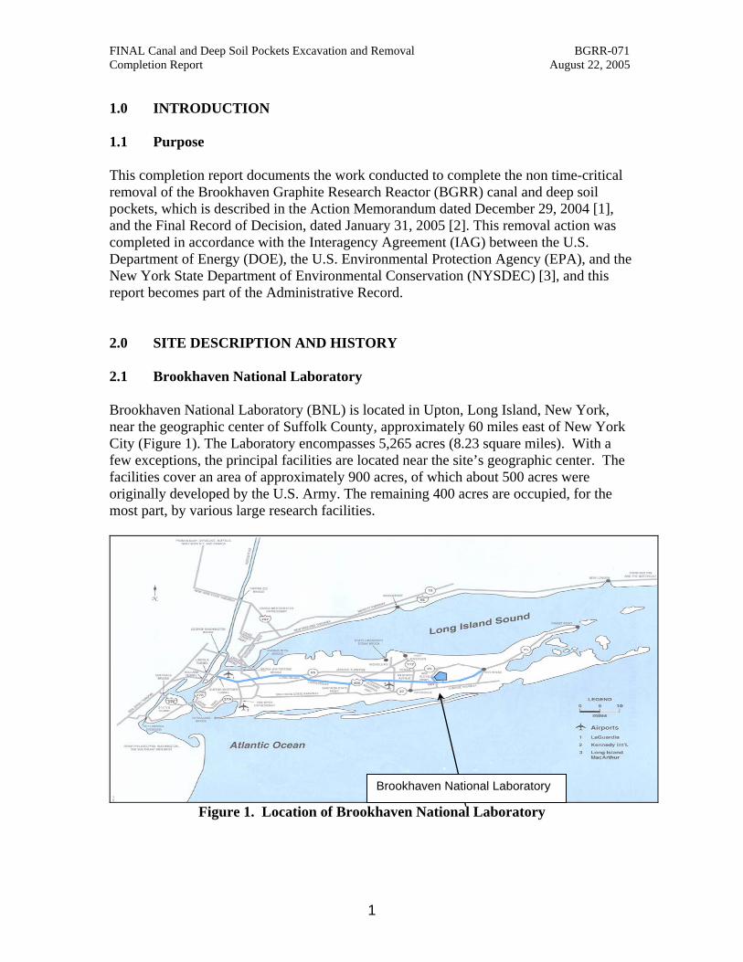
FINAL Canal and Deep Soil Pockets Excavation and Removal BGRR-071 Completion Report August 22, 2005 1.0 INTRODUCTION 1.1 Purpose This completion report documents the work conducted to complete the non time-critical removal of the Brookhaven Graphite Research Reactor (BGRR) canal and deep soil pockets, which is described in the Action Memorandum dated December 29, 2004 [1], and the Final Record of Decision, dated January 31, 2005 [2]. This removal action was completed in accordance with the Interagency Agreement (IAG) between the U.S. Department of Energy (DOE), the U.S. Environmental Protection Agency (EPA), and the New York State Department of Environmental Conservation (NYSDEC) [3], and this report becomes part of the Administrative Record. 2.0 SITE DESCRIPTION AND HISTORY 2.1 Brookhaven National Laboratory Brookhaven National Laboratory (BNL) is located in Upton, Long Island, New York, near the geographic center of Suffolk County, approximately 60 miles east of New York City (Figure 1). The Laboratory encompasses 5,265 acres (8.23 square miles). With a few exceptions, the principal facilities are located near the site’s geographic center. The facilities cover an area of approximately 900 acres, of which about 500 acres were originally developed by the U.S. Army. The remaining 400 acres are occupied, for the most part, by various large research facilities.
Figure 1. Location of Brookhaven National Laboratory
Brookhaven National Laboratory
1

FINAL Canal and Deep Soil Pockets Excavation and Removal BGRR-071 Completion Report August 22, 2005 BNL carries out basic and applied research in the fields of high-energy nuclear and solid-state physics, fundamental material and structure properties and the interactions of matter, nuclear medicine, biomedical, and environmental sciences, and selected energy technologies. 2.2 Brookhaven Graphite Research Reactor The BGRR was the world’s first reactor built for the sole purpose of providing neutrons for research. During its years of operation, it was one of the principal research reactors in the United States. Its construction was completed in August 1950, and the reactor reached initial criticality in the same month. The BGRR operated until June 10, 1968, when its operation was terminated and deactivation of the facility started. In June 1972, defueling and shipment of the fuel to the DOE’s Savannah River site was completed. The U.S. Atomic Energy Commission described the BGRR complex as being in a safe shutdown condition and it became a surplus facility within the DOE complex. From 1977 until 1997, portions of the facility were used as the BNL Science Museum. The BGRR was an air-cooled, graphite-moderated reactor located in Building 701, with supporting systems located in the Fan House (Building 704) and the Instrument House (Building 708). Figure 2 shows the BGRR facility looking north.
Figure 2. BGRR Facility Looking North
2

FINAL Canal and Deep Soil Pockets Excavation and Removal BGRR-071 Completion Report August 22, 2005 During reactor operations, outside cooling air was drawn across the reactor pile by cooling fans that were located in the fan house. Connecting the reactor to the fan house was ductwork that was constructed beneath the ground until it reached the instrument house, where it rose above ground, and connected to the exhaust fans that were located inside the fan house. After the reactor was shutdown, it was discovered that rainwater and melted snow leaked into this ductwork from various above ground penetrations. Eventually, this water leaked out of the ductwork through degraded joints and connections and contaminated the soil. Radiological characterization was performed at these areas, which identified the location and levels of the contamination in these areas that are referred to as deep soil pockets. The lower canal and canal house (Building 709), and water treatment house (Building 709A), and related systems and equipment were used to support BGRR refueling and fuel handling operations. BGRR refueling operations were performed from the south face of the reactor. The fuel elements would be withdrawn from the channels into the area between the reactor’s biological shield wall and pile face where they would drop into the deep pit. The deep pit was located inside of Building 701 beneath the ground floor and connected to the canal. The canal was also located beneath the building 701 and continued almost fifty feet underground east of the building 701 east wall. The canal/deep pit structure included a walkway at the upper level where workers could move the fuel using long-reach tools. Spent uranium fuel rods were segmented in the deep pit/canal system. Figure 3 depicts the canal and deep pit in an isometric view. Routine fuel-handling activities in connection with BGRR operation resulted in the radiological contamination of the canal, water treatment systems, water treatment house, as well as the associated piping systems and equipment. Based on BGRR operating history and radiological characterization, contaminated water was known to have leaked at the construction joint between the canal and Building 701, the bottom of the canal walkway sump, and other construction seams in the canal. The canal above grade house, the water treatment house, and related systems were removed by a previously authorized removal action [4], which was halted before completion. Figure 3 depicts the deep pit and canal in an isometric view.
3

FINAL Canal and Deep Soil Pockets Excavation and Removal BGRR-071 Completion Report August 22, 2005
Figure 3. Isometric Drawing of the Canal & Deep Pit
2.3 Stakeholder Participation
Stakeholders – including the public, regulators and BNL employees – were informed of and involved in the canal and deep soil pocket removal actions through several scheduled events and media releases. From the beginning, DOE has communicated with stakeholders about its plans for decommissioning of the BGRR and has solicited community input on the path forward. This public input was incorporated into the Record of Decision [2], which includes the removal actions documented herein.
4

FINAL Canal and Deep Soil Pockets Excavation and Removal BGRR-071 Completion Report August 22, 2005 3.0 REMOVAL ACTIVITY 3.1 Objectives The removal activities had the following objectives: Excavate and remove the canal concrete structure Excavate the deep soil pockets Restore the excavated areas Transport and dispose of the waste at an approved facility. Remove substantial portions of the sub-surface contamination without undermining
the surrounding buildings and structures Substantially reduce the potential hazards posed by the radiological inventory 3.2 Activities 3.2.1 Non-Time-Critical Removal Actions
These activities were performed as a Non-Time Critical Removal Action [1]. As part of this Removal Action, limits were established for re-use of overburden soil as backfill. Additionally, it was established that since removal actions were to be performed in congested work areas immediately adjacent to buildings and structures that would remain in place, excavation of contaminated soils and structures would be constrained by the DOE’s physical access to the work areas. It was established that the soil in the BGRR complex is Type C soil, which is a sandy loam soil. This soil type has a natural fallback of approximately 34 degrees. Therefore, the depth or grade of all excavations was limited to the horizontal line at which the 34 degree excavation slope intersected and potentially compromised buildings and structures. The completed work described below resulted in the substantial removal of sub-surface contamination without undermining the foundations of the surrounding buildings and structure as demonstrated by the “as-left” surveys (Appendix 1). Table 1 provides a comparison of soil and concrete expected to be removed to the actual volume of soil and concrete removed. 3.2.1.1 BGRR Deep Soil Pockets. Radiological characterization identified several pockets of contaminated soil beneath certain BGRR structures. The following locations were identified as areas containing pockets of soil contamination: Building 701 north pipe trench North below ground duct (BGD) cooler drain sump South BGD cooler drain sump North BGD cooler expansion joint #4 South BGD cooler expansion joint #4
5
FINAL Canal and Deep Soil Pockets Excavation and Removal BGRR-071 Completion Report August 22, 2005
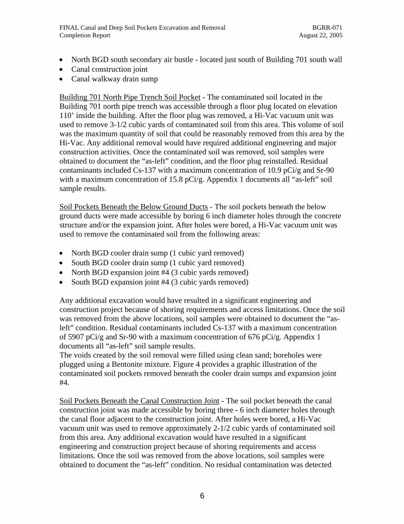
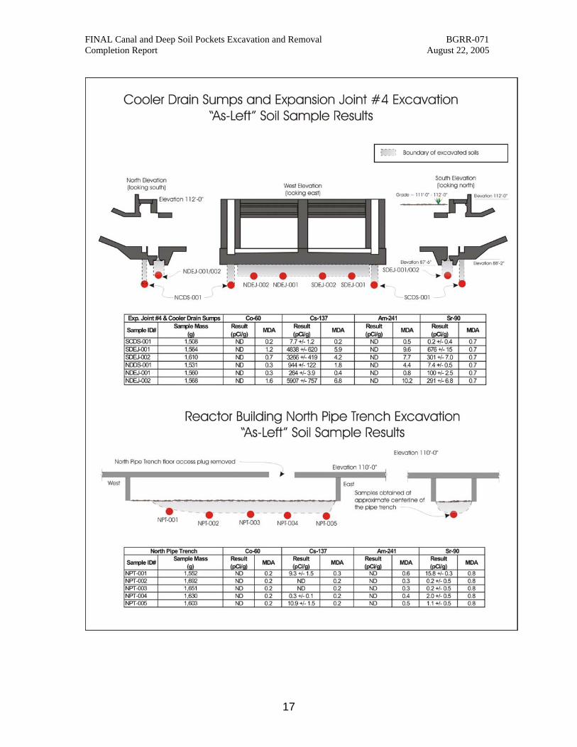
North BGD south secondary air bustle - located just south of Building 701 south wall Canal construction joint Canal walkway drain sump Building 701 North Pipe Trench Soil Pocket - The contaminated soil located in the Building 701 north pipe trench was accessible through a floor plug located on elevation 110’ inside the building. After the floor plug was removed, a Hi-Vac vacuum unit was used to remove 3-1/2 cubic yards of contaminated soil from this area. This volume of soil was the maximum quantity of soil that could be reasonably removed from this area by the Hi-Vac. Any additional removal would have required additional engineering and major construction activities. Once the contaminated soil was removed, soil samples were obtained to document the “as-left” condition, and the floor plug reinstalled. Residual contaminants included Cs-137 with a maximum concentration of 10.9 pCi/g and Sr-90 with a maximum concentration of 15.8 pCi/g. Appendix 1 documents all “as-left” soil sample results. Soil Pockets Beneath the Below Ground Ducts - The soil pockets beneath the below ground ducts were made accessible by boring 6 inch diameter holes through the concrete structure and/or the expansion joint. After holes were bored, a Hi-Vac vacuum unit was used to remove the contaminated soil from the following areas: North BGD cooler drain sump (1 cubic yard removed) South BGD cooler drain sump (1 cubic yard removed) North BGD expansion joint #4 (3 cubic yards removed) South BGD expansion joint #4 (3 cubic yards removed) Any additional excavation would have resulted in a significant engineering and construction project because of shoring requirements and access limitations. Once the soil was removed from the above locations, soil samples were obtained to document the “as-left” condition. Residual contaminants included Cs-137 with a maximum concentration of 5907 pCi/g and Sr-90 with a maximum concentration of 676 pCi/g. Appendix 1 documents all “as-left” soil sample results. The voids created by the soil removal were filled using clean sand; boreholes were plugged using a Bentonite mixture. Figure 4 provides a graphic illustration of the contaminated soil pockets removed beneath the cooler drain sumps and expansion joint #4. Soil Pockets Beneath the Canal Construction Joint - The soil pocket beneath the canal construction joint was made accessible by boring three - 6 inch diameter holes through the canal floor adjacent to the construction joint. After holes were bored, a Hi-Vac vacuum unit was used to remove approximately 2-1/2 cubic yards of contaminated soil from this area. Any additional excavation would have resulted in a significant engineering and construction project because of shoring requirements and access limitations. Once the soil was removed from the above locations, soil samples were obtained to document the “as-left” condition. No residual contamination was detected
6

FINAL Canal and Deep Soil Pockets Excavation and Removal BGRR-071 Completion Report August 22, 2005 below the Canal Construction Joint. Appendix 1 documents all “as-left” soil sample results.The voids created by the soil removal were filled using clean sand; boreholes were plugged using a Bentonite mixture. BGD Secondary Air Bustle Soil Pocket - The soil pocket located at the south bustle of the north below ground duct was located between 27 and 33 feet below grade. Prior to commencement of this work, an Excavation Plan was developed by a Professional Engineer to ensure safe work execution and to establish accurate soil and debris excavation volumes. To access and excavate this soil pocket a 12-foot diameter caisson was centered over the location of the pocket. Using a crane and clamshell bucket, the soil from inside the caisson was removed, allowing the caisson to advance downward. The soil that was excavated between grade elevation and 26 feet below grade was separated into 30 cubic yard stockpiles for reuse as clean overburden; each of the overburden stockpiles was surveyed to confirm that reuse criteria was met. Soil that was excavated below 26 feet below grade was loaded into waste containers as it was removed. Once the target depth of 33 feet below grade was reached, soil samples were obtained to document the “as-left” condition. No residual contamination was detected at Secondary Air Bustle. Appendix 1 documents all “as-left” soil sample results. In summary, 120 cubic yards of overburden soil was excavated and re-used as backfill in the BGD secondary air bustle location of soil contamination. A total of 40 cubic yards of contaminated soil was excavated and disposed of. Figure 5 provides a graphic illustration of the secondary air bustle evacuated contaminated soil pocket. 3.2.1.2 BGRR Canal Canal Excavation and Removal - An excavation plan for the excavation and removal of the canal was developed by a Professional Engineer. As part of the approved Excavation Plan, a new 20-inch thick reinforced concrete isolation wall was installed immediately adjacent to the point where the canal was to be cut for removal. Once the new wall concrete had cured and the concrete tested to verify strength requirements, soil excavation began. Soil from grade down to 10 feet below grade was assumed to be radiologically clean since previous soil removal had been done in most of the area. This clean overburden soil was separated into 30 cubic yard stockpiles for reuse as clean overburden; each of the overburden stockpiles was surveyed for radiological contaminants to confirm that reuse criteria was met. Once the excavation reached 10 feet below grade, demolition of the canal concrete structure commenced in conjunction with excavation of contaminated soil. The canal concrete structure was rubbled in place using an impact hammer fitted to a long-reach excavating machine. Once the concrete was rubbled, a second long reach excavator was used to excavate the concrete, which was mixed with soil, directly into the shipping containers. Throughout the excavation and demolition process, dust control measures such as application of fixative and water misting were employed. These measures, along with continuous air monitoring, assured that there was no release of airborne radiological contaminants. Excavation of the canal area was limited to four feet below the bottom of the canal structure (elevation 85’- 4”). The excavation was limited to this depth to prevent the natural fallback of the Type C soil
7

FINAL Canal and Deep Soil Pockets Excavation and Removal BGRR-071 Completion Report August 22, 2005 from undermining the Building 701 east wall line. Canal Walkway Sump Soil Pocket – Once the canal structure was removed, the contaminated soil in this area was accessible. Approximately two cubic yards of contaminated soil was removed in this area between elevations 89’- 4” and 85’- 4”. Once the limit of the excavation was reached, soil samples were obtained to document the “as-left” condition, which is shown in Appendix 1. In summary, approximately 480 cubic yards of overburden soil was excavated and re-used as backfill in the canal excavation. Approximately 770 cubic yards of contaminated soil, concrete, and steel debris associated with the BGRR canal and canal walkway sump was excavated and disposed of. Table 1 provides a comparison of soil and concrete expected to be removed to the actual volume of soil and concrete removed. Figure 6 provides a graphic illustration of the canal structure removal and soil excavation.
Location Expected Volume to be Removed [1]
(cubic yards)
Actual Volume Removed (cubic yards)
Clean Overburden 840 480(1) Potentially
Contaminated Soil 560 570
Contaminated Concrete
200 200
Contaminated Soil Pockets Secondary Air Bustle 40 40 Building 701 North
Pipe Trench 2 3.5
Canal Construction Joint
4 2.5
North & South Cooler Drain Sumps and
Expansion Joints #4 10 8
Table 1. Comparison of Expected to Actual Volumes Removed
1 Actual overburden was reduced by a revised excavation plan that allowed all personnel and equipment to enter from the north end of the canal excavation. This negated the requirement of a 1-1/2-to-1 slope on the south side of the excavation, thereby reducing the overburden soil.
8

FINAL Canal and Deep Soil Pockets Excavation and Removal BGRR-071 Completion Report August 22, 2005
Figure 4. Cooler Drain Sumps and Expansion Joint #4 Excavation
9

FINAL Canal and Deep Soil Pockets Excavation and Removal BGRR-071 Completion Report August 22, 2005
Figure 5. BGD Secondary Air Bustle Excavated Contaminated Soil
10

FINAL Canal and Deep Soil Pockets Excavation and Removal BGRR-071 Completion Report August 22, 2005
Figure 6. Canal Structure Removal and Soil Excavation
11

FINAL Canal and Deep Soil Pockets Excavation and Removal BGRR-071 Completion Report August 22, 2005
3.3 As-left Condition All excavated areas associated with the BGRR canal and BGD secondary air bustle soil pocket excavations were backfilled to the pre-existing grade using clean overburden soil or new soil from an off-site source. The caisson used for excavation of the BGD secondary air bustle soil pocket was removed to four feet below grade prior to backfilling and compaction; the remaining caisson sections were left in place. After the soil was brought to the pre-existing grade, a 4-inch thick base of recycled concrete aggregate (RCA) was placed on top and compacted to 85 percent minimum density. All new soil and RCA was certified to be in compliance with NYSDEC Technical and Administrative Guidance for soil cleanup objectives. Lastly, pavement was placed atop the RCA to provide a temporary cover to prevent surface water from driving any contaminants further into the ground. The canal excavation area was paved with 4-1/2” of asphalt, and the area above the BGD secondary air bustle was capped with 4-1/2” of reinforced concrete. The voids created by the soil removal beneath the canal construction joint and the below ground duct expansion joints and cooler drain sumps were filled using clean sand, and the boreholes were sealed using a Bentonite mixture. Appendix 2 contains a series of photographs depicting the work as is progressed from beginning to completion. An engineered cap will replace the temporary pavement after the BGRR Pile and Bioshield are removed under the Record of Decision [2]. 3.4 Cost of Work The total cost to remove the BGRR canal and deep soil pockets was $2,212,872.00. A breakdown of these costs is presented below.
Component Cost
BGRR Canal and Deep Soil Pocket Removal $2,088,986.00
Waste Disposal Costs $123,866.00 4.0 WASTE MANAGEMENT 4.1 Packaging, Transportation and Disposal of Waste Contaminated soil and concrete debris was packaged on the BGRR work site as it was generated. Contaminated soil and concrete from the BGRR canal and deep soil pockets was packaged in DOT-Certified “strong-tight” packages and shipped by railcar to a low-
12
FINAL Canal and Deep Soil Pockets Excavation and Removal BGRR-071 Completion Report August 22, 2005 level radioactive burial facility (Envirocare) in Clive, Utah. Each of these packages was loaded with approximately 5-1/2 cubic yards of soil and debris. A total of 139 of these packages were used for the project. Additionally, 40 cubic yards of oversized concrete and steel debris was packaged in three strong-tight containers, two B-52 boxes, and one 20-foot Sealand container and shipped by truck to Envirocare. Waste shipments to Envirocare’s facility commenced on June 2, 2005, with the last shipment taking place on August 20, 2005. 5.0 LESSONS LEARNED
The following were lessons learned during the excavation and removal of the BGRR canal and deep soil pockets. Adequate planning is a critical element to a successful project. Prior to
soliciting bids for the excavation of the canal and the BGD bustle deep soil pocket, a preliminary excavation plan was developed to ascertain that excavation techniques being considered could be executed. To access and excavate the BGD bustle deep soil pocket, a 12-foot diameter caisson was centered over the location of the pocket. Using a crane and clamshell bucket, the soil from inside the caisson was removed, allowing the caisson to advance downward. Use of this technique resulted in a significant cost and schedule savings. Additionally, with a sound excavation plan in hand, the project management team was able to develop accurate cost estimates for the project labor and waste volumes and disposal costs.
Integrated with the aforementioned project planning was the preparation of
clear and concise bid specifications, with the work scope clearly defined. By having this, the bid and contract award was conducted in a timely manner, which allowed the contractor to mobilize and commence work on time.
Communications on a daily basis that included safety tailgate, pre-job
planning, and plan-of-the-day meetings were integral to the successful completion of the project. These communications involved all key personnel involved in the project from working labor force to senior managers.
13

FINAL Canal and Deep Soil Pockets Excavation and Removal BGRR-071 Completion Report August 22, 2005 6.0 REFERENCES
1. Brookhaven National Laboratory, “Action Memorandum Brookhaven Graphite Research Reactor Canal And Deep Pockets Of Soil Contamination Removal Action”, December 29, 2004.
2. Final Record of Decision, Area of Concern 9, Brookhaven Graphite Research
Reactor (BGRR), January 31, 2005.
3. CERCLA-FFA, 1992, Federal Facility Agreement under CERCLA Section 120, Administrative Docket Number II-CERCLA-FFA-00201, IAG Agreement, United States Environmental Protection Agency, Region II, United States Department of Energy, and the New York State Department of Environmental Conservation. In the matter of the U.S. Department of Energy's Brookhaven National Laboratory, 1992.
4. Brookhaven National Laboratory, “Action Memorandum Brookhaven Graphite
Research Reactor Lower Canal And Water Treatment House, Equipment And Associated Soils Removal Action”, January 14, 2002.
14

FINAL Canal and Deep Soil Pockets Excavation and Removal BGRR-071 Completion Report August 22, 2005
APPENDIX 1 - AS-LEFT RADIOLOGICAL SURVEYS
15

FINAL Canal and Deep Soil Pockets Excavation and Removal BGRR-071 Completion Report August 22, 2005
Canal and Deep Pockets Excavation "As-Left" Soil Sample Results
Canal Construction Joint Co-60 Cs-137 Am-241 Sr-90
Sample ID# Sample Mass
(g) Result(pCi/g)
MDA Result (pCi/g)
MDA Result (pCi/g)
MDA Result (pCi/g)
MDA
North Pipe Trench NPT-001 1,552 ND 0.2 9.3 +/- 1.5 0.3 ND 0.6 15.8 +/- 0.3 0.8 NPT-002 1,692 ND 0.2 ND 0.2 ND 0.3 0.2 +/- 0.5 0.8 NPT-003 1,651 ND 0.2 ND 0.2 ND 0.3 0.2 +/- 0.5 0.8 NPT-004 1,630 ND 0.2 0.3 +/- 0.1 0.2 ND 0.4 2.0 +/- 0.5 0.8 NPT-005 1,603 ND 0.2 10.9 +/- 1.5 0.2 ND 0.5 1.1 +/- 0.5 0.8
Exp. Joint #4 & Cooler Drain Sumps
SCDS-001 1,508 ND 0.2 7.7 +/- 1.2 0.2 ND 0.5 0.2 +/- 0.4 0.7 SDEJ-001 1,564 ND 1.2 4838 +/- 620 5.9 ND 9.6 676 +/- 15 0.7 SDEJ-002 1,610 ND 0.7 3266 +/- 419 4.2 ND 7.7 301 +/- 7.0 0.7 NCDS-001 1,531 ND 0.3 944 +/- 122 1.8 ND 4.4 7.4 +/- 0.5 0.7 NDEJ-001 1,560 ND 0.3 264 +/- 3.9 0.4 ND 0.8 100 +/- 2.5 0.7 NDEJ-002 1,568 ND 1.6 5907 +/- 757 6.8 ND 10.2 291 +/- 6.8 0.7
Canal Construction Joint
CANCJ-001 1,585 ND 0.2 ND 0.2 ND 0.3 0.4 +/- 0.3 0.8
CANCJ-002 1,640 ND 0.1 ND 0.2 ND 0.4 0.4 +/- 0.3 0.8
CANCJ-003 1,671 ND 0.2 ND 0.2 ND 0.3 0.4 +/- 0.3 0.8
CANCJ-004 1,664 ND 0.2 ND 0.3 ND 0.4 0.3 +/- 0.3 0.8
CANCJ-005 1,651 ND 0.2 ND 0.3 ND 0.3 0.4 +/- 0.3 0.8
Secondary Cooling Air Bustle
SAB-001 1,215 ND 0.1 ND 0.2 ND 0.3 0.2 +/- 0.4 0.7 SAB-002 1,277 ND 0.3 ND 0.3 ND 0.4 0.3 +/- 0.4 0.7 SAB-003 1,199 ND 0.2 ND 0.2 ND 0.3 0.2 +/- 0.4 0.7 SAB-004 1,191 ND 0.2 ND 0.2 ND 0.3 0.2 +/- 0.4 0.7 SAB-005 1,176 ND 0.2 ND 0.2 ND 0.3 0.1 +/- 0.4 0.7
Canal Excavation
CAN-001 1,758 ND 0.3 46.4 +/- 4.2 0.5 ND 0.7 54.3 +/- 1.5 0.7 CAN-002 1,447 ND 0.2 1.1 +/- 0.6 0.2 ND 0.2 0.4 +/- 0.4 0.7 CAN-003 1,367 ND 0.2 3.5 +/- 0.5 0.2 ND 0.3 14.3 +/- 0.6 0.7 CAN-004 1,420 ND 0.2 2.5 +/- 0.4 0.2 ND 0.3 1.8 +/- 0.4 0.7 CAN-005 1,451 5.2 +/- 0.5 0.3 269 +/- 23.6 1.0 ND 1.9 33.5 +/- 1.0 0.7
16
FINAL Canal and Deep Soil Pockets Excavation and Removal BGRR-071 Completion Report August 22, 2005
17

FINAL Canal and Deep Soil Pockets Excavation and Removal BGRR-071 Completion Report August 22, 2005
18

FINAL Canal and Deep Soil Pockets Excavation and Removal BGRR-071 Completion Report August 22, 2005
19

FINAL Canal and Deep Soil Pockets Excavation and Removal BGRR-071 Completion Report August 22, 2005
20
APPENDIX 2 - PICTORIAL REVIEW OF THE REMOVAL ACTIVITIES

FINAL Canal and Deep Soil Pockets Excavation and Removal BGRR-071 Completion Report August 22, 2005
21
Canal excavation and demolition in progress. In the foreground is the steel rebar from the concrete. At center photo, part of a concrete buttress can be seen. In the background, the top of the canal can be seen at the cut line. The John Deere excavator is being used to demolish the
sough canal wall at this time.

FINAL Canal and Deep Soil Pockets Excavation and Removal BGRR-071 Completion Report August 22, 2005
22
Canal excavation and demolition in progress. Here, one John Deere excavator is being used to demolish the south canal wall while the other is excavation soil.

FINAL Canal and Deep Soil Pockets Excavation and Removal BGRR-071 Completion Report August 22, 2005
23
View looking down on the caisson that was used to access the below ground duct bustle soil pocket.The location of the contaminated soil pocket that was located between 27 feet and 30 feet
below grade.

FINAL Canal and Deep Soil Pockets Excavation and Removal BGRR-071 Completion Report August 22, 2005
24
View looking down into the caissons at the below ground duct bustle soil pocket. The excavation process involved removal of soil from within the caisson, and as the soil was removed, the
caissons advanced downward. Additional caissons were added as the depth increased.

FINAL Canal and Deep Soil Pockets Excavation and Removal BGRR-071 Completion Report August 22, 2005
25
Installation of the third of four concrete caissons at the below ground duct bustle soil pocket.
FINAL Canal and Deep Soil Pockets Excavation and Removal BGRR-071 Completion Report August 22, 2005
26
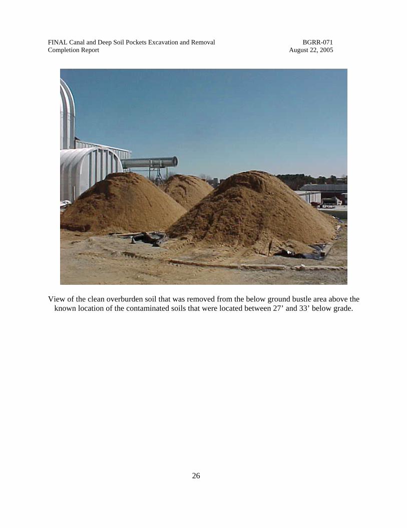
View of the clean overburden soil that was removed from the below ground bustle area above the known location of the contaminated soils that were located between 27’ and 33’ below grade.
FINAL Canal and Deep Soil Pockets Excavation and Removal BGRR-071 Completion Report August 22, 2005
27
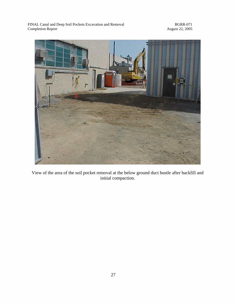
View of the area of the soil pocket removal at the below ground duct bustle after backfill and initial compaction.

FINAL Canal and Deep Soil Pockets Excavation and Removal BGRR-071 Completion Report August 22, 2005
28
View of the 20” thick reinforced concrete wall constructed at the canal removal point. The cut line of the canal structure is located 4’-3” east of Building 701 column 101. Floor and roof drain lines that had been previously cut and abandoned can be seen hanging beneath the floor of the
east intake structure.

FINAL Canal and Deep Soil Pockets Excavation and Removal BGRR-071 Completion Report August 22, 2005
29
A view looking down on the canal excavation and demolition nearing its end. The John Deere excavator at the lower part of this picture is being used to demolish the canal walkway sump into smaller pieces that meet the Envirocare acceptance criteria. At the top of this picture, the forklift is carrying a MHF Waste Liner® to the staging area. Two empty liners can be seen staged and
ready for filling.

FINAL Canal and Deep Soil Pockets Excavation and Removal BGRR-071 Completion Report August 22, 2005
30
Canal excavation and demolition nearing its end. The John Deere excavator is being used to excavate the last remaining concrete debris and soil. At the top of this picture, the forklift is carrying a MHF Waste Liner® to the staging area. Two empty liners can be seen staged and
ready for filling.

FINAL Canal and Deep Soil Pockets Excavation and Removal BGRR-071 Completion Report August 22, 2005
31
View of the canal excavated area after backfill and compaction to the pre-existing grade.

FINAL Canal and Deep Soil Pockets Excavation and Removal BGRR-071 Completion Report August 22, 2005
32
View from the roof of building 701 showing filled waste containers ready for transport to the rail siding for shipment to Envirocare of Utah.

FINAL Canal and Deep Soil Pockets Excavation and Removal BGRR-071 Completion Report August 22, 2005
33
- - View of the canal excavation area after placement of the temporary cap.
-
FINAL Canal and Deep Soil Pockets Excavation and Removal BGRR-071 Completion Report August 22, 2005
34
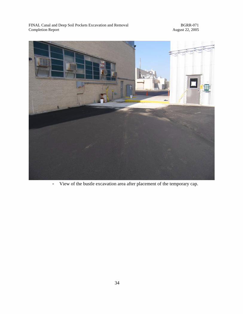
- View of the bustle excavation area after placement of the temporary cap.