bronze and brass ball valves index - … · bronze and brass ball valves index 8100/8111 bv-1 8201...
TRANSCRIPT
BRONZE AND BRASS BALL VALVES INDEX
8100/8111 BV-1
8201 BV-2
8201-15/8211-15 BV-3
8211 BV-4
8271 BV-5
8281 BV-6
8301A/8303A BV-7
8301A/8303A P2 BV-8
8311A/8313A BV-9
8501/8503 BV-10
8501/8503 P2 BV-11
8501E BV-12
8501H/8511H BV-13
8501H/8503H P1 BV-14
8501M BV-15
8503H/8513H BV-16
8511/8513 BV-17
8604/8603 BV-18
8604/8603 P2 BV-19
8614/8613 BV-20
8614-22/8613-22 BV-21
8614-22-G/8613-22-G BV-22
8701/8711 BV-23
8901 BV-24
8911 BV-25
BA-480B BV-26
BA-480BH BV-27
BA-480S BV-28
BA-480SH BV-29
BA-481B BV-30
BA-481S BV-31
BA-490B BV-32
BA-490S BV-33
BA-491B BV-34
BA-491S BV-35
Insulator Handle/MS (16) BV-36 - 38
Options 8201/8211/8901/8911/BA-480B/BA-490B BV-39
Options 8301A/8303A/8501/8503/8604/8603 BV-40
Rev 10/18
The information presented on this sheet is correct at time of publication. Hammond Valve reserves the right to change design and/or materials without notice. For our Installation, Operation and Maintenance Manual and the most current product information go to www.hammondvalve.com. Hammond Valve is a registered trademark of Milwaukee Valve.
State of California Prop 65 WARNING: Cancer and Reproductive Harm. For more information visit www.p65warnings.ca.gov.
BV-1Rev. 8
E - SWT
E - THD
E - SWT
E - THD
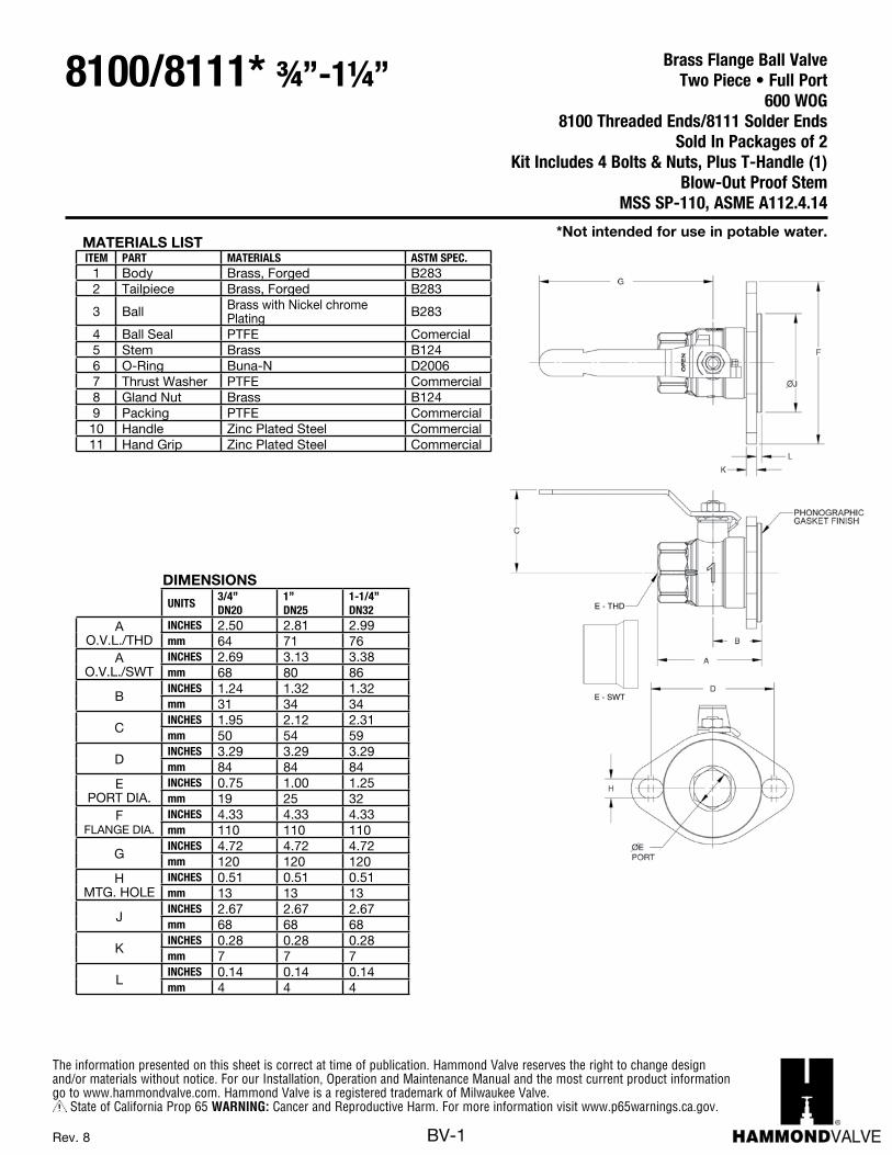
MATERIALS LISTITEM PART MATERIALS ASTM SPEC.
1 Body Brass, Forged B2832 Tailpiece Brass, Forged B283
3 Ball Brass with Nickel chrome Plating B283
4 Ball Seal PTFE Comercial5 Stem Brass B1246 O-Ring Buna-N D20067 Thrust Washer PTFE Commercial8 Gland Nut Brass B1249 Packing PTFE Commercial10 Handle Zinc Plated Steel Commercial11 Hand Grip Zinc Plated Steel Commercial
DIMENSIONS
UNITS3/4”DN20
1”DN25
1-1/4”DN32
A O.V.L./THD
INCHES 2.50 2.81 2.99mm 64 71 76
A O.V.L./SWT
INCHES 2.69 3.13 3.38mm 68 80 86
BINCHES 1.24 1.32 1.32mm 31 34 34
CINCHES 1.95 2.12 2.31mm 50 54 59
DINCHES 3.29 3.29 3.29mm 84 84 84
E PORT DIA.
INCHES 0.75 1.00 1.25mm 19 25 32
F FLANGE DIA.
INCHES 4.33 4.33 4.33mm 110 110 110
GINCHES 4.72 4.72 4.72mm 120 120 120
H MTG. HOLE
INCHES 0.51 0.51 0.51mm 13 13 13
JINCHES 2.67 2.67 2.67mm 68 68 68
KINCHES 0.28 0.28 0.28mm 7 7 7
LINCHES 0.14 0.14 0.14mm 4 4 4
*Not intended for use in potable water.
Brass Flange Ball ValveTwo Piece • Full Port
600 WOG8100 Threaded Ends/8111 Solder Ends
Sold In Packages of 2Kit Includes 4 Bolts & Nuts, Plus T-Handle (1)
Blow-Out Proof StemMSS SP-110, ASME A112.4.14
8100/8111* ¾”-1¼”
The information presented on this sheet is correct at time of publication. Hammond Valve reserves the right to change design and/or materials without notice. For our Installation, Operation and Maintenance Manual and the most current product information go to www.hammondvalve.com. Hammond Valve is a registered trademark of Milwaukee Valve.
State of California Prop 65 WARNING: Cancer and Reproductive Harm. For more information visit www.p65warnings.ca.gov.
BV-2Rev. 8
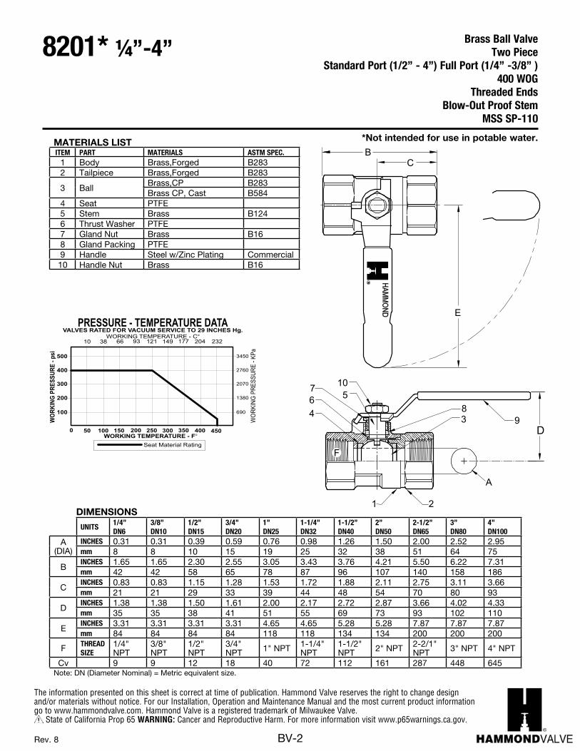
MATERIALS LISTITEM PART MATERIALS ASTM SPEC.
1 Body Brass,Forged B2832 Tailpiece Brass,Forged B283
3 BallBrass,CP B283Brass CP, Cast B584
4 Seat PTFE5 Stem Brass B1246 Thrust Washer PTFE7 Gland Nut Brass B168 Gland Packing PTFE9 Handle Steel w/Zinc Plating Commercial
10 Handle Nut Brass B16
DIMENSIONS
UNITS1/4”DN6
3/8”DN10
1/2”DN15
3/4”DN20
1”DN25
1-1/4”DN32
1-1/2”DN40
2”DN50
2-1/2”DN65
3”DN80
4”DN100
A (DIA)
INCHES 0.31 0.31 0.39 0.59 0.76 0.98 1.26 1.50 2.00 2.52 2.95mm 8 8 10 15 19 25 32 38 51 64 75
BINCHES 1.65 1.65 2.30 2.55 3.05 3.43 3.76 4.21 5.50 6.22 7.31mm 42 42 58 65 78 87 96 107 140 158 186
CINCHES 0.83 0.83 1.15 1.28 1.53 1.72 1.88 2.11 2.75 3.11 3.66mm 21 21 29 33 39 44 48 54 70 80 93
DINCHES 1.38 1.38 1.50 1.61 2.00 2.17 2.72 2.87 3.66 4.02 4.33mm 35 35 38 41 51 55 69 73 93 102 110
EINCHES 3.31 3.31 3.31 3.31 4.65 4.65 5.28 5.28 7.87 7.87 7.87mm 84 84 84 84 118 118 134 134 200 200 200
F THREADSIZE
1/4" NPT
3/8" NPT
1/2" NPT
3/4" NPT 1" NPT 1-1/4"
NPT1-1/2" NPT 2" NPT 2-2/1"
NPT 3" NPT 4" NPT
Cv 9 9 12 18 40 72 112 161 287 448 645Note: DN (Diameter Nominal) = Metric equivalent size.
690
1380
2070
2760
3450
GNIKROW
ERUSSERPp-
si
WORKING TEMPERATURE - F
VALVES RATED FOR VACUUM SERVICE TO 29 INCHES Hg.PRESSURE - TEMPERATURE DATA
100
200
300
400
500
0 50 150 200 250 300 350 400 450100
GNIKRO
WERUSSERP
-aPK
10WORKING TEMPERATURE - C
66 121 149 177 20438 93
Seat Material Rating
232
1
4 3
2
58
7 10
6
D
A
F
9
BC
ER
LIM
WE
EK
UA
VL
AE
VP
MO
CY
NA
R
004
GO
W05
1P
WS
*Not intended for use in potable water.
Brass Ball ValveTwo Piece
Standard Port (1/2” - 4”) Full Port (1/4” -3/8” )400 WOG
Threaded EndsBlow-Out Proof Stem
MSS SP-110
8201* ¼”-4”
The information presented on this sheet is correct at time of publication. Hammond Valve reserves the right to change design and/or materials without notice. For our Installation, Operation and Maintenance Manual and the most current product information go to www.hammondvalve.com. Hammond Valve is a registered trademark of Milwaukee Valve.
State of California Prop 65 WARNING: Cancer and Reproductive Harm. For more information visit www.p65warnings.ca.gov.
BV-3Rev. 11
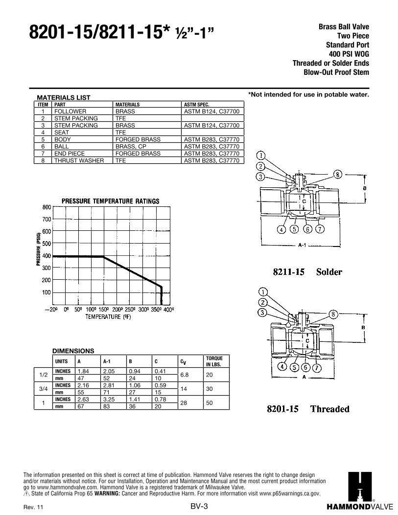
MATERIALS LISTITEM PART MATERIALS ASTM SPEC.
1 FOLLOWER BRASS ASTM B124, C377002 STEM PACKING TFE3 STEM PACKING BRASS ASTM B124, C377004 SEAT TFE5 BODY FORGED BRASS ASTM B283, C377706 BALL BRASS, CP ASTM B283, C377707 END PIECE FORGED BRASS ASTM B283, C377708 THRUST WASHER TFE ASTM B283, C37770
DIMENSIONS
UNITS A A-1 B C CVTORQUEIN LBS.
1/2INCHES 1.84 2.05 0.94 0.41
6.8 20mm 47 52 24 10
3/4INCHES 2.16 2.81 1.06 0.59
14 30mm 55 71 27 15
1INCHES 2.63 3.25 1.41 0.78
28 50mm 67 83 36 20
*Not intended for use in potable water.
Brass Ball ValveTwo Piece
Standard Port 400 PSI WOG
Threaded or Solder EndsBlow-Out Proof Stem
8201-15/8211-15* ½”-1”
The information presented on this sheet is correct at time of publication. Hammond Valve reserves the right to change design and/or materials without notice. For our Installation, Operation and Maintenance Manual and the most current product information go to www.hammondvalve.com. Hammond Valve is a registered trademark of Milwaukee Valve.
State of California Prop 65 WARNING: Cancer and Reproductive Harm. For more information visit www.p65warnings.ca.gov.
BV-4Rev. 10
690
1380
2070
2760
3450
p-ERUSSERP
GNIKROW
is
WORKING TEMPERATURE - F
100
200
300
400
500
0 50 150 200 250 300 350 400 450100
aPK-ERUSSERP
GNIKRO
W
Body / Seat Material Rating
VALVES RATED FOR VACUUM SERVICE TO 29 INCHES Hg.PRESSURE - TEMPERATURE DATA
10WORKING TEMPERATURE - C
66 121 149 177 20438 93 232
BC
1
43
2
5
8
7 10
6
D
E
A
F
9
R
PM
OC
EVL
AVE
EK
UA
WLI
MY
NA
R
004
GO
W05
1P
WS
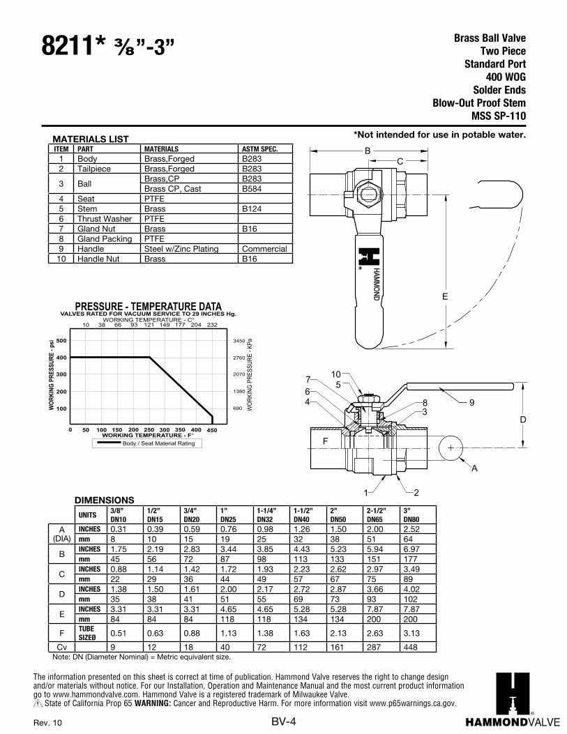
MATERIALS LISTITEM PART MATERIALS ASTM SPEC.
1 Body Brass,Forged B2832 Tailpiece Brass,Forged B283
3 BallBrass,CP B283Brass CP, Cast B584
4 Seat PTFE5 Stem Brass B1246 Thrust Washer PTFE7 Gland Nut Brass B168 Gland Packing PTFE9 Handle Steel w/Zinc Plating Commercial
10 Handle Nut Brass B16
DIMENSIONS
UNITS3/8”DN10
1/2”DN15
3/4”DN20
1”DN25
1-1/4”DN32
1-1/2”DN40
2”DN50
2-1/2”DN65
3”DN80
A (DIA)
INCHES 0.31 0.39 0.59 0.76 0.98 1.26 1.50 2.00 2.52mm 8 10 15 19 25 32 38 51 64
BINCHES 1.75 2.19 2.83 3.44 3.85 4.43 5.23 5.94 6.97mm 45 56 72 87 98 113 133 151 177
CINCHES 0.88 1.14 1.42 1.72 1.93 2.23 2.62 2.97 3.49mm 22 29 36 44 49 57 67 75 89
DINCHES 1.38 1.50 1.61 2.00 2.17 2.72 2.87 3.66 4.02mm 35 38 41 51 55 69 73 93 102
EINCHES 3.31 3.31 3.31 4.65 4.65 5.28 5.28 7.87 7.87mm 84 84 84 118 118 134 134 200 200
F TUBESIZEØ 0.51 0.63 0.88 1.13 1.38 1.63 2.13 2.63 3.13
Cv 9 12 18 40 72 112 161 287 448Note: DN (Diameter Nominal) = Metric equivalent size.
*Not intended for use in potable water.
Brass Ball ValveTwo Piece
Standard Port400 WOG
Solder EndsBlow-Out Proof Stem
MSS SP-110
8211* ⅜”-3”
The information presented on this sheet is correct at time of publication. Hammond Valve reserves the right to change design and/or materials without notice. For our Installation, Operation and Maintenance Manual and the most current product information go to www.hammondvalve.com. Hammond Valve is a registered trademark of Milwaukee Valve.
State of California Prop 65 WARNING: Cancer and Reproductive Harm. For more information visit www.p65warnings.ca.gov.
BV-5Rev. 10
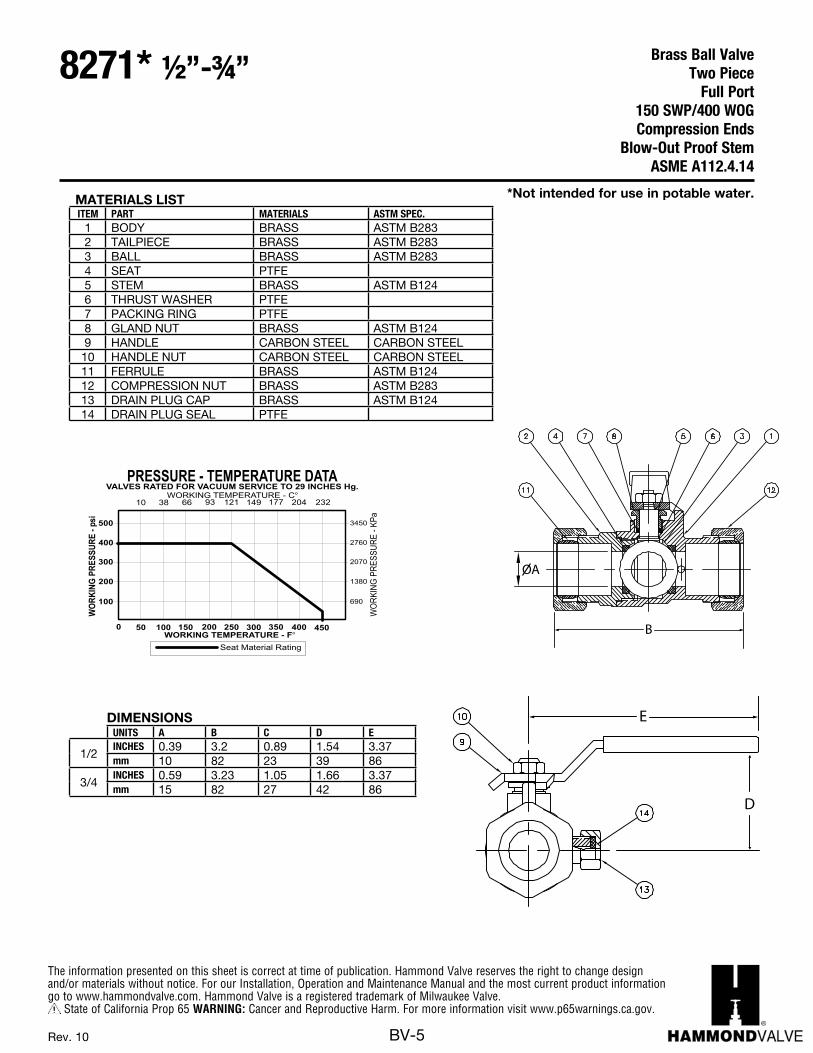
MATERIALS LISTITEM PART MATERIALS ASTM SPEC.
1 BODY BRASS ASTM B2832 TAILPIECE BRASS ASTM B2833 BALL BRASS ASTM B2834 SEAT PTFE5 STEM BRASS ASTM B1246 THRUST WASHER PTFE7 PACKING RING PTFE8 GLAND NUT BRASS ASTM B1249 HANDLE CARBON STEEL CARBON STEEL
10 HANDLE NUT CARBON STEEL CARBON STEEL11 FERRULE BRASS ASTM B12412 COMPRESSION NUT BRASS ASTM B28313 DRAIN PLUG CAP BRASS ASTM B12414 DRAIN PLUG SEAL PTFE
*Not intended for use in potable water.
Brass Ball ValveTwo Piece
Full Port150 SWP/400 WOGCompression Ends
Blow-Out Proof StemASME A112.4.14
8271* ½”-¾”
DIMENSIONSUNITS A B C D E
1/2INCHES 0.39 3.2 0.89 1.54 3.37mm 10 82 23 39 86
3/4INCHES 0.59 3.23 1.05 1.66 3.37mm 15 82 27 42 86
E
D
B
OA
E
D
B
OA
1/4" 3/8" 1/2" 3/4" 1" 1-1/4" 1-1/2" 2" 2-1/2" 3" 4"DN6 DN10 DN15 DN20 DN25 DN32 DN40 DN50 DN65 DN80 DN100
IN C H ES 0.31 0.31 0.39 0.59 0.79 1.00 1.26 1.50 2.00 2.52 2.95mm 7.9 7.9 9.9 15.0 20.1 25.4 32.0 38.1 50.8 64.0 74.9IN C H ES 1.65 1.65 2.30 2.55 3.05 3.43 3.76 4.21 5.50 6.22 7.31mm 41.9 41.9 58.4 64.8 77.5 87.1 95.5 106.9 139.8 158.0 185.5IN C H ES 0.83 0.83 1.15 1.28 1.53 1.72 1.88 2.11 2.75 3.11 3.66mm 21.1 21.1 5.6 32.5 38.9 43.7 47.8 53.6 69.9 79.0 93.0IN C H ES 1.38 1.38 1.50 1.61 2.00 2.17 2.72 2.87 3.66 4.02 4.33mm 35.1 35.1 38.1 40.9 50.8 55.1 69.1 72.9 93.0 102.1 110.0IN C H ES 3.31 3.31 3.31 3.31 4.65 4.65 5.28 5.28 7.87 7.87 7.87mm 84.1 84.1 84.1 84.1 118.1 118.1 134.1 134.1 199.9 199.9 199.9T H R EA DSIZ E 1/4" NPT 3/8" NPT 1/2" NPT 3/4" NPT 1" NPT 1-1/4" NPT 1-1/2" NPT 2" NPT 2-1/2" NPT 3" NPT 4" NPT
9 9 12 18 40 72 112 161 287 448 645Note: DN (Diameter Nominal) = Metric equivalent size.
UNITS
E
F
Cv
A (DIA)
B
C
D
8201 14"/ -4"
DIMENSIONS
1
4 3
2
58
7 10
6
D
A
F
9
FORGED BRASS BALL VALVETWO PIECE, STANDARD PORT (1/2”-4”) FULL-PORT 1/4”-3/8”)400 PSIG WOGTHREADED ENDSBLOW-OUT PROOF STEM
ASME A 112.4.14
690
1380
2070
2760
3450
GNIKROW
ERUSSERPp-
si
WORKING TEMPERATURE - F
VALVES RATED FOR VACUUM SERVICE TO 29 INCHES Hg.PRESSURE - TEMPERATURE DATA
100
200
300
400
500
0 50 150 200 250 300 350 400 450100
GNIKRO
WERUSSERP
-aPK
10WORKING TEMPERATURE - C
66 121 149 177 20438 93
Seat Material Rating
232
BC
E
HAMM
OND
R
The information presented on this sheet is correct at time of publication. Hammond Valve reserves the right to change design and/or materials without notice. For our Installation, Operation and Maintenance Manual and the most current product information go to www.hammondvalve.com. Hammond Valve is a registered trademark of Milwaukee Valve.
State of California Prop 65 WARNING: Cancer and Reproductive Harm. For more information visit www.p65warnings.ca.gov.
BV-6Rev. 11
D
C
B
OA
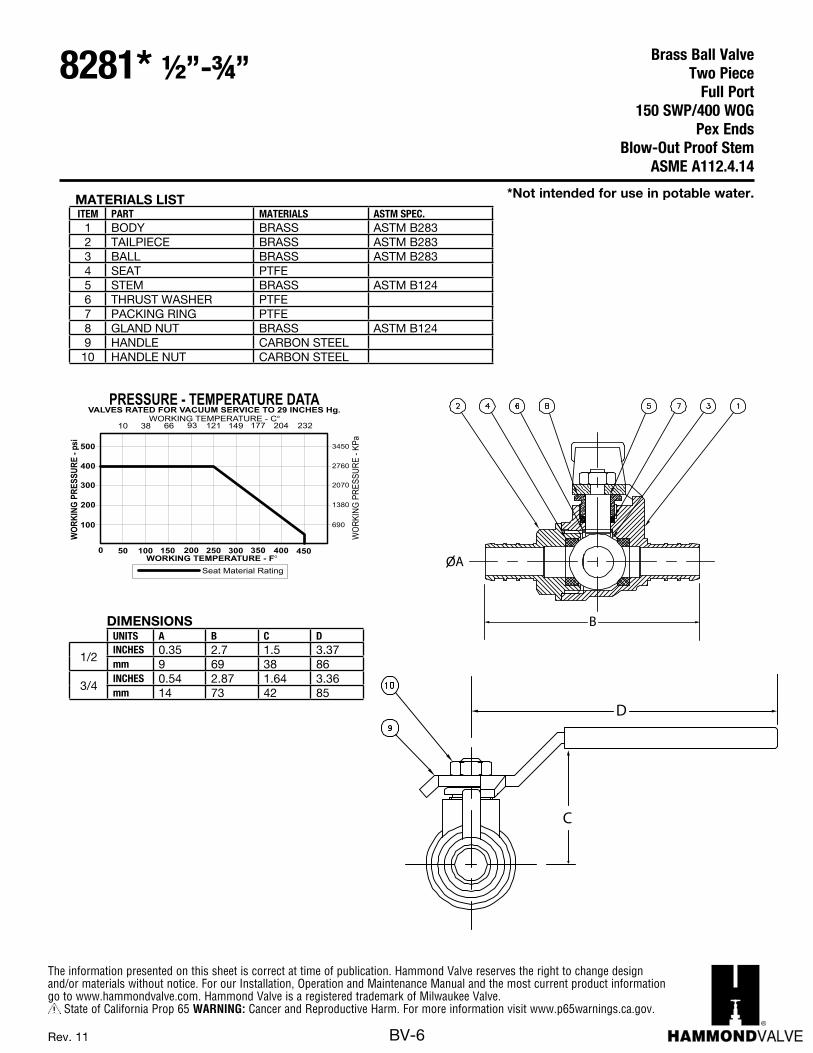
MATERIALS LISTITEM PART MATERIALS ASTM SPEC.
1 BODY BRASS ASTM B2832 TAILPIECE BRASS ASTM B2833 BALL BRASS ASTM B2834 SEAT PTFE5 STEM BRASS ASTM B1246 THRUST WASHER PTFE7 PACKING RING PTFE8 GLAND NUT BRASS ASTM B1249 HANDLE CARBON STEEL
10 HANDLE NUT CARBON STEEL
*Not intended for use in potable water.
Brass Ball ValveTwo Piece
Full Port150 SWP/400 WOG
Pex EndsBlow-Out Proof Stem
ASME A112.4.14
8281* ½”-¾”
DIMENSIONSUNITS A B C D
1/2INCHES 0.35 2.7 1.5 3.37mm 9 69 38 86
3/4INCHES 0.54 2.87 1.64 3.36mm 14 73 42 85
D
C
B
OA
1/4" 3/8" 1/2" 3/4" 1" 1-1/4" 1-1/2" 2" 2-1/2" 3" 4"DN6 DN10 DN15 DN20 DN25 DN32 DN40 DN50 DN65 DN80 DN100
IN C H ES 0.31 0.31 0.39 0.59 0.79 1.00 1.26 1.50 2.00 2.52 2.95mm 7.9 7.9 9.9 15.0 20.1 25.4 32.0 38.1 50.8 64.0 74.9IN C H ES 1.65 1.65 2.30 2.55 3.05 3.43 3.76 4.21 5.50 6.22 7.31mm 41.9 41.9 58.4 64.8 77.5 87.1 95.5 106.9 139.8 158.0 185.5IN C H ES 0.83 0.83 1.15 1.28 1.53 1.72 1.88 2.11 2.75 3.11 3.66mm 21.1 21.1 5.6 32.5 38.9 43.7 47.8 53.6 69.9 79.0 93.0IN C H ES 1.38 1.38 1.50 1.61 2.00 2.17 2.72 2.87 3.66 4.02 4.33mm 35.1 35.1 38.1 40.9 50.8 55.1 69.1 72.9 93.0 102.1 110.0IN C H ES 3.31 3.31 3.31 3.31 4.65 4.65 5.28 5.28 7.87 7.87 7.87mm 84.1 84.1 84.1 84.1 118.1 118.1 134.1 134.1 199.9 199.9 199.9T H R EA DSIZ E 1/4" NPT 3/8" NPT 1/2" NPT 3/4" NPT 1" NPT 1-1/4" NPT 1-1/2" NPT 2" NPT 2-1/2" NPT 3" NPT 4" NPT
9 9 12 18 40 72 112 161 287 448 645Note: DN (Diameter Nominal) = Metric equivalent size.
UNITS
E
F
Cv
A (DIA)
B
C
D
8201 14"/ -4"
DIMENSIONS
1
4 3
2
58
7 10
6
D
A
F
9
FORGED BRASS BALL VALVETWO PIECE, STANDARD PORT (1/2”-4”) FULL-PORT 1/4”-3/8”)400 PSIG WOGTHREADED ENDSBLOW-OUT PROOF STEM
ASME A 112.4.14
690
1380
2070
2760
3450
GNIKROW
ERUSSERPp-
si
WORKING TEMPERATURE - F
VALVES RATED FOR VACUUM SERVICE TO 29 INCHES Hg.PRESSURE - TEMPERATURE DATA
100
200
300
400
500
0 50 150 200 250 300 350 400 450100
GNIKRO
WERUSSERP
-aPK
10WORKING TEMPERATURE - C
66 121 149 177 20438 93
Seat Material Rating
232
BC
E
HAMM
OND
R
The information presented on this sheet is correct at time of publication. Hammond Valve reserves the right to change design and/or materials without notice. For our Installation, Operation and Maintenance Manual and the most current product information go to www.hammondvalve.com. Hammond Valve is a registered trademark of Milwaukee Valve.
State of California Prop 65 WARNING: Cancer and Reproductive Harm. For more information visit www.p65warnings.ca.gov.
BV-7Rev. 9
690
1380
2070
2760
4140
3450
4830
WOR
KING
PRES
SURE
sip-
100
200
300
400
600
500
700
Saturated Steam
WORKING TEMPERATURE - F0 50 150 200 250 300 350 400 450100
GNIKRO
WERUSSERP
-aPK
10WORKING TEMPERATURE - C
66 121 149 177 20438
Seat Material Rating
93
VALVES RATED FOR VACUUM SERVICE TO 29 INCHES Hg.PRESSURE - TEMPERATURE DATA
AD
E
2
34
567
8
910
11
BC
1
F
O P E N600W
OG
150S
WP
MILW
AU
KE
EVA
LVE
CO
MPA
NY,IN
CR
DIMENSIONSUNITS
1/4”DN10
3/8”DN10
1/2”DN15
3/4”DN20
1”DN25
1-1/4”DN32
1-1/2”DN40
2”DN50
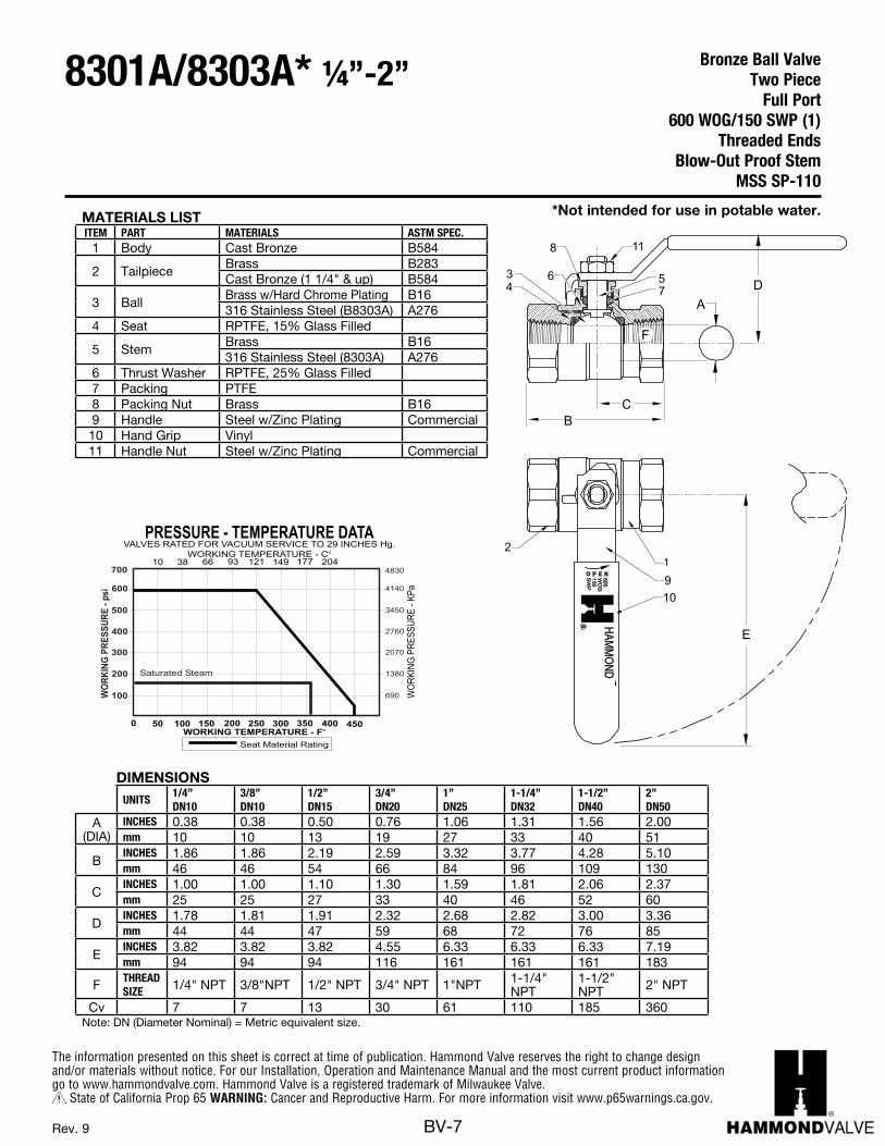
A (DIA)
INCHES 0.38 0.38 0.50 0.76 1.06 1.31 1.56 2.00mm 10 10 13 19 27 33 40 51
BINCHES 1.86 1.86 2.19 2.59 3.32 3.77 4.28 5.10mm 46 46 54 66 84 96 109 130
CINCHES 1.00 1.00 1.10 1.30 1.59 1.81 2.06 2.37mm 25 25 27 33 40 46 52 60
DINCHES 1.78 1.81 1.91 2.32 2.68 2.82 3.00 3.36mm 44 44 47 59 68 72 76 85
EINCHES 3.82 3.82 3.82 4.55 6.33 6.33 6.33 7.19mm 94 94 94 116 161 161 161 183
F THREADSIZE 1/4" NPT 3/8"NPT 1/2" NPT 3/4" NPT 1"NPT 1-1/4"
NPT1-1/2" NPT 2" NPT
Cv 7 7 13 30 61 110 185 360Note: DN (Diameter Nominal) = Metric equivalent size.
MATERIALS LISTITEM PART MATERIALS ASTM SPEC.
1 Body Cast Bronze B584
2 TailpieceBrass B283Cast Bronze (1 1/4" & up) B584
3 BallBrass w/Hard Chrome Plating B16316 Stainless Steel (B8303A) A276
4 Seat RPTFE, 15% Glass Filled
5 StemBrass B16316 Stainless Steel (8303A) A276
6 Thrust Washer RPTFE, 25% Glass Filled7 Packing PTFE8 Packing Nut Brass B169 Handle Steel w/Zinc Plating Commercial10 Hand Grip Vinyl11 Handle Nut Steel w/Zinc Plating Commercial
*Not intended for use in potable water.
Bronze Ball ValveTwo Piece
Full Port 600 WOG/150 SWP (1)
Threaded EndsBlow-Out Proof Stem
MSS SP-110
8301A/8303A* ¼”-2”
The information presented on this sheet is correct at time of publication. Hammond Valve reserves the right to change design and/or materials without notice. For our Installation, Operation and Maintenance Manual and the most current product information go to www.hammondvalve.com. Hammond Valve is a registered trademark of Milwaukee Valve.
State of California Prop 65 WARNING: Cancer and Reproductive Harm. For more information visit www.p65warnings.ca.gov.
BV-8Rev. 5
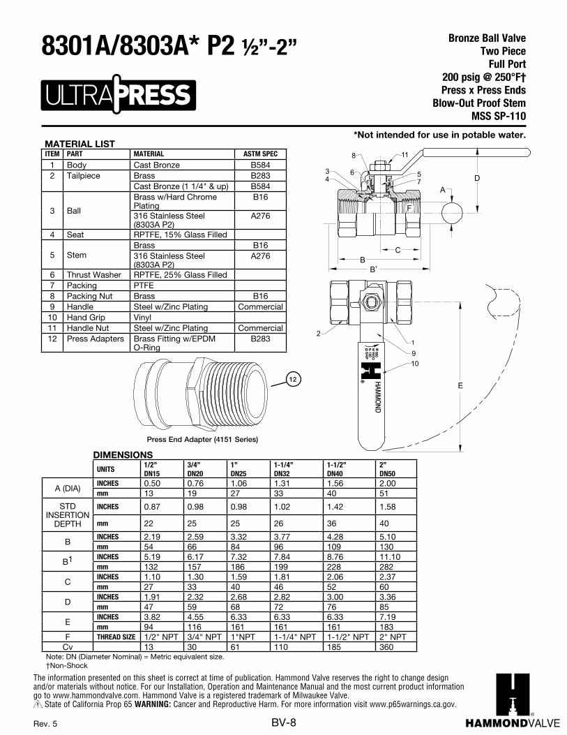
MATERIAL LISTITEM PART MATERIAL ASTM SPEC
1 Body Cast Bronze B5842 Tailpiece Brass B283
Cast Bronze (1 1/4" & up) B584
3 Ball
Brass w/Hard Chrome Plating
B16
316 Stainless Steel (8303A P2)
A276
4 Seat RPTFE, 15% Glass Filled
5 StemBrass B16316 Stainless Steel (8303A P2)
A276
6 Thrust Washer RPTFE, 25% Glass Filled7 Packing PTFE8 Packing Nut Brass B169 Handle Steel w/Zinc Plating Commercial10 Hand Grip Vinyl11 Handle Nut Steel w/Zinc Plating Commercial12 Press Adapters Brass Fitting w/EPDM
O-RingB283
Press End Adapter (4151 Series)
12
*Not intended for use in potable water.
Bronze Ball ValveTwo Piece
Full Port 200 psig @ 250°F†Press x Press Ends
Blow-Out Proof StemMSS SP-110
8301A/8303A* P2 ½”-2”
/ 2BRONZE BALL VALVETWO-PIECE, FULL-PORT200 PSIG @ 250°FPRESS ENDSBLOW-OUT PROOF STEM
AD
E
2
34
567
8
910
11
DIMENSIONS
BC
BA-400 400S* P2 12 -" "
1
F
MSS SP-110
O P E N600W
OG
150S
WP
MILW
AU
KE
EVA
LVE
CO
MPA
NY,IN
CR
(1) For steam service specify see BA400S3
690
1380
2070
2760
4140
3450
4830
GNIKROW
ERUSSERP- p
is
WORKING TEMPERATURE - F
100
200
300
400
600
500
700
0 50 150 200 250 300 350 400 450100
GNIKRO
WERUSSERP
-aPK
10WORKING TEMPERATURE - C
66 121 149 177 20438
Seat Material Rating
93
VALVES RATED FOR VACUUM SERVICE TO 29 INCHES Hg.PRESSURE - TEMPERATURE DATA
BRONZE BALL VALVETWO-PIECE, FULL-PORT600 PSIG WOG / 150 PSIG SWP (1)THREADED ENDS
AD
E
2
34
567
8
910
11
DIMENSIONS
BC
BA-400 400S 14 -"/ 2 "
1
F
FED. SPEC. WW-V-35C, II, BZ, 3MSS SP-110
O P E N600W
OG
MILW
AU
KE
EVA
LVE
CO
MPA
NY,IN
CR
(1) Milwaukee Valve Company recommends the use of
(2) Ball and stem are stainless for 400S.(3) For steam service, specify stainless trim and multi-fil
seats, maximum stem pressure 150.
stainless steel ball and stem for steam applications.Please consult factory for more information.
690
1380
2070
2760
4140
3450
4830
GNIKROW
ERUSSERP- p
is
WORKING TEMPERATURE - F
100
200
300
400
600
500
700
0 50 150 200 250 300 350 400 450100
GNIKRO
WERUSSERP
-aPK
10WORKING TEMPERATURE - C
66 121 149 177 20438
Seat Material Rating
93
SaturatedSteam
VALVES RATED FOR VACUUM SERVICE TO 29 INCHES Hg.PRESSURE - TEMPERATURE DATA
B1
DIMENSIONSUNITS
1/2”DN15
3/4”DN20
1”DN25
1-1/4”DN32
1-1/2”DN40
2”DN50
A (DIA)INCHES 0.50 0.76 1.06 1.31 1.56 2.00mm 13 19 27 33 40 51
STD INSERTION
DEPTH
INCHES 0.87 0.98 0.98 1.02 1.42 1.58
mm 22 25 25 26 36 40
BINCHES 2.19 2.59 3.32 3.77 4.28 5.10mm 54 66 84 96 109 130
B1 INCHES 5.19 6.17 7.32 7.84 8.76 11.10mm 132 157 186 199 228 282
CINCHES 1.10 1.30 1.59 1.81 2.06 2.37mm 27 33 40 46 52 60
DINCHES 1.91 2.32 2.68 2.82 3.00 3.36mm 47 59 68 72 76 85
EINCHES 3.82 4.55 6.33 6.33 6.33 7.19mm 94 116 161 161 161 183
F THREAD SIZE 1/2" NPT 3/4" NPT 1"NPT 1-1/4" NPT 1-1/2" NPT 2" NPTCv 13 30 61 110 185 360
Note: DN (Diameter Nominal) = Metric equivalent size. †Non-Shock
The information presented on this sheet is correct at time of publication. Hammond Valve reserves the right to change design and/or materials without notice. For our Installation, Operation and Maintenance Manual and the most current product information go to www.hammondvalve.com. Hammond Valve is a registered trademark of Milwaukee Valve.
State of California Prop 65 WARNING: Cancer and Reproductive Harm. For more information visit www.p65warnings.ca.gov.
BV-9Rev. 10
BRONZE BALL VALVETWO-PIECE, FULL-PORT600 PSIG WOGSOLDER ENDSBLOW-OUT PROOF STEM
DIMENSIONS
BA-450 38 -"/ 2 "MSS SP-110
B
A
F
D
C
E
2
910
11
1
57
34
6
8
O P E N600W
OG
150S
WP
MILW
AU
KE
EVA
LVE
CO
MPA
NY,IN
CR
(1) Ball and stem are stainless for 450S.
VALVES RATED FOR VACUUM SERVICE TO 29 INCHES Hg.PRESSURE - TEMPERATURE DATA
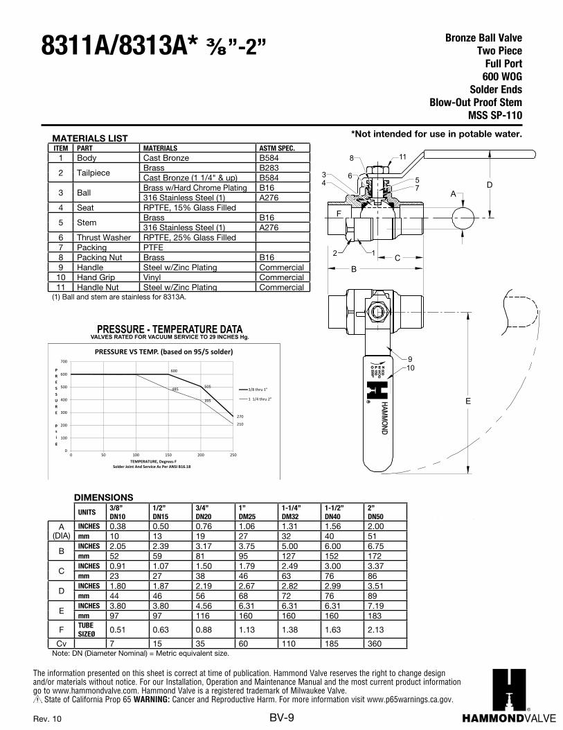
MATERIALS LISTITEM PART MATERIALS ASTM SPEC.
1 Body Cast Bronze B584
2 TailpieceBrass B283Cast Bronze (1 1/4" & up) B584
3 BallBrass w/Hard Chrome Plating B16316 Stainless Steel (1) A276
4 Seat RPTFE, 15% Glass Filled
5 StemBrass B16316 Stainless Steel (1) A276
6 Thrust Washer RPTFE, 25% Glass Filled7 Packing PTFE8 Packing Nut Brass B169 Handle Steel w/Zinc Plating Commercial10 Hand Grip Vinyl Commercial11 Handle Nut Steel w/Zinc Plating Commercial
(1) Ball and stem are stainless for 8313A.
DIMENSIONS
UNITS3/8”DN10
1/2”DN15
3/4”DN20
1”DM25
1-1/4”DM32
1-1/2”DN40
2”DN50
A (DIA)
INCHES 0.38 0.50 0.76 1.06 1.31 1.56 2.00mm 10 13 19 27 32 40 51
BINCHES 2.05 2.39 3.17 3.75 5.00 6.00 6.75mm 52 59 81 95 127 152 172
CINCHES 0.91 1.07 1.50 1.79 2.49 3.00 3.37mm 23 27 38 46 63 76 86
DINCHES 1.80 1.87 2.19 2.67 2.82 2.99 3.51mm 44 46 56 68 72 76 89
EINCHES 3.80 3.80 4.56 6.31 6.31 6.31 7.19mm 97 97 116 160 160 160 183
F TUBE SIZEØ 0.51 0.63 0.88 1.13 1.38 1.63 2.13
Cv 7 15 35 60 110 185 360Note: DN (Diameter Nominal) = Metric equivalent size.
BRONZE BALL VALVETWO-PIECE, FULL-PORT600 PSIG WOGSOLDER ENDSBLOW-OUT PROOF STEM
DIMENSIONS
BA-450 38 -"/ 2 "MSS SP-110
B
A
F
D
C
E
2
910
11
1
57
34
6
8
O P E N600W
OG
150S
WP
MILW
AU
KE
EVA
LVE
CO
MPA
NY,IN
CR
(1) Ball and stem are stainless for 450S.
VALVES RATED FOR VACUUM SERVICE TO 29 INCHES Hg.PRESSURE - TEMPERATURE DATA
505
270
485
395
210
0
100
200
300
400
500
600
700
0 50 100 150 200 250
PRESSURE
psig
PRESSURE VS TEMP. (based on 95/5 solder)
3/8 thru 1"
1 1/4 thru 2"
600
TEMPERATURE, Degrees FSolder Joint And Service As Per ANSI B16.18
*Not intended for use in potable water.
Bronze Ball ValveTwo Piece
Full Port 600 WOG
Solder EndsBlow-Out Proof Stem
MSS SP-110
8311A/8313A* ⅜”-2”

The information presented on this sheet is correct at time of publication. Hammond Valve reserves the right to change design and/or materials without notice. For our Installation, Operation and Maintenance Manual and the most current product information go to www.hammondvalve.com. Hammond Valve is a registered trademark of Milwaukee Valve.
State of California Prop 65 WARNING: Cancer and Reproductive Harm. For more information visit www.p65warnings.ca.gov.
BV-10Rev. 11
*Not intended for use in potable water.MATERIALS LISTITEM PART MATERIALS ASTM SPEC.
1 Body Cast Bronze B584
2 TailpieceBrass B283Cast Bronze (1 1/4" & up) B584
3 BallBrass w/Hard Chrome Plating B16
316 Stainless Steel (2) A2764 Seat RPTFE, 15% Glass Filled
5 StemBrass B16316 Stainless Steel (2) A276
6 Thrust Washer RPTFE, 25% Glass Filled7 Packing PTFE8 Packing Nut Brass B169 Handle Steel w/Zinc Plating Commercial10 Hand Grip Vinyl11 Handle Nut Steel w/Zinc Plating Commercial
(1) Hammond Valve recommends the use of Stainless steel ball and stem for steam applications. Please consult factory for more information. (2) Stem is stainless for 8503 and 2-1/2”–3” 8501
B
AD
C
E
34
567
8 11
F
2 1
910O P E N600
WO
G150S
WP
MILW
AU
KE
EVA
LVE
CO
MPA
NY, IN
CR
690
1380
2070
2760
4140
3450
4830
GNIKROW
ERUSSERP- p
is
WORKING TEMPERATURE - F
PRESSURE - TEMPERATURE DATA
100
200
300
400
600
500
700
0 50 150 200 250 300 350 400 450100
GNIKRO
WERUSSERP
-aPK
10WORKING TEMPERATURE - C
66 121 149 177 20438
Seat Material Rating
93
Saturated Steam
VALVES RATED FOR VACUUM SERVICE TO 29 INCHES Hg.
232
DIMENSIONS
UNITS1/4”DN6
3/8”DN10
1/2”DN15
3/4”DN20
1”DN25
1-1/4”DN32
1-1/2”DN40
2”DN50
2-1/2”DN65
3”DN80
A (DIA)
INCHES 0.38 0.38 0.50 0.76 0.88 1.06 1.31 1.56 2.00 2.31mm 10 10 13 19 22 27 33 40 51 59
BINCHES 1.86 1.86 2.19 2.64 3.17 3.50 3.96 4.30 5.56 6.20mm 46 46 54 65 78 86 97 105 136 152
CINCHES 1.00 1.00 1.10 1.30 1.58 1.74 1.97 2.15 2.79 3.10mm 25 25 27 32 39 43 48 53 68 76
DINCHES 1.78 1.81 1.91 2.08 2.25 2.66 2.84 3.00 3.47 3.90mm 44 44 47 51 55 65 70 74 85 96
EINCHES 3.81 3.81 3.81 4.56 4.56 6.31 6.31 7.19 7.19 7.19mm 93 93 93 112 112 155 155 176 176 176
F THREADSIZE 1/4" NPT 3/8"NPT 1/2" NPT 3/4" NPT 1"NPT 1-1/4"
NPT1-1/2" NPT 2" NPT 2-1/2"
NPT 3" NPT
Cv 7 7 13 30 38 61 87 121 228 305Note: DN (Diameter Nominal) = Metric equivalent size.
Bronze Ball ValveTwo Piece
Standard Port (1”-3”) Full Port (1/4”-3/4”)600 WOG/150 SWP (1)
Threaded EndsBlow-Out Proof Stem
MSS SP-110
8501/8503* ¼”-3”
The information presented on this sheet is correct at time of publication. Hammond Valve reserves the right to change design and/or materials without notice. For our Installation, Operation and Maintenance Manual and the most current product information go to www.hammondvalve.com. Hammond Valve is a registered trademark of Milwaukee Valve.
State of California Prop 65 WARNING: Cancer and Reproductive Harm. For more information visit www.p65warnings.ca.gov.
BV-11
E
2
9 101
OP
EN 600
WOG150SWP MILWAUKEE VALVE COMPANY, INC
R
Rev. 5
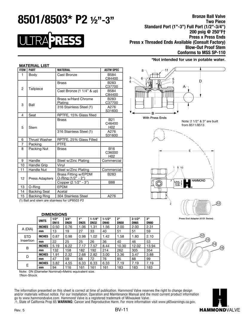
*Not intended for use in potable water.
Bronze Ball ValveTwo Piece
Standard Port (1”-3”) Full Port (1/2”-3/4”)200 psig @ 250°F†Press x Press Ends
Press x Threaded Ends Available (Consult Factory)Blow-Out Proof Stem
Conforms to MSS SP-110
8501/8503* P2 ½”-3”
MATERIAL LISTITEM PART MATERIAL ASTM SPEC
1 Body Cast Bronze B584 C84400
2 Tailpiece
Brass B283C37700
Cast Bronze (1 1/4” & up) B584C84400
3 Ball
Brass w/Hard Chrome Plating
B283 C37700
316 Stainless Steel (1) A276 S31600
4 Seat RPTFE, 15% Glass filled
5 Stem
Brass B21 C46400
H02316 Stainless Steel (1) A276
S316006 Thrust Washer RPTFE, 25% Glass Filled7 Packing PTFE8 Packing Nut Brass B16
C36000H02
9 Handle Steel w/Zinc Plating Commercial10 Handle Grip Vinyl11 Handle Nut Steel w/Zinc Plating Commercial
12 Press AdaptersBrass Fitting w/EPDM O-Ring (1/2" - 2")
B283
Copper (2 1/2” - 3”) B8813 O-Ring EPDM14 Backing Seal Acetal15 Backing Ring 304 Stainless Steel A276
(1) Ball and stem are stainless for UP8503 P2
/ 2BRONZE BALL VALVETWO-PIECE, FULL-PORT (1/4”-3/4”) STANDARD PORT (1”-2”)200 PSIG @ 250°FPRESS ENDSBLOW-OUT PROOF STEM
AD
E
2
34
567
8
910
11
DIMENSIONS
BA-100 400S* P2 12 -" "
1
MSS SP-110
O P E N600W
OG
150S
WP
MILW
AU
KE
EVA
LVE
CO
MPA
NY,IN
CR
(1) For steam service specify see BA400S3
690
1380
2070
2760
4140
3450
4830
GNIKROW
ERUSSERP- p
is
WORKING TEMPERATURE - F
100
200
300
400
600
500
700
0 50 150 200 250 300 350 400 450100
GNIKRO
WERUSSERP
-aPK
10WORKING TEMPERATURE - C
66 121 149 177 20438
Seat Material Rating
93
VALVES RATED FOR VACUUM SERVICE TO 29 INCHES Hg.PRESSURE - TEMPERATURE DATA
With Press Ends B
12
Press End Adapter (4151 Series)
DIMENSIONS
UNITS1/2”DN15
3/4”DN20
1”DN25
1-1/4”DN32
1-1/2”DN40
2”DN50
2-1/2”DN65
3”DN80
A (DIA)INCHES 0.50 0.76 1.06 1.31 1.56 2.00 2.00 2.31mm 13 19 27 33 40 51 51 59
STD Insertion
INCHES 0.87 0.98 0.98 1.02 1.42 1.58 1.80 2.10mm 22 25 25 26 36 40 46 53
BINCHES 5.19 6.22 7.17 7.57 8.44 10.30 12.02 13.94mm 132 158 182 192 214 262 305 354
DINCHES 1.91 2.32 2.68 2.82 3.00 3.36 3.47 3.88mm 47 59 68 72 76 85 88 99
EINCHES 3.82 4.55 6.33 6.33 6.33 7.19 7.19 7.19mm 94 116 161 161 161 183 183 183
Note: DN (Diameter Nominal)=Metric equivalent size. †Non-Shock
Note: 2 1/2” & 3” are built from 8511/8513
12
13
1415
The information presented on this sheet is correct at time of publication. Hammond Valve reserves the right to change design and/or materials without notice. For our Installation, Operation and Maintenance Manual and the most current product information go to www.hammondvalve.com. Hammond Valve is a registered trademark of Milwaukee Valve.
State of California Prop 65 WARNING: Cancer and Reproductive Harm. For more information visit www.p65warnings.ca.gov.
BV-12Rev. 10
E
12
10
9
F
OPEN125 WO
G
LIM
WE
EK
UA
VL
AE
VP
MO
CY
NA
,C
NIR
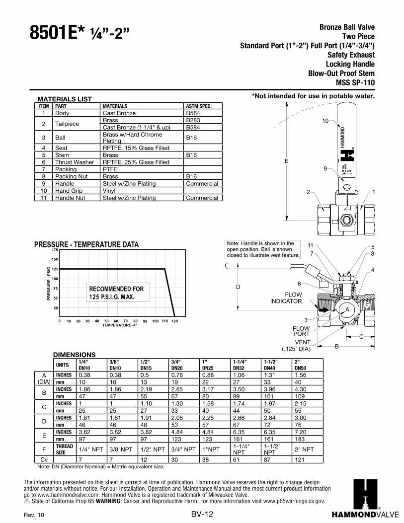
Note: Handle is shown in theopen position. Ball is shownclosed to illustrate vent feature.
D
4
57 8
11
A
FLOWPORTVENT
(.125” DIA)
3
6
FLOWINDICATOR
B
C
C
M
Y
CM
MY
CY
CMY
K
BA100ELD_REV10.PDF 1 8/6/14 2:09 PM
PRESSURE - TEMPERATURE DATA
0 10TEMPERATURE -F
ER
USSERP
-GISP
25
30 40
50
50 60
75
70 80
100
150
125
90
175
20 100 110 120
RECOMMENDED FORXAM.G.I.S.P .521
C
M
Y
CM
MY
CY
CMY
K
DIMENSIONSUNITS
1/4”DN10
3/8”DN10
1/2”DN15
3/4”DN20
1”DN25
1-1/4”DN32
1-1/2”DN40
2”DN50
A (DIA)
INCHES 0.38 0.38 0.5 0.76 0.88 1.06 1.31 1.56mm 10 10 13 19 22 27 33 40
BINCHES 1.86 1.86 2.19 2.65 3.17 3.50 3.96 4.30mm 47 47 55 67 80 89 101 109
CINCHES 1 1 1.10 1.30 1.58 1.74 1.97 2.15mm 25 25 27 33 40 44 50 55
DINCHES 1.81 1.81 1.91 2.08 2.25 2.66 2.84 3.00mm 46 46 48 53 57 67 72 76
EINCHES 3.82 3.82 3.82 4.84 4.84 6.35 6.35 7.20mm 97 97 97 123 123 161 161 183
F THREADSIZE 1/4" NPT 3/8"NPT 1/2" NPT 3/4" NPT 1"NPT 1-1/4"
NPT1-1/2" NPT 2" NPT
Cv 7 7 12 30 38 61 87 121Note: DN (Diameter Nominal) = Metric equivalent size.
MATERIALS LISTITEM PART MATERIALS ASTM SPEC.
1 Body Cast Bronze B584
2 TailpieceBrass B283Cast Bronze (1 1/4" & up) B584
3 Ball Brass w/Hard Chrome Plating B16
4 Seat RPTFE, 15% Glass Filled5 Stem Brass B166 Thrust Washer RPTFE, 25% Glass Filled7 Packing PTFE8 Packing Nut Brass B169 Handle Steel w/Zinc Plating Commercial10 Hand Grip Vinyl11 Handle Nut Steel w/Zinc Plating Commercial
*Not intended for use in potable water.
Bronze Ball ValveTwo Piece
Standard Port (1”-2”) Full Port (1/4”-3/4”)Safety ExhaustLocking Handle
Blow-Out Proof StemMSS SP-110
8501E* ¼”-2”
The information presented on this sheet is correct at time of publication. Hammond Valve reserves the right to change design and/or materials without notice. For our Installation, Operation and Maintenance Manual and the most current product information go to www.hammondvalve.com. Hammond Valve is a registered trademark of Milwaukee Valve.
State of California Prop 65 WARNING: Cancer and Reproductive Harm. For more information visit www.p65warnings.ca.gov.
BV-13Rev. 9
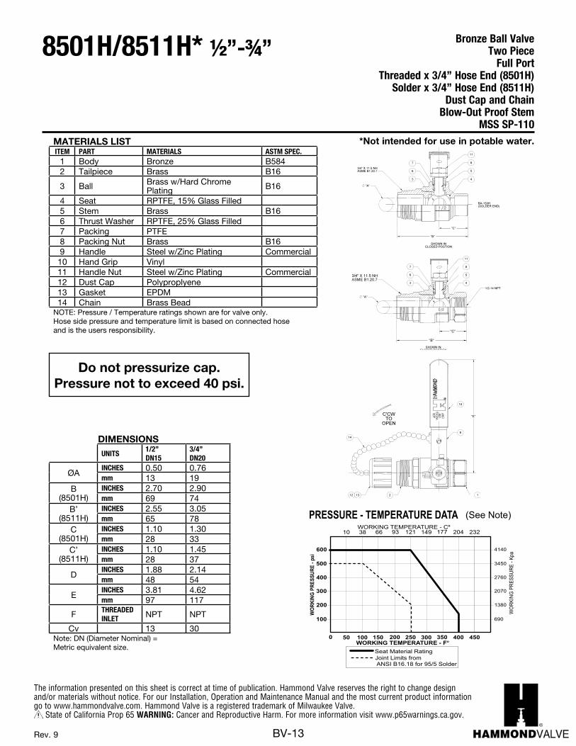
MATERIALS LISTITEM PART MATERIALS ASTM SPEC.
1 Body Bronze B5842 Tailpiece Brass B16
3 Ball Brass w/Hard Chrome Plating B16
4 Seat RPTFE, 15% Glass Filled5 Stem Brass B166 Thrust Washer RPTFE, 25% Glass Filled7 Packing PTFE8 Packing Nut Brass B169 Handle Steel w/Zinc Plating Commercial10 Hand Grip Vinyl11 Handle Nut Steel w/Zinc Plating Commercial12 Dust Cap Polyproplyene13 Gasket EPDM14 Chain Brass Bead
NOTE: Pressure / Temperature ratings shown are for valve only. Hose side pressure and temperature limit is based on connected hose and is the users responsibility.
DIMENSIONSUNITS
1/2”DN15
3/4”DN20
ØAINCHES 0.50 0.76mm 13 19
B (8501H)
INCHES 2.70 2.90mm 69 74
B’(8511H)
INCHES 2.55 3.05mm 65 78
C(8501H)
INCHES 1.10 1.30mm 28 33
C’(8511H)
INCHES 1.10 1.45mm 28 37
DINCHES 1.88 2.14mm 48 54
EINCHES 3.81 4.62mm 97 117
F THREADEDINLET NPT NPT
Cv 13 30Note: DN (Diameter Nominal) = Metric equivalent size.
Do not pressurize cap.Pressure not to exceed 40 psi.
690
1380
2070
2760
4140
3450
GNIKROW
ERUSSERP- p
is
WORKING TEMPERATURE - F
PRESSURE - TEMPERATURE DATA
100
200
300
400
600
500
0 50 150 200 250 300 350 400100
GNIKRO
WERUSSERP
-pKa
10WORKING TEMPERATURE - C
66 121 149 177 20438
Seat Material RatingJoint Limits fromANSI B16.18 for 95/5 Solder
93
450
232
(See Note)
BA100HA_REV10.PDF 10/9/2008 9:35:02 AM
BA100HA_REV10.PDF 1 3/4/14 9:22 AM
*Not intended for use in potable water.
Bronze Ball ValveTwo Piece Full Port
Threaded x 3/4” Hose End (8501H)Solder x 3/4” Hose End (8511H)
Dust Cap and ChainBlow-Out Proof Stem
MSS SP-110
8501H/8511H* ½”-¾”

The information presented on this sheet is correct at time of publication. Hammond Valve reserves the right to change design and/or materials without notice. For our Installation, Operation and Maintenance Manual and the most current product information go to www.hammondvalve.com. Hammond Valve is a registered trademark of Milwaukee Valve.
State of California Prop 65 WARNING: Cancer and Reproductive Harm. For more information visit www.p65warnings.ca.gov.
BV-14Rev. 4
B
Press End Adapter (4151 Series)
15
Do not pressurize cap.Pressure not to exceed 40 psi.
MATERIAL LISTITEM PART MATERIAL ASTM SPEC
1 Body Bronze B5842 Tailpiece Brass B16
3 BallBrass w/Hard Chrome Plating
B16
316 Stainless Steel (1) A2764 Seat RPTFE, 15% Glass Filled
5 StemBrass B16316 Stainless Steel (1) A276
6 Thrust Washer RPTFE, 25% Glass Filled7 Packing PTFE8 Packing Nut Brass B169 Handle Steel w/Zinc Plating Commercial10 Hand Grip Vinyl11 Handle Nut Steel w/Zinc Plating Commercial12 Dust Cap Polyproplyene13 Gasket EPDM14 Chain Brass Bead
15 Press Adapters Brass Fitting w/EPDM O-Ring B283
+NON-SHOCK(1) Ball & Stem are stainless steel for 8503H P1
DIMENSIONS
UNITS1/2” 3/4”
DN15 DN20
A INCHESmm
0.50 13
.7619
B INCHESmm
2.7069
2.9074
STDINSERTION
DEPTH
INCHESmm
.8722
.9825
C INCHESmm
1.1028
1.3033
D INCHESmm
1.8848
2.1454
E INCHESmm
3.8197
4.62117
F THREAD INLET NPT NPT
Cv 13 30
Note: DN (Diameter Nominal) = Metric equivalent size.
*Not intended for use in potable water.
Bronze Ball ValveTwo Piece Full Port
200 psig @ 250°F†Press x Hose End
Dust Cap and ChainBlow-Out Proof Stem
Conforms to MSS SP-110
8501H/8503H P1 ½”-¾”
The information presented on this sheet is correct at time of publication. Hammond Valve reserves the right to change design and/or materials without notice. For our Installation, Operation and Maintenance Manual and the most current product information go to www.hammondvalve.com. Hammond Valve is a registered trademark of Milwaukee Valve.
State of California Prop 65 WARNING: Cancer and Reproductive Harm. For more information visit www.p65warnings.ca.gov.
BV-15Rev. 10
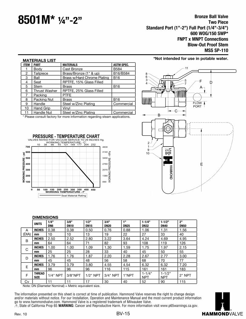
MATERIALS LISTITEM PART MATERIALS ASTM SPEC.
1 Body Cast Bronze B5842 Tailpiece Brass/Bronze (1" & up) B16/B5843 Ball Brass w/Hard Chrome Plating B164 Seat RPTFE, 15% Glass Filled5 Stem Brass B166 Thrust Washer RPTFE, 25% Glass Filled7 Packing PTFE8 Packing Nut Brass B169 Handle Steel w/Zinc Plating Commercial10 Hand Grip Vinyl11 Handle Nut Steel w/Zinc Plating Commercial
* Please consult factory for more information regarding steam applications.
DIMENSIONS
UNITS1/4”DN6
3/8”DN10
1/2”DN15
3/4”DN20
1”DN25
1-1/4”DN32
1-1/2”DN40
2”DN50
A (DIA)
INCHES 0.38 0.38 0.50 0.76 0.88 1.06 1.31 1.56mm 10 10 13 19 22 27 33 40
BINCHES 2.50 2.52 2.80 3.22 3.64 4.24 4.69 4.95mm 64 64 71 82 93 108 119 126
CINCHES 1.00 1.00 1.09 1.30 1.59 1.75 1.97 2.15mm 25 25 28 33 40 45 50 55
DINCHES 1.76 1.76 1.87 2.20 2.28 2.67 2.77 3.00mm 45 45 48 56 58 68 70 77
EINCHES 3.79 3.79 3.80 4.55 4.54 6.32 6.32 7.20mm 96 96 96 116 115 161 161 183
F THREADSIZE 1/4" NPT 3/8"NPT 1/2" NPT 3/4" NPT 1"NPT 1-1/4"
NPT1-1/2" NPT 2" NPT
Cv 11 11 17 30 40 52 90 115Note: DN (Diameter Nominal) = Metric equivalent size.
690
1380
2070
2760
4140
3450
4830
GNIKROW
ERUSSERP- p
is
WORKING TEMPERATURE - F
PRESSURE - TEMPERATURE CHART
100
200
300
400
600
500
700
0 50 150 200 250 300 350 400 450100
GNIKRO
WERUSSERP
-aPK
10WORKING TEMPERATURE - C
66 121 149 177 20438
Seat Material Rating
93
VALVES RATED FOR VACUUM SERVICE TO 29 INCHES Hg.
232
FLOWPORT
B
AD
C
E
12
34
5 F6
7
8
910
11
O P E N600W
OG
150S
WP
MILW
AU
KE
EVA
LVE
CO
MPA
NY,IN
CR
*Not intended for use in potable water.
Bronze Ball ValveTwo Piece
Standard Port (1”-2”) Full Port (1/4”-3/4”)600 WOG/150 SWP*
FNPT x MNPT ConnectionsBlow-Out Proof Stem
MSS SP-110
8501M* ¼”-2”
The information presented on this sheet is correct at time of publication. Hammond Valve reserves the right to change design and/or materials without notice. For our Installation, Operation and Maintenance Manual and the most current product information go to www.hammondvalve.com. Hammond Valve is a registered trademark of Milwaukee Valve.
State of California Prop 65 WARNING: Cancer and Reproductive Harm. For more information visit www.p65warnings.ca.gov.
BV-16
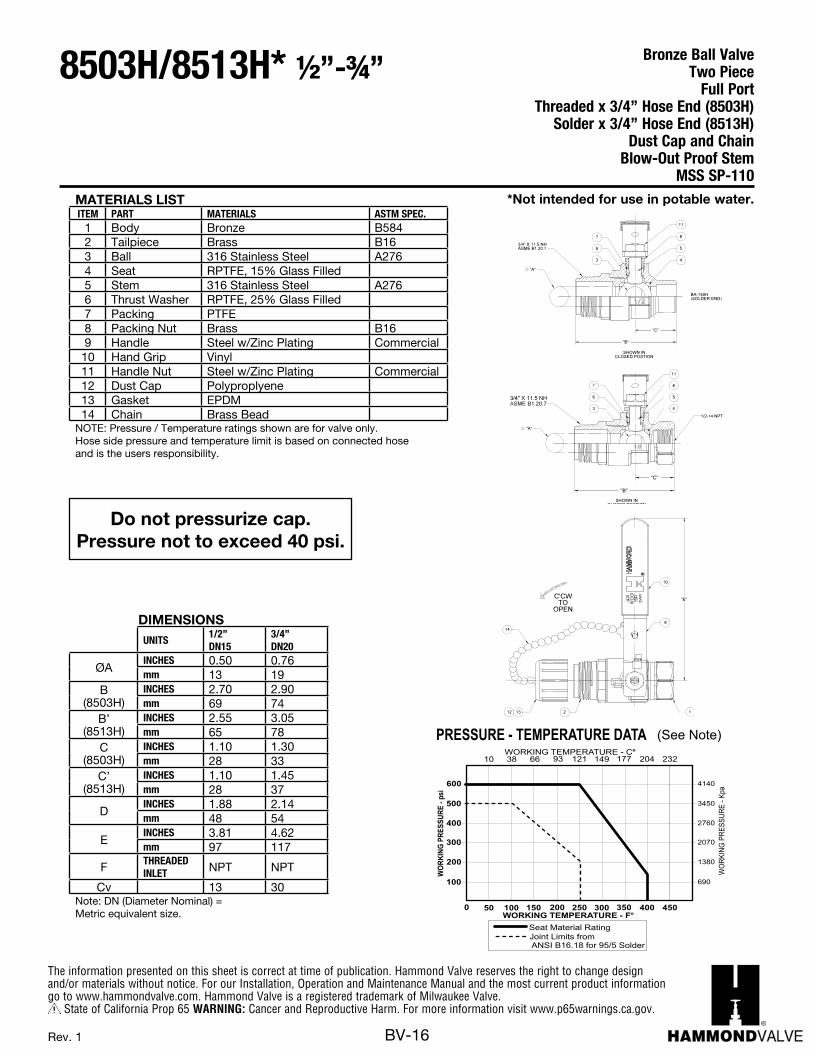
MATERIALS LISTITEM PART MATERIALS ASTM SPEC.
1 Body Bronze B5842 Tailpiece Brass B163 Ball 316 Stainless Steel A2764 Seat RPTFE, 15% Glass Filled5 Stem 316 Stainless Steel A2766 Thrust Washer RPTFE, 25% Glass Filled7 Packing PTFE8 Packing Nut Brass B169 Handle Steel w/Zinc Plating Commercial10 Hand Grip Vinyl11 Handle Nut Steel w/Zinc Plating Commercial12 Dust Cap Polyproplyene13 Gasket EPDM14 Chain Brass Bead
NOTE: Pressure / Temperature ratings shown are for valve only. Hose side pressure and temperature limit is based on connected hose and is the users responsibility.
DIMENSIONSUNITS
1/2”DN15
3/4”DN20
ØAINCHES 0.50 0.76mm 13 19
B (8503H)
INCHES 2.70 2.90mm 69 74
B’(8513H)
INCHES 2.55 3.05mm 65 78
C(8503H)
INCHES 1.10 1.30mm 28 33
C’(8513H)
INCHES 1.10 1.45mm 28 37
DINCHES 1.88 2.14mm 48 54
EINCHES 3.81 4.62mm 97 117
F THREADEDINLET NPT NPT
Cv 13 30Note: DN (Diameter Nominal) = Metric equivalent size.
Do not pressurize cap.Pressure not to exceed 40 psi.
690
1380
2070
2760
4140
3450
GNIKROW
ERUSSERP- p
is
WORKING TEMPERATURE - F
PRESSURE - TEMPERATURE DATA
100
200
300
400
600
500
0 50 150 200 250 300 350 400100
GNIKRO
WERUSSERP
-pKa
10WORKING TEMPERATURE - C
66 121 149 177 20438
Seat Material RatingJoint Limits fromANSI B16.18 for 95/5 Solder
93
450
232
(See Note)
BA100HA_REV10.PDF 10/9/2008 9:35:02 AM
BA100HA_REV10.PDF 1 3/4/14 9:22 AM
Bronze Ball ValveTwo Piece Full Port
Threaded x 3/4” Hose End (8503H)Solder x 3/4” Hose End (8513H)
Dust Cap and ChainBlow-Out Proof Stem
MSS SP-110
8503H/8513H* ½”-¾”
*Not intended for use in potable water.
Rev. 1
The information presented on this sheet is correct at time of publication. Hammond Valve reserves the right to change design and/or materials without notice. For our Installation, Operation and Maintenance Manual and the most current product information go to www.hammondvalve.com. Hammond Valve is a registered trademark of Milwaukee Valve.
State of California Prop 65 WARNING: Cancer and Reproductive Harm. For more information visit www.p65warnings.ca.gov.
BV-17Rev. 10
DIMENSIONS
UNITS3/8”DN10
1/2”DN15
3/4”DN20
1”DN25
1-1/4”DN32
1-1/2”DN40
2”DN50
2-1/2”DN65
3”DN80
A (DIA)
INCHES 0.38 0.50 0.76 0.88 1.06 1.31 1.56 2.00 2.31mm 10 13 19 22 27 33 40 51 59
BINCHES 2.10 2.39 3.05 3.71 4.54 5.00 6.25 7.34 8.16mm 52 59 75 91 111 123 153 180 200
CINCHES 0.90 1.07 1.56 1.76 2.27 2.50 3.13 3.67 4.07mm 22 26 38 43 56 61 77 90 100
DINCHES 1.80 1.89 2.13 2.29 2.67 2.85 3.02 3.47 3.88mm 44 46 52 56 65 70 74 85 95
EINCHES 3.81 3.81 4.56 4.56 6.31 6.31 7.19 7.19 7.19mm 93 93 112 112 155 155 176 176 176
F TUBESIZE 0.51 0.63 0.88 1.13 1.38 1.63 2.13 2.63 3.13
Cv 7 13 35 38 61 87 121 228 305Note: DN (Diameter Nominal) = Metric equivalent size.
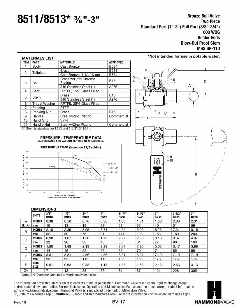
MATERIALS LISTITEM PART MATERIALS ASTM SPEC.
1 Body Cast Bronze B584
2 TailpieceBrass B283Cast Bronze (1 1/4" & up) B584
3 BallBrass w/Hard Chrome Plating B16
316 Stainless Steel (1) A2764 Seat RPTFE, 15% Glass Filled
5 StemBrass B16316 Stainless Steel (1) A276
6 Thrust Washer RPTFE, 25% Glass Filled7 Packing PTFE8 Packing Nut Brass B169 Handle Steel w/Zinc Plating Commercial10 Hand Grip Vinyl11 Handle Nut Steel w/Zinc Plating Commercial
(1) Stem is stainless for 8513 and 2-1/2”–3” 8511.
505
270
485
395
210
325
175
0
100
200
300
400
500
600
700
0 50 100 150 200 250
PRESSURE
psig
TEMPERATURE, Degrees FSolder Joint And Service As Per ANSI B16.18
PRESSURE VS TEMP. (based on 95/5 solder)
3/8 thru 1"
1 1/4 thru 2"
2 1/2 thru 4"
600
4” Only
B
A
F
D
C
E
2
910
11
1
57
34
6
8
O P E N600W
OG
150S
WP
MILW
AU
KE
EVA
LVE
CO
MPA
NY,IN
CR
VALVES RATED FOR VACUUM SERVICE TO 29 INCHES Hg.PRESSURE - TEMPERATURE DATA
B
A
F
D
C
E
2
910
11
1
57
34
6
8
O P E N600W
OG
150S
WP
MILW
AU
KE
EVA
LVE
CO
MPA
NY,IN
CR
VALVES RATED FOR VACUUM SERVICE TO 29 INCHES Hg.PRESSURE - TEMPERATURE DATA
*Not intended for use in potable water.
Bronze Ball ValveTwo Piece
Standard Port (1”-3”) Full Port (3/8”-3/4”)600 WOG
Solder EndsBlow-Out Proof Stem
MSS SP-110
8511/8513* ⅜”-3”

The information presented on this sheet is correct at time of publication. Hammond Valve reserves the right to change design and/or materials without notice. For our Installation, Operation and Maintenance Manual and the most current product information go to www.hammondvalve.com. Hammond Valve is a registered trademark of Milwaukee Valve.
State of California Prop 65 WARNING: Cancer and Reproductive Harm. For more information visit www.p65warnings.ca.gov.
BV-18Rev. 11
PRESSURE and TEMPERATURE CHART
690
1380
2070
2760
4140
3450
4830
GNIKROW
ERUSSERP- p
is
WORKING TEMPERATURE - F
100
200
300
400
600
500
700
0 50 150 200 250 300 350 400 450100
GNIKRO
WERUSSERP
-aPK
10WORKING TEMPERATURE - C
66 121 149 177 20438 93 232
VALVES RATED FOR VACUUM SERVICE TO 29 INCHES Hg.
Saturated Steam Limit
(1) Milwaukee Valve Company recommends the use
(2) Ball and stem are stainless for 300S.
of Stainless Steel ball and stem for steamapplications. Please consult factory for moreinformation.
11
12
1413
L
1 2
3
B
10
H7
8
5
4
69
W
A*
W
A
MATERIALS LISTITEM PART MATERIALS ASTM SPEC.
1 Body Cast Bronze B5842 End Cap Bronze B584
3 StemBrass B16316 Stainless Steel (2) A276
4 Packing Nut Brass B165 Packing PTFE6 Thrust Washer RPTFE, 25% Glass Filled
7 BallCP Brass B16316 Stainless Steel (2) A276
8 Seat RPTFE, 15% Glass Filled9 O-Ring Viton Commercial
10 Handle Steel w/Zinc Plating Commercial11 Handle Grip Vinyl Commercial12 Handle Nut Steel w/Zinc Plating Commercial13 Bolt Steel w/Zinc Plating Commercial14 Nut Steel w/Zinc Plating Commercial
(1) Hammond Valve recommends the use of Stainless Steel ball and stem for steam applications. Please consult factory for more information. (2) Ball and stem are stainless for 8603
DIMENSIONS
UNITS1/4”DN6
3/8”DN10
1/2”DN15
3/4”DN20
1”D25
1-1/4”D32
1-1/2”D40
2”D50
2-1/2”DN 65
3” *DN 80
AINCHES 0.50 0.50 0.50 0.75 1 1.25 1.50 2.00 2.50 2.50mm 13 13 13 19 25 32 38 51 64 64
BINCHES 3.03 3.03 3.03 3.65 3.82 4.86 5.06 6.00 7.00 7.00mm 77 77 77 90 97 123 129 152 178 178
HINCHES 1.65 1.65 1.65 2.24 2.65 2.86 3.03 3.26 4.09 4.09mm 42 42 42 57 67 73 77 83 104 104
LINCHES 4.03 4.03 4.06 4.58 6.30 6.32 7.20 7.20 8.00 8.00mm 102 102 103 116 160 161 183 183 203 203
WINCHES 1.95 1.95 1.95 2.19 2.48 3.00 3.13 3.78 6.25 6.25mm 50 50 50 56 63 76 80 96 159 159
F THREADSIZE
1/4” NPT
3/8”NPT
1/2”NPT
3/4”NPT 1” NPT 1-1/4”
NPT1-1/2”NPT 2” NPT 2-1/2”
NPT 3” NPT
Cv 7 7 17 31 60 110 185 360 390 390Note: DN (Diameter Nominal) = Metric equivalent size.* 3” is Standard Port.
*Not intended for use in potable water.
Bronze Ball ValveThree Piece
Full Port600 WOG/150 SWP (1)
Threaded EndsBlow-Out Proof Stem
MSS SP-110
8604/8603* ¼”-3”
1/4”-2” Sizes 2-1/2”-3” Sizes
The information presented on this sheet is correct at time of publication. Hammond Valve reserves the right to change design and/or materials without notice. For our Installation, Operation and Maintenance Manual and the most current product information go to www.hammondvalve.com. Hammond Valve is a registered trademark of Milwaukee Valve.
State of California Prop 65 WARNING: Cancer and Reproductive Harm. For more information visit www.p65warnings.ca.gov.
BV-19Rev. 4
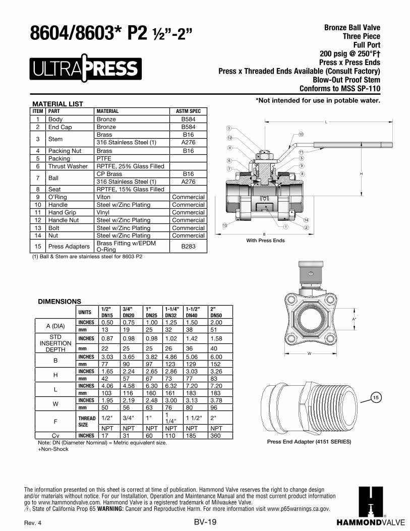
W
A*
11
12
1413
L
1 2
3
B
10
H7
8
5
4
69
With Press Ends
MATERIAL LISTITEM PART MATERIAL ASTM SPEC
1 Body Bronze B5842 End Cap Bronze B584
3 StemBrass B16316 Stainless Steel (1) A276
4 Packing Nut Brass B165 Packing PTFE6 Thrust Washer RPTFE, 25% Glass Filled
7 BallCP Brass B16316 Stainless Steel (1) A276
8 Seat RPTFE, 15% Glass Filled9 O’Ring Viton Commercial
10 Handle Steel w/Zinc Plating Commercial11 Hand Grip Vinyl Commercial12 Handle Nut Steel w/Zinc Plating Commercial13 Bolt Steel w/Zinc Plating Commercial14 Nut Steel w/Zinc Plating Commercial
15 Press Adapters Brass Fitting w/EPDM O-Ring B283
(1) Ball & Stem are stainless steel for 8603 P2
Press End Adapter (4151 SERIES)
15
DIMENSIONS
UNITS1/2”DN15
3/4”DN20
1”DN25
1-1/4”DN32
1-1/2”DN40
2”DN50
A (DIA)INCHES 0.50 0.75 1.00 1.25 1.50 2.00mm 13 19 25 32 38 51
STD INSERTION
DEPTH
INCHES 0.87 0.98 0.98 1.02 1.42 1.58
mm 22 25 25 26 36 40
BINCHES 3.03 3.65 3.82 4.86 5.06 6.00mm 77 90 97 123 129 152
HINCHES 1.65 2.24 2.65 2.86 3.03 3.26mm 42 57 67 73 77 83
LINCHES 4.06 4.58 6.30 6.32 7.20 7.20mm 103 116 160 161 183 183
WINCHES 1.95 2.19 2.48 3.00 3.13 3.78mm 50 56 63 76 80 96
F THREAD SIZE
1/2" 3/4" 1" 1 1/4" 1 1/2" 2"
NPT NPT NPT NPT NPT NPTCv INCHES 17 31 60 110 185 360
Note: DN (Diameter Nominal) = Metric equivalent size. +Non-Shock
*Not intended for use in potable water.
Bronze Ball ValveThree Piece
Full Port200 psig @ 250°F†Press x Press Ends
Press x Threaded Ends Available (Consult Factory)Blow-Out Proof Stem
Conforms to MSS SP-110
8604/8603* P2 ½”-2”
The information presented on this sheet is correct at time of publication. Hammond Valve reserves the right to change design and/or materials without notice. For our Installation, Operation and Maintenance Manual and the most current product information go to www.hammondvalve.com. Hammond Valve is a registered trademark of Milwaukee Valve.
State of California Prop 65 WARNING: Cancer and Reproductive Harm. For more information visit www.p65warnings.ca.gov.
BV-20Rev. 10
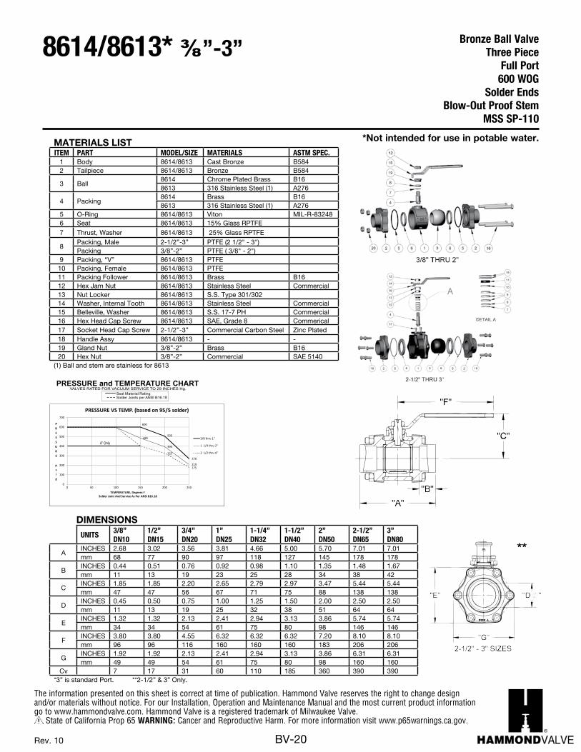
MATERIALS LISTITEM PART MODEL/SIZE MATERIALS ASTM SPEC.
1 Body 8614/8613 Cast Bronze B5842 Tailpiece 8614/8613 Bronze B584
3 Ball8614 Chrome Plated Brass B168613 316 Stainless Steel (1) A276
4 Packing8614 Brass B168613 316 Stainless Steel (1) A276
5 O-Ring 8614/8613 Viton MIL-R-832486 Seat 8614/8613 15% Glass RPTFE7 Thrust, Washer 8614/8613 25% Glass RPTFE
8Packing, Male 2-1/2”-3” PTFE (2 1/2" - 3")Packing 3/8”-2” PTFE ( 3/8" - 2")
9 Packing, “V” 8614/8613 PTFE 10 Packing, Female 8614/8613 PTFE11 Packing Follower 8614/8613 Brass B1612 Hex Jam Nut 8614/8613 Stainless Steel Commercial13 Nut Locker 8614/8613 S.S. Type 301/30214 Washer, Internal Tooth 8614/8613 Stainless Steel Commercial15 Belleville, Washer 8614/8613 S.S. 17-7 PH Commercial16 Hex Head Cap Screw 8614/8613 SAE, Grade 8 Commerical17 Socket Head Cap Screw 2-1/2”-3” Commercial Carbon Steel Zinc Plated18 Handle Assy 8614/8613 - -19 Gland Nut 3/8”-2” Brass B1620 Hex Nut 3/8”-2” Commercial SAE 5140
(1) Ball and stem are stainless for 8613
**
505
270
485
395
210
325
175
0
100
200
300
400
500
600
700
0 50 100 150 200 250
PRESSURE
psig
TEMPERATURE, Degrees FSolder Joint And Service As Per ANSI B16.18
PRESSURE VS TEMP. (based on 95/5 solder)
3/8 thru 1"
1 1/4 thru 2"
2 1/2 thru 4"
600
4” Only
BA-350/350S 12"/ - "
BRONZE-PIECE, FULL-PORT
600 WOGSOLDERED ENDSBLOW-OUT PROOF STEM
BALL VALVETHREE
MSS SP-110
(1) Ball and stem are stainless for 350S
PRESSURE and TEMPERATURE CHARTSeat Material RatingSolder Joints per ANSI B16.18
VALVES RATED FOR VACUUM SERVICE TO 29 INCHES Hg.
3
DIMENSIONS
UNITS3/8”DN10
1/2”DN15
3/4”DN20
1”DN25
1-1/4”DN32
1-1/2”DN40
2”DN50
2-1/2”DN65
3”DN80
AINCHES 2.68 3.02 3.56 3.81 4.66 5.00 5.70 7.01 7.01mm 68 77 90 97 118 127 145 178 178
BINCHES 0.44 0.51 0.76 0.92 0.98 1.10 1.35 1.48 1.67mm 11 13 19 23 25 28 34 38 42
CINCHES 1.85 1.85 2.20 2.65 2.79 2.97 3.47 5.44 5.44mm 47 47 56 67 71 75 88 138 138
DINCHES 0.45 0.50 0.75 1.00 1.25 1.50 2.00 2.50 2.50mm 11 13 19 25 32 38 51 64 64
EINCHES 1.32 1.32 2.13 2.41 2.94 3.13 3.86 5.74 5.74mm 34 34 54 61 75 80 98 146 146
FINCHES 3.80 3.80 4.55 6.32 6.32 6.32 7.20 8.10 8.10mm 96 96 116 160 160 160 183 206 206
GINCHES 1.92 1.92 2.13 2.41 2.94 3.13 3.86 6.31 6.31mm 49 49 54 61 75 80 98 160 160
Cv 7 17 31 60 110 185 360 390 390*3” is standard Port. **2-1/2” & 3” Only.
*Not intended for use in potable water.
Bronze Ball ValveThree Piece
Full Port600 WOG
Solder EndsBlow-Out Proof Stem
MSS SP-110
8614/8613* ⅜”-3”
The information presented on this sheet is correct at time of publication. Hammond Valve reserves the right to change design and/or materials without notice. For our Installation, Operation and Maintenance Manual and the most current product information go to www.hammondvalve.com. Hammond Valve is a registered trademark of Milwaukee Valve.
State of California Prop 65 WARNING: Cancer and Reproductive Harm. For more information visit www.p65warnings.ca.gov.
BV-21Rev. 6
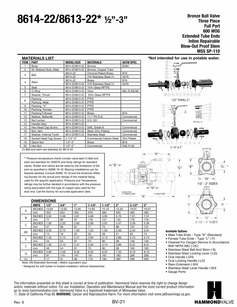
MATERIALS LISTITEM PART MODEL/SIZE MATERIALS ASTM SPEC.
1 Body 8614-22/8613-22 Bronze B5842 Sil. Braised Stub, Male 8614-22/8613-22 Bronze, Copper Tube
3 Ball8614-22 Chrome Plated Brass B168613-22 316 Stainless Steel (1) A276
4 Stem8614-22 Brass B168614-22/8613-22 316 Stainless Steel (1) A276
5 Seat 8614-22/8613-22 15% Glass RPTFE6 O-Ring 8614-22/8613-22 Viton MIL-R-832487 Washer, Thrust 8614-22/8613-22 25% Glass RPTFE
8Packing 8614-22/8613-22 PTFE Packing, Male 8614-22/8613-22 PTFE
9 Packing, “V” 8614-22/8613-22 PTFE 10 Packing, Female 8614-22/8613-22 PTFE11 Packing Follower 8614-22/8613-22 Brass B1612 Washer, Belleville 8614-22/8613-22 17-7 PH S.S. Commercial13 Nut Locker 8614-22/8613-22 S.S. 301 Commercial14 Handle Assy 8614-22/8613-22 -15 Hex Head Cap Screw 8614-22/8613-22 SAE, Grade 8 Commerical16 Nut, Jam 8614-22/8613-22 Steel, Zinc Plating Commercial17 Washer, Internal Tooth 8614-22/8613-22 Stainless Steel Commercial18 Socket Head Cap Screw 2-1/2”-3” Commercial Carbon Steel Zinc Plated19 Gland Nut 1/2”-2” Brass B1620 Hex Nut 1/2”-2” Commercial SAE 5140
(1) Ball and stem are stainless for 8613-22
DIMENSIONSUNITS 1/2” 3/4” 1” 1-1/4” 1-1/2” 2” 2-1/2” 3”
AINCHES 13.84 13.92 13.95 14.82 15.10 15.50 19.01 19.01mm 352 354 354 376 384 394 483 483
BINCHES 3.02 3.56 3.81 4.66 5.00 5.70 7.01 7.01mm 77 90 97 118 127 145 178 178
CINCHES 1.85 2.20 2.65 2.80 2.97 3.47 5.39 5.39mm 47 56 67 71 75 88 137 137
ØDINCHES 0.50 0.75 1.00 1.25 1.50 2.00 2.44 2.91mm 13 19 25 32 38 51 62 74
EINCHES 1.32 2.13 2.41 2.94 3.13 3.86 5.74 5.74mm 34 54 61 75 80 98 146 146
FINCHES 1.92 2.13 2.41 2.94 3.13 3.86 6.31 6.31mm 49 54 61 75 80 98 160 160
GINCHES 3.80 4.56 6.32 6.32 6.32 7.20 8.10 8.10mm 97 116 161 161 161 183 206 206
Cv 17 31 60 110 185 360 390 390Note: DN (Diameter Nominal) = Metric equivalent size. * Designed for soft solder or brazed installation without disassembly.
** Pressure temperature charts contain valve seat (1) Ball and stem are stainless for 350STE and body ratings for standard valves. Solder end valves are de-rated by the limitations of the joint as specified in ASME 16.18. Brazing installations can be likewise derated. Consult ASME 16.18 and the American Weld-ing Society for the actual joint ratings of the material being used for the specific application. Pressure and Temperature ratings may be further derated in accordance with the pressure rating associated with the type of copper tube used for the stub end. Call the factory for accurate application data.
Available Options• Male Tube Ends - Type “K” (Standard)• Female Tube Ends - Type “L” (-F)• Cleaned For Oxygen Service In Accordance
With NFPA 99C (-OC)• Stainless-Steel Ball And Stem (-S)• Stainless-Steel Locking Lever (-LD)• Oval Handle (-OH)• Oval Locking Handle (-LO)• Stem Extension (-XH)• Stainless-Steel Lever Handle (-SH)• Gauge Ports
*Not intended for use in potable water.
Bronze Ball ValveThree Piece
Full Port600 WOG
Extended Tube EndsInline Repairable
Blow-Out Proof StemMSS SP-110
8614-22/8613-22* ½”-3”
The information presented on this sheet is correct at time of publication. Hammond Valve reserves the right to change design and/or materials without notice. For our Installation, Operation and Maintenance Manual and the most current product information go to www.hammondvalve.com. Hammond Valve is a registered trademark of Milwaukee Valve.
State of California Prop 65 WARNING: Cancer and Reproductive Harm. For more information visit www.p65warnings.ca.gov.
BV-22Rev. 6
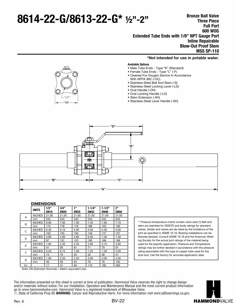
Available Options• Male Tube Ends - Type “K” (Standard)• Female Tube Ends - Type “L” (-F)• Cleaned For Oxygen Service In Accordance
With NFPA 99C (-OC)• Stainless-Steel Ball And Stem (-S)• Stainless-Steel Locking Lever (-LD)• Oval Handle (-OH)• Oval Locking Handle (-LO)• Stem Extension (-XH)• Stainless-Steel Lever Handle (-SH)
BA-350TE-G/350STE-GBRONZE
-PIECE, FULL-PORT600 WOG / 150 SWPEXTENDED TUBE ENDS WITH 1/8” NPT GAUGE PORTIN-LINE REPAIRABLEBLOW-OUT PROOF STEM
BALL VALVETHREE
BA350ste_rev2.CDR
MSS SP-110
* Designed for soft solder or brazed installationwithout disassembly.
Pressure temperature charts contain valve seatand body ratings for standard valves. Solderend valves are de-rated by the limitations of thejoint as specified in ASME 16.18. Brazinginstallations can be likewise derated. ConsultASME 16.18 and the American Welding Societyfor the actual joint ratings of the material beingused for the specific application.Pressure and Temperature ratings may befurther derated in accordance with the pressurerating associated with the type of copper tubeUsed for the stub end. Call the factory foraccurate application data.
1/2”-2”
Available Options.* Male Tube Ends-Type “K” (Standard)* Female Tube Ends-Type “L” (-F)* Cleaned For Oxygen Service
Accordance With NFPA 99 (-OC)* Stainless Steel Ball And Stem (-S)
* Oval Handle (-OH) * Oval Locking Handle (-LO)* Stem Extension (-XH)* Stainless Steel Lever Handle (-SH)
“W”
“ F”
MILWAUKEE VALVE
The information presented on this sheet is correct at the time of publication. Milwaukee Valve Company reserves the right to changedesign, and/or material specifications without notice. For the most current information access www.milwaukeevalve.com
“B”
“D”
“E”
“A”
“C”
1/2" 3/4" 1" 1-1/4" 1-1/2" 2"DN15 DN20 DN25 DN32 DN40 DN50
mm 533 533 533 533 533 533
mm 175 178 178 188 193 196C INCH 6.4 6.1 5.9 5.5 5.4 5
mm 163 155 150 140 137 127D INCH 3.8 4.8 4.8 6.5 7.4 7.4
mm 97 122 122 165 188 188E INCH 1.6 2.3 2.4 2.8 3.1 3.6
mm 41 58 61 71 79 91ØF INCH 0.5 0.75 1 1.25 1.5 2
mm 13 19 25 32 38 51
mm 48 56 64 76 76 102
Cv 17 31 60 110 185 360Note: DN (Diameter Nominal) = Metric equivalent size
NCH 6.9 7 7 7.4 7.6 7.7
A INCH 21 21 21 21 21 21
* S tainless S teel Locking Lever (-LD)
W INCH 1.9 2.2 2. 5 3 3 4
UNITS
DIMENSIONS
Rev. 3
** Pressure temperature charts contain valve seat (1) Ball and stem are stainless for 350STE and body ratings for standard valves. Solder end valves are de-rated by the limitations of the joint as specified in ASME 16.18. Brazing installations can be likewise derated. Consult ASME 16.18 and the American Weld-ing Society for the actual joint ratings of the material being used for the specific application. Pressure and Temperature ratings may be further derated in accordance with the pressure rating associated with the type of copper tube used for the stub end. Call the factory for accurate application data.
DIMENSIONS
UNITS1/2”DN15
3/4”DN20
1”DN25
1-1/4”DN32
1-1/2”DN40
2”DN50
AINCHES 21.00 21.00 21.00 21.00 21.00 21.00mm 533 533 533 533 533 533
BINCHES 6.90 7.00 7.00 7.40 7.60 7.70mm 175 178 178 188 193 196
CINCHES 6.40 6.10 5.90 5.50 5.40 5.00mm 163 155 150 140 137 127
DINCHES 3.80 4.80 4.80 6.50 7.40 7.40mm 97 122 122 165 188 188
EINCHES 1.60 2.30 2.40 2.80 3.10 3.60mm 41 58 61 71 79 91
FINCHES 0.50 0.75 1.00 1.25 1.50 2.00mm 13 19 25 32 38 51
GINCHES 1.90 2.20 2.50 3.00 3.00 4.00mm 48 56 64 76 76 102
Cv 17 31 60 110 185 360Note: DN (Diameter Nominal) = Metric equivalent size.
*Not intended for use in potable water.
Bronze Ball ValveThree Piece
Full Port600 WOG
Extended Tube Ends with 1/8” NPT Gauge PortInline Repairable
Blow-Out Proof StemMSS SP-110
8614-22-G/8613-22-G* ½”-2”
The information presented on this sheet is correct at time of publication. Hammond Valve reserves the right to change design and/or materials without notice. For our Installation, Operation and Maintenance Manual and the most current product information go to www.hammondvalve.com. Hammond Valve is a registered trademark of Milwaukee Valve.
State of California Prop 65 WARNING: Cancer and Reproductive Harm. For more information visit www.p65warnings.ca.gov.
BV-23Rev. 6
*Not intended for use in potable water.
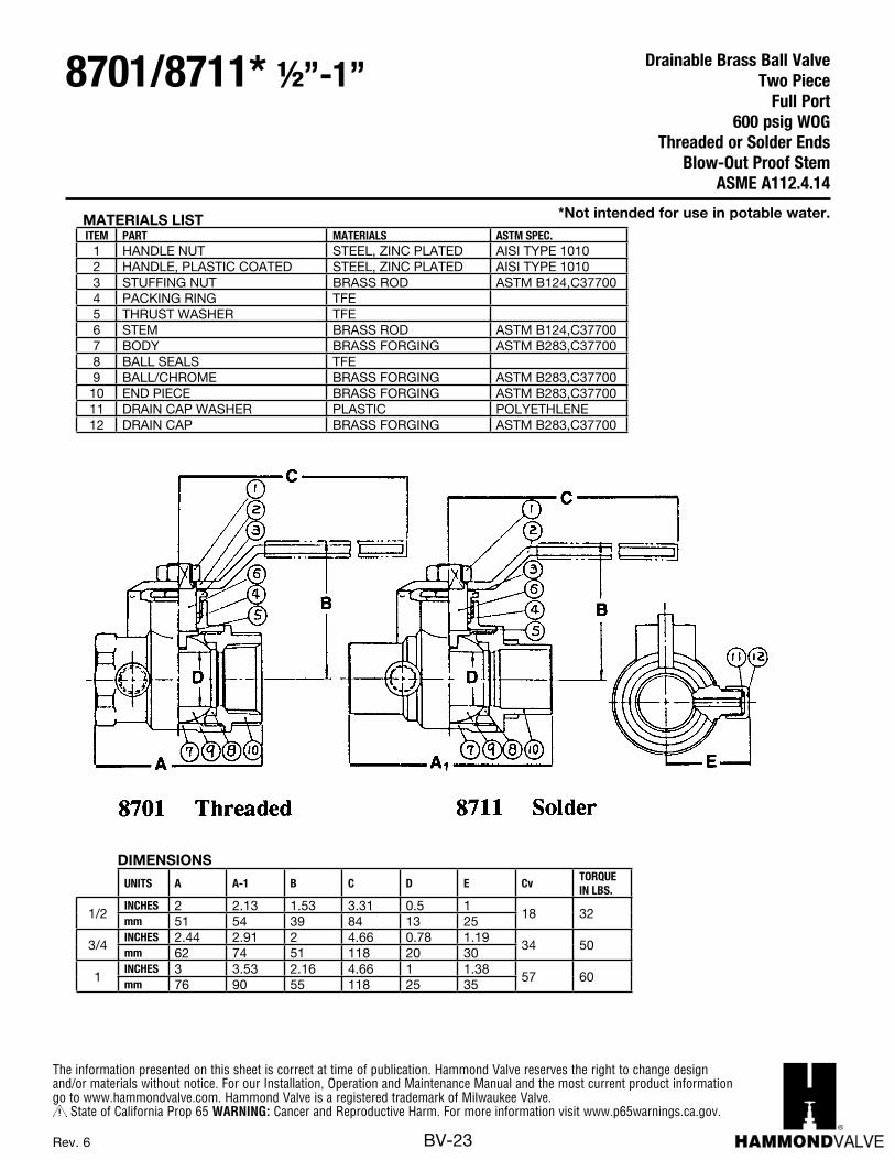
Drainable Brass Ball ValveTwo Piece
Full Port600 psig WOG
Threaded or Solder EndsBlow-Out Proof Stem
ASME A112.4.14
8701/8711* ½”-1”
DIMENSIONS
UNITS A A-1 B C D E CvTORQUEIN LBS.
1/2INCHES 2 2.13 1.53 3.31 0.5 1
18 32mm 51 54 39 84 13 25
3/4INCHES 2.44 2.91 2 4.66 0.78 1.19
34 50mm 62 74 51 118 20 30
1INCHES 3 3.53 2.16 4.66 1 1.38
57 60mm 76 90 55 118 25 35
MATERIALS LISTITEM PART MATERIALS ASTM SPEC.
1 HANDLE NUT STEEL, ZINC PLATED AISI TYPE 10102 HANDLE, PLASTIC COATED STEEL, ZINC PLATED AISI TYPE 10103 STUFFING NUT BRASS ROD ASTM B124,C377004 PACKING RING TFE5 THRUST WASHER TFE6 STEM BRASS ROD ASTM B124,C377007 BODY BRASS FORGING ASTM B283,C377008 BALL SEALS TFE9 BALL/CHROME BRASS FORGING ASTM B283,C37700
10 END PIECE BRASS FORGING ASTM B283,C3770011 DRAIN CAP WASHER PLASTIC POLYETHLENE12 DRAIN CAP BRASS FORGING ASTM B283,C37700
The information presented on this sheet is correct at time of publication. Hammond Valve reserves the right to change design and/or materials without notice. For our Installation, Operation and Maintenance Manual and the most current product information go to www.hammondvalve.com. Hammond Valve is a registered trademark of Milwaukee Valve.
State of California Prop 65 WARNING: Cancer and Reproductive Harm. For more information visit www.p65warnings.ca.gov.
BV-24Rev. 21
BRASS BALL VALVE***
967
4
10
3
5
2
1
8 11
D
E
A
F
"BA-475B" 14 -"/ 4 "
RC US
UL 842UL 125ANSI Z 21.15a CGA 9.1a
ASME B16.44
R
690
1380
2070
2760
4140
3450
4830
GNIKROW
ERUSSERPp-
si
WORKING TEMPERATURE - F
PRESSURE - TEMPERATURE CHART
100
200
300
400
600
500
700
0 50 150 200 250 300 350 400 450100
GNIKRO
WERUSSERP
-aPK
10WORKING TEMPERATURE - C
66 121 149 177 20438 93
CB
Seat Material Rating
MATERIALS LISTITEM PART MATERIALS ASTM SPEC.
1 Body Brass, Forged B2832 Tailpiece Brass, Forged B283
3 Ball CP Brass 3/8” - 1-1/4”CP Brass, Cast 1-1/2 - 4” B584
4 Ball Seal PTFE Commercial5 Stem Brass B1246 O-Ring Buna-N D20067 ThrustWasher PTFE Commercial8 Gland Nut Brass B169 Packing PTFE Commercial
10 Handle Zinc Plated Steel Commercial11 Handle Nut Zinc Plated Steel Commercial
DIMENSIONS
C US600 WOG (1/4”-3”) 400 WOG (4”)TWO-PIECE, FULL-PORT MSS-SP110
ASME A112.4.14
1/4” through 2” Only
Also Available BA-475B-LL (Locks Only In Closed Position)
THREADED ENDSBLOW-OUT PROOF STEM
*
*
B283
Not Suitable For Ammonia.Not intended for use in potable water.4” Valve Only
**
**
***
APPROVED1140
****12 Body Seal PTFE Commercial
****
4” Only
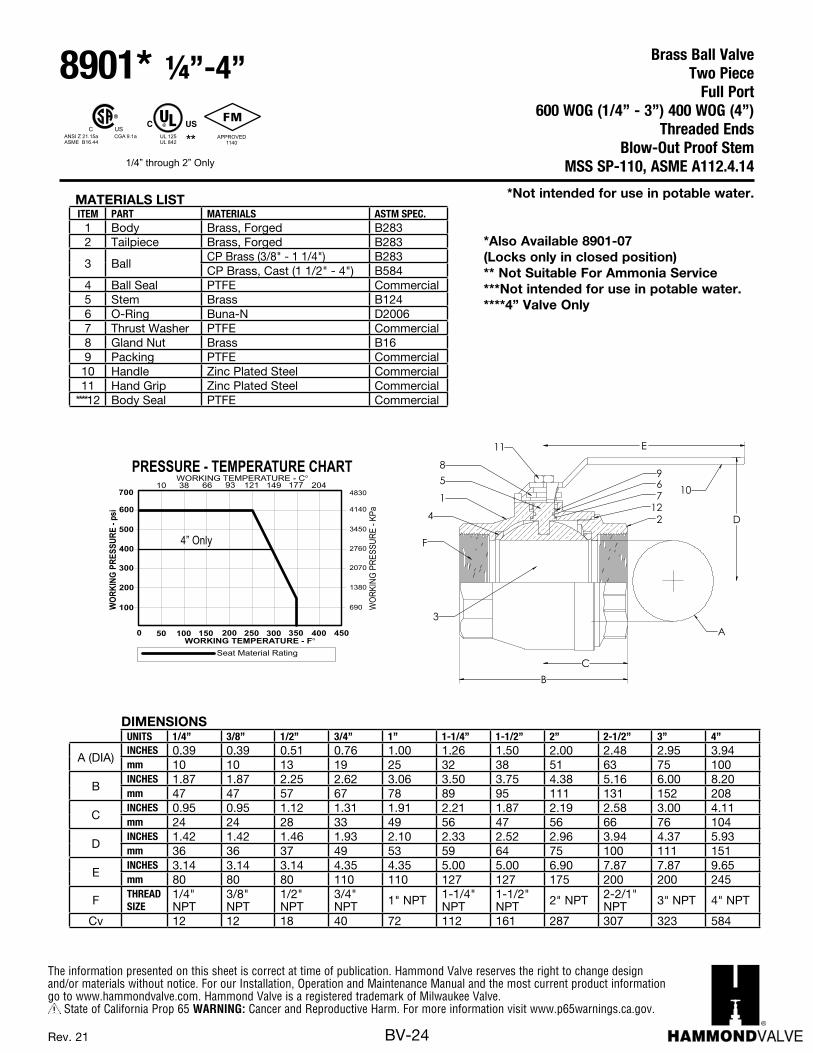
DIMENSIONSUNITS 1/4” 3/8” 1/2” 3/4” 1” 1-1/4” 1-1/2” 2” 2-1/2” 3” 4”
A (DIA)INCHES 0.39 0.39 0.51 0.76 1.00 1.26 1.50 2.00 2.48 2.95 3.94mm 10 10 13 19 25 32 38 51 63 75 100
BINCHES 1.87 1.87 2.25 2.62 3.06 3.50 3.75 4.38 5.16 6.00 8.20mm 47 47 57 67 78 89 95 111 131 152 208
CINCHES 0.95 0.95 1.12 1.31 1.91 2.21 1.87 2.19 2.58 3.00 4.11mm 24 24 28 33 49 56 47 56 66 76 104
DINCHES 1.42 1.42 1.46 1.93 2.10 2.33 2.52 2.96 3.94 4.37 5.93mm 36 36 37 49 53 59 64 75 100 111 151
EINCHES 3.14 3.14 3.14 4.35 4.35 5.00 5.00 6.90 7.87 7.87 9.65mm 80 80 80 110 110 127 127 175 200 200 245
F THREAD SIZE
1/4" NPT
3/8" NPT
1/2" NPT
3/4" NPT 1" NPT 1-1/4"
NPT1-1/2" NPT 2" NPT 2-2/1"
NPT 3" NPT 4" NPT
Cv 12 12 18 40 72 112 161 287 307 323 584
MATERIALS LISTITEM PART MATERIALS ASTM SPEC.
1 Body Brass, Forged B2832 Tailpiece Brass, Forged B283
3 BallCP Brass (3/8" - 1 1/4") B283CP Brass, Cast (1 1/2" - 4") B584
4 Ball Seal PTFE Commercial5 Stem Brass B1246 O-Ring Buna-N D20067 Thrust Washer PTFE Commercial8 Gland Nut Brass B169 Packing PTFE Commercial10 Handle Zinc Plated Steel Commercial11 Hand Grip Zinc Plated Steel Commercial
****12 Body Seal PTFE Commercial
*Not intended for use in potable water.
*Also Available 8901-07 (Locks only in closed position)** Not Suitable For Ammonia Service***Not intended for use in potable water.****4” Valve Only
Brass Ball ValveTwo Piece
Full Port600 WOG (1/4” - 3”) 400 WOG (4”)
Threaded EndsBlow-Out Proof Stem
MSS SP-110, ASME A112.4.14
8901* ¼”-4”
The information presented on this sheet is correct at time of publication. Hammond Valve reserves the right to change design and/or materials without notice. For our Installation, Operation and Maintenance Manual and the most current product information go to www.hammondvalve.com. Hammond Valve is a registered trademark of Milwaukee Valve.
State of California Prop 65 WARNING: Cancer and Reproductive Harm. For more information visit www.p65warnings.ca.gov.
BV-25Rev. 14
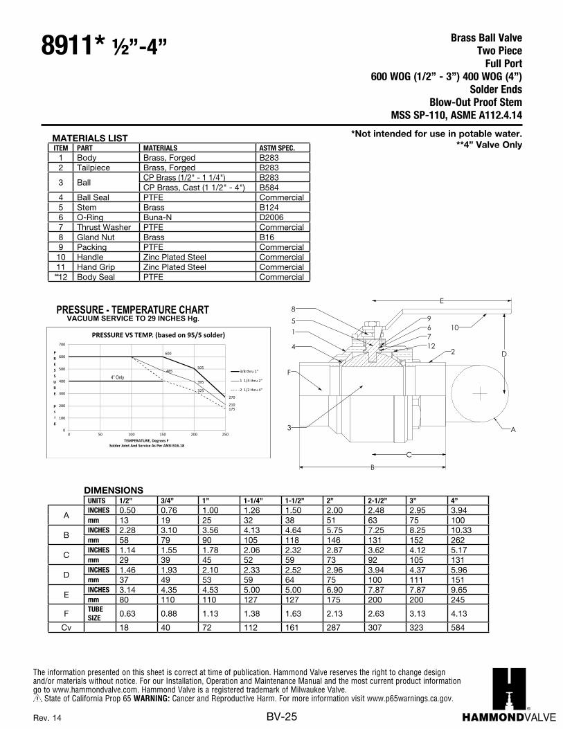
MATERIALS LISTITEM PART MATERIALS ASTM SPEC.
1 Body Brass, Forged B2832 Tailpiece Brass, Forged B283
3 BallCP Brass (1/2" - 1 1/4") B283CP Brass, Cast (1 1/2" - 4") B584
4 Ball Seal PTFE Commercial5 Stem Brass B1246 O-Ring Buna-N D20067 Thrust Washer PTFE Commercial8 Gland Nut Brass B169 Packing PTFE Commercial10 Handle Zinc Plated Steel Commercial11 Hand Grip Zinc Plated Steel Commercial**12 Body Seal PTFE Commercial
DIMENSIONSUNITS 1/2” 3/4” 1” 1-1/4” 1-1/2” 2” 2-1/2” 3” 4”
AINCHES 0.50 0.76 1.00 1.26 1.50 2.00 2.48 2.95 3.94mm 13 19 25 32 38 51 63 75 100
BINCHES 2.28 3.10 3.56 4.13 4.64 5.75 7.25 8.25 10.33mm 58 79 90 105 118 146 131 152 262
CINCHES 1.14 1.55 1.78 2.06 2.32 2.87 3.62 4.12 5.17mm 29 39 45 52 59 73 92 105 131
DINCHES 1.46 1.93 2.10 2.33 2.52 2.96 3.94 4.37 5.96mm 37 49 53 59 64 75 100 111 151
EINCHES 3.14 4.35 4.53 5.00 5.00 6.90 7.87 7.87 9.65mm 80 110 110 127 127 175 200 200 245
F TUBE SIZE 0.63 0.88 1.13 1.38 1.63 2.13 2.63 3.13 4.13
Cv 18 40 72 112 161 287 307 323 584
"BA-485B" 1/2" - 4"BRASS BALL VALVE MSS SP-110
ASME A112.4.14
SOLDERED ENDSBLOW-OUT PROOF STEM
600 PSIG WOG (1/2”-3”) 400 WOG (4”) TWO PIECE, FULL PORT
967
4
10
3
5
2
1
8 11
A
F
B
E
D
C
DIMENSIONS
PRESSURE - TEMPERATURE CHARTVACUUM SERVICE TO 29 INCHES Hg.
MATERIALS LISTITEM PART MATERIALS ASTM SPEC.
1 Body Brass, Forged B2832 Tailpiece Brass, Forged B283
3 Ball CP Brass 1/2” - 1-1/4”CP Brass, Cast 1-1/2 - 4” B584
4 Ball Seal PTFE Commercial5 Stem Brass B1246 O-Ring Buna-N D20067 ThrustWasher PTFE Commercial8 Gland Nut Brass B169 Packing PTFE Commercial
10 Handle Zinc Plated Steel Commercial11 Handle Nut Zinc Plated Steel Commercial
B283
**12 Body Seal PTFE Commercial
505
270
485
395
210
325
175
0
100
200
300
400
500
600
700
0 50 100 150 200 250
PRESSURE
psig
TEMPERATURE, Degrees FSolder Joint And Service As Per ANSI B16.18
PRESSURE VS TEMP. (based on 95/5 solder)
3/8 thru 1"
1 1/4 thru 2"
2 1/2 thru 4"
600
4” Only
Brass Ball ValveTwo Piece
Full Port600 WOG (1/2” - 3”) 400 WOG (4”)
Solder EndsBlow-Out Proof Stem
MSS SP-110, ASME A112.4.14
8911* ½”-4”
*Not intended for use in potable water.**4” Valve Only
The information presented on this sheet is correct at time of publication. Hammond Valve reserves the right to change design and/or materials without notice. For our Installation, Operation and Maintenance Manual and the most current product information go to www.hammondvalve.com. Hammond Valve is a registered trademark of Milwaukee Valve.
State of California Prop 65 WARNING: Cancer and Reproductive Harm. For more information visit www.p65warnings.ca.gov.
BV-26Rev. 14
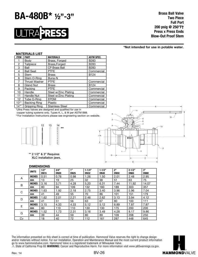
** 2 1/2” & 3” Requires XLC installation jaws.
13 1412**
MATERIALS LISTITEM PART MATERIALS ASTM SPEC.
1 Body Brass, Forged B2832 Tailpiece Brass,Forged B2833 Ball CP Brass Ball B2834 Ball Seat PTFE Commercial5 Stem Brass B1246 Stem O-Ring Buna-N7 Thrust Washer PTFE Commercial8 Gland Nut Brass B1249 Packing PTFE Commercial10 Handle Steel w/Zinc Plating Commercial11 Handle Nut Steel w/Zinc Plating Commercial12 Tube O-Ring EPDM Commercial
13** Backing Ring Plastic Commercial14** Gripping Ring Stainless Steel Commercial* Ultra Press Valves are designed and qualified for use in copper tubing systems only, Types K, L, & M per ASTM B88.
** For Installation Instructions please see engineering section on website.
DIMENSIONS
UNITS1/2”DN15
3/4”DN20
1”DN25
1-1/4”DN32
1-1/2”DN40
2”DN50
2-1/2”DN65
3”DN80
AINCHES 0.51 0.76 0.98 1.26 1.50 2.01 2.48 2.95mm 13 19 25 32 38 51 63 75
BINCHES 3.16 3.71 4.28 5.20 6.31 7.44 11.92 14.07mm 80 94 109 132 160 189 303 357
CINCHES 1.63 1.92 2.18 2.75 3.40 3.96 5.96 7.04mm 41 49 55 70 86 101 151 179
DINCHES 1.62 2.01 2.21 2.46 2.62 3.13 3.94 4.12mm 41 51 56 63 67 80 100 111
EINCHES 3.15 4.33 4.33 5.12 5.12 6.89 7.87 7.87mm 80 110 110 130 130 175 200 200
GINCHES 1.52 1.73 2.31 3.16 3.49 4.28 8.17 9.86mm 39 44 59 80 89 109 208 250
Cv 18 40 72 112 161 287 448 645
*Not intended for use in potable water.
Brass Ball ValveTwo Piece
Full Port 200 psig @ 250°F†Press x Press Ends
Blow-Out Proof Stem
BA-480B* ½”-3”

The information presented on this sheet is correct at time of publication. Hammond Valve reserves the right to change design and/or materials without notice. For our Installation, Operation and Maintenance Manual and the most current product information go to www.hammondvalve.com. Hammond Valve is a registered trademark of Milwaukee Valve.
State of California Prop 65 WARNING: Cancer and Reproductive Harm. For more information visit www.p65warnings.ca.gov.
BV-27Rev. 8
MATERIALS LISTITEM PART MATERIALS ASTM SPEC.
1 Body Brass, Forged B2832 Tailpiece Brass,Forged B2833 Ball CP Brass Ball B2834 Ball Seat PTFE Commercial5 Stem Brass B1246 Stem O-Ring Buna-N7 Thrust Washer PTFE Commercial8 Gland Nut Brass B1249 Packing PTFE Commercial10 Handle Steel w/Zinc Plating Commercial11 Handle Nut Steel w/Zinc Plating Commercial12 Tube O-Ring Plastic Commercial13 Hose Cap Polypropylene14 Cap Gasket EPDM15 Chain Brass Bead
* Ultra Press Valves are designed and qualified for use in copper tubing systems only, Types K, L, & M per ASTM B88.
DIMENSIONS
UNITS1/2”DN15
3/4”DN20
AINCHES 0.51 0.76mm 13 19
BINCHES 3.06 3.50mm 78 90
CINCHES 1.41 1.66mm 36 42
DINCHES 1.62 2.01mm 41 51
EINCHES 3.15 4.33mm 80 110
F-TUBE DIA
INCHES 0.82 0.99mm 21 25
Cv 18 40NOTE: Pressure / Temperature ratings shown are for valve only. Hose side pressure and temperature limit is based on connected hose and is the users responsibility.
Do not pressurize cap.Pressure not to exceed 40 psi.
*Not intended for use in potable water.
Brass Ball ValveTwo Piece
Full Port 200 psig @ 250°F†Press x Hose Ends
Blow-Out Proof Stem
BA-480BH* ½”-¾”
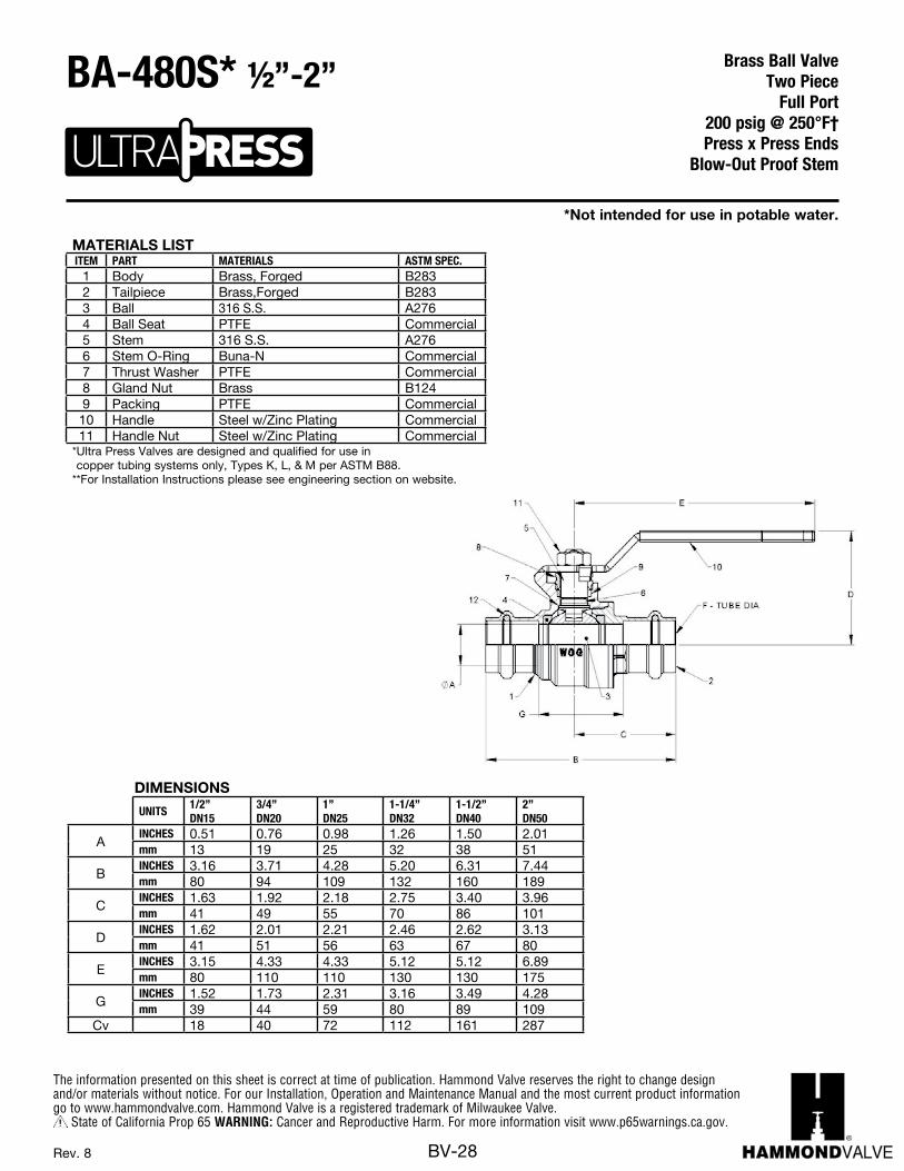
The information presented on this sheet is correct at time of publication. Hammond Valve reserves the right to change design and/or materials without notice. For our Installation, Operation and Maintenance Manual and the most current product information go to www.hammondvalve.com. Hammond Valve is a registered trademark of Milwaukee Valve.
State of California Prop 65 WARNING: Cancer and Reproductive Harm. For more information visit www.p65warnings.ca.gov.
BV-28Rev. 8
1/2" 3/4" 1" 1-1/4" 1-1/2" 2"
DN15 DN20 DN25 DN32 DN40 DN50
INCHES 0.51 0.76 0.98 1.26 1.50 2.01
mm 13 19.3 25 32 38 51
INCHES 3.16 3.71 4.28 5.20 6.31 7.44
mm 80 94 109 132 160 189
INCHES 1.63 1.92 2.18 2.75 3.40 3.96
mm 41.4 48.8 55.4 69.9 86.4 100.5
INCHES 1.62 2.01 2.21 2.46 2.62 3.13
mm 41.1 51.1 56.3 62.5 66.5 79.6
INCHES 3.15 4.33 4.33 5.12 5.12 6.89
mm 80 110 110 130 130 175
INCHES 1.52 1.73 2.31 3.16 3.49 4.28
mm 38.5 43.8 58.6 80.3 88.5 108.7
Cv 18 40 72 112 161 287
in-lb 19 58 69 89 124 210
N.m. 2.1 6.5 7.8 10 14 24
lbs. 0.46 0.84 1.16 1.88 2.82 5.52
grams 209 381 526 853 1279 2504
BA- 480S
DIMENSIONS
G
Torque
Weight
Size
A-PORTDIA
B
C
D
E
MATERIALS LISTITEM PART MATERIALS ASTM SPEC.
1 Body Brass, Forged B2832 Tailpiece Brass,Forged B2833 Ball 316 S.S. A2764 Ball Seat PTFE Commercial5 Stem 316 S.S. A2766 Stem O-Ring Buna-N Commercial7 Thrust Washer PTFE Commercial8 Gland Nut Brass B1249 Packing PTFE Commercial10 Handle Steel w/Zinc Plating Commercial11 Handle Nut Steel w/Zinc Plating Commercial
* Ultra Press Valves are designed and qualified for use in copper tubing systems only, Types K, L, & M per ASTM B88.
** For Installation Instructions please see engineering section on website.
DIMENSIONS
UNITS1/2”DN15
3/4”DN20
1”DN25
1-1/4”DN32
1-1/2”DN40
2”DN50
AINCHES 0.51 0.76 0.98 1.26 1.50 2.01mm 13 19 25 32 38 51
BINCHES 3.16 3.71 4.28 5.20 6.31 7.44mm 80 94 109 132 160 189
CINCHES 1.63 1.92 2.18 2.75 3.40 3.96mm 41 49 55 70 86 101
DINCHES 1.62 2.01 2.21 2.46 2.62 3.13mm 41 51 56 63 67 80
EINCHES 3.15 4.33 4.33 5.12 5.12 6.89mm 80 110 110 130 130 175
GINCHES 1.52 1.73 2.31 3.16 3.49 4.28mm 39 44 59 80 89 109
Cv 18 40 72 112 161 287
*Not intended for use in potable water.
Brass Ball ValveTwo Piece
Full Port 200 psig @ 250°F†Press x Press Ends
Blow-Out Proof Stem
BA-480S* ½”-2”

The information presented on this sheet is correct at time of publication. Hammond Valve reserves the right to change design and/or materials without notice. For our Installation, Operation and Maintenance Manual and the most current product information go to www.hammondvalve.com. Hammond Valve is a registered trademark of Milwaukee Valve.
State of California Prop 65 WARNING: Cancer and Reproductive Harm. For more information visit www.p65warnings.ca.gov.
BV-29Rev. 9
MATERIALS LISTITEM PART MATERIALS ASTM SPEC.
1 Body Brass, Forged B2832 Tailpiece Brass,Forged B2833 Ball 316 S.S. A2764 Ball Seat PTFE Commercial5 Stem 316 S.S. A2766 Stem O-Ring Buna-N7 Thrust Washer PTFE Commercial8 Gland Nut Brass B1249 Packing PTFE Commercial10 Handle Steel w/Zinc Plating Commercial11 Handle Nut Steel w/Zinc Plating Commercial12 Tube O-Ring Plastic Commercial13 Hose Cap Polypropylene14 Cap Gasket EPDM15 Chain Brass Bead
* Ultra Press Valves are designed and qualified for use in copper tubing systems only, Types K, L, & M per ASTM B88.
DIMENSIONS
UNITS1/2”DN15
3/4”DN20
A-PORT DIA
INCHES 0.51 0.76mm 13 19
BINCHES 3.06 3.50mm 78 90
CINCHES 1.41 1.66mm 36 42
DINCHES 1.62 2.01mm 41 51
EINCHES 3.15 4.33mm 80 110
F-TUBE DIA
INCHES 0.82 0.99mm 21 25
Cv 18 40NOTE: Pressure / Temperature ratings shown are for valve only. Hose side pressure and temperature limit is based on connected hose and is the users responsibility.
Do not pressurize cap.Pressure not to exceed 40 psi.
*Not intended for use in potable water.
Brass Ball ValveTwo Piece
Full Port 200 psig @ 250°F†Press x Hose Ends
Blow-Out Proof Stem
BA-480SH* ½”-¾”
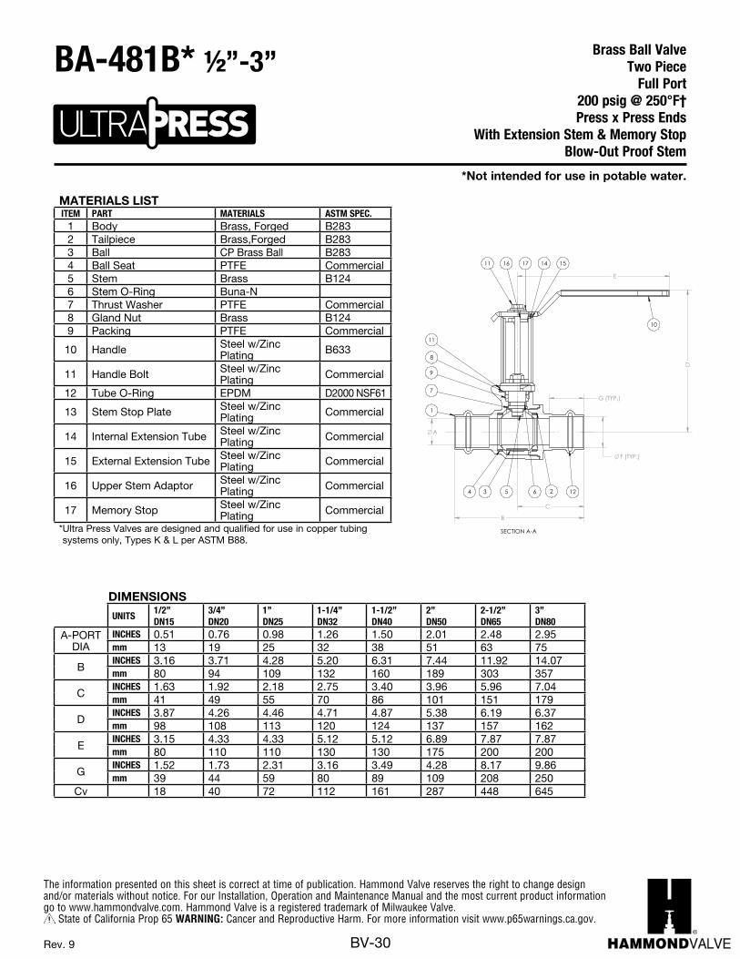
The information presented on this sheet is correct at time of publication. Hammond Valve reserves the right to change design and/or materials without notice. For our Installation, Operation and Maintenance Manual and the most current product information go to www.hammondvalve.com. Hammond Valve is a registered trademark of Milwaukee Valve.
State of California Prop 65 WARNING: Cancer and Reproductive Harm. For more information visit www.p65warnings.ca.gov.
BV-30Rev. 9
MATERIALS LISTITEM PART MATERIALS ASTM SPEC.
1 Body Brass, Forged B2832 Tailpiece Brass,Forged B2833 Ball CP Brass Ball B2834 Ball Seat PTFE Commercial5 Stem Brass B1246 Stem O-Ring Buna-N7 Thrust Washer PTFE Commercial8 Gland Nut Brass B1249 Packing PTFE Commercial
10 Handle Steel w/Zinc Plating B633
11 Handle Bolt Steel w/Zinc Plating Commercial
12 Tube O-Ring EPDM D2000 NSF61
13 Stem Stop Plate Steel w/Zinc Plating Commercial
14 Internal Extension Tube Steel w/Zinc Plating Commercial
15 External Extension Tube Steel w/Zinc Plating Commercial
16 Upper Stem Adaptor Steel w/Zinc Plating Commercial
17 Memory Stop Steel w/Zinc Plating Commercial
* Ultra Press Valves are designed and qualified for use in copper tubing systems only, Types K & L per ASTM B88.
DIMENSIONS
UNITS1/2”DN15
3/4”DN20
1”DN25
1-1/4”DN32
1-1/2”DN40
2”DN50
2-1/2”DN65
3”DN80
A-PORT DIA
INCHES 0.51 0.76 0.98 1.26 1.50 2.01 2.48 2.95mm 13 19 25 32 38 51 63 75
BINCHES 3.16 3.71 4.28 5.20 6.31 7.44 11.92 14.07mm 80 94 109 132 160 189 303 357
CINCHES 1.63 1.92 2.18 2.75 3.40 3.96 5.96 7.04mm 41 49 55 70 86 101 151 179
DINCHES 3.87 4.26 4.46 4.71 4.87 5.38 6.19 6.37mm 98 108 113 120 124 137 157 162
EINCHES 3.15 4.33 4.33 5.12 5.12 6.89 7.87 7.87mm 80 110 110 130 130 175 200 200
GINCHES 1.52 1.73 2.31 3.16 3.49 4.28 8.17 9.86mm 39 44 59 80 89 109 208 250
Cv 18 40 72 112 161 287 448 645
B
A
F (TYP.)
G (TYP.)
D
E
C
SECTION A-A
11 16 17 14 15
10
1226534
7
1
9
8
11
*Not intended for use in potable water.
Brass Ball ValveTwo Piece
Full Port 200 psig @ 250°F†Press x Press Ends
With Extension Stem & Memory StopBlow-Out Proof Stem
BA-481B* ½”-3”
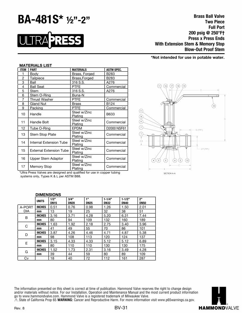
The information presented on this sheet is correct at time of publication. Hammond Valve reserves the right to change design and/or materials without notice. For our Installation, Operation and Maintenance Manual and the most current product information go to www.hammondvalve.com. Hammond Valve is a registered trademark of Milwaukee Valve.
State of California Prop 65 WARNING: Cancer and Reproductive Harm. For more information visit www.p65warnings.ca.gov.
BV-31Rev. 8
MATERIALS LISTITEM PART MATERIALS ASTM SPEC.
1 Body Brass, Forged B2832 Tailpiece Brass,Forged B2833 Ball 316 S.S. A2764 Ball Seat PTFE Commercial5 Stem 316 S.S. A2766 Stem O-Ring Buna-N7 Thrust Washer PTFE Commercial8 Gland Nut Brass B1249 Packing PTFE Commercial
10 Handle Steel w/Zinc Plating B633
11 Handle Bolt Steel w/Zinc Plating Commercial
12 Tube O-Ring EPDM D2000 NSF61
13 Stem Stop Plate Steel w/Zinc Plating Commercial
14 Internal Extension Tube Steel w/Zinc Plating Commercial
15 External Extension Tube Steel w/Zinc Plating Commercial
16 Upper Stem Adaptor Steel w/Zinc Plating Commercial
17 Memory Stop Steel w/Zinc Plating Commercial
* Ultra Press Valves are designed and qualified for use in copper tubing systems only, Types K & L per ASTM B88.
DIMENSIONS
UNITS1/2”DN15
3/4”DN20
1”DN25
1-1/4”DN32
1-1/2”DN40
2”DN50
A-PORT DIA
INCHES 0.51 0.76 0.98 1.26 1.50 2.01mm 13 19 25 32 38 51
BINCHES 3.16 3.71 4.28 5.20 6.31 7.44mm 80 94 109 132 160 189
CINCHES 1.63 1.92 2.18 2.75 3.40 3.96mm 41 49 55 70 86 101
DINCHES 3.87 4.26 4.46 4.71 4.87 5.38mm 98 108 113 120 124 137
EINCHES 3.15 4.33 4.33 5.12 5.12 6.89mm 80 110 110 130 130 175
GINCHES 1.52 1.73 2.31 3.16 3.49 4.28mm 39 44 59 80 89 109
Cv 18 40 72 112 161 287
B
A
F (TYP.)
G (TYP.)
D
E
C
SECTION A-A
11 16 17 14 15
10
1226534
7
1
9
8
11
*Not intended for use in potable water.
Brass Ball ValveTwo Piece
Full Port 200 psig @ 250°F†Press x Press Ends
With Extension Stem & Memory StopBlow-Out Proof Stem
BA-481S* ½”-2”
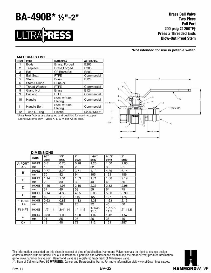
The information presented on this sheet is correct at time of publication. Hammond Valve reserves the right to change design and/or materials without notice. For our Installation, Operation and Maintenance Manual and the most current product information go to www.hammondvalve.com. Hammond Valve is a registered trademark of Milwaukee Valve.
State of California Prop 65 WARNING: Cancer and Reproductive Harm. For more information visit www.p65warnings.ca.gov.
BV-32Rev. 11
MATERIALS LISTITEM PART MATERIALS ASTM SPEC.
1 Body Brass, Forged B2832 Tailpiece Brass,Forged B2833 Ball CP Brass Ball B2834 Ball Seat PTFE Commercial5 Stem Brass B1246 Stem O-Ring Buna-N7 Thrust Washer PTFE Commercial8 Gland Nut Brass B1249 Packing PTFE Commercial
10 Handle Steel w/Zinc Plating Commercial
11 Handle Bolt Steel w/Zinc Plating Commercial
12 Tube O-Ring Plastic D2000 NSF61* Ultra Press Valves are designed and qualified for use in copper tubing systems only, Types K, L, & M per ASTM B88.
DIMENSIONS
UNITS1/2”DN15
3/4”DN20
1”DN25
1-1/4”DN32
1-1/2”DN40
2”DN50
A-PORT DIA
INCHES 0.51 0.76 0.98 1.26 1.50 2.00mm 13 19 25 32 38 51
BINCHES 2.77 3.23 3.71 4.12 4.86 6.14mm 70 82 94 105 123 156
CINCHES 1.14 1.31 1.53 1.71 1.88 2.19mm 29 33 39 43 48 56
DINCHES 1.46 1.93 2.10 2.33 2.52 2.96mm 37 49 53 59 64 75
EINCHES 3.14 4.35 4.35 5.00 5.00 6.90mm 80 110 110 127 127 175
F-TUBE DIA
INCHES 0.63 0.88 1.13 1.38 1.63 2.13mm 15 20 25 32 40 50
F1 NPT INCHES 1/2"-14 3/4"-14 1"-11.5 1-1/4"-11.5
1-1/2"-11.5 2"-11.5
GINCHES 0.83 1.00 1.00 1.02 1.42 1.57mm 21 25 25 26 36 40
Cv 18 40 72 112 161 287
*Not intended for use in potable water.
Brass Ball ValveTwo Piece
Full Port 200 psig @ 250°F†
Press x Threaded EndsBlow-Out Proof Stem
BA-490B* ½”-2”

The information presented on this sheet is correct at time of publication. Hammond Valve reserves the right to change design and/or materials without notice. For our Installation, Operation and Maintenance Manual and the most current product information go to www.hammondvalve.com. Hammond Valve is a registered trademark of Milwaukee Valve.
State of California Prop 65 WARNING: Cancer and Reproductive Harm. For more information visit www.p65warnings.ca.gov.
BV-33Rev. 6
MATERIALS LISTITEM PART MATERIALS ASTM SPEC.
1 Body Brass, Forged B2832 Tailpiece Brass,Forged B2833 Ball 316 S.S. A2764 Ball Seat PTFE Commercial5 Stem 316 S.S. A2766 Stem O-Ring Buna-N7 Thrust Washer PTFE Commercial8 Gland Nut Brass B1249 Packing PTFE Commercial
10 Handle Steel w/Zinc Plating Commercial
11 Handle Bolt Steel w/Zinc Plating Commercial
12 Tube O-Ring EPDM D2000 NSF61* Ultra Press Valves are designed and qualified for use in copper tubing systems only, Types K, L, & M per ASTM B88.
DIMENSIONS
UNITS1/2”DN15
3/4”DN20
1”DN25
1-1/4”DN32
1-1/2”DN40
2”DN50
A-PORT DIA
INCHES 0.51 0.76 0.98 1.26 1.50 2.00mm 13 19 25 32 38 51
BINCHES 2.77 3.23 3.71 4.12 4.86 6.14mm 70 82 94 105 123 156
CINCHES 1.14 1.31 1.53 1.71 1.88 2.19mm 29 33 39 43 48 56
DINCHES 1.46 1.93 2.10 2.33 2.52 2.96mm 37 49 53 59 64 75
EINCHES 3.14 4.35 4.35 5.00 5.00 6.90mm 80 110 110 127 127 175
F-TUBE DIA
INCHES 0.63 0.88 1.13 1.38 1.63 2.13mm 15 20 25 32 40 50
F1 NPT Inches 1/2"-14 3/4"-14 1"-11.5 1-1/4"-11.5
1-1/2"-11.5 2"-11.5
GINCHES 0.83 1.00 1.00 1.02 1.42 1.57mm 21 25 25 26 36 40
Cv 18 40 72 112 161 287
*Not intended for use in potable water.
Brass Ball ValveTwo Piece
Full Port 200 psig @ 250°F†
Press x Threaded EndsBlow-Out Proof Stem
BA-490S* ½”-2”
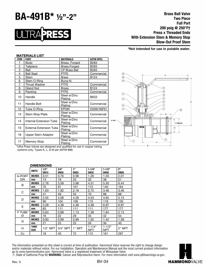
The information presented on this sheet is correct at time of publication. Hammond Valve reserves the right to change design and/or materials without notice. For our Installation, Operation and Maintenance Manual and the most current product information go to www.hammondvalve.com. Hammond Valve is a registered trademark of Milwaukee Valve.
State of California Prop 65 WARNING: Cancer and Reproductive Harm. For more information visit www.p65warnings.ca.gov.
BV-34Rev. 5
MATERIALS LISTITEM PART MATERIALS ASTM SPEC.
1 Body Brass, Forged B2832 Tailpiece Brass,Forged B2833 Ball CP Brass Ball B2834 Ball Seat PTFE Commercial5 Stem Brass B1246 Stem O-Ring Buna-N7 Thrust Washer PTFE Commercial8 Gland Nut Brass B1249 Packing PTFE Commercial
10 Handle Steel w/Zinc Plating B633
11 Handle Bolt Steel w/Zinc Plating Commercial
12 Tube O-Ring EPDM D2000 NSF61
13 Stem Stop Plate Steel w/Zinc Plating Commercial
14 Internal Extension Tube Steel w/Zinc Plating Commercial
15 External Extension Tube Steel w/Zinc Plating Commercial
16 Upper Stem Adaptor Steel w/Zinc Plating Commercial
17 Memory Stop Steel w/Zinc Plating Commercial
* Ultra Press Valves are designed and qualified for use in copper tubing systems only, Types K, L, & M per ASTM B88.
DIMENSIONS
UNITS1/2”DN15
3/4”DN20
1”DN25
1-1/4”DN32
1-1/2”DN40
2”DN50
A-PORT DIA
INCHES 0.51 0.76 0.98 1.26 1.50 2.01mm 13 19 25 32 38 51
BINCHES 2.76 3.58 3.98 4.51 5.50 6.44mm 70 91 101 115 140 164
CINCHES 1.63 1.92 2.18 2.75 3.46 3.46mm 41 49 55 70 88 88
DINCHES 3.55 4.08 4.28 4.53 4.65 5.13mm 90 104 109 115 118 130
EINCHES 3.28 4.38 4.38 4.38 6.97 6.97mm 83 111 111 111 177 177
F TUBE Ø
INCHES 0.63 0.88 1.13 1.38 1.64 2.13mm 16 22 29 35 42 54
GINCHES 0.83 0.99 0.99 1.02 1.42 1.58mm 21 25 25 26 36 40
H THRD SIZE 1/2" NPT 3/4" NPT 1" NPT 1-1/4"
NPT1-1/2" NPT 2" NPT
Cv 18 40 72 112 161 287
*Not intended for use in potable water.
Brass Ball ValveTwo Piece
Full Port 200 psig @ 250°F†
Press x Threaded EndsWith Extension Stem & Memory Stop
Blow-Out Proof Stem
BA-491B* ½”-2”

The information presented on this sheet is correct at time of publication. Hammond Valve reserves the right to change design and/or materials without notice. For our Installation, Operation and Maintenance Manual and the most current product information go to www.hammondvalve.com. Hammond Valve is a registered trademark of Milwaukee Valve.
State of California Prop 65 WARNING: Cancer and Reproductive Harm. For more information visit www.p65warnings.ca.gov.
BV-35Rev. 5
MATERIALS LISTITEM PART MATERIALS ASTM SPEC.
1 Body Brass, Forged B2832 Tailpiece Brass,Forged B2833 Ball 316 S.S. A2764 Ball Seat PTFE Commercial5 Stem 316 S.S. A2766 Stem O-Ring Buna-N7 Thrust Washer PTFE Commercial8 Gland Nut Brass B1249 Packing PTFE Commercial
10 Handle Steel w/Zinc Plating B633
11 Handle Bolt Steel w/Zinc Plating Commercial
12 Tube O-Ring EPDM D2000 NSF61
13 Stem Stop Plate Steel w/Zinc Plating Commercial
14 Internal Extension Tube Steel w/Zinc Plating Commercial
15 External Extension Tube Steel w/Zinc Plating Commercial
16 Upper Stem Adaptor Steel w/Zinc Plating Commercial
17 Memory Stop Steel w/Zinc Plating Commercial
* Ultra Press Valves are designed and qualified for use in copper tubing systems only, Types K, L, & M per ASTM B88.
DIMENSIONS
UNITS1/2”DN15
3/4”DN20
1”DN25
1-1/4”DN32
1-1/2”DN40
2”DN50
A-PORT DIA
INCHES 0.51 0.76 0.98 1.26 1.50 2.01mm 13 19 25 32 38 51
BINCHES 2.76 3.58 3.98 4.51 5.50 6.44mm 70 91 101 115 140 164
CINCHES 1.63 1.92 2.18 2.75 3.46 3.46mm 41 49 55 70 88 88
DINCHES 3.55 4.08 4.28 4.53 4.65 5.13mm 90 104 109 115 118 130
EINCHES 3.28 4.38 4.38 4.38 6.97 6.97mm 83 111 111 111 177 177
F TUBE Ø
INCHES 0.63 0.88 1.13 1.38 1.64 2.13mm 16 22 29 35 42 54
GINCHES 0.83 0.99 0.99 1.02 1.42 1.58mm 21 25 25 26 36 40
H THRD SIZE 1/2" NPT 3/4" NPT 1" NPT 1-1/4"
NPT1-1/2" NPT 2" NPT
Cv 18 40 72 112 161 287
*Not intended for use in potable water.
Brass Ball ValveTwo Piece
Full Port 200 psig @ 250°F†
Press x Threaded EndsWith Extension Stem & Memory Stop
Blow-Out Proof Stem
BA-491S* ½”-2”
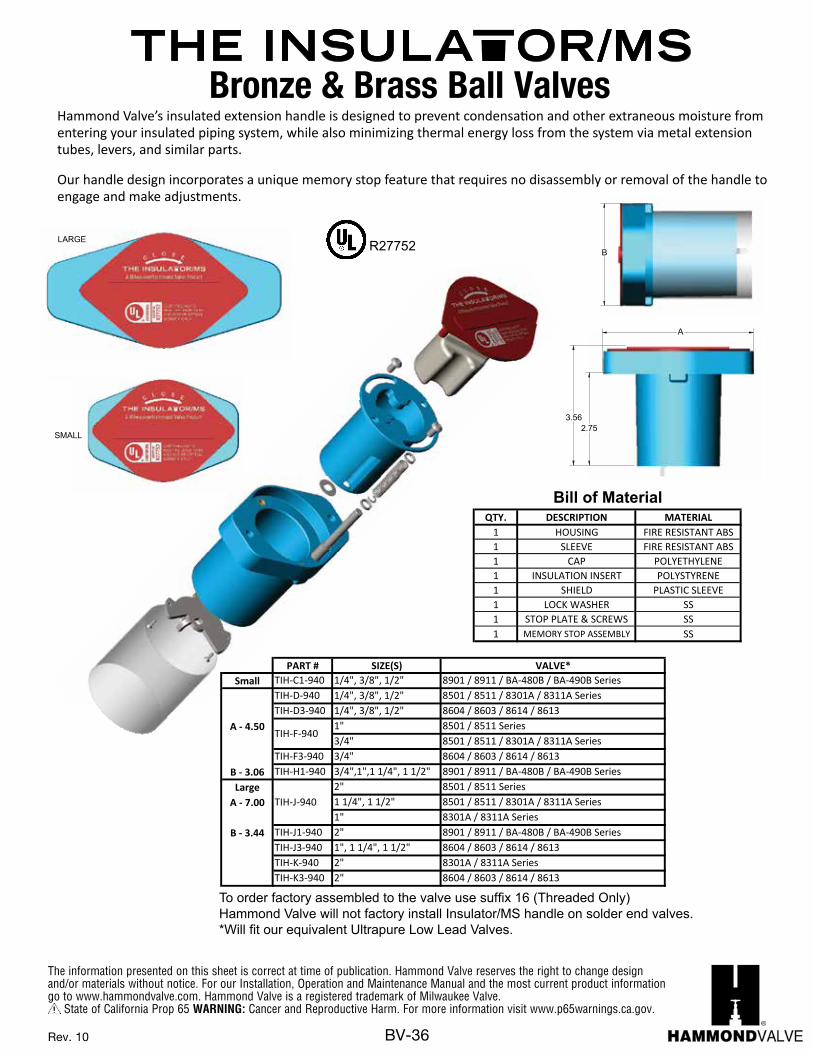
The information presented on this sheet is correct at time of publication. Hammond Valve reserves the right to change design and/or materials without notice. For our Installation, Operation and Maintenance Manual and the most current product information go to www.hammondvalve.com. Hammond Valve is a registered trademark of Milwaukee Valve.
State of California Prop 65 WARNING: Cancer and Reproductive Harm. For more information visit www.p65warnings.ca.gov.
BV-36Rev. 10
MILWAUKEE VALVE
The information presented on this sheet is correct at the time of publication. Milwaukee Valve reserves the right to changedesign, and/or material specifications without notice. For the Installation, Operation and Maintenance Manual (IOM) see theengineering section on our website. For the most current information access www.milwaukeevalve.com
NEW BERLIN, WI 53151-7301MILWAUKEE VALVE CO., INC.
DWN
CHKD
APVD
MDLD
REG APVL
TITLE
SHEET
in [mm]PRIMARY / SECONDARY
UNITS
THIS PRINT IS THE PROPERTY OF MILWAUKEE VALVE COMPANY, INC. AND REPRESENTS A PROPIETARY ARTICLE IN WHICH MILWAUKEE VALVE COMPANY, INC. RETAINS ANY
AND ALL PATENTS AND OTHER RIGHTS, INCLUDING EXCLUSIVE RIGHTS OF USE AND/OR MANUFACTURE AND/OR SALE. POSSESION OF THIS PRINT DOES NOT CONVEY ANY
PERMISSION TO REPRODUCE PRINT OR MANUFACTURE THE ARTICLE OR ARTICLES SHOWN THEREIN; SUCH PERMISSION
TO BE GRANTED ONLY BY SPECIFIC AUTHORIZATION IN WRITING, SIGNED BY AN OFFICER OR OTHER AUTHORIZED
AGENT OF MILWAUKEE VALVE COMPANY INC.
THIRD ANGLE PROJECTION
SCALE: 1:1 MASS UNITS:
INTL ECN12-472
DEPARTMENTENGINEERING
NAP8/28/13
08-27-2013 NAPPC NOREF NO
SIZE
DCAGE CODE
76364
CUT SHEET
DRAWING NO
TIH-X1 OF 1
REV
A
SMALL B
A
3.56 2.75
LARGE
13 1 SPRING SS
12 1 MS PLUNGER SS
11 2 WASHER SS
10 3 FLAT HEAD SCREW SS
9 2 BUTTON HEAD SCREW SS
8 1 RETAINING CLIP SS
7 1 STOP PLATE SS
6 1 LOCK WASHER SS
5 1 SHIELD CAB
4 1 INSULATION INSERT POLYSTYRENE
3 1 CAP POLYETHYLENE
2 1 SLEEVE FIRE RESISTANT ABS
1 1 HOUSING FIRE RESISTANT ABS
ITEM QTY. DESCRIPTION MATERIAL
REVISION HISTORY
REV DESCRIPTION ECN BY DATE CHKD
0 LARGE 3.44 7.00
TIH - K -940 2" BA-400 / BA-450 8301A/8311A
TIH - J1-940 2" BA-475 / BA-485 8901/8911
TIH - J -940
1" BA-400 / BA-450 8301A/8311A
1 1/4" , 1 1/2" BA-100 / BA-150 & BA-400 / BA-450 8501/8511 & 8301A/8311A
2" BA-100 / BA-150 8501/8511
0 SMALL 3.06 4.50
TIH - H1-9401/2" BA-475 / BA-485 8901/8911
3/4",1", 1 1/4", 1 1/2" BA-475 / BA-485 8901/8911
TIH - F -9403/4" BA-100 / BA-150 & BA-400 / BA-450 8501/8511 & 8301A/8311A
1" BA-100 / BA-150 8501/8511
TIH - D -940 1/4", 3/8", 1/2" BA-100 / BA-150 & BA-400 / BA-450 8501/8511 & 8301A/8311A
TIH - C1-940 1/4" , 3/8" BA-475 / BA-485 8901/8911
REV SIZE A B PART # SIZE(S) FITS MILWAUKEE LINE FITS HAMMOND LINE
NOTES:DIMENSIONS LISTED ARE IN ADDITION TO THE HEIGHT SHOWN IN THE CATALOG.1.DUE TO MANFACTURING PROCESSES, DIMENSIONS SHOWN ARE APPROXIMATE.2.
PART # SIZE(S) VALVE*Small TIH-C1-940 1/4", 3/8", 1/2" BA-475 / BA-485 / BA-480B / BA-490B Series
TIH-D-940 1/4", 3/8", 1/2" BA-100 / BA-150 / BA-400 / BA-450 SeriesTIH-D3-940 1/4", 3/8", 1/2" BA-300 / BA-350 Series
A - 4.50 1" BA-100 / BA-150 Series3/4" BA-100 / BA-150 / BA-400 / BA-450 Series
TIH-F3-940 3/4" BA-300 / BA-350 SeriesB - 3.06 TIH-H1-940 3/4",1",1 1/4", 1 1/2" BA-475 / BA-485 / BA-480B / BA-490B SeriesLarge 2" BA-100 / BA-150 Series
1 1/4", 1 1/2" BA-100 / BA-150/BA-400 / BA-450 Series1" BA-400 / BA-450 Series
A - 7.00 TIH-J1-940 2" BA-475 / BA-485 / BA-480B / BA-490B SeriesTIH-J3-940 1", 1 1/4", 1 1/2" BA-300 / BA-350 SeriesTIH-K-940 2" BA-400 / BA-450 Series
B - 3.44 TIH-K3-940 2" BA-300 / BA-350 Series
TIH-F-940
TIH-J-940
QTY. DESCRIPTION MATERIAL1 HOUSING FIRE RESISTANT ABS1 SLEEVE FIRE RESISTANT ABS1 CAP POLYETHYLENE1 INSULATION INSERT POLYSTYRENE1 SHIELD PLASTIC SLEEVE1 LOCK WASHER SS1 STOP PLATE & SCREWS SS1 MEMORY STOP ASSEMBLY SS
Bill of Material
R27752
To order factory assembled to the valve use suffix TIH (Threaded Only) Milwaukee Valve will not factory install (TIH) handle on solder end valves.*Will fit our equivalent Ultrapure Low Lead Valves.
Milwaukee Valve’s insulated extension handle is designed to prevent condensation and other extraneous moisture from entering your insulated piping system, while also minimizing thermal energy loss from the system via metal extension tubes, levers, and similar parts.
Our handle design incorporates a unique memory stop feature that requires no disassembly or removal of the handle to engage and make adjustments.
Rev. 7
Bronze & Brass Ball Valves
The information presented on this sheet is correct at the time of publication. Hammond Valve reserves the right to changedesign, and/or material specifications without notice. For the Installation, Operation and Maintenance Manual (IOM) see theengineering section on our website. For the most current information access www.hammondvalve.comHammond Valve is a registered trade mark of Milwaukee Valve Company.
NEW BERLIN, WI 53151-7301MILWAUKEE VALVE CO., INC.
DWN
CHKD
APVD
MDLD
REG APVL
TITLE
SHEET
in [mm]PRIMARY / SECONDARY
UNITS
THIS PRINT IS THE PROPERTY OF MILWAUKEE VALVE COMPANY, INC. AND REPRESENTS A PROPIETARY ARTICLE IN WHICH MILWAUKEE VALVE COMPANY, INC. RETAINS ANY
AND ALL PATENTS AND OTHER RIGHTS, INCLUDING EXCLUSIVE RIGHTS OF USE AND/OR MANUFACTURE AND/OR SALE. POSSESION OF THIS PRINT DOES NOT CONVEY ANY
PERMISSION TO REPRODUCE PRINT OR MANUFACTURE THE ARTICLE OR ARTICLES SHOWN THEREIN; SUCH PERMISSION
TO BE GRANTED ONLY BY SPECIFIC AUTHORIZATION IN WRITING, SIGNED BY AN OFFICER OR OTHER AUTHORIZED
AGENT OF MILWAUKEE VALVE COMPANY INC.
THIRD ANGLE PROJECTION
SCALE: 1:1 MASS UNITS:
INTL ECN12-472
DEPARTMENTENGINEERING
NAP8/28/13
08-27-2013 NAPPC NOREF NO
SIZE
DCAGE CODE
76364
CUT SHEET
DRAWING NO
TIH-X1 OF 1
REV
A
SMALL B
A
3.56 2.75
LARGE
13 1 SPRING SS
12 1 MS PLUNGER SS
11 2 WASHER SS
10 3 FLAT HEAD SCREW SS
9 2 BUTTON HEAD SCREW SS
8 1 RETAINING CLIP SS
7 1 STOP PLATE SS
6 1 LOCK WASHER SS
5 1 SHIELD CAB
4 1 INSULATION INSERT POLYSTYRENE
3 1 CAP POLYETHYLENE
2 1 SLEEVE FIRE RESISTANT ABS
1 1 HOUSING FIRE RESISTANT ABS
ITEM QTY. DESCRIPTION MATERIAL
REVISION HISTORY
REV DESCRIPTION ECN BY DATE CHKD
0 LARGE 3.44 7.00
TIH - K -940 2" BA-400 / BA-450 8301A/8311A
TIH - J1-940 2" BA-475 / BA-485 8901/8911
TIH - J -940
1" BA-400 / BA-450 8301A/8311A
1 1/4" , 1 1/2" BA-100 / BA-150 & BA-400 / BA-450 8501/8511 & 8301A/8311A
2" BA-100 / BA-150 8501/8511
0 SMALL 3.06 4.50
TIH - H1-9401/2" BA-475 / BA-485 8901/8911
3/4",1", 1 1/4", 1 1/2" BA-475 / BA-485 8901/8911
TIH - F -9403/4" BA-100 / BA-150 & BA-400 / BA-450 8501/8511 & 8301A/8311A
1" BA-100 / BA-150 8501/8511
TIH - D -940 1/4", 3/8", 1/2" BA-100 / BA-150 & BA-400 / BA-450 8501/8511 & 8301A/8311A
TIH - C1-940 1/4" , 3/8" BA-475 / BA-485 8901/8911
REV SIZE A B PART # SIZE(S) FITS MILWAUKEE LINE FITS HAMMOND LINE
NOTES:DIMENSIONS LISTED ARE IN ADDITION TO THE HEIGHT SHOWN IN THE CATALOG.1.DUE TO MANFACTURING PROCESSES, DIMENSIONS SHOWN ARE APPROXIMATE.2.
PART # SIZE(S) VALVE*Small TIH-C1-940 1/4", 3/8", 1/2" 8901 / 8911 / BA-480B / BA-490B Series
TIH-D-940 1/4", 3/8", 1/2" 8501 / 8511 / 8301A / 8311A SeriesTIH-D3-940 1/4", 3/8", 1/2" 8604 / 8603 / 8614 / 8613
A - 4.50 1" 8501 / 8511 Series3/4" 8501 / 8511 / 8301A / 8311A Series
TIH-F3-940 3/4" 8604 / 8603 / 8614 / 8613B - 3.06 TIH-H1-940 3/4",1",1 1/4", 1 1/2" 8901 / 8911 / BA-480B / BA-490B Series Large 2" 8501 / 8511 Series
A - 7.00 1 1/4", 1 1/2" 8501 / 8511 / 8301A / 8311A Series1" 8301A / 8311A Series
B - 3.44 TIH-J1-940 2" 8901 / 8911 / BA-480B / BA-490B Series TIH-J3-940 1", 1 1/4", 1 1/2" 8604 / 8603 / 8614 / 8613TIH-K-940 2" 8301A / 8311A SeriesTIH-K3-940 2" 8604 / 8603 / 8614 / 8613
TIH-F-940
TIH-J-940
QTY. DESCRIPTION MATERIAL1 HOUSING FIRE RESISTANT ABS1 SLEEVE FIRE RESISTANT ABS1 CAP POLYETHYLENE1 INSULATION INSERT POLYSTYRENE1 SHIELD PLASTIC SLEEVE1 LOCK WASHER SS1 STOP PLATE & SCREWS SS1 MEMORY STOP ASSEMBLY SS
Bill of Material
R27752
Hammond Valve’s insulated extension handle is designed to prevent condensation and other extraneous moisture from entering your insulated piping system, while also minimizing thermal energy loss from the system via metal extension tubes, levers, and similar parts.
Our handle design incorporates a unique memory stop feature that requires no disassembly or removal of the handle to engage and make adjustments.
Rev. 8
To order factory assembled to the valve use suffix 16 (Threaded Only) Hammond Valve will not factory install Insulator/MS handle on solder end valves.*Will fit our equivalent Ultrapure Low Lead Valves.
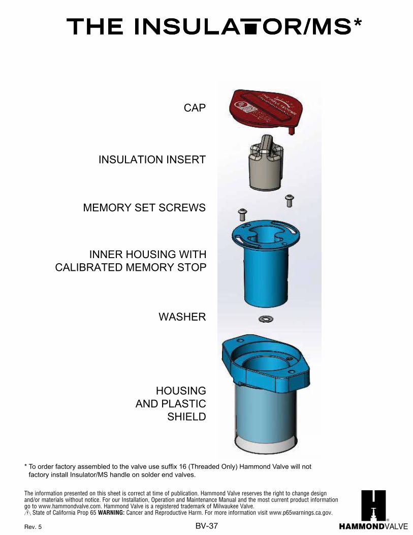
The information presented on this sheet is correct at time of publication. Hammond Valve reserves the right to change design and/or materials without notice. For our Installation, Operation and Maintenance Manual and the most current product information go to www.hammondvalve.com. Hammond Valve is a registered trademark of Milwaukee Valve.
State of California Prop 65 WARNING: Cancer and Reproductive Harm. For more information visit www.p65warnings.ca.gov.
BV-37Rev. 5
The information presented on this sheet is correct at the time of publication. Hammond Valve reserves the right to changedesign, and/or material specifications without notice. For the Installation, Operation and Maintenance Manual (IOM) see theengineering section on our website. For the most current information access www.hammondvalve.comHammond Valve is a registered trade mark of Milwaukee Valve Company.
HOUSINGAND PLASTIC
SHIELD
CAP
INSULATION INSERT
INNER HOUSING WITHCALIBRATED MEMORY STOP
WASHER
MEMORY SET SCREWS C
M
Y
CM
MY
CY
CMY
K
Isolation Handle Assembly Instructions.pdf 1 10/29/14 11:20 AM
*
* To order factory assembled to the valve use suffix 16 (Threaded Only) Hammond Valve will not factory install Insulator/MS handle on solder end valves.
Rev. 3
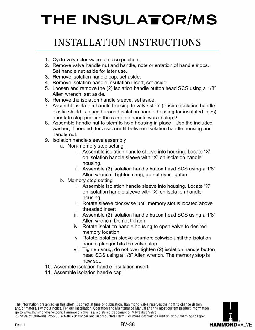
The information presented on this sheet is correct at time of publication. Hammond Valve reserves the right to change design and/or materials without notice. For our Installation, Operation and Maintenance Manual and the most current product information go to www.hammondvalve.com. Hammond Valve is a registered trademark of Milwaukee Valve.
State of California Prop 65 WARNING: Cancer and Reproductive Harm. For more information visit www.p65warnings.ca.gov.
BV-38
The information presented on this sheet is correct at the time of publication. Hammond Valve reserves the right to changedesign, and/or material specifications without notice. For the Installation, Operation and Maintenance Manual (IOM) see theengineering section on our website. For the most current information access www.hammondvalve.comHammond Valve is a registered trade mark of Milwaukee Valve Company.
INSTALLATION INSTRUCTIONS 1. Cycle valve clockwise to close position. 2. Remove valve handle nut and handle, note orientation of handle stops.
Set handle nut aside for later use. 3. Remove isolation handle cap, set aside. 4. Remove isolation handle insulation insert, set aside. 5. Loosen and remove the (2) isolation handle button head SCS using a 1/8”
Allen wrench, set aside. 6. Remove the isolation handle sleeve, set aside. 7. Assemble isolation handle housing to valve stem (ensure isolation handle
plastic shield is placed around isolation handle housing for insulated lines),orientate stop position the same as handle was in step 2.
8. Assemble handle nut to stem to hold housing in place. Use the included washer, if needed, for a secure fit between isolation handle housing and handle nut.
9. Isolation handle sleeve assembly a. Non-memory stop setting
i. Assemble isolation handle sleeve into housing. Locate “X” on isolation handle sleeve with “X” on isolation handle housing.
ii. Assemble (2) isolation handle button head SCS using a 1/8” Allen wrench. Tighten snug, do not over tighten.
b. Memory stop setting i. Assemble isolation handle sleeve into housing. Locate “X”
on isolation handle sleeve with “X” on isolation handle housing.
ii. Rotate sleeve clockwise until memory slot is located above threaded insert
iii. Assemble (2) isolation handle button head SCS using a 1/8” Allen wrench. Do not tighten.
iv. Rotate isolation handle housing to open valve to desired memory location.
v. Rotate isolation sleeve counterclockwise until the isolation handle plunger hits the valve stop.
vi. Tighten snug, do not over tighten (2) isolation handle button head SCS using a 1/8” Allen wrench. The memory stop is now set.
10. Assemble isolation handle insulation insert. 11. Assemble isolation handle cap.
Rev. 1
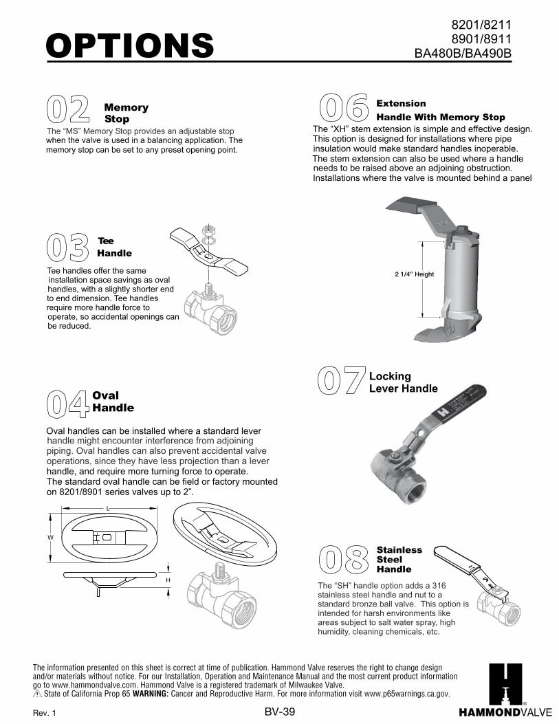
The information presented on this sheet is correct at time of publication. Hammond Valve reserves the right to change design and/or materials without notice. For our Installation, Operation and Maintenance Manual and the most current product information go to www.hammondvalve.com. Hammond Valve is a registered trademark of Milwaukee Valve.
State of California Prop 65 WARNING: Cancer and Reproductive Harm. For more information visit www.p65warnings.ca.gov.
BV-39
OPTIONS 8901/8911BA480B/BA490B
8201/8211
StainlessSteelHandle
The “SH” handle option adds a 316stainless steel handle and nut to astandard bronze ball valve. This option isintended for harsh environments likeareas subject to salt water spray, highhumidity, cleaning chemicals, etc.
The “XH” stem extension is simple and effective design.This option is designed for installations where pipeinsulation would make standard handles inoperable.The stem extension can also be used where a handleneeds to be raised above an adjoining obstruction.Installations where the valve is mounted behind a panelcan be an ideal place for the “XH” stem extension.
Extension
Handle With Memory Stop 08
MemoryStop
The “MS” Memory Stop provides an adjustable stopwhen the valve is used in a balancing application. The memory stop can be set to any preset opening point.
Height
06
LockingLever Handle07
OPTIONS 8901/8911BA480B/BA490B
8201/8211
StainlessSteelHandle
The “SH” handle option adds a 316stainless steel handle and nut to astandard bronze ball valve. This option isintended for harsh environments likeareas subject to salt water spray, highhumidity, cleaning chemicals, etc.
The “XH” stem extension is simple and effective design.This option is designed for installations where pipeinsulation would make standard handles inoperable.The stem extension can also be used where a handleneeds to be raised above an adjoining obstruction.Installations where the valve is mounted behind a panelcan be an ideal place for the “XH” stem extension.
Extension
Handle With Memory Stop 08
MemoryStop
The “MS” Memory Stop provides an adjustable stopwhen the valve is used in a balancing application. The memory stop can be set to any preset opening point.
Height
06
OPTIONS 8201/8211 8901/8911
handle might encounter interference from adjoiningpiping. Oval handles can also prevent accidental valveoperations, since they have less projection than a lever
OvalHandle
L
W
H
Oval handles can be installed where a standard lever
handle, and require more turning force to operate.The standard oval handle can be field or factory mountedon 8201/8901 series valves up to 2”.
TeeHandle
Tee handles offer the sameinstallation space savings as ovalhandles, with a slightly shorter endto end dimension. Tee handlesrequire more handle force tooperate, so accidental openings canbe reduced.
OPTIONS 8901/8911BA480B/BA490B
8201/8211
StainlessSteelHandle
The “SH” handle option adds a 316stainless steel handle and nut to astandard bronze ball valve. This option isintended for harsh environments likeareas subject to salt water spray, highhumidity, cleaning chemicals, etc.
The “XH” stem extension is simple and effective design.This option is designed for installations where pipeinsulation would make standard handles inoperable.The stem extension can also be used where a handleneeds to be raised above an adjoining obstruction.Installations where the valve is mounted behind a panelcan be an ideal place for the “XH” stem extension.
Extension
Handle With Memory Stop 08
MemoryStop
The “MS” Memory Stop provides an adjustable stopwhen the valve is used in a balancing application. The memory stop can be set to any preset opening point.
Height
06
Height2 1/4” Height
Rev. 1
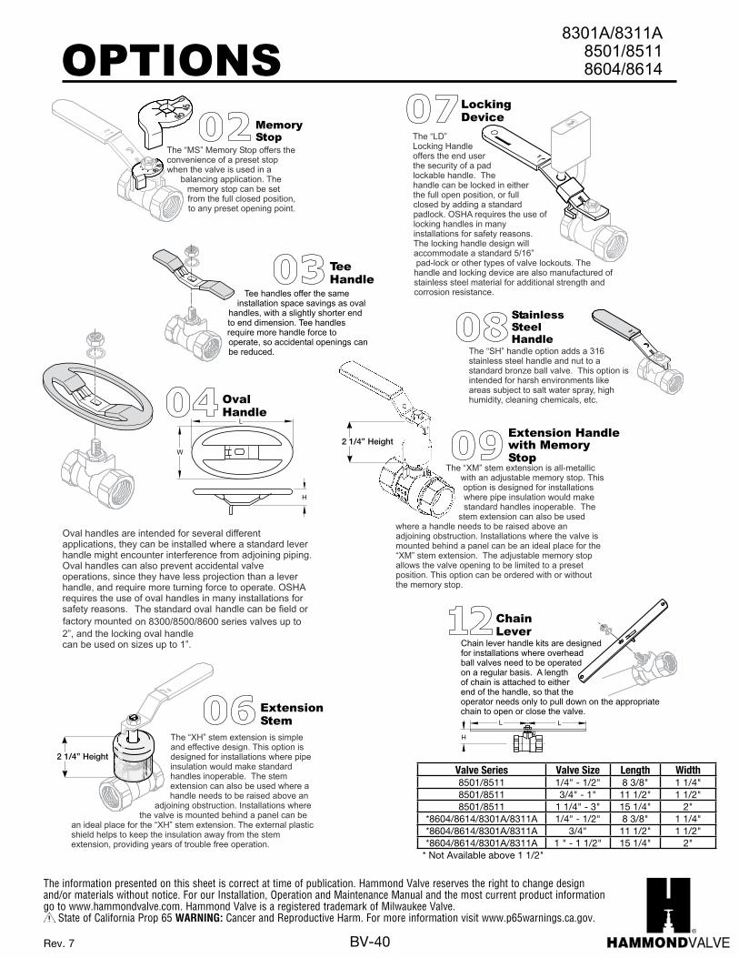
The information presented on this sheet is correct at time of publication. Hammond Valve reserves the right to change design and/or materials without notice. For our Installation, Operation and Maintenance Manual and the most current product information go to www.hammondvalve.com. Hammond Valve is a registered trademark of Milwaukee Valve.
State of California Prop 65 WARNING: Cancer and Reproductive Harm. For more information visit www.p65warnings.ca.gov.
BV-40Rev. 7
OPTIONS8301A/8303A
8501/8503
LockingOvalHandle
ChainLever
TeeHandle
H
L
W
Oval handles are intended for several differentapplications, they can be installed where a standard leverhandle might encounter interference from adjoining piping.Oval handles can also prevent accidental valveoperations, since they have less projection than a leverhandle, and require more turning force to operate. OSHArequires the use of oval handles in many installations forsafety reasons. The standard oval handle can be field orfactory mounted on 8300/8500/8600 series valves up to2”, and the locking oval handlecan be used on sizes up to 1”.
Chain lever handle kits are designedfor installations where overheadball valves need to be operatedon a regular basis. A lengthof chain is attached to eitherend of the handle, so that theoperator needs only to pull down on the appropriatechain to open or close the valve.
L
H
L
Tee handles offer the sameinstallation space savings as oval
handles, with a slightly shorter endto end dimension. Tee handlesrequire more handle force tooperate, so accidental openings canbe reduced.
OvalHandle
L
W
H
StainlessSteelHandle
The “SH” handle option adds a 316stainless steel handle and nut to astandard bronze ball valve. This option isintended for harsh environments likeareas subject to salt water spray, highhumidity, cleaning chemicals, etc.
12
08
04
04
03
8604/8603
OPTIONS
ExtensionStem
The “XH” stem extension is simpleand effective design. This option isdesigned for installations where pipeinsulation would make standardhandles inoperable. The stemextension can also be used where ahandle needs to be raised above an
adjoining obstruction. Installations wherethe valve is mounted behind a panel can be
an ideal place for the “XH” stem extension. The external plasticshield helps to keep the insulation away from the stemextension, providing years of trouble free operation.
Extension Handlewith MemoryStop
The “XM” stem extension is all-metallicwith an adjustable memory stop. Thisoption is designed for installationswhere pipe insulation would makestandard handles inoperable. The
stem extension can also be usedwhere a handle needs to be raised above anadjoining obstruction. Installations where the valve ismounted behind a panel can be an ideal place for the“XM” stem extension. The adjustable memory stopallows the valve opening to be limited to a presetposition. This option can be ordered with or withoutthe memory stop.
0
45
90
0
45
90
MemoryStop
The “MS” Memory Stop offers theconvenience of a preset stopwhen the valve is used in a
balancing application. Thememory stop can be setfrom the full closed position,to any preset opening point.
The “LD”Locking Handleoffers the end userthe security of a padlockable handle. Thehandle can be locked in eitherthe full open position, or fullclosed by adding a standardpadlock. OSHA requires the use oflocking handles in manyinstallations for safety reasons.The locking handle design willaccommodate a standard 5/16”pad-lock or other types of valve lockouts. Thehandle and locking device are also manufactured ofstainless steel material for additional strength andcorrosion resistance.
LockingDevice
09
02
06
07
8301A/8303A 8501/85038604/8603
OPTIONS
LockingOvalHandle
ChainLever
TeeHandle
H
L
W
Oval handles are intended for several differentapplications, they can be installed where a standard leverhandle might encounter interference from adjoining piping.Oval handles can also prevent accidental valveoperations, since they have less projection than a leverhandle, and require more turning force to operate. OSHArequires the use of oval handles in many installations forsafety reasons. The standard oval handle can be field orfactory mounted on 8300/8500/8600 series valves up to2”, and the locking oval handlecan be used on sizes up to 1”.
Chain lever handle kits are designedfor installations where overheadball valves need to be operatedon a regular basis. A lengthof chain is attached to eitherend of the handle, so that theoperator needs only to pull down on the appropriatechain to open or close the valve.
L
H
L
Tee handles offer the sameinstallation space savings as oval
handles, with a slightly shorter endto end dimension. Tee handlesrequire more handle force tooperate, so accidental openings canbe reduced.
OvalHandle
L
W
H
StainlessSteelHandle
The “SH” handle option adds a 316stainless steel handle and nut to astandard bronze ball valve. This option isintended for harsh environments likeareas subject to salt water spray, highhumidity, cleaning chemicals, etc.
12
08
04
04
03
8301A/8311A 8501/8511 8604/8614
OPTIONS8301A/8303A
8501/8503
LockingOvalHandle
ChainLever
TeeHandle
H
L
W
Oval handles are intended for several differentapplications, they can be installed where a standard leverhandle might encounter interference from adjoining piping.Oval handles can also prevent accidental valveoperations, since they have less projection than a leverhandle, and require more turning force to operate. OSHArequires the use of oval handles in many installations forsafety reasons. The standard oval handle can be field orfactory mounted on 8300/8500/8600 series valves up to2”, and the locking oval handlecan be used on sizes up to 1”.
Chain lever handle kits are designedfor installations where overheadball valves need to be operatedon a regular basis. A lengthof chain is attached to eitherend of the handle, so that theoperator needs only to pull down on the appropriatechain to open or close the valve.
L
H
L
Tee handles offer the sameinstallation space savings as oval
handles, with a slightly shorter endto end dimension. Tee handlesrequire more handle force tooperate, so accidental openings canbe reduced.
OvalHandle
L
W
H
StainlessSteelHandle
The “SH” handle option adds a 316stainless steel handle and nut to astandard bronze ball valve. This option isintended for harsh environments likeareas subject to salt water spray, highhumidity, cleaning chemicals, etc.
12
08
04
04
03
8604/8603
OPTIONS
ExtensionStem
The “XH” stem extension is simpleand effective design. This option isdesigned for installations where pipeinsulation would make standardhandles inoperable. The stemextension can also be used where ahandle needs to be raised above an
adjoining obstruction. Installations wherethe valve is mounted behind a panel can be
an ideal place for the “XH” stem extension. The external plasticshield helps to keep the insulation away from the stemextension, providing years of trouble free operation.
Extension Handlewith MemoryStop
The “XM” stem extension is all-metallicwith an adjustable memory stop. Thisoption is designed for installationswhere pipe insulation would makestandard handles inoperable. The
stem extension can also be usedwhere a handle needs to be raised above anadjoining obstruction. Installations where the valve ismounted behind a panel can be an ideal place for the“XM” stem extension. The adjustable memory stopallows the valve opening to be limited to a presetposition. This option can be ordered with or withoutthe memory stop.
0
45
90
045
90
MemoryStop
The “MS” Memory Stop offers theconvenience of a preset stopwhen the valve is used in a
balancing application. Thememory stop can be setfrom the full closed position,to any preset opening point.
The “LD”Locking Handleoffers the end userthe security of a padlockable handle. Thehandle can be locked in eitherthe full open position, or fullclosed by adding a standardpadlock. OSHA requires the use oflocking handles in manyinstallations for safety reasons.The locking handle design willaccommodate a standard 5/16”pad-lock or other types of valve lockouts. Thehandle and locking device are also manufactured ofstainless steel material for additional strength andcorrosion resistance.
LockingDevice
09
02
06
07
8301A/8303A 8501/85038604/8603
OPTIONS8301A/8303A
8501/8503
LockingOvalHandle
ChainLever
TeeHandle
H
L
W
Oval handles are intended for several differentapplications, they can be installed where a standard leverhandle might encounter interference from adjoining piping.Oval handles can also prevent accidental valveoperations, since they have less projection than a leverhandle, and require more turning force to operate. OSHArequires the use of oval handles in many installations forsafety reasons. The standard oval handle can be field orfactory mounted on 8300/8500/8600 series valves up to2”, and the locking oval handlecan be used on sizes up to 1”.
Chain lever handle kits are designedfor installations where overheadball valves need to be operatedon a regular basis. A lengthof chain is attached to eitherend of the handle, so that theoperator needs only to pull down on the appropriatechain to open or close the valve.
L
H
L
Tee handles offer the sameinstallation space savings as oval
handles, with a slightly shorter endto end dimension. Tee handlesrequire more handle force tooperate, so accidental openings canbe reduced.
OvalHandle
L
W
H
StainlessSteelHandle
The “SH” handle option adds a 316stainless steel handle and nut to astandard bronze ball valve. This option isintended for harsh environments likeareas subject to salt water spray, highhumidity, cleaning chemicals, etc.
12
08
04
04
03
8604/8603
OPTIONS
ExtensionStem
The “XH” stem extension is simpleand effective design. This option isdesigned for installations where pipeinsulation would make standardhandles inoperable. The stemextension can also be used where ahandle needs to be raised above an
adjoining obstruction. Installations wherethe valve is mounted behind a panel can be
an ideal place for the “XH” stem extension. The external plasticshield helps to keep the insulation away from the stemextension, providing years of trouble free operation.
Extension Handlewith MemoryStop
The “XM” stem extension is all-metallicwith an adjustable memory stop. Thisoption is designed for installationswhere pipe insulation would makestandard handles inoperable. The
stem extension can also be usedwhere a handle needs to be raised above anadjoining obstruction. Installations where the valve ismounted behind a panel can be an ideal place for the“XM” stem extension. The adjustable memory stopallows the valve opening to be limited to a presetposition. This option can be ordered with or withoutthe memory stop.
0
45
90
0
45
90
MemoryStop
The “MS” Memory Stop offers theconvenience of a preset stopwhen the valve is used in a
balancing application. Thememory stop can be setfrom the full closed position,to any preset opening point.
The “LD”Locking Handleoffers the end userthe security of a padlockable handle. Thehandle can be locked in eitherthe full open position, or fullclosed by adding a standardpadlock. OSHA requires the use oflocking handles in manyinstallations for safety reasons.The locking handle design willaccommodate a standard 5/16”pad-lock or other types of valve lockouts. Thehandle and locking device are also manufactured ofstainless steel material for additional strength andcorrosion resistance.
LockingDevice
09
02
06
07
8301A/8303A 8501/85038604/8603
2 1/4” Height
OPTIONS
ExtensionStem
The “XH” stem extension is simpleand effective design. This option isdesigned for installations where pipeinsulation would make standardhandles inoperable. The stemextension can also be used where ahandle needs to be raised above an
adjoining obstruction. Installations wherethe valve is mounted behind a panel can be
an ideal place for the “XH” stem extension. The external plasticshield helps to keep the insulation away from the stemextension, providing years of trouble free operation.
Extension Handlewith MemoryStop
The “XM” stem extension is all-metallicwith an adjustable memory stop. Thisoption is designed for installationswhere pipe insulation would makestandard handles inoperable. The
stem extension can also be usedwhere a handle needs to be raised above anadjoining obstruction. Installations where the valve ismounted behind a panel can be an ideal place for the“XM” stem extension. The adjustable memory stopallows the valve opening to be limited to a presetposition. This option can be ordered with or withoutthe memory stop.
0
45
90
045
90
MemoryStop
The “MS” Memory Stop offers theconvenience of a preset stopwhen the valve is used in a
balancing application. Thememory stop can be setfrom the full closed position,to any preset opening point.
The “LD”Locking Handleoffers the end userthe security of a padlockable handle. Thehandle can be locked in eitherthe full open position, or fullclosed by adding a standardpadlock. OSHA requires the use oflocking handles in manyinstallations for safety reasons.The locking handle design willaccommodate a standard 5/16”pad-lock or other types of valve lockouts. Thehandle and locking device are also manufactured ofstainless steel material for additional strength andcorrosion resistance.
LockingDevice
09
02
06
07
8301A/8303A 8501/85038604/8603
2 1/4” Height
Valve Series Valve Size Length Width8501/8511 1/4" - 1/2" 8 3/8" 1 1/4"8501/8511 3/4" - 1" 11 1/2" 1 1/2"8501/8511 1 1/4" - 3" 15 1/4" 2"
*8604/8614/8301A/8311A 1/4" - 1/2" 8 3/8" 1 1/4"*8604/8614/8301A/8311A 3/4" 11 1/2" 1 1/2"*8604/8614/8301A/8311A 1 " - 1 1/2" 15 1/4" 2"
* Not Available above 1 1/2"