brochure - ubs industries · brochure. welding & painting guidelines . for galvanized steel...
TRANSCRIPT

A PART OF
BROCHURE
WELDING & PAINTING GUIDELINES FOR GALVANIZED STEEL TUBEWelding Processes • Safety Practices • Painting & Powder Coating

2
Welding and Painting
TABLE OF CONTENTS
Page 2 ..............................3 Welding Rules for Quality Results
Page 2 .......................................................................Disclaimer
Page 3 ................................................ Sound Welding Practice
Pages 3-4 ....................................................Welding Processes Gas Metal Arc (MIG) Welding/
Shielded Metal Arc (stick) Welding/ Gas Tungsten Arc (TIG or Heliarc) Welding
Pages 4-5 ............................................Proper Safety Practices Welding Smoke and Fumes/
Electrical Shock/ Electromagnetic Radiation
Page 5 .............................................Welding Process Glossary
Page 6 ............................... Allied’s Triple Coating Description/Corrosion Protection Methods
Page 7 ............................Corrosion Resistant Touch-up Paint/Painting/Powder Coating over
Allied’s Galvanized Tube Surface
DISCLAIMERThe specifications, descriptions, information and illustrated material herein is not intended nor should it be relied upon to provide anyone with all of the relevant information required for welding/painting Allied Tube & Conduit Corporation’s galvanized steel tubing. The material is submitted solely for evaluation by others and Allied Tube & Conduit Corporation assumes no responsibility whatsoever for its accuracy or application. Reference should be made to original or primary source data along with standard accepted industry practice. The material herein is as the date of publication and is subject to change without notice.
Welding Allied Tube & Conduit Corporation’s
Galvanized Steel Tubing is a very achievable
operation if three key points are observed
to assure consistent, quality results...
• Use of sound welding practice
and procedures
• Proper safety practices
• Application of good weld
corrosion protection methods

3
SOUND WELDING PRACTICETubular steel should be welded so as to develop the adequate strength at all connections between tubes; accordingly, the required weld configuration and size should be specified on the drawings by the designer. When tubes are butt welded (i.e., joined end-to-end), the weld should penetrate through the full tube wall thickness and reinforcement should not exceed 3/32 inches (2.5 mm).
When the joint design is a tee, corner or fillet weld, the size and length required should be shown on the drawing. For the convenience of the designer, the following weld sizes will provide welds that have a throat dimension that is at least equal to the thickness of the tube being joined. When tubes of different wall thicknesses are joined, the minimum fillet weld size can be based on the thinner of the members.
Tube Wall Minimum Fillet Tube Wall Minimum Fillet
Thickness(in.) Weld Size Thickness(in.) Weld Size
0.035 0.063 (1/16”) 0.113 0.160 (3/16”)
0.049 0.069 (3/32”) 0.133 0.186 (3/16”)
0.065 0.092 (3/32”) 0.140 0.198 (7/32”)
0.072 0.102 (1/8”) 0.145 0.205 (7/32”)
0.083 0.117 (1/8”) 0.154 0.217 (7/32”)
0.095 0.134 (5/32”) 0.180 0.250 (1/4”)
0.109 0.134 (5/32”) any wall 1.414 X (t)
thickness(t)
These fillet weld sizes are suitable for tee and angle joints where the tube end is coped to match the outside diameter of the mating tube or where the tube end is flattened so that contouring is not needed. The numbers in parentheses are the nearest larger fraction of the required weld size and match standard fillet gauge sizes.
While there is no maximum fillet size, oversized welds do not make the weld perform better. Additionally, it takes more time to make oversized welds and this costs money.
Completed welds should be visually examined and exhibit no gaps, voids, cracks, undercut, porosity or arc strikes; they should be reasonably smooth and uniform. Weld spatter should be removed particularly if the surface being welded will be restored by painting or coating.
Fillet welds sizes should be verified using a fillet weld gauge. These are simple go-no go gauges that can be purchased from your local welding supplier, or they can be machined from heavy sheet metal for specific sizes. Where the drawing specifies welding all around a joint, the weld size should meet minimum drawing requirements all around the joint.
Fillet weld gauges should be used in the following manner:
The gauge must touch weld metal before touching the base metal. Where it is difficult to actually measure the entire weld due to the geometry of the members, measure the weld at the nearest measurable point. Then visually check that it is the same width all around.
WELDING PROCESSESGAS METAL ARC (MIG) WELDINGThis is by far the most widely used process when welding Allied Tube & Conduit® Corporation’s tube, because it makes high-quality welds quickly.
The first choice is to use the Spray Transfer mode. Use 0.035 inch ER70S-2 or ER70S-3 wire, 92% Argon/8% CO2 shielding gas, a welding gun rated at 400 amps or more and a power source rated at 400 amps, 100% duty cycle. Follow the table below. Travel speed will be high and deposition rates (i.e. production rate) will be high.
Thickness Wire Feed Gauge (inches) Voltage Amps Speed (ipm)
7 0.180 18 125/140 170/210
10 0.135 18 125 170
12 0.105 17 115 160
14 0.075 17 110 155
16 0.059 17 100 140
18 0.047 16 90 130
20 0.035 16 60 70
22 0.028 15 65 55
When welding 16 gauge and thinner galvanized steel, it may be necessary to use the short circuiting transfer mode. The power source should be rated at 200 amps or more at 100% duty cycle, and it should have “inductance” control. Use 0.035 inch ER70S-2 or ER70S-3 wire, 92% Argon/8% CO2 shielding gas, a welding gun rated at 300 amps. Set the inductance to maximum and the slope control (if any) between mid-range and maximum slope. Follow the settings in the table below.
If the welder has difficulty keeping the stickout constant, switch to 0.030 inch diameter wire and adjust the wire feed speed to use approximately the amperage shown above.
Spray Transfer Short Circuiting
Volts: 27 to 30 17 to 20
Amps: 250 to 380 100 to 190
Wire Feed Speed (ipm): 280 to 450 100 to 210
Dial Location (o’clock): 1 to 3 9 to 11
Tip position: Recessed 1/4 inch Extended 1/4 in
Wire Stick-out: 3/4 in 3/8 in
Gas flow rate: 25 to 30 CFH 25 to 30 CFH
Spatter indicates that: Arc voltage too low Arc voltage too high

4
Welding and Painting
The wire stickout should be held constant during welding. If the welder pulls the torch away from the workpiece, the stickout gets longer and the arc voltage will increase causing spatter, if the welder is using short circuiting transfer. If the welder brings the torch closer to the workpiece, the stickout gets shorter, reducing the voltage across the arc and increasing spatter, if the welder is using spray transfer. Welders should understand these facts; the welder needs to get the voltage settings right (i.e., set it for minimum spatter) and also be aware that increasing or decreasing the stickout affects the voltage across the arc and the amount of spatter that is developed. One of the best training resources for GMAW can be found at:
http://www.weldreality.com/eds_training_materials.htm
Some fabricators have had success welding galvanized tube using E70C-6 metal cored wire such as Hobart’s Galvacor; the parameters given above are a good starting point for metal cored wire. Others have found that self-shielded flux cored wire conforming to E71T-14, such as Lincoln’s Innershield NR-152 and ESAB’s CoreShield 10 perform well for some work since a shielding gas is not needed. Follow the electrode manufacturer’s recommended settings with flux cored wire.
Shielding gas
The above recommends starting with a shielding gas of 92% argon/8% CO2. If welding on tube that is 12 gauge in thickness, or to thick parts, the CO2 can be increased to as much as 18%. This increases the arc energy, ensuring penetration into thicker steel. Conversely, if you are welding 18 gauge or thinner, the CO2 can be reduced to 2%. If burn-through is a problem, switch to 98% Argon/2% Oxygen gas mixture and reduce the voltage by 2 to 3 volts. Use of Argon/Oxygen mixtures is not recommended for tube thicknesses over 1/8 inch.
A gas that develops noticeably less zinc fume when welding galvanized tube is Praxair’s Helistar® GV; however, since it is a helium/argon/CO2 mixture, it is more expensive than argon-based shielding gas.
SHIELDED METAL ARC (STICK) WELDINGDue to its low productivity, this process should be used where GMAW cannot be used, such as outdoors where wind would make use of a gas-shielded process impractical. Allied Tube & Conduit Corporation’s galvanized steel tube can be welded using 3/32 inch diameter E6013 electrode with direct current and electrode positive (reverse polarity) or alternating current and the parameters recommended by the electrode manufacturer. When welding tube to thicker materials, E6010 should be used to ensure penetration into the thicker material.
GAS TUNGSTEN ARC (TIG OR HELIARC) WELDINGThis process also has low productivity but can make very sound welds between galvanized components. Welding of thinner gauge galvanized steel can be done using direct current, electrode negative (straight polarity), 1/16” diameter EWTh-2 tungsten pencil-sharpened with a 1/32” flat end, ER70S-2 or ER70S-3 filler metal, argon shielding gas and the following parameters:
Gauge Thickness (in.) Amps for Amps for Filler Dia. Grooves Fillets (in.)
18 to 22 0.028 to 0.047 35 to 65 40 to 60 1/16 or 3/32
14 & 16 0.059, 0.075 45 to 75 65 to 90 3/32
12 0.105 65 to 90 95 to 105 3/32
10+ 0.135 70 to 100 110 to 130 3/32
GTAW is the slowest and costliest of the welding processes, and it should be used only where visual appearance is critical and mechanical surface treatment for appearance is not practical.
PROPER SAFETY PRACTICESWhen a manufacturer uses welding, it needs to be aware of safety hazards associated with welding. These include Welding Smoke and Fumes, Electrical Shock, and Electromagnetic Radiation.
WELDING SMOKE AND FUMESWelding produces smoke and fumes which come up from the weld zone in what is referred to as a plume. Obviously, the smoke and fumes which result from welding are not especially healthy to breathe!
The most-cost effective thing a company with welding fumes and smoke can do is to teach its welders to keep their heads out of the fume plume. Supervisory personnel should be instructed to watch for welders whose heads are in the plume and advise them to change positions. Welders should set up their work so that air flows from one side to the other, rather than towards or from behind the welder.
This will keep the plume (and its contents) away from the welder’s breathing zone. When there is a ceiling height of 16 feet or more, and a space of 10,000 cubic feet per welder, and no confined spaces, natural ventilation is considered adequate. When these criteria are not met, forced ventilation must be provided according to American National Standards Institute (ANSI) standard Z49.1*.
This may be done by using a mobile hood or exhaust hose which can be placed in the vicinity of welding, or by using a fixed enclosure which will provide an air flow rate of 100 feet per minute (1 to 2 MPH) in the vicinity of welding. Ventilation can also be in the form of open grid work tables with uniform downdraft ventilation providing at least 150 cubic feet of air per minute per square foot of table surface. Finally, a low volume, high-velocity fume eductor may be attached to the welding gun to provide local fume removal.

5
WELDING PROCESS GLOSSARYArc welding is the most widely used form of welding. In arc welding, heat is created by an electric arc between an electrode and the material to be welded. The heat melts the metal which must be shielded from the atmosphere. If unwanted gases mix with the molten metal, oxides and porosity form, decreasing the metal’s soundness and strength.
The five common arc-welding processes and several others are listed below. Each process is distinguished by its own means of shielding the weld pool and adding filler metal.
Gas Metal Arc Welding (GMAW) also called MIG welding, uses equipment which pushes wire and shielding gas through a welding gun. Mixtures of argon and carbon dioxide are used to shield steels while argon is used to shield nonferrous metals. This process is widely used for welding Allied Tube & Conduit Corporation’s products.
Flux Cored Arc Welding (FCAW) is exactly the same as GMAW, except that it uses a tubular electrode containing flux instead of solid wire. This process produces a fast and clean weld with excellent properties.
Shielded Metal Arc Welding (SMAW) is entirely controlled by hand. A consumable, coated electrode gives off a gas which forms a shield around the molten weld metal. This welding is suitable for steels, iron and many nonferrous metals.
Gas Tungsten Arc Welding (GTAW), also know as TIG and Heli-arc welding, uses a tungsten electrode to carry the arc. The weld pool is shielded by helium or argon gas. This process is used mainly on thinner metals, but it can be used for welding all metals.
Submerged Arc Welding (SAW) uses a flux in the form of a coarse, granular mixture of minerals which is placed on the workpiece ahead of the welding electrode. The arc is completely covered by the flux during welding. Submerged arc welding is usually used for welding of thick materials.
Resistance Welding (RW) welds material by passing current through overlapping work pieces. The interface between the faying surfaces provides the greatest resistance to current flow, resulting in heat concentration and welding at that point. The work pieces must be clamped together, so access to both sides of the parts to be joined is necessary. This process is usually automated. Spot welding and seam welding are two types of resistance welding.
Oxy-Fuel Welding (OFW) is done by burning oxygen and acetylene to make a flame. Gas welding is slow compared to arc welding.
Laser-Beam Welding (LBW) produces a weld using a high-intensity beam of coherent light. The result is a narrow, smooth and clean weld with a small heat-affected zone. Laser-beam welding works well on steels.
Electron-Beam Welding (EBW) uses a beam of electrons to make a clean, deep weld between closely-fitted parts. The beam itself melts the metal, and welding is usually done in a deep vacuum.
Stud Welding (SW) is done by placing a stud in a welding gun, placing the gun at the desired location and pulling the trigger. An arc is initiated between the end of the stud and the surface, and in less than a second, the stud is attached. Studs are usually less than 3/8 inch in diameter.
The USFDA recognizes that at least 15 mg/day of zinc is essential for proper health in humans. Zinc is also a necessary micronutrient for plant and animal life. Too much zinc, however, can cause temporary illness known as “metal fume fever.” Inhaling the white zinc oxide which is produced when welding zinc may cause temporary symptoms of influenza, including fever and chills. No permanent or long-term effects are known to occur. It is important that the welding plume containing the zinc oxide be carried away from the welder.
ANSI Z49.1* requires that zinc fume removal be done by local exhaust ventilation when zinc is welded indoors. Welders should also be taught not to stand or work downwind from another welder who is welding on zinc coated materials. In addition to local or general ventilation, personal breathing filters are recommended. Light-weight, disposable, half-face filters such as the 3M™ Welding Fume Respirator or the Dust/Fume/Mist filter (#9920) are convenient for the welder, and no maintenance is required. Half-face mask cartridge filters using filter elements designed for metal fume removal are also acceptable. Powered air purifying systems and supplied air systems such as the 3M™ Adflo™ Powered Air Purifying Respirator (PAPR) are also available. These systems provide combined respiratory, head, eye and face protection for situations in which fume exposure cannot be avoided.
*This Standard as well as Welding Safety and Health Fact Sheets are available free from the American Welding Society, Miami, Florida at http://www.aws.org/safety/index.html.ELECTRICAL SHOCKWelders and those who work around welding need to be aware that there is sufficient voltage in a welding circuit to cause severe injury. When using a standard arc welding machine, there is 80 volts of difference between the welding electrode and the surrounding work piece and building; when using a continuous wire process, such as MIG or Flux core, this difference is around 40 volts. Welders are usually aware of the potential hazard, but others who work around welding are frequently unaware of this danger. This situation should be regularly addressed during safety meetings.
ELECTROMAGNETIC RADIATIONWhen using any arc welding process, an electrical arc is generated which emits various forms of electromagnetic radiation energy, including light. The most harmful of this radiation is ultraviolet light which can cause blindness with excessive exposure. Welders know to wear adequate protection from radiation when they are welding. Those who work around welding, however, must also protect themselves. This is usually done by placing either opaque or translucent but ultraviolet absorbing barriers around the area where welding is being done. This radiation can also burn skin, so the welder and those who work around welding should wear protective clothing to avoid the hazard. Eye protection should consist of wearing polycarbonate safety glasses with side shields.
Polycarbonate absorbs the most harmful ultraviolet radiation, preventing eye damage. In addition, this practice will prevent “Welding Flash Burn” (sunburn of the white of the eyeball), which is usually caused by reflection of the arc from surrounding objects, including walls.
6
Welding and Painting
CORROSION PROTECTION METHODSWhen welding galvanized tubing, it is important to restore the corrosion resistance of the weld zone to that of the surrounding parent surface areas. This can be accomplished in a few easy steps...
1. Clean the weld area using a wire brush to remove slag and loose particulate...wipe away dust with clean, dry rag. Surface must be clean and oil-free.
2. It is recommended that the weld zone be treated with one or two coats of a cold galvanizing compound. Follow the manufacturer’s label directions for best results.
3. If the welded assembly will be powder coated, follow through step 2, making sure a heat-resistant cold galvanizing compound is used to withstand the baking temperature and cycle time. This will ensure proper adhesion and minimize outgassing. For more information on how to obtain a heat-resistant cold galvanizing compound that also acts as a primer for powder coating, contact your local sales representative or the mechanical tube division for more specific information.
4. If the welded assembly is to be liquid painted, follow through step 2; then we suggest that a high quality urethane-based top-coat paint be used for superior corrosion protection.
5. If the assembly will not be painted, follow through step 2 above. Then, in the weld zone, use a corrosion resistant touch up paint, as available from Allied Tube & Conduit Corporation, to tone match this area with the surrounding galvanized surfaces, again following label directions. (See following section for details.)
TRIPLE COATING DESCRIPTIONZINC COATINGZinc melts at 787°F, then boils at 1665°F, becoming a vapor and, as it mixes with oxygen in the air, changes to zinc oxide. Zinc oxide is normally visible as about 30% of the white plume rising from the welding point. As has been already stated, proper safety precautions should be followed when welding with any zinc coated tube product.
CONVERSION COATINGIn Allied Tube & Conduit Corporation’s process, the conversion coating on the zinc substrate is particularly thin, and as it relates to the welding process, may be considered negligible.
ORGANIC COATINGAllied Tube & Conduit Corporation’s tube is additionally protected by a clear organic top coat. In welding, this organic top coat could generate fumes irritating to the welder if proper ventilation procedures are not followed. Removal of this coating is recommended and easily accomplished. The tube should be cleaned back from the end to be welded: a minimum of 2” for arc welding, 4” for gas welding. Sand with flapper wheel or by hand (3M “Scotch-Brite” or Norton “Beartex” unitized abrasive wheels suggested). Personal breathing filters are recommended to avoid inhalation of dust and related coating particulate. Wire brushing and grinding wheels are not effective.
Material Safety Data Sheets on Allied Tube & Conduit Corporation’s galvanized tubular products are available on request from your local sales representative.
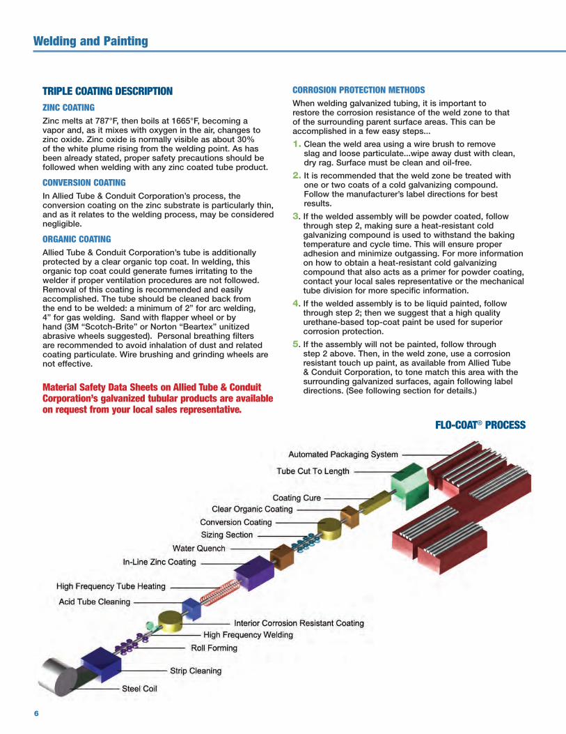
FLO-COAT® PROCESS

7
PAINTING OVER ALLIED TUBE & CONDUIT CORPORATION’S GALVANIZED STEEL TUBINGIt’s easy to paint or powder coat over our galvanized steel tubing.
Simple surface cleaning of the tube is required due to normal transportation and storage related accumulated soils. Merely wipe off such soils with a mild cleaning solution. This will eliminate or minimize outgassing.
Our galvanized steel tube coatings will also withstand in-line chemical cleaning baths and rinses. At the same time, our coatings will not damage or contaminate any part of your cleaning system.
Allied Tube & Conduit Corporation’s galvanized tube products are protected by a clear organic top coating which provides excellent outer-coat adhesion to most thermo-set powder coatings, as well as to the following air dry and bake topcoats:
• High-bake thermoset acrylic
• High-bake alkyd
• High-bake polyester
• Two-part urethane or epoxy
• Solvent-based paints for metals
• Solvent-based paints for wood
• Solvent-based high-solids paints
• Oil-based paints
• Paints for car bodies or appliances
As you can see, almost all powder or liquid paints will work well over our clear topcoat. If the paint/powder coating you are using does not fall into one of the above categories, or you have any questions, please contact Allied Tube & Conduit Corporation’s Mechanical Tube Division for more specific information.
CORROSION RESISTANT TOUCH-UP PAINTAllied Tube & Conduit Corporation has a corrosion resistant, color matching touch-up paint available for its zinc product varieties.
Here are the facts about this touch up paint:
1. Excellent color match to Allied Tube & Conduit Corporation’s zinc finish
2. Superior adhesion
3. Available in aerosol spray cans
4. Dry time: 10 minutes
5. Shelf life: 2 years
Material Safety Data Sheets for aerosol spray cans are available from your local sales representative upon request.

16100 South Lathrop Avenue
Harvey, IL 60426
TOLL-FREE / 800-882-5543
FAX / 708-339-2399
www.atc-mechanical.com
©2015 Atkore International, Inc. All rights reserved. ATCM-L-1493-1502
®