brochure-pvc gasket pipe
DESCRIPTION
Brochure-PVC Gasket PipeTRANSCRIPT

HPB-160Effective 12/30/10
PVCGasket
Pipe
Low assembly force enables fast and simplefield installation without the risk of gasketdislocation. Each spigot end of Harvel gasketpipe contains a 15° bevel for easy insertion,as well as a factory-placed reference markto indicate proper insertion depth. The
reference marks also provide a visual meansto verify proper insertion if lines are assem-bled above ground, and lowered into thetrench after assembly. Field-cut lengths mustbe cut square, beveled to the same 15° taper,and marked to the proper insertion depth(see Table I).
DeflectionHarvel gasketed joints permit an angulardeflection of 2° at the joint. Adequatedeflection can usually be achieved for gentlecurves by using the inherent flexibility of thepipe itself, without using joint deflection.
Thrust BlockingAll gasket-joint piping requires adequatethrust restraints to prevent movement fromforces generated by changes in direction,valve operation, dead ends, reduction in pipesize, and other areas where thrusts can bedeveloped. The size and type of thrustrestraint depends on the pipe size, type offitting, soil properties, and water-hammerpossibilities. Keeping flow velocities at orbelow 5 ft/sec will help minimize surgepressures. Fittings and valves used to makevertical changes in direction should beanchored to the thrust restraint to preventoutward and upward thrusts at the fittingjunctures. In pressure lines, valves 3" indiameter and larger should be anchored to
• Fast, Leak-Free Installation• Low Assembly Force• Positive Seal• Integral Gasket Design
Prevents Gasket Dislocation
PVCGasket
Pipe
A B C 15°
D E
TABLE I:Gasket Pipe Dimensions
0.5900.6700.708
0.8671.0631.260
1.8752.0002.125
2.2502.5002.7502.203
A
221/2
3
468
101214
16182024
IPS(in.)
1.3291.4891.587
1.7232.0762.073
2.4172.6193.375
2.8753.0623.3753.781
B
2.8202.8602.940
3.0203.2003.500
4.7505.5006.000
6.5007.0007.3758.000
C
4.7395.0195.235
5.6106.3396.833
9.04210.11911.500
11.62512.56213.50013.984
D
0.4740.5660.688
0.8741.2741.500
1.5001.5001.500
1.5001.5001.5001.500
E(approx.)
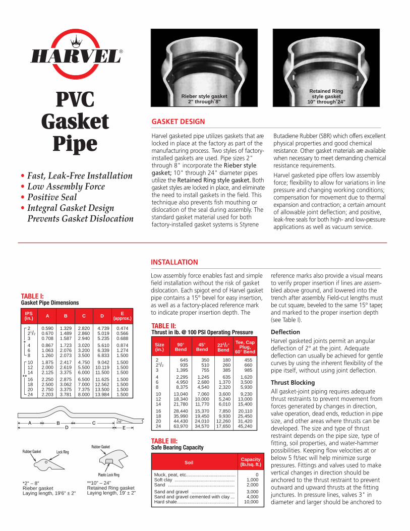
Harvel gasketed pipe utilizes gaskets that arelocked in place at the factory as part of themanufacturing process. Two styles of factory-installed gaskets are used. Pipe sizes 2"through 8" incorporate the Rieber stylegasket; 10" through 24" diameter pipesutilize the Retained Ring style gasket. Bothgasket styles are locked in place, and eliminatethe need to install gaskets in the field. Thistechnique also prevents fish mouthing ordislocation of the seal during assembly. Thestandard gasket material used for bothfactory-installed gasket systems is Styrene
Butadiene Rubber (SBR) which offers excellentphysical properties and good chemicalresistance. Other gasket materials are availablewhen necessary to meet demanding chemicalresistance requirements.
Harvel gasketed pipe offers low assemblyforce; flexibility to allow for variations in linepressure and changing working conditions;compensation for movement due to thermalexpansion and contraction; a certain amountof allowable joint deflection; and positive,leak-free seals for both high- and low-pressureapplications as well as vacuum service.
Retained Ringstyle gasket
10" through 24"Rieber style gasket
2" through 8"
TABLE II:Thrust in lb. @ 100 PSI Operating Pressure
455660985
1,6203,5005,930
9,23013,00015,400
20,11025,45031,42045,240
Tee, CapPlug,
60° Bend
180260385
6351,3702,320
3,6005,2406,010
7,8509,930
12,26017,650
221/2°Bend
350510755
1,2452,6804,540
7,06010,00011,770
15,37019,45024,01034,570
45°Bend
645935
1,395
2,2954,9508,375
13,04018,34021,780
28,44035,99044,43063,970
90°Bend
221/2
3
468
101214
16182024
Size(in.)
TABLE III:Safe Bearing Capacity
Muck, peat, etc......................................Soft clay ..............................................Sand ...................................................
Sand and gravel .................................Sand and gravel cemented with clay ...Hard shale............................................
01,0002,000
3,0004,000
10,000
SoilCapacity(lb./sq. ft.)
GASKET DESIGN
INSTALLATION
**10" – 24"Retained Ring gasketLaying length, 19' ± 2"
Rubber Gasket
Plastic Lock Ring
Lock Ring
*2" – 8"Rieber gasketLaying length, 19'6" ± 2"
Rubber Gasket
®

the thrust restraint to prevent movementwhen operated. Consideration should alsobe given for the proper support, anchoring,and thrust restraint for lines installed onslopes. Refer to Table II for pounds of thrustdeveloped for various fittings, and to TableIII for safe bearing capacities of typical soils.
The size of thrust block required (in squarefeet) can be determined by dividing the totalthrust developed (in psi) by the capacity ofthe soil (in pounds/square foot).
The most common method of thrustblocking involves the pouring of concrete(to the size of block required) between thepipe fitting and the bearing wall of thetrench. Mechanical thrust restraint devicesare also used, but must be of design for usewith PVC pipe.
Trenching: Initial BackfillTrench depth is determined by the intendedservice and local conditions. Harvel gasketpipe should be buried a minimum of 12"below frost line in areas subject to freezing,or a minimum depth of 18 to 24 incheswhere there is no frost. Permanent linessubjected to heavy traffic should have aminimum cover of 24". In areas not subjectto freezing, a minimum cover of 12 to 18inches is usually sufficient for small-diameterpiping subjected to light traffic. Bearingstresses must be calculated to determine
the amount of cover required. Reference toapplicable local, state, or national codes isalso recommended.
The trench bottom should be continuous,relatively smooth, and free of rocks anddebris. Adequate backfill should be in placeimmediately after installation, prior to fillingor testing the line, to help distribute theeffects of expansion/contraction evenly overeach pipe length. The initial backfill materialshould consist of particles of 1/2" in size orless, and properly tamped. Generally aminimum of 6 to 12 inches of backfill isdesirable for the initial phase. Wherehardpan, ledge rock, or large boulders areencountered, the trench bottom should bepadded with sand or compacted fine-grainsoils to provide adequate protection. Jointsshould be left exposed for visual inspectionduring testing.
TestingIf separate tests are to be conducted forpressure and leakage, pressure testing shouldbe conducted first.
WARNING: Air must be completelyvented from the line prior to pres-
sure testing; entrapped air can generateexcessive surge pressures that are poten-tially damaging and can cause bodily injuryor death. Air relief valves should beprovided. The use of compressed air orgases for testing is not recommended.
Harvel suggests testing sections of pipe asit is installed to verify proper installation andjoint assembly.Make certain the section of piping to betested is backfilled sufficiently to preventmovement under test pressure. If concretethrust blocks are utilized, allow sufficienttime for concrete to set up prior to testing.Test ends must be capped and bracedproperly to withstand thrusts developedduring testing. Table IV provides the water-volume requirements of various sizes ofschedule and SDR series pipe.
Final BackfillBackfilling should be conducted in layers;each layer must be compacted sufficientlyso that lateral soil forces are developeduniformly. Under certain conditions it maybe desirable to pressurize line during thebackfill operation. Vibratory methods arerecommended when compacting sand orgravel. Sand and gravel containing a signifi-cant proportion of fine-grained materials(silt, clay, etc.) should be compacted bymechanical tampers. When water floodingis used, sufficient cover must be providedby the initial backfill to ensure completecoverage of the pipe; precautions must betaken to prevent “floating” the pipe in thetrench. Additional layers of backfill shouldnot be applied until the water-floodedbackfill is firm enough to walk on.
In all cases, the backfill should be placedand spread in uniform layers to eliminatevoids. Large rocks, frozen dirt clods, andother debris larger than 3" should beremoved to prevent damage to the pipe.Rolling equipment or heavy tampers shouldonly be used to consolidate the final backfill.Additional information pertaining tounderground installation is contained inASTM D2774 (Underground Installation ofThermoplastic Pressure Pipe), and ASTMD2321 (Underground Installation of FlexibleThermoplastic Sewer Pipe).
Figure 1Thru line connection,cross used as tee
Figure 2Direction change, elbow
Figure 3Direction change,tee used as elbow
ThrustRestrainers
Figure 1Thru line connection, tee
Figure 2Direction change, elbow
Figure 3Change line size, reducer
ThrustBlocks
TABLE IV:Water Volume Gallons/100'
SDR41
–––
–––
–––
–119514752125
202943
70152258
401565681
889112513902000
SDR26
192841
68146248
–––
––––
SDR21
142132
54123–
–––
––––
SCH120
221/2
3
468
101214
16182024
Size(in.)
172538
66150260
409582703
917–––
SCH40
152234
60135237
373528637
8361060
––
SCH80
113124137
157284352
221/2
3
468
lbf
Pounds of Force Required toAssemble Harvel Gasket Pipe
PipeSize(in.)
Make certain pipe ends and gasketareas are free of dirt and debris.Support spigot end of pipe aboveground to prevent dirt contamina-tion when lubricant is applied.Apply a light coating ofrecommended lubricant to spigotend and sealing section of gasket.Align pipe ends. Push spigotend into gasket bell so that thereference mark is even with theentrance of the gasket bell.
Rieber
250300385
360450520600
101214
16182024
lbfPipeSize(in.)
Retained Ring
Assembly Instructions:
1.
2.
3.
!

610-252-7355 • www.harvel.com300 Kuebler Road, P.O. Box 757 Easton, PA 18044-0757Fax: 610-253-4436 • harvel@harvel
®
Distributed by:
Piping should be placed on a flat surface when stored onthe job site to prevent distortion. When stacked, pipe endsshould be alternated to prevent socket distortion by havingsocket ends overhang spigot ends. When stored outdoors,pipe must be covered with a non-transparent material toreduce the effects of exposure. Brief exposure to directsunlight (U.V.R.) may result in a discoloration of the productbut will not affect physical properties. Care should be takento avoid exposure to heat-producing sources during storageand installation, as irreparable distortion may occur.Reasonable care should be exercised when handlingthermoplastic pipe; it should not be dropped nor haveobjects dropped on it. Improper handling can result in deepscratches, splits, or gouges. Damaged sections must becut out and discarded.
All Harvel piping products are manufactured in strictcompliance with applicable industry standards andspecifications to ensure consistent quality; Harvel gasketpipe is no exception. Since integral gasket bells are availableon a variety of pipe dimensions, applicable standards aredependent on the pipe dimension chosen. All Harvel PVCpipe is manufactured from a Type I, Grade I PVC materialper ASTM D1784. All Harvel gasket pipe utilizes flexibleelastomeric seals for pressure pipe which, when properlyassembled, meet the requirements of push-on joints perASTM D3139. The gaskets used are manufactured in strictcompliance with ASTM F477 requirements. Harvel SDRSeries gasketed pipe is manufactured in strict compliancewith ASTM D2241. Harvel PVC Schedule 40, 80, and 120gasketed pipe is manufactured in strict compliance withASTM D1785.
All gasket pipe shall be manufactured from Type I, Grade I Polyvinyl Chloride (PVC) materialwith a Cell Classification of 12454 per ASTM D1784. The pipe shall be manufactured in strictcompliance with ASTM D1785 when Schedule 40, 80, or 120 dimensions are specified, or shallbe manufactured in strict compliance with ASTM D2241 when SDR Series dimensions arespecified. All pipe shall consistently meet the applicable quality-assurance test requirementsof these standards with regard to material, workmanship, burst pressure, flattening, andextrusion quality. All gasket seals shall meet the requirements of ASTM D3139 for flexible jointsfor plastic pressure pipe, and the gasket material shall meet and/or exceed the requirementsof ASTM F477 for elastomeric seals. All gasket pipe shall be produced in the USA using domesticmaterials, by an ISO 9001-certified manufacturer, and shall be stored indoors after productionat the manufacturing site until shipped from the factory. This pipe shall carry the NationalSanitation Foundation (NSF) seal of approval for potable water applications. All gasket pipeshall be manufactured by Harvel Plastics, Inc.
STANDARDS AND SPECIFICATIONSSTORAGE AND HANDLING
SAMPLE SPECIFICATION
Harvel® is a registered trademark of Harvel Plastics, Inc.© 2010 Harvel Plastics, Inc. – All rights reserved.12/30/10(2.5M); REP10/30/00(10M); 3/15/97(7.5M)
Harvel Plastics, Inc.Quality Systems Certificate Nos. 270/455
Assessed to ISO 9001
U K A SQUALITY
MANAGEMENT
007
LO
SSP
RE
VE
NT
ION
C E R T I F I CA
TI O
NB
OA
RD
®