broadband sum-frequency generation using 33 in ...olab.physics.sjtu.edu.cn/papers/2017/16....
TRANSCRIPT

Broadband sum-frequency generation using d33
in periodically poled LiNbO3 thin film in thetelecommunications bandGUANGZHEN LI,1 YUPING CHEN,1,* HAOWEI JIANG,1 AND XIANFENG CHEN1,2
1State Key Laboratory of Advanced Optical Communication Systems and Networks, Department of Physics and Astronomy, Shanghai Jiao TongUniversity, 800 Dongchuan Road, Shanghai 200240, China2e-mail: [email protected]*Corresponding author: [email protected]
Received 18 December 2016; revised 1 February 2017; accepted 5 February 2017; posted 6 February 2017 (Doc. ID 283042);published 24 February 2017
We demonstrate the first, to the best of our knowledge, type-0 broadband sum-frequency generation (SFG) based onsingle-crystal periodically poled LiNbO3 (PPLN) thin film.The broad bandwidth property was largely tuned from mid-infrared region to the telecommunications band by engineer-ing the thickness of PPLN from bulk crystal to nanoscale. Itprovides SFG a solution with both broadband and high ef-ficiencybyusing thehighest nonlinear coefficientd 33 insteadof d 31 in type-I broadband SFG or second-harmonic gener-ation. The measured 3 dB upconversion bandwidth is about15.5 nm for a 4 cm long single crystal at 1530nmwavelength.It can find applications in chip-scale spectroscopy, quantuminformation processing, LiNbO3-thin-film-based microre-sonator and optical nonreciprocity devices, etc. © 2017Optical Society of America
OCIS codes: (130.3730) Lithium niobate; (310.6845) Thin film devi-
ces and applications; (190.2620) Harmonic generation and mixing;
(190.4390) Nonlinear optics, integrated optics.
https://doi.org/10.1364/OL.42.000939
Broadband frequency conversion [1,2] has attractedmuch atten-tion for its applications in infrared upconversion detection [3,4],wavelength divisionmultiplexing optical networks [5], quantumkey distribution [6], and especially those with ultrafast pulsessuch as visible ultrashort-pulse generation [7] and time-resolvedspectroscopy [8,9]. Compared to second-harmonic generation(SHG), sum-frequency generation (SFG) is more promisingfor the abilities to mix two different fields [10,11] and togenerate a spectral region that SHG cannot achieve due tothe absence of efficiently fundamental lasers [12].
The main limitation of broadband SFG is the group-velocitymismatching (GVMM) [13,14], which causes the temporalwalk-off effect between the fundamental-frequency (FF) andsum-frequency (SF) waves. In the spectrum domain, GVMMdetermines the phase-matching bandwidth of parametric proc-ess. The most direct way to broaden the bandwidth is to reduce
the interaction length, but this leads to a poor trade-off betweenthe bandwidth and the conversion efficiency. Another way isby using quasi-phase-matching (QPM) periodically domain-engineered structures [15–17]. The first broadband interactionwas developed in periodically poled lithium niobate (PPLN)with type-I QPM (o� o → e) by use of an off-digital nonlinearoptical coefficient d 31 (4.35 pm/V) in the telecommunicationsband [18]. The unique dispersion of PPLN offers a spectralrange around which the dispersion nearly stands over a widewavelength range, where one can expect the broadest upconver-sion bandwidth. To make use of the highest nonlinear coeffi-cient d 33 (27.2 pm/V), type-0 QPM (e � e → e) has beendeveloped but the bandwidth is quite narrow in the c-band[19]. Type-0 QPM also possesses the broad bandwidth propertybut locates it in the mid-infrared band of 2.7 μm, whichlimits its application in communications systems.
In addition, to meet the demand for increasing data rates incommunications systems, integrated optics requires combing allthe photonic components in a single chip [20,21]. Traditionalwaveguides, such as ridge waveguides fabricated by blade dicing,have large scattering loss due to the rough sidewall [22]; a protonexchange waveguide is low cost but with large mode size, smallindex contrast (Δn � 0.09), and only supports TM guidingmodes [23]. Recently, an ideal platform called single-crystalLiNbO3 (LN) thin film has attracted much interest for its highnonlinear and electro-optic coefficients, low intrinsic absorptionloss, and large transparent windows as bulk materials have beenreported [24,25]. The good confinement and strong guiding oflight are due to the high-refractive-index contrast between LNand SiO2 (Δn � 0.75). LN film has been commercially devel-oped for photonic crystals [26], electro-optical modulators [27],and microdisk resonators [28,29]. However, as for nonlinearapplications, all the demonstrated frequency conversions areSHG-based and narrow band [30–32], and no researchers havereported on the realization of SFG or broadband SFG.
In this work, we present the first, to the best of ourknoledge, type-0 broadband SFG by using the highest nonlin-ear coefficient d 33, based on a z-cut 5% MgO single-crystalperiodically poled lithium niobate thin film. The broad
Letter Vol. 42, No. 5 / March 1 2017 / Optics Letters 939
0146-9592/17/050939-04 Journal © 2017 Optical Society of America

bandwidth property was largely modulated from the mid-infra-red region to the telecommunications band by engineering thethickness of PPLN from bulk crystal to nanoscale. Processed byfull wafer fabrication made the sample support both TE andTM guiding modes. The unique dispersion relationship of sub-micrometer PPLN film supports three types of broadbandSFGs in the c-band, including type-0. Then, we experimentallyobserved type-0 broadband SFG in a 700 nm thick and 20 μmperiod sample through the fifth-order QPM condition. Themeasured 3 dB upconversion bandwidth of SFG is about15.5 nm for a 4 cm long single crystal at 1530 nm wavelength.
The PPLN thin film that we demonstrate is fabricated bydirect wafer bonding, as shown in Fig. 1. Instead of startingwith a single-domain LiNbO3 substrate [25], a periodicallypoled substrate was used and processed. First, a z-cut 5%MgO-doped PPLN wafer with a designed domain-inversionperiod is implanted by He ions, as introduced in Ref. [25],forming an amorphous layer at a required depth dependenton the implantation. Another z-cut LiNbO3 handle sampleis coated by a SiO2 layer by plasma-enhanced chemical vapordeposition and then annealed to drive off the gases trapped inthe oxide layer. With a chemical mechanical polishing process,the surface roughness is reduced, enabling direct wafer bond-ing. The bonded pair of samples is then annealed to improvethe bonding strength (16 h at 165°C� 6 h at 190°C). By afurther increase in temperature (2 h at 228°C), the sample splitsalong the He-implanted layer. The processed thickness of thePPLN thin film can range from 200 to 1000 nm. As a slabwaveguide, it maintains the excellent properties of bulkPPLN and good confinement of light. Furthermore, the struc-ture-grating property of periodic structure can guide and con-fine the light in the film. Therefore, it does not need an extrawaveguide structure [33,34]. Besides, the fabrication processdoes not damage the property of LiNbO3. Therefore, it cansupport both TE and TM guiding modes. For the z-cut crystal,TE and TM waves represent the ordinary (o) and extraordinary(e) lights, respectively.
It is well known that in bulk PPLN, the SHG process usu-ally mixes with SFG [35], and the condition of type-I broad-band SFG (o� o → e) has been proved to be satisfied as thesame condition with broadband SHG [36–38]. Therefore, it ismuch easier to analyze the possibility of realizing broadbandSFG together with broadband SHG. The efficient broadbandupconversions in PPLN film need to satisfy three conditions:
quasi-phase matching, mode-phase matching, and group-velocity matching. For the QPM condition, it is decided bythe wave-vector mismatchings (Δk), which are given by [1]
ΔkSHi� 2π
λFFi�2n2ωi
e∕o − nωie∕o − n
ωie∕o� −
2mπΛ
; (1)
ΔkSF � 2π
�nω1�ω2
e∕o
λSF−nω1
e∕o
λFF1−nω2
e∕o
λFF2
�−2mπΛ
; (2)
where 1∕λSF � 1∕λFF1 � 1∕λFF2 . λFFi (i � 1; 2) and λSF arethe two fundamental pump wavelengths and generated SFwavelength, respectively, ωi is the corresponding frequency,Λ is the domain-inversion period of PPLN film, and m(�1, �3…) is the order of QPM. nωi
e∕o, n2ωie∕o , and nω1�ω1
e∕oare the refractive indices of FF, second-harmonic (SH), andSF waves calculated by Sellmeier equations [39], respectively.The subscripts o and e mean the polarization of all the involvedwaves can be either ordinary or extraordinary waves, respec-tively. For the mode-phase-matching condition, all the refrac-tive indices in Eqs. (1) and (2) should be replaced by effectiveindices that can be expressed as �nωe∕o�eff � nωe∕o sin�θi�. θi isthe ith mode angle of the guiding mode decided by thedispersion relationship of the planar waveguide [40]. The over-lap integrals of the interaction waves calculated are 0.34 for the0th FF to 0th SH/SF modes and only 0.014 for the 0th to 1stmodes. Therefore, we only consider the interactions between0th to 0th modes to obtain the largest mode overlap in thefollowing simulation.
As for the GVM condition, supposing vFFi and vSF are thegroup velocities of FF and SF waves, respectively, the GVMMof SFG is described as δSF � jv−1SF − �v−1FF1 � v−1FF2�∕2j [14]. It issuitable for SHG when λFF1 � λFF2 . GVMM will cause thetemporal walk-off effect between the FF and SH/SF waves.The nonlinear process will be stopped if the pulses completelyseparate in time. GVMM can be ignored only when the crystallength is much smaller than the walk-off distance. In addition,the dependence of QPM and GVMM can be expressed as [18]
d�Δk�dλ
� 4πcλ2
δ: (3)
The GVM (δ � 0) can be achieved in the spectral region whereΔk takes an extremum [d �Δk�∕dλ∕ � 0], around which thedispersion nearly stands over a wide wavelength range.
Since the PPLN film can support both TE and TM guidingmodes, there exist several types of frequency conversions. First,we calculated the group velocities of different polarized FF andSH waves based on 700 nm thick PPLN film. Then, we get theGVMM for different types of SHG, as shown in Fig. 2(b).Taking FFo � FFo → SHe , for example, means that twoo-polarized FF waves generate an e-polarized SH wave.GVM occurs at δ � 0, which exists in three types of SHG,including type-0 (FFe � FFe → SHe) at 1.515 μm, which ismarked as point A. Then, FFe1 � 1.515 μm is fixed at the cen-tral wavelength of the type-0 GVM-SHG and maintainse-polarization. GVMM of the three possible SFG processesis plotted in Fig. 2(a). It obviously shows that type-0 GVM-SFG (FFe1 � FFe2 → SFe) occurs at the same condition withtype-0 GVM-SHG at 1.515 μm, where the broadband SFGcould happen. Then, we compared the wave-vector mismatch-ings of type-0 SFG between the 700 nm film and bulk PPLN,as shown in Figs. 2(c) and 2(d), where broadband SFG occurs
Annealing, splitting, and polishing Bonding
SiO2 deposition and polishingHe+ implantation
SiO2
LN
PPLN
He+
x
yz
Fig. 1. Fabrication scheme of single-crystal PPLN thin film: aperiodically poled LiNbO3 of submicrometer thickness with designeddomain-inversion period is directly bonded to a SiO2∕LN substrate.
940 Vol. 42, No. 5 / March 1 2017 / Optics Letters Letter
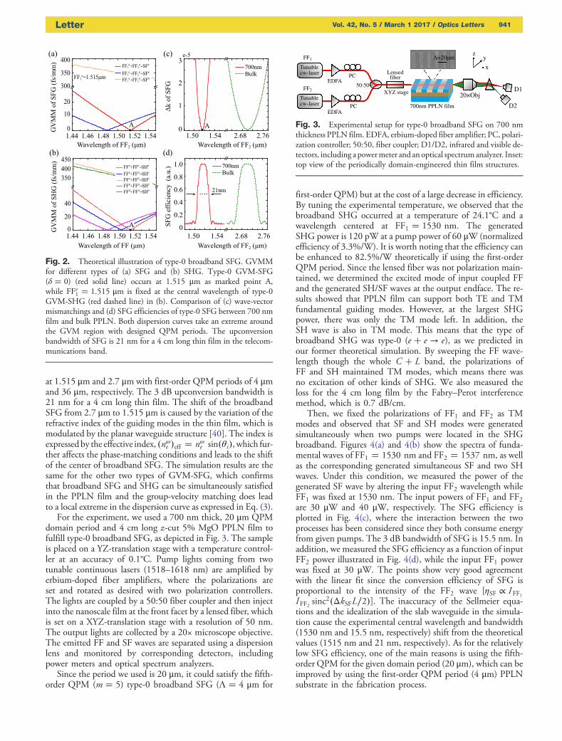
at 1.515 μm and 2.7 μm with first-order QPM periods of 4 μmand 36 μm, respectively. The 3 dB upconversion bandwidth is21 nm for a 4 cm long thin film. The shift of the broadbandSFG from 2.7 μm to 1.515 μm is caused by the variation of therefractive index of the guiding modes in the thin film, which ismodulated by the planar waveguide structure [40]. The index isexpressed by the effective index, �nωe �eff � nωe sin�θi�, which fur-ther affects the phase-matching conditions and leads to the shiftof the center of broadband SFG. The simulation results are thesame for the other two types of GVM-SFG, which confirmsthat broadband SFG and SHG can be simultaneously satisfiedin the PPLN film and the group-velocity matching does leadto a local extreme in the dispersion curve as expressed in Eq. (3).
For the experiment, we used a 700 nm thick, 20 μm QPMdomain period and 4 cm long z-cut 5% MgO PPLN film tofulfill type-0 broadband SFG, as depicted in Fig. 3. The sampleis placed on a YZ-translation stage with a temperature control-ler at an accuracy of 0.1°C. Pump lights coming from twotunable continuous lasers (1518–1618 nm) are amplified byerbium-doped fiber amplifiers, where the polarizations areset and rotated as desired with two polarization controllers.The lights are coupled by a 50:50 fiber coupler and then injectinto the nanoscale film at the front facet by a lensed fiber, whichis set on a XYZ-translation stage with a resolution of 50 nm.The output lights are collected by a 20× microscope objective.The emitted FF and SF waves are separated using a dispersionlens and monitored by corresponding detectors, includingpower meters and optical spectrum analyzers.
Since the period we used is 20 μm, it could satisfy the fifth-order QPM (m � 5) type-0 broadband SFG (Λ � 4 μm for
first-order QPM) but at the cost of a large decrease in efficiency.By tuning the experimental temperature, we observed that thebroadband SHG occurred at a temperature of 24.1°C and awavelength centered at FF1 � 1530 nm. The generatedSHG power is 120 pW at a pump power of 60 μW (normalizedefficiency of 3.3%/W). It is worth noting that the efficiency canbe enhanced to 82.5%/W theoretically if using the first-orderQPM period. Since the lensed fiber was not polarization main-tained, we determined the excited mode of input coupled FFand the generated SH/SF waves at the output endface. The re-sults showed that PPLN film can support both TE and TMfundamental guiding modes. However, at the largest SHGpower, there was only the TM mode left. In addition, theSH wave is also in TM mode. This means that the type ofbroadband SHG was type-0 (e � e → e), as we predicted inour former theoretical simulation. By sweeping the FF wave-length though the whole C � L band, the polarizations ofFF and SH maintained TM modes, which means there wasno excitation of other kinds of SHG. We also measured theloss for the 4 cm long film by the Fabry–Perot interferencemethod, which is 0.7 dB/cm.
Then, we fixed the polarizations of FF1 and FF2 as TMmodes and observed that SF and SH modes were generatedsimultaneously when two pumps were located in the SHGbroadband. Figures 4(a) and 4(b) show the spectra of funda-mental waves of FF1 � 1530 nm and FF2 � 1537 nm, as wellas the corresponding generated simultaneous SF and two SHwaves. Under this condition, we measured the power of thegenerated SF wave by altering the input FF2 wavelength whileFF1 was fixed at 1530 nm. The input powers of FF1 and FF2are 30 μW and 40 μW, respectively. The SFG efficiency isplotted in Fig. 4(c), where the interaction between the twoprocesses has been considered since they both consume energyfrom given pumps. The 3 dB bandwidth of SFG is 15.5 nm. Inaddition, we measured the SFG efficiency as a function of inputFF2 power illustrated in Fig. 4(d), while the input FF1 powerwas fixed at 30 μW. The points show very good agreementwith the linear fit since the conversion efficiency of SFG isproportional to the intensity of the FF2 wave [ηSF ∝ IFF1IFF2 sinc
2�ΔkSFL∕2�]. The inaccuracy of the Sellmeier equa-tions and the idealization of the slab waveguide in the simula-tion cause the experimental central wavelength and bandwidth(1530 nm and 15.5 nm, respectively) shift from the theoreticalvalues (1515 nm and 21 nm, respectively). As for the relativelylow SFG efficiency, one of the main reasons is using the fifth-order QPM for the given domain period (20 μm), which can beimproved by using the first-order QPM period (4 μm) PPLNsubstrate in the fabrication process.
Fig. 2. Theoretical illustration of type-0 broadband SFG. GVMMfor different types of (a) SFG and (b) SHG. Type-0 GVM-SFG(δ � 0) (red solid line) occurs at 1.515 μm as marked point A,while FFe1 � 1.515 μm is fixed at the central wavelength of type-0GVM-SHG (red dashed line) in (b). Comparison of (c) wave-vectormismatchings and (d) SFG efficiencies of type-0 SFG between 700 nmfilm and bulk PPLN. Both dispersion curves take an extreme aroundthe GVM region with designed QPM periods. The upconversionbandwidth of SFG is 21 nm for a 4 cm long thin film in the telecom-munications band.
EDFA50:50
Tunable cw-laser
EDFA
Tunable cw-laser
LensedfiberPC
PC D2
20×ObjXYZ stage
FF1
FF2 D1
700nm PPLN film
Λ=20µm
x
yz
Fig. 3. Experimental setup for type-0 broadband SFG on 700 nmthickness PPLN film. EDFA, erbium-doped fiber amplifier; PC, polari-zation controller; 50:50, fiber coupler; D1/D2, infrared and visible de-tectors, including a powermeter and an optical spectrum analyzer. Inset:top view of the periodically domain-engineered thin film structures.
Letter Vol. 42, No. 5 / March 1 2017 / Optics Letters 941

In conclusion, we demonstrated the first, to the best of ourknowledge, type-0 broadband SFG based on z-cut 5% MgOperiodically poled lithium niobate thin film. In theory, wepredicted that there existed three types of broadband SFG bysimultaneously satisfying the QPM and GVM conditions.We experimentally observed type-0 broadband SFG by usingthe highest nonlinear coefficient d 33 on a 700 nm thick and20 μm period sample. The measured upconversion bandwidthof SFG is 15.5 nm. The efficiency can be enhanced to 82.5%/Wtheoretically for the 4 cm long crystal if using the first-orderQPM period PPLN substrate (4 μm) in the fabrication processand the bandwidth can be broader by shorter interaction length.This could lead to the realization of more advanced and com-plicated photonic integration devices and circuits that basedon the broadband properties, for example, chip-scale all-opticalwavelength broadcast [41], broadband spectroscopy [42],quantum information processing [43], LN-thin-film-based mi-croresonator [44] and optical nonreciprocity devices [45], etc.
Funding. National Natural Science Foundation of China(NSFC) (11574208, 61235009).
REFERENCES
1. R. W. Boyd, Nonlinear Optics (Academic, 2003).2. K. Osvay and I. N. Ross, J. Opt. Soc. Am. B 13, 1431 (1996).3. A. G. Lambert, P. B. Davies, and D. J. Neivandt, Appl. Spectrosc. Rev.
40, 103 (2005).4. D. Verreault, V. Kurz, C. Howell, and P. Koelsch, Rev. Sci. Instrum.
81, 063111 (2010).5. S. Arahira, H. Murai, and H. Sasaki, Opt. Express 24, 19581 (2016).6. N. Gisin, G. Ribordy, W. Tittel, and H. Zbinden, Rev. Mod. Phys. 74,
145 (2002).7. R. B. Varillas, A. Candeo, D. Viola, M. Garavelli, S. De Silvestri, G.
Cerullo, and C. Manzoni, Opt. Lett. 39, 3849 (2014).
8. O. Kuzucu, F. N. Wong, S. Kurimura, and S. Tovstonog, Opt. Lett. 33,2257 (2008).
9. L. Foglia, M. Wolf, and J. Stähler, Appl. Phys. Lett. 109, 202106(2016).
10. A. J. Lee, H. M. Pask, and T. Omatsu, Appl. Phys. B 122, 1 (2016).11. J. S. Dam, P. Tidemand-Lichtenberg, and C. Pedersen, Nat.
Photonics 6, 788 (2012).12. Y. Lü, X. Zhang, X. Fu, J. Xia, T. Zheng, and J. Chen, Laser Phys. Lett.
7, 634 (2010).13. A. Weiner, IEEE J. Quantum Electron. 19, 1276 (1983).14. C. Rulliere, Femtosecond Laser Pulses (Springer, 2005).15. J. Armstrong, N. Bloembergen, J. Ducuing, and P. Pershan, Phys.
Rev. 127, 1918 (1962).16. H. S. Chan, Z. M. Hsieh, W. H. Liang, A. Kung, C. K. Lee, C. J. Lai,
R. P. Pan, and L. H. Peng, Science 331, 1165 (2011).17. M. Ahlawat, A. Bostani, A. Tehranchi, and R. Kashyap, Opt. Lett. 38,
2760 (2013).18. N. E. Yu, J. H. Ro, M. Cha, S. Kurimura, and T. Taira, Opt. Lett. 27,
1046 (2002).19. G. Z. Li, Y. P. Chen, H. W. Jiang, and X. F. Chen, Photon. Res. 3, 168
(2015).20. H. Leng, X. Yu, Y. Gong, P. Xu, Z. Xie, H. Jin, C. Zhang, and S. Zhu,
Nat. Commun. 2, 429 (2011).21. H. Jin, F. Liu, P. Xu, J. Xia, M. Zhong, Y. Yuan, J. Zhou, Y. Gong, W.
Wang, and S. Zhu, Phys. Rev. Lett. 113, 103601 (2014).22. T. W. Neely, L. Nugent-Glandorf, F. Adler, and S. A. Diddams, Opt.
Lett. 37, 4332 (2012).23. J. Sun and C. Xu, Opt. Lett. 37, 2028 (2012).24. M. M. Fejer, G. Magel, D. H. Jundt, and R. L. Byer, IEEE J. Quantum
Electron. 28, 2631 (1992).25. G. Poberaj, H. Hu, W. Sohler, and P. Guenter, Laser Photon. Rev. 6,
488 (2012).26. L. Cai, H. Han, S. Zhang, H. Hu, and K. Wang, Opt. Lett. 39, 2094
(2014).27. H. C. Huang, J. I. Dadap, G. Malladi, I. Kymissis, H. Bakhru, and R. M.
Osgood, Opt. Express 22, 19653 (2014).28. C. Wang, M. J. Burek, Z. Lin, H. A. Atikian, V. Venkataraman, I. C.
Huang, P. Stark, and M. Lončar, Opt. Express 22, 30924 (2014).29. J. Lin, Y. Xu, Z. Fang, M. Wang, J. Song, N. Wang, L. Qiao, W. Fang,
and Y. Cheng, Sci. Rep. 5, 8072 (2015).30. R. Geiss, S. Saravi, A. Sergeyev, S. Diziain, F. Setzpfandt, F.
Schrempel, R. Grange, E.-B. Kley, A. Tünnermann, and T. Pertsch,Opt. Lett. 40, 2715 (2015).
31. L. Chang, Y. Li, N. Volet, L. Wang, J. Peters, and J. E. Bowers, Optica3, 531 (2016).
32. A. Rao, M. Malinowski, A. Honardoost, J. R. Talukder, R. Rabiei, P.Delfyett, and S. Fathpour, “Second-harmonic generation inperiodically-poled thin film lithium niobate wafer-bonded on silicon,”arXiv:1609.09117 (2016).
33. S. Kim and V. Gopalan, Mater. Sci. Eng. B 120, 91 (2005).34. F. Van Laere, G. Roelkens, M. Ayre, J. Schrauwen, D. Taillaert, D.
Van Thourhout, T. F. Krauss, and R. Baets, J. Lightwave Technol.25, 151 (2007).
35. L. Golovan, G. Petrov, V. Y. Gayvoronsky, I. Pritula, and V. Yakovlev,Laser Phys. Lett. 11, 075901 (2014).
36. M. Gong, Y. Chen, F. Lu, and X. Chen, Opt. Lett. 35, 2672 (2010).37. J. Zhang, Y. Chen, F. Lu, and X. Chen, Opt. Lett. 16, 6957 (2008).38. W.Dang,Y.Chen,M.Gong,andX.Chen,Appl.Phys.B110, 477 (2013).39. O. Gayer, Z. Sacks, E. Galun, and A. Arie, Appl. Phys. B 91, 343
(2008).40. A. W. Snyder and J. Love, Optical Waveguide Theory (Springer,
2012).41. M. Ahlawat, A. Tehranchi, K. Pandiyan, M. Cha, and R. Kashyap, Opt.
Express 20, 27425 (2012).42. K. Huang, X. Gu, H. Pan, E. Wu, and H. Zeng, Appl. Phys. Lett. 100,
151102 (2012).43. S. Tanzilli, W. Tittel, M. Halder, O. Alibart, P. Baldi, N. Gisin, and H.
Zbinden, Nature 437, 116 (2005).44. W. C. Jiang and Q. Lin, Sci. Rep. 6, 36920 (2016).45. L. Chang, X. Jiang, S. Hua, C. Yang, J. Wen, L. Jiang, G. Li, G. Wang,
and M. Xiao, Nat. Photonics 8, 524 (2014).
Wavelength of SF (nm)
(b)
764760 772768
Spec
trum
of S
F (a
.u.)
0
0.2
0.4
0.6
0.8
SH2
SF
SH1
ExperimentLinear fit
(d)
Input Power of FF2 (µW)
0
10
(c)
Wavelength of FF2 (nm)15301520 15501540
Pow
er o
f SFG
(pW
)
0
32
40
16
Pow
er o
f SFG
(pW
)
1.0
8
24
(a)
Wavelength of FF (nm)1530.01529.6 1536.8 1537.2
Spec
trum
of F
F (µ
W)
0
1
2
3
FF1FF25
4
ΔλSFG=15.5nm
20
40
100 3020 40
30
Fig. 4. Observed type-0 broadband SFG. (a) Spectra of two funda-mental waves. (b) Spectra of the generated SF and two SH waves.(c) SFG power as a function of fundamental wave FF2, while FF1is fixed at 1530 nm. The SFG bandwidth is 15.5 nm for a 4 cm longcrystal. (d) Linear relationship between the SFG power and the inputFF2 power, while the input FF1 power is fixed at 30 μW.
942 Vol. 42, No. 5 / March 1 2017 / Optics Letters Letter