brittle archaeological silver :::: a fracture mechanisms
TRANSCRIPT

NLR-TP-2001-369
Brittle archaeological silverBrittle archaeological silverBrittle archaeological silverBrittle archaeological silver ::::a fracture mechanisms assessmenta fracture mechanisms assessmenta fracture mechanisms assessmenta fracture mechanisms assessment
R.J.H. Wanhill
CORE Metadata, citation and similar papers at core.ac.uk
Provided by NLR Reports Repository
Nationaal Lucht- en RuimtevaartlaboratoriumNational Aerospace Laboratory NLR
NLR-TP-2001-369
Brittle archaeological silver :a fracture mechanisms assessment
R.J.H. Wanhill
This report has been prepared as a contribution to the archaeometallurgical literature.
The contents of this report may be cited on condition that full credit is given to NLR andthe author.
Division: Structures and MaterialsIssued: 14 August 2001Classification of title: Unclassified
-2-NLR-TP-2001-369
Contents
1 Abstract and keywords 3
2 Introduction 3
3 Types of embrittlement 4- Corrosion-induced embrittlement 4- Microstructurally-induced embrittlement 4- Synergistic embrittlement 5
4 Grain boundary character 5
5 Embrittlement fracture mechanisms 6- Microcrack initiation 6- Microcracks to macrocracks: frangibility and friability 8
6 Conclusions 9
7 References 9
6 Figures
(16 pages in total)
-3-NLR-TP-2001-369
BRITTLE ARCHAEOLOGICAL SILVER : AFRACTURE MECHANISMS ASSESSMENT
R.J.H. WanhillNational Aerospace Laboratory NLR, Anthony Fokkerweg 2,
1059 CM Amsterdam, The Netherlands
ABSTRACT
Archaeological silver may be embrittled by long-term corrosion and microstructural changes.The embrittlement increases with increasing grain size, and the combination of a large grain sizewith synergistic embrittlement (conjoint action of corrosion-induced and microstructurally-induced embrittlement) is particularly detrimental. Micromechanical models of cracking thatincorporate the grain size provide insight into the severity of embrittlement. Severely embrittledartifacts are frangible or even friable.
KEYWORDS: ARCHAEOLOGICAL SILVER, EMBRITTLEMENT, GRAIN SIZE,CRACKS, FRACTURE.
INTRODUCTION
Archaeological silver may be brittle owing to long-term corrosion and microstructural changes(Thompson and Chatterjee 1954; Werner 1965; Ravich 1993; Wanhill et al. 1998; Wanhill2000, 2001a). Corrosion-induced embrittlement and microstructurally-induced embrittlementmay be independent of each other but can also act synergistically (Wanhill et al. 1998; Wanhill2000, 2001a).
Metallographic observations have shown that the grain size is an important factor forarchaeological silver embrittlement. Large-grained artifacts appeared to be more susceptible tocracking (Werner 1965). Also, the combination of a large grain size with synergisticembrittlement is particularly detrimental (Wanhill et al. 1998).
The present work assesses these observations using micromechanical models of cracking. To dothis it is necessary first to describe the types of embrittlement and the concept of grain boundarycharacter. However, the physical and chemical mechanisms of embrittlement are discussed

-4-NLR-TP-2001-369
elsewhere, as are the diagnostic techniques and remedial measures (Wanhill et al. 1998; Wanhill2000, 2001a).
TYPES OF EMBRITTLEMENT
Corrosion-induced embrittlement
Archaeological silver undergoes general corrosion, which results in a brittle, finely granularsurface layer of silver chloride (Gowland 1918; Scott 1996; Wanhill 2000, 2001a). This surfacecorrosion does not affect the remaining metal�s integrity, although unfavourable conditions mayresult in an artifact being completely converted to silver chloride (Gowland 1918).
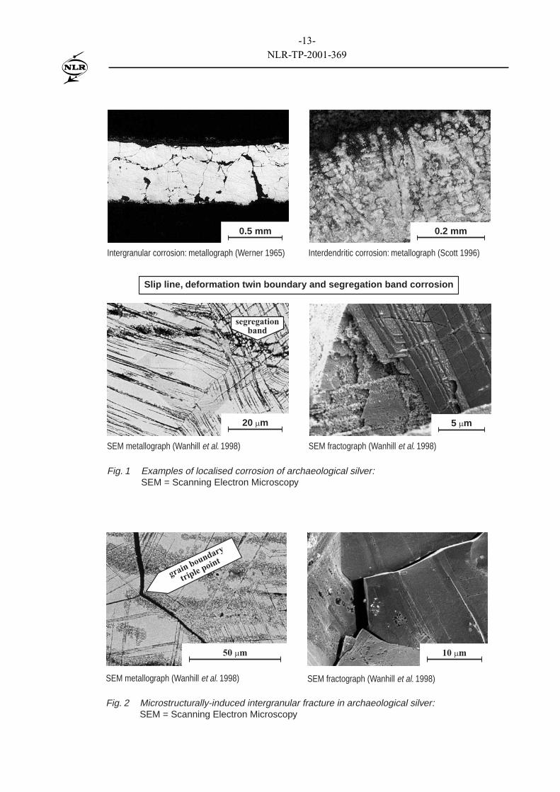
Even so, some artifacts experience localised corrosion that penetrates the silver and enablesembrittlement due to cracking along the corrosion paths (Werner 1965; Ravich 1993; Wanhillet al. 1998). Examples are shown in figure 1. Intergranular corrosion can occur in mechanicallyworked and annealed artifacts. Interdendritic corrosion can occur in castings with essentiallyas-cast microstructures, i.e. little changed by any subsequent mechanical working or annealing,see Scott (1996). Corrosion along slip lines and deformation twin boundaries can occur in anartifact that has not been annealed after final mechanical working, which includes chased andstamped decorations (Wanhill et al. 1998): inside the silver these forms of corrosion can lead toadditional corrosion along segregation bands. These bands are the remains, modified bymechanical working and annealing heat-treatments, of solute element segregation (coring) andinterdendritic segregation that occurred during solidification of an ingot or cupelled button.
Cracking along the corrosion paths in the silver usually results in irregular fracture surfaces witha finely granular appearance. However, highly localised corrosion along slip lines anddeformation twin boundaries results in crystallographic fractures, for example the fractograph infigure 1.
Microstructurally-induced embrittlement
This type of embrittlement is most probably a consequence of long-term low temperatureageing, whereby segregation of an impurity element, or elements, occurs to grain boundaries(Wanhill et al. 1998; Wanhill 2000, 2001a). Cracking appears to be entirely intergranular, andexamples are shown in figure 2. The cracks are characteristically narrow and sharp (unlikeintergranular corrosion, see figure 1) except where grains can become bodily displaced, which isitself a characteristic of severe embrittlement. One such displacement is shown in the SEMfractograph of figure 2.

-5-NLR-TP-2001-369
The grain boundary fracture facets are initially clean. Long-term environmental exposure cancause the facets to become locally corroded where slip lines, deformation twin boundaries andsegregation bands intersect the fracture surfaces.
Synergistic embrittlement
As stated in the introduction, corrosion-induced and microstructurally-induced embrittlementcan act synergistically (Wanhill et al. 1998; Wanhill 2000, 2001a). Figure 3 gives examples ofthe appearances of synergistic embrittlement. Corrosion along slip lines, deformation twinboundaries and segregation bands can result in cracks under the action of external loads orforces (e.g. crushing pressures during interment) and internal residual stresses due to retainedcold-work. These cracks can then initiate fracture along microstructurally embrittled grainboundaries � which may fracture anyway, though less easily � under the action of external loadsor forces. In turn, grain boundary fractures expose more slip lines, deformation twins andsegregation bands to the environment and therefore increase the opportunities for corrosion.
GRAIN BOUNDARY CHARACTER
Grain boundaries strongly influence the properties of metals and alloys. This was firstrecognised in the derivation of �laws� describing property-dependence on a length scale, usuallythe average grain size or diameter, d. Examples are the Herring-Nabarro relationship for thestrain rate in creep controlled by lattice diffusion of vacancies, 2d−∝ε# ; the Coble relationship
for the strain rate in creep controlled by grain boundary diffusion of vacancies, 3d−∝ε# ; and the
Hall-Petch relationships for plastic yield stress, σy ∝ d-1/2, or fracture stress, σf ∝ d-1/2 (Herring1950; Nabarro 1948; Coble 1963; Hall 1951; Petch 1953).
These length scale criteria assume all grain boundaries are similar. However, there is now muchevidence that grain boundaries have different properties depending on their character, i.e. theirtype and structure (Chadwick and Smith 1976; Baluffi 1980; Watanabe 1984, 1993, 1994;Watanabe et al. 1980, 1989; Lim and Watanabe 1990).
From the literature and their own research Watanabe (1984, 1993, 1994) and Watanabe et al.(1980, 1989) suggested dividing grain boundaries into three character- and property-determinedcategories: low-angle boundaries with misorientation angles less than 15°, high-angle

-6-NLR-TP-2001-369
coincidence boundaries with low Σ* coincidence, and high-angle random boundaries. The basicdistinguishing feature is that low-angle and low Σ coincidence boundaries are low-energyboundaries, while random boundaries are high-energy boundaries.
This distinction between grain boundary types and structures is relevant to microstructurally-induced embrittlement of archaeological silver, for two reasons:
(1) Most silver artifacts were made using combinations of mechanical working and annealingheat-treatments. The resulting microstructures will have mainly high-angle random grainboundaries, see by analogy Watanabe (1984) and Watanabe et al. (1989). This means theartifacts will contain many grain boundaries susceptible to microstructurally-inducedembrittlement, assuming that impurity element segregation has occurred (Wanhill 2001a).
(2) A preponderance of high-angle random grain boundaries makes it reasonable, and indeedcompatible with empirical observations (Werner 1965), to consider embrittlement interms of length scale criteria based on the average grain size or diameter, d.
EMBRITTLEMENT FRACTURE MECHANISMS
Microcrack initiation
Embrittlement is manifested by cracking under the action of external loads or forces and internalresidual stresses, if present. Cracking begins with microcracks smaller than or equal to the grainsize. At this size or length scale the average grain size or diameter, d , symbolising apreponderance of high-angle random grain boundaries, is likely to strongly influence crackinitiation.
Figure 4 depicts microcrack models applicable to archaeological silver embrittlement. A fulldiscussion of these models, in mainly non-mathematical detail, is given in Wanhill (2001b). Thefollowing sub-paragraphs summarise the models.
• Figure 4a: This is the classic dislocation pile-up model of microcrack initiation, applicable tocorrosion-induced and microstructurally-induced embrittlement, whereby corrosion or
* A coincidence boundary is a lattice plane in both contiguous grains. A boundary with low Σ coincidence
means the contiguous grains have orientations resulting in a high density of coincident lattice sites onthe boundary.

-7-NLR-TP-2001-369
impurity element segregation reduce the grain boundary fracture energy. The criterion forinitiation of a grain boundary microcrack is obtained from Smith and Barnby (1967):
)(F1
d)1(2 f
iappθ
•ν−
πµγ≥τ−τ (1)
where τapp = applied shear stress; τi = lattice friction stress; µ = shear modulus; γf = grainboundary fracture energy; ν = Poisson�s ratio; d = grain diameter; F(θ) = an angularfunction; S = dislocation source; ⊥⊥⊥⊥ , ȸ = edge dislocations of opposite sign.
• Figures 4b-4d: These models are applicable to corrosion-induced and synergisticembrittlement, whereby microcracks develop due to corrosion along slip planes and facilitateinitiation of microcracks at grain boundaries weakened by corrosion or impurity elementsegregation. The criteria for initiation of grain boundary microcracks are:
)(F1
2/dacos
21
1d)1(
2
1
app
i
fapp
θ•
•
πττ
−
•ν−
πµγ≥τ
−
(2)
)(F1
d)1(2 f
appθ
•ν−
πµγ≥τ (3)
)(F1
2865.0hd
dh3
1d)1(
2 fapp
θ•
+•
π
•ν−
πµγ≥τ (4)
where h is the distance between multiple slip plane cracks (see, for example, figure 3).Equations (2) - (4) are derived from equation (1) and the analyses of Tanaka et al. (1986) forequation (2) and Tada et al. (1973) for equation (4). N.B. For mathematical simplicity thesemodels assume the material to be elastically isotropic and homogeneous. On the scale ofindividual grains this is incorrect for most metals, including silver (Smithells 1967), but thisdoes not invalidate a generic assessment.
The models make the general prediction that the applied shear stress, τapp, required for initiationof a grain boundary microcrack decreases with increasing grain size, d, and decreasing grain
Fig. 4b2a < d
Fig. 4c2a = d
Fig. 4b2a = d
multipleslip plane
cracks
-8-NLR-TP-2001-369
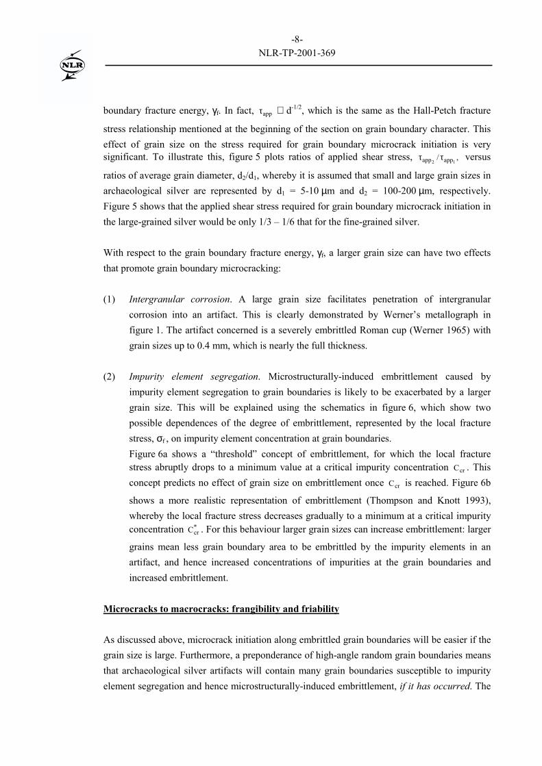
boundary fracture energy, γf. In fact, appτ ∝ d-1/2, which is the same as the Hall-Petch fracture
stress relationship mentioned at the beginning of the section on grain boundary character. Thiseffect of grain size on the stress required for grain boundary microcrack initiation is verysignificant. To illustrate this, figure 5 plots ratios of applied shear stress, ,/
12 appapp ττ versus
ratios of average grain diameter, d2/d1, whereby it is assumed that small and large grain sizes inarchaeological silver are represented by d1 = 5-10 µm and d2 = 100-200 µm, respectively.Figure 5 shows that the applied shear stress required for grain boundary microcrack initiation inthe large-grained silver would be only 1/3 � 1/6 that for the fine-grained silver.
With respect to the grain boundary fracture energy, γf, a larger grain size can have two effectsthat promote grain boundary microcracking:
(1) Intergranular corrosion. A large grain size facilitates penetration of intergranularcorrosion into an artifact. This is clearly demonstrated by Werner�s metallograph infigure 1. The artifact concerned is a severely embrittled Roman cup (Werner 1965) withgrain sizes up to 0.4 mm, which is nearly the full thickness.
(2) Impurity element segregation. Microstructurally-induced embrittlement caused byimpurity element segregation to grain boundaries is likely to be exacerbated by a largergrain size. This will be explained using the schematics in figure 6, which show twopossible dependences of the degree of embrittlement, represented by the local fracturestress, σf , on impurity element concentration at grain boundaries.Figure 6a shows a �threshold� concept of embrittlement, for which the local fracturestress abruptly drops to a minimum value at a critical impurity concentration crC . Thisconcept predicts no effect of grain size on embrittlement once crC is reached. Figure 6b
shows a more realistic representation of embrittlement (Thompson and Knott 1993),whereby the local fracture stress decreases gradually to a minimum at a critical impurityconcentration *
crC . For this behaviour larger grain sizes can increase embrittlement: larger
grains mean less grain boundary area to be embrittled by the impurity elements in anartifact, and hence increased concentrations of impurities at the grain boundaries andincreased embrittlement.
Microcracks to macrocracks: frangibility and friability
As discussed above, microcrack initiation along embrittled grain boundaries will be easier if thegrain size is large. Furthermore, a preponderance of high-angle random grain boundaries meansthat archaeological silver artifacts will contain many grain boundaries susceptible to impurityelement segregation and hence microstructurally-induced embrittlement, if it has occurred. The

-9-NLR-TP-2001-369
combination of large grain size and a preponderance of high-angle random grain boundaries in amicrostructurally embrittled artifact means many potential initiation sites for microcracks, andhence an increased possibility for microcracks to link up and become macrocracks. In otherwords, a large-grained microstructurally embrittled artifact is likely to be frangible, even if thereis no damage from corrosion.
A severely corroded large-grained artifact will be frangible (Werner 1965). And thecombination of a large grain size with synergistic embrittlement is even worse: corrosionincreases the possibilities for microcrack initiation at microstructurally embrittled grainboundaries, as discussed with reference to figures 3 and 4, and the artifact can become friable(Wanhill et al. 1998).
CONCLUSIONS
(1) Embrittlement of archaeological silver may be considered in terms of length scale criteriabased on the average grain size or diameter. Micromechanical models of cracking thatincorporate the grain size provide insight into the severity of embrittlement.
(2) Larger grains increase embrittlement in several ways:• by facilitating penetration of intergranular corrosion• by enabling increased grain boundary concentrations of impurities causing
microstructurally-induced embrittlement• by facilitating grain boundary microcrack initiation, which may be involved in
corrosion-induced, microstructurally-induced and synergistic embrittlement• by providing many potential initiation sites for microcracks and hence an increased
possibility for microcracks to become macrocracks.
(3) Severely embrittled artifacts are frangible or even friable.
REFERENCES
Baluffi, R.W. (ed.), 1980, Grain Boundary Structure and Kinetics, American Society for Metals(ASM), Metals Park, Ohio, U.S.A.
Chadwick, G.A., and Smith, D.A. (eds.), 1976, Grain Boundary Structure and Properties,Academic Press, London, U.K.

-10-NLR-TP-2001-369
Coble, R.L., 1963, A model for boundary diffusion controlled creep in polycrystalline materials,Journal of Applied Physics, 34, 1679-1682.
Gowland, W., 1918, Silver in Roman and earlier times: I. Pre-historic and proto-historic times,Archaeologia, 69, 121-160.
Hall, E.O., 1951, The deformation and ageing of mild steel: III discussion of results,Proceedings of the Physical Society of London, B64, 747-753.
Herring, C., 1950, Diffusional viscosity of a polycrystalline solid, Journal of Applied Physics,21, 437-445.
Lim, L.C., and Watanabe, T., 1990, Fracture toughness and brittle-ductile transition controlledby grain boundary character distribution (GBCD) in polycrystals, Acta Metallurgica etMaterialia, 38, 2507-2516.
Nabarro, F.R.N., 1948, Deformation of crystals by the motion of single ions, Report of aConference on the Strength of Solids, 75-90, The Physical Society, London, U.K.
Petch, N.J., 1953, The cleavage strength of polycrystals, Journal of the Iron and Steel Institute,174, 25-28.
Ravich, I.G., 1993, Annealing of brittle archaeological silver: microstructural and technologicalstudy, in 10th Triennial Meeting of the International Council of Museums Committee forConservation, Preprints of the Seminar: August 22/27, 1993, II, 792-795, Washington, D.C.,U.S.A.
Scott, D.A., 1996, Technical study of a ceremonial Sican tumi figurine, Archaeometry, 38,305-311.
Smith, E., and Barnby, J.T., 1967, Crack nucleation in crystalline solids, Metal Science Journal,1, 56-64.
Smithells, C.J., 1967, Metals Reference Book, Volume 3, Fourth Edition, 708, 709,Butterworths, London, U.K.
Tada, H., Paris, P.C., and Irwin, G.R., 1973, The Stress Analysis of Cracks Handbook, 14.5, DelResearch Corporation, St. Louis, Missouri, U.S.A.

-11-NLR-TP-2001-369
Tanaka, K., Akiniwa, Y., Nakai, Y., and Wei, R.P., 1986, Modelling of small fatigue crackgrowth interacting with grain boundary, Engineering Fracture Mechanics, 24, 803-819.
Thompson, A.W., and Knott, J.F., 1993, Micromechanisms of brittle fracture, MetallurgicalTransactions A, 24A, 523-534.
Thompson, F.C., and Chatterjee, A.K., 1954, The age-embrittlement of silver coins, Studies inConservation, 1, 115-126.
Wanhill, R.J.H., Steijaert, J.P.H.M., Leenheer, R., and Koens, J.F.W., 1998, Damageassessment and preservation of an Egyptian silver vase (300-200 BC), Archaeometry, 40,123-137: also NLR Technical Publication NLR TP 95372 L, National Aerospace LaboratoryNLR, Amsterdam, The Netherlands.
Wanhill, R.J.H., 2000, Brittle archaeological silver. Identification, restoration and conservation,Materialen, 16, 30-35: also NLR Technical Publication NLR TP 97647 L, National AerospaceLaboratory NLR, Amsterdam, The Netherlands.
Wanhill, R.J.H., 2001a, Microstructurally-induced embrittlement of archaeological silver, NLRTechnical Publication NLR-TP-2001-032, National Aerospace Laboratory NLR, Amsterdam,The Netherlands.
Wanhill, R.J.H., 2001b, The role of grain size in embrittlement of archaeological silver, NLRTechnical Publication NLR-TP-2001-125, National Aerospace Laboratory NLR, Amsterdam,The Netherlands.
Watanabe, T., Kitamura, S., and Karashima, S., 1980, Grain boundary hardening andsegregation in alpha iron-tin alloy, Acta Metallurgica, 28, 455-463.
Watanabe, T., 1984, An approach to grain boundary design of strong and ductile polycrystals,Res Mechanica, 11, 47-84.
Watanabe, T., Fujii, H., Oikawa, H., and Arai, K.I., 1989, Grain boundaries in rapidly solidifiedand annealed Fe-6.5 mass % Si polycrystalline ribbons with high ductility, Acta Metallurgica,37, 941-952.
Watanabe, T., 1993, Grain boundary design and control for high temperature materials,Materials Science and Engineering, A166, 11-28.

-12-NLR-TP-2001-369
Watanabe, T., 1994, The impact of grain boundary character distribution on fracture inpolycrystals, Materials Science and Engineering, A176, 39-49.
Werner, A.E., 1965, Two problems in the conservation of antiquities: corroded lead and brittlesilver, in Application of Science in Examination of Works of Art (Editor W.J. Young), 96-104,Boston Museum of Fine Arts, Boston, Massachusetts, U.S.A.
�������������� ��
Fig. 1 Examples of localised corrosion of archaeological silver:SEM = Scanning Electron Microscopy
SEM metallograph (Wanhill et al. 1998) SEM fractograph (Wanhill et al. 1998)
Slip line, deformation twin boundary and segregation band corrosion
20 �m 5 �m
Intergranular corrosion: metallograph (Werner 1965) Interdendritic corrosion: metallograph (Scott 1996)
segregationband
segregationband
0.5 mm 0.2 mm
SEM metallograph (Wanhill et al. 1998) SEM fractograph (Wanhill et al. 1998)
50 �m
grain boundary
triple point
10 �m
Fig. 2 Microstructurally-induced intergranular fracture in archaeological silver:SEM = Scanning Electron Microscopy
-13-NLR-TP-2001-369

�������������� ��
Fig. 3 Examples of synergistic embrittlement owing to microstructurally-inducedembrittlement (intergranular fracture) and corrosion-induced embrittlement alongslip lines, deformation twin boundaries and segregation bands: SEM = ScanningElectron Microscopy
Corrosion along slip lines intersecting grain boundaryfacets: SEM fractograph (Wanhill et al. 1998)
Corrosion along deformation twin boundariesintersecting a grain boundary facet: SEM fractograph(Wanhill et al. 1998)
20 �m 10 �m
annealingtwin
Corrosion along segregation bands intersecting grain boundary facets: SEM fractograph (Wanhill et al. 1998)
20 �m
-14-NLR-TP-2001-369

�������������� ��
a
d/2
slip plane
�
�app–�i
�f
d/2
�app–�iS
b
d
2a
slip plane
��f
�app
�app
2a = d
slip plane
��f
�app
�app
2a � d
�app
�app
slip planes h
�f
�
c d
Fig. 4 Models of microcrack initiation at grain boundaries in embrittled archaeological silver.�app = applied shear stress; �i = lattice friction stress; �f = grain boundary fracture energy;2a = slip plane crack length; d = grain diameter; h = distance between parallel slip planecracks; S = dislocation source; , = edge dislocations of opposite sign
-15-NLR-TP-2001-369

�������������� ��
Fig. 5 Dimensionless plot of the applied shear stress, �app, versus average grain diameter, d,using the proportionality �app � 1/d
Fig. 6 Dependence of local fracture stress, �f , on impurity element concentration at grainboundaries: (a) “threshold” model behaviour in which fracture stress is abruptly lowered ata critical impurity element concentration, Ccr; (b) more realistic behaviour with fracturestress gradually decreasing to a minimum at a critical impurity element concentration, C*cr.After Thompson and Knott (1993)
�app2/�app1
0.1
1
2
�app2/�app1
= 0.316
�app2/�app1
= 0.158
d1 = 5–10 �m (fine grain size)d2 = 100–200 �m (large grain size)
1 10 102
d2/d1
Localfracturestress, �f
Ccr C*cr
(a) (b)
Impurity element concentration at grain boundaries
-16-NLR-TP-2001-369