bridges built with advanced materials
TRANSCRIPT
338-1
9th International Conference on Short and Medium Span Bridges
Calgary Alberta Canada July 15-18 2014
Bridges Built with Advanced Materials
Juan A Sobrino PhD PEng PE
Director PEDELTA Toronto ON Canada
Javier Jordan MSc PE
Technical Director PEDELTA Toronto ON Canada
Dritan Topuzi MEng PMP
Principal PEDELTA Toronto ON Canada
ABSTRACT
In spite of the impact that composite materials and Stainless Steel have had in the aircraft and naval construction
industries architecture or multitude of consumer products for more than 50 years their presence in civil engineering
structures is recent In the last two decades some interesting structures mainly pedestrian bridges have been built
Advanced materials such as Stainless Steel and GFRP (Glass Fiber Reinforced Polymers) make possible to build
light durable safe and elegant structures The higher construction cost is offset during the life of the structure
thanks to the minimum maintenance required for these materials This paper provides an overview of the design
criteria performance unique properties and applications of these advanced materials in bridges through several case
studies designed by the authors and built in Spain in the past decade
1 ADVANCED MATERIALS FOR BRIDGES
There is a need of advanced structural materials for applications in aggressive environments or for reducing weight
The use of advanced materials allows to building light durable and attractive bridges Stainless steel (typically
Duplex Grades) and GFRP (Glass Fibre Reinforced Polymers) are high durable materials that provide outstanding
mechanical properties and magnificent aesthetical possibilities (Baddoo et al 2012) (Keller 2003) The larger
construction cost can be offset during the long life of the structure thanks to substantial savings in the cost of
maintenance and replacement of bridge components
The full potential of these two materials is reached in locations with aggressive environment (for instance in marine
environments or where de-icing salts are used) and their application is steadily increasing
11 Duplex Stainless Steel
Though the variety of the stainless steels is enormous it is possible to find more than 100 types of frequently used
grades they contain as a common denominator the presence of at least 11 of chromium that with the presence of
other components as nickel molybdenum or nitrogen among others gives a steel alloy that exhibits a great
corrosion resistance ductility and mechanical strength even when exposed to high temperatures as well as
excellent aesthetic possibilities and easy maintenance and cleaning The chromium contained in the stainless steel
forms a soft stable and transparent layer of chromium oxide (Cr2O3) on the surface (passivation layer) that avoids
corrosion
Four types of stainless steel exist according to their metallurgical structure ferritic austenitic duplex and
martensitic Duplex stainless steel is an austenitic-ferritic alloy with a microstructure of great corrosion resistance
excellent ductility and mechanical characteristics superior to the great majority of carbon steels Thanks to their high
338-2
strength duplex steels are suitable for application in bridges and pedestrian bridges (Baddoo 2013) (Helzel 2004)
With the existence of a wide range of duplex steel grades the selection of the most suitable type clearly depends on
the ambient aggressiveness type of corrosion mechanical properties types of surface finish and so forth
Stainless steel unlike the conventional carbon steels presents a mechanical nonlinear behaviour even under
reduced stress values without having an elastic limit strength clearly defined However the stress value associated
to a strain of 02 has been adopted as a conventional yield stress f02 (Baddoo 2013) Processes of construction
with stainless steel are similar to those used for carbon steels but not identical adopting specific techniques for
cutting bending forming welding and finishing Welding consumables must also be specific to the stainless steel
grade to guarantee equal mechanical and corrosion properties to those of the base material
12 Glass Fiber Reinforced Polymers (GFRP)
FRP materials are frequently used in aerospace marine automobile and leisure industries when high mechanical
strength light weight and corrosion resistance are needed Glass Fiber Reinforced Polymers are composite materials
made of Glass fibers (long or short fibers) on a polymeric matrix (usually isophthalic polyester vinylester epoxi or
phenol) Typically the matrix has low strength and modulus of elasticity with high ductility and fibers (the
reinforcement) provide high mechanical properties to the composite material although they exhibit a brittle
behaviour The arrangement of the fibers may be random or with a preferred orientation The mechanical and
chemical properties of the material depend on the properties arrangement and proportions of the constituents and
are strongly influenced by the fabrication process (Keller 2003) (ASCE 2011)
The use of fibre-reinforced plastic profiles in civil engineering structures has undergone a significant development
during the 90rsquos From the construction of the cable-stayed footbridge at Aberfeldy - UK 1992- to that of the
Pontresina footbridge -Switzerland 1997- several hundred further bridges have been built in the past twenty years
(mostly pedestrian bridges) Most of these recent structures are truss-type bridges using GFRP pultruded profiles
Pultrusion is a fabrication process to produce composite profiles with constant cross-sections and mechanical
properties Typically GFRP pultruded profiles have modulus of elasticity ranging from 23 to 28 GPa and flexural
strength around 240 MPa in the longitudinal direction The density of the GFRP is usually 18 (ASCE 2011)
GFRP exhibits excellent mechanical properties and light weight but due to its relatively low modulus of elasticity
GFRP structures are flexible and sensitive to dynamic effects Combination of GFRP and steel provides stiff
structures and still a reduced weight as has been proven in recent structures included in this article
2 CASE STUDIES
21 Minorca stainless steel vehicular bridge
This is the worldrsquos first duplex stainless steel vehicular bridge The bridge built in 2005 crosses the Algendar River
in Cala Galdana (Minorca Spain) and replaced an existing reinforced concrete bridge that experienced a significant
deterioration after 30 years of exposure to a marine environment After 9 years of service the new bridge is in
excellent conditions and has not undergone any corrosion
During the design process different structural and material alternatives were analysed Finally a duplex stainless
steel arch structure was chosen due to its high resistance to corrosion from the marine atmosphere as the solution
that better responded to the ownerrsquos requirements The new bridge has become a landmark for the island thanks to
the technological innovation of using stainless steel
The overall length of the bridge is 55 m with a 13 m wide deck The deck allocates 2 lanes of road traffic (7 m) and
two lateral sidewalks each 2 m wide that allow the pedestrians to enjoy the panoramic views from an excellent
location (Figure 1) The main structure consists of two parallel arches with an intermediate deck The arches and the
deck join at the abutments by means of an inclined strut that takes the horizontal component of the arch axial force
and consequently significant horizontal forces are not transferred to the abutments
338-3
Figure 1 Minorca Duplex Stainless Steel Bridge
The structural scheme is constituted by two parallel arches with a free span of 45 m and an intermediate deck The
main structure is made of duplex stainless steel grade 14462 which exhibits a high resistance to corrosion by
chlorides The deck is made of reinforced concrete connected to a series of transverse beams The arches rise to a
total of 6 m (relation spanrise = 75) and they are tied to the deck by means of two connected longitudinal beams
These longitudinal beams are again connected by means of transverse beams The arches have a triangular cross-
section with a central web Their depth is 070 m - constant throughout their overall length However the width of
the section varies between 07 and 1 m The central web of the section is transformed into a cellular plate that allows
connecting the arch with the longitudinal deck beam The longitudinal beams are rectangular hollow sections of 1 m
x 05 m constituted by plates with varying thicknesses between 15 and 25 mm In the central zone with the arch
above the deck these beams have a central web that is connected to the web of the arch allowing direct transfer of
the vertical loads of the longitudinal beam to the arch The transverse beams spaced at 2m are formed by
rectangular cross-sections 025 m wide and with a variable depth varying between 050 and 057 m (to obtain) the
deck cross-slope of 2) constituted by plates of 10 and 12 mm These beams are structurally connected to the
reinforced concrete slab having an average thickness of 030 m by means of Bernold type studs of 20 mm in
diameter
In order not to transmit the horizontal component of the arch axial force to the abutments two inclined struts ndash
connecting the base of the arch and the end of the longitudinal beam have been designed which are anchored at the
top of the abutments The struts have a rectangular hollow cross-section with outer dimensions of 1 m x 05 m
formed by plates of 20 and 25 mm thickness internally stiffened in both longitudinal and transverse directions
The lateral sidewalks are separated from the road by the arches These sidewalks are supported by means of a
reinforced concrete slab supported on transverse cantilever ribs every 2 m connected to the longitudinal beam
22 Sant Fruitoacutes Pedestrian bridge
Sant Fruitoacutes is a small town with more than ten centuries of history Located 59km from Barcelona close to
Manresa it occupies a strategic position for road communications in Catalonia The 20th century economic boost
and population growth have led to the creation of new residential areas around the historic core and consequently of
new public infrastructures The neighbourhood of Rosaleda a new residential area of Sant Fruitoacutes which hosts more
than 6 of its population is separated from a commercial district and the rest of the town by the N-141C a national
road The crossing of this road has caused many accidents some of them with casualties on the last few years The
Municipality decided to eliminate this risk by building a pedestrian bridge Additionally to its main function the
structure should be a new landmark and a gateway to the town representing its dynamic and innovative nature
338-4
The location of the bridge was fixed by the owner to provide a direct access to a bus stop The bridge built in 2009
crosses the N-141C road with a vertical clearance of 55m connecting areas with almost a difference of 6m in
elevation (Figure 2)
Figure 2 Sant Fruitos pedestrian bridge
The use of a bow-string reinterpretation - a classical structure as main element - and the stainless steel and GFRP
(glass fibre reinforced polymer) ndash high-performance and structurally innovative materials ndash are the key concepts
The leaned arch creates a dynamic and tense feeling and joins the deck for greater structural efficiency The
structure is sober very transparent and simple yet very expressive thanks to the use of extremely slender elements
and the arch geometry The crossing is now accessible to disabled people and bicycles by the slender concrete stairs
and panoramic lift on the residential side and the embankment stairsramps and stairs on the other
The structure with an overall length of 55 m is a tied arch with an intermediate deck The main components are
made of duplex stainless-steel The 40m span arch has a triangular section almost equilateral only 045m high and
it is tilted in plan and elevation forming an angle of 30 degrees with the vertical plan The arch cross-section is
fabricated with 20mm steel plates The 3m wide deck consists of a longitudinal trapezoidal box girder with ribs The
box cross-section is made of 10mm thickness plates Its shape is almost triangular 160m wide with constant depth
of 06 m The webs are 015 and 060m in height The 140m long ribs have a variable depth between 009 and
015m The deck is connected to the arch at one of the ends (elevator side) and in one intermediate section (36 m
from the elevator side) Stainless steel bars hangers 28mm in diameter spaced every 3m connect the deck and the
arch
The arch is supported in the elevator structure and on the other side rest over a small pier To not transmit any
horizontal force to the pierrsquos foundation an inclined strut element connects the end of the arch 5 m below the deck
level to the deck creating a V shape below the deck The light arch and the deck connected through hangers define
one of the most characteristic features of the structure a very attractive visual lightness and slenderness
The 14162 duplex stainless steel used in this footbridge contains less nickel than other duplex stainless types
Therefore its price is less variable and much lower than other duplex steels It is suitable for environments with an
average level of aggressiveness and it has a conventional yield strength of 480 MPa (more than 35 those of S355
carbon steel)
The deck consists of GFRP panels 05m wide 40mm in depth simply supported on the ribs or on the box girder To
avoid sliding these panels have a quartz sand surface coating
338-5
The dynamic test was conducted with people walking running or jumping (1 to 9 people) including eccentric load
cases 21 different load cases were defined covering a wide range of probable situations The response of the bridge
to dynamic load met the regulations and was very similar to the results of the dynamic calculation Measured
critical damping ratio is 00127
23 Lleida Pedestrian bridge over the High Speed Rail
This pedestrian bridge shown in Figure 3 is located 3 km from the city of Lleida (Spain) and was built in 2001 to
cross an already existing roadway a railway line and the new projected high-speed rail-way line between Madrid
and Barcelona The owners required a new pedestrian structure with minimum maintenance and which would be
easy to erect At the time of construction it was the first arch made of GFRP and the longest span made of standard
GFRP pultruded profiles After 12 years of service the bridge is in excellent condition and has not required any
maintenance
The most significant issue was that of finding an appropriate structural form to span the required 38 m of length
using standard GFRP profiles The final structure is a double-tied arch of 38 m span-length having a rise of 62 m
(spanrise 6) and 3 m wide The total weight of the bridge is approximately 19 Tons (Figure 3)
Figure 3 Lleida GFRP pedestrian bridge
All the profiles are made of fibre-reinforced plastics using continuous E-glass fibres combined with woven and
complex mats having a minimum glass-fibre content of 50 The matrix is made of isophthalic polyester The
modulus of elasticity in the longitudinal direction ranges from 23-27 GPa depending on the type of profile Its
tensile or compressive strength in the longitudinal direction is 240 MPa and its strength in the transverse direction
varies from 50-70 MPa
The arch configuration was chosen so as to minimize serviceability problems due to the low modulus of elasticity of
GFRP profiles The arches have been inclined by 6 to achieve a more expressive appearance Both arches and the
tied longitudinal members present a rectangular hollow cross-section made up of two U 300x90x15mm profiles
joined with glued flat plates of 180x12 mm so as to form a hollow rectangular tube The supplier of the profiles
carried out full-scale testing to verify the beam joints using the proposed epoxy adhesive In order to reduce
horizontal deformation of the arches due to wind pressure these elements are forked out into two branches using the
same profiled sections
The hangers are I-profiles of 160 x 80 x 8 The arches are connected by square tubes of 100 mm size and having
various thicknesses (6-8 mm) The deck is made up of transverse I-beams of 200x100x10 mm spaced at 06 m from
one another and they directly support the 4 cm thick deck panels that form the transit or roadway surface A bracing
system to avoid distortion was designed using diagonal U-section members of 160x48x8 mm as a typical cross-
section
338-6
All the above-mentioned structural elements are made of pultruded glass-fibre composite materials which were
manufactured in Denmark and transported to Spain to be assembled here The maximum length of the elements
transported is 9 m The chief problem with GFRP structures is the design construction and assembly of the joints
due to the anisotropic behaviour of the profiled members As a result of the lack of experience with glued
connections on bridges all joints are bolted using stainless steel brackets and bolts Diagonal elements were added
in the design joining the nodes of the arches and the tied longitudinal members to improve the dynamic behaviour
of the bridge To reduce its visual image stainless steel cable elements of 12 mm in diameter were selected
Access to the arch bridge is designed with reinforced concrete ramps conceived as a continuous beam of 10 m
maximum span-length and 06 m in depth The slope of the ramps is limited to 8 so as to guarantee complete
accessibility to disabled persons
24 Zumaia Pedestrian bridge
This pedestrian bridge is the first hybrid structure made up of Stainless-Steel and GFRP The bridge is located in
Zumaia a small town of Guipuzkoa (Basque Country Spain) In 2007 we were awarded to put forward the design of
a pedestrian bridge over Narrondo River connecting a public school and some sport facilities on the other side of the
river
The idea was to design a bridge that enhances the natural value of the River understanding its environment instead
of creating a useless or spectacular landmark bridge The proposal is a pure and sober structure but with an
innovating and challenging spirit As the pedestrian bridge is located in a corrosive environment due to its proximity
to the sea (less than 400 m) the selection of materials with high corrosion resistance has been crucial
The pedestrian bridge at Zumaia is the first bridge in combining two high performance materials stainless steel
(grade 14462) and composites (GFRP) in composite action The bridge crosses a 28 m long channel with a 5 m
wide deck The structural outline consists of two Vierendeel trusses that function as guardrail in which the lateral
lighting and handrail are integrated A hybrid structure combining duplex stainless steel and was chosen due to its
high resistance to corrosion from the marine atmosphere and lightness as the solution that better responded to the
ownerrsquos requirements (Figure 4)
Figure 4 Zumaia pedestrian bridge
The deck allocates a 2 m wide bicycle lane and a 3 m wide sidewalk The structural scheme is constituted by two
Vierendeel trusses with the main members in duplex stainless-steel parallel with a free span of 28 m and a
suspended 5 m wide deck The main structure is made of duplex stainless steel grade 14462 which exhibits a high
resistance to corrosion by chlorides The deckrsquos design concept is very simple in order to make the construction
easier and to reduce the number of profile types The deck is made of GFRP pultruded panels (40 mm depth)
supported on a series of transverse GFRP or Stainless-steel beams spaced at 1 m The planks used for the railing
and for the pavement are translucent to emphasize the lightness appearance
338-7
Longitudinal top chords consist of a plate of 300x28 mm the bottom chords have a rectangular cross-section 360
mm wide with variable depth between 300 and 400 mm made of plates 12 mm thickness Transverse beams spaced
at 1 m are formed by GFRP I-beams with a 300 mm depth except four of them which are made in stainless-steel
All connections between stainless steel members and GFRP beams or panels are bolted using stainless steel bolts
and brackets of the same material The vertical posts have an open Pi-cross-section made of stainless steel plates
The post integrates the lighting system The railing is made of banister wood supported on steel plates
The analysis and design of the bridge has been carried out using the criteria from Eurocode-3 part 14 including
existing European recommendations The ultimate limit state (ULS) requirements have been checked in all the
structural members of the bridge such as chords transverse girders and Vierendeel trusses The main issue for the
ULS verification is the composite collaboration of the GFRP panels and the steel members The principal objection
of using this combination is the lack of ductile behavior of the panels in comparison with the steel ductility The
available information on this issues remains insufficient due to the main researchers are still carried out on other
fields Due to that the ultimate limit state verification on the trusses has been done without considering the GFRP
web panel collaboration
The collaboration between the trusses and the GFRP panels has been considered for the verification of deflection or
vibration Serviceability Limit States GFRP elements provide a large damping compared to steel (about 2-3 of the
critical damping) and this is very beneficial for the dynamic behavior of such light structures
An intense experimental research was done during the construction of Zumaia Bridge The main goal of this
research is to improve the current knowledge on this innovative material As we have mentioned previously there
are still uncertainties on the behavior of this material when used on structures
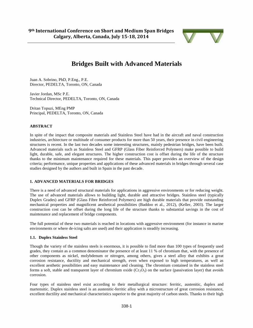
The tests were focused on determining the ultimate loads of the material under compressive and tensile forces
Furthermore the connections using adhesive or steel bolts have been analyzed Figure 5 shows some of the
performed tests to evaluate the capacity of the bolted connections Mechanisms of failure are due to shear-out failure
or bearing failure depending on the load and the distance of the bolt to the edge of the panel Design manual
provided by the GFRP supplier (Fiberline) is an excellent tool for designing the connections and the failure loads
predicted with the simplified formula is in good agreement with the failure loads obtained at the experimental test
Panels subjected to axial loads have an elastic behavior and they fail due to buckling instability that can be predicted
by the Euler critical load
The static and dynamic performance was a main concern during the design Users are highly sensitive to vibrations
and finishing details Both static and dynamic tests were performed and the obtained structural response was very
similar to the predicted one and met all the reference regulations
Figure 5 Load test to evaluate the capacity of bolted connections (left) and axial capacity of web panels (right)
338-8
25 Vilafant Pedestrian bridges
The high speed railway line connecting Barcelona and the French border crosses the Municipality of Vilafant 6 m
below the ground level To cross the sunken railroad two pedestrian bridges have been planned The structure with
one span of 46 m is monolithically connected with the abutments The use of unusual geometric shapes fabricated
using stainless-steel and GFRP are blended in an innovative fashion giving rise to an austere and elegant solution
(Figure 6) The two pedestrian bridges were completed in 2011
Figure 6 Vilafant pedestrian bridges
The two bridges have a main longitudinal span of 452 m and a width-deck of 4 m The structures are built-in on
both abutments The cross-section consists of two supported Vierendeel trusses made of duplex stainless steel grade
14162combined with double-sheets of GFRP as structural webs The height of the trusses is variable being 34 m at
the elastomeric support and 12 m at mid-span The bottom chord has an innovative shape prominent to the outward
of the bridge The chord has constant height of 350 mm and constant width of 376 mm The thickness of the bottom-
chord varies according with the structural needs The top-chord has a triangular-shape with constant height and
width of 350 mm The thickness of the chord is constant of 20 mm along the whole bridge The trusses located on
both ends of the bridge have the same triangular-shape as the top-chord previously mentioned
The cross- section width is 46 m and the walkway width is approximately 43 m The deck will be built using GFRP
panels 40 mm deep Two different transverse girders are used type I 300x150x15 mm made of GFRP and stainless-
steel girders The steel girders have a rectangular shape of 350x300x20mm The spacing between the GFRP is
1020 m and the steel girders are place among them every two trusses The both end transverse girders are also made
of stainless duplex steel The stainless steel girders are welded to the bottom chord on all the sides to provide lateral
stability
The connection between the bottom chord and GFRP transverse girders is made through bolt connection considered
as a pinned connection The GFRP panels located between the Vierendeel trusses consist of two plates with 4 mm
thickness The GFRP panels are connected to both chords with stainless-steel bolts The GFRP floor panel simply
supported on the floor girders and the connection is made with standard bolts which are specifically built for these
kinds of panels
338-9
The abutments of the bridge are made of reinforced concrete The height of the abutment is approximately 96
meters and it has been built in two different stages On the first stage the total height of the abutment is 810 meters
and a steel sheet has been left embedded for the posterior placing of the steel structure The final concreting is
carried out once the footbridge is located and welded to the steel bearing plate The width of the abutment is 56
meters Green walls aligned with the abutments help to integrate the footbridge with the surroundings
26 Tarragona Pedestrian bridges
The T-11 pedestrian bridges are a set of 4 similar pedestrian structures that cross the T-11 highway near Tarragona
Spain completed in 2013 The footbridges are located in different positions along T-11 highway and the two-span
continuous Vierendeel truss with span length varying between 195 m and 285 m (Figure 7) The typical cross-
section is 285 m wide with a free walkway of 212 m The pedestrian bridges have both curve layout and elevation
Figure 7 T-11 pedestrian bridges
The bottom chord has a trapezoidal shape with inclined webs to increase sun light reflection The thickness of the
bottom chord varies among the footbridges depending on the different spans and placing always the thickest over the
pile for having the higher negative moments The maximum thickness used is 18 mm and the minimum 12 mm The
top chord is considered as a structural member that works on tension or compression The top chord is a steel plate
35mm x 300 mm The handrail is made of polished stainless steel and it will be placed over the top chord
The deck is also built with two different kinds of transverse girders Typical floor beams are I 200 x 100 x10 GFRP
girders spaced at 11 m The connection between the chord and the GFRP girders is made through stainless steel
bolts which makes a pinned connection Steel floor girders with rectangular shape are placed every 44 m to increase
lateral stability of the floor system The two end transverse girders are also made of steel but the shape differs from
the ones located along the bridge These steel girders are welded to the bottom chord on all sides
The GRFP web panels located between the trusses consist of one single panel with 4 mm laminate-thickness This
panel is connected with a GRFP plank 4 mm thickness which is glued to the previous one with translucent epoxy
adhesive The GFRP floor panels are mounted over the girders and the connection is made with standard bolts
338-10
The lighting system is integrated inside the trusses giving a minimalist view and guidance for pedestrians along the
footbridge The access to the footbridge is improved by building concrete-ramps on both sides of the highway which
will fulfil the current accessibility requirements and will improve the functionality of the urban area
The end columns will support both the ramps and the cantilever for the footbridge The piers have a circular cross-
section 045 m in diameter and approximately 6 m height The central pier is placed on the central median of the
highway and it has a Y-shaped
3 CONCLUSIONS
Most of the fundamental advances in structural engineering have been related to the use of new materials The
increase in the use of advanced materials in bridge design can partially be attributed to the increasing awareness
from Public Administrations to use materials that require reduced maintenance in addition to having greater
mechanical resistance This paves the way for attractive bridge engineering
The bridges presented in this article illustrate the great possibilities offered by stainless steel and GFRP materials to
structural engineering Even if the cost of the stainless steel is higher than conventional materials (carbon steel and
concrete) an economical decision based on life cycle cost of the structure enhances structural solutions with
advanced materials thanks to the considerable economical savings from its reduced maintenance
4 REFERENCES
Baddoo N Iles D Dunca C and Houska C 2012 The Use of Stainless Steel in Bridge Structures Proceedings of the
International Bridge Conference Pittsburgh PA USA
Keller T 2003 Use of Fibre Reinforced Polymers in Bridge Construction Structural Engineering Documents IABSE
Zurich Switzerland
Baddoo N 2013 Structural Stainless Steel Steel Design Guide 27 American Institute of Steel Construction (AISC)
Chigago IL USA
Helzel M 2004 Pedestrian bridges in stainless steel (building series volume 7 First Edition 2004) Euro Inox
Luxembourg
ASCE 2011 Pre-Standard for LRFD of Pultruded Fiber Reinforced Polymer Structures American Society of Civil
Engineers USA
Introduction
The use of fibre-reinforced plastic pro-files in civil engineering structures has undergone a significant developmentover the last decade From the con-struction of the cable-stayed footbridgeat Aberfeldy UK (1992) to that of the Pontresina footbridge Switzerland(1997) some ten further bridges par-tially or entirely using composite ma-terials [1 2 and 3] have been reportedin technical literature Most of theserecent structures are truss-type bridgesusing glass-fibre-reinforced plastic(GFRP) pultruded profiles
The footbridge presented in this paperis located about 2 km from the city ofLleida in Spain and was built to crossa roadway a railway line and the newprojected high-speed railway line be-tween Madrid and Barcelona Theowners required a new pedestrianstructure with minimum maintenanceand which would be easy to erect Thefootbridge was completed in October2001
The proposed and accepted construc-tion solution resulted in an innovativedesign using GFRP pultruded profileswhich have no magnetic interactionwith the electrified railway line mini-mum maintenance costs and was easyto build (Fig 1) Thanks to its light-
ness it took only 3 hours to completethe erection of the bridge to its finalposition The principle factor contri-buting to the construction of this bridgewas the creative spirit of all those in-volved in this project
General description
A main problem was that of finding anappropriate structural form to spanthe required 38 m length using stan-dard GFRP profiles The final struc-ture is a double-tied arch of 38 m span-length with a rise of 62 m (spanrise 6)and 3 m wide (Fig 2) The arch config-uration was chosen to minimize service-ability problems due to the low modu-lus of elasticity of GFRP profiles The
arches are inclined 6deg to achieve amore pleasant appearance (Fig 3)The total weight of the bridge is approx-imately 19 t It is possible that it is thelongest span bridge in the world usingthis type of structure
All of the profiles are made of fibre-reinforced plastics using continuous E-glass fibres combined with wovenand complex mats with a minimumglass-fibre content of 50 The matrixis made of isophthalic polyester Themodulus of elasticity in the longitudi-nal direction ranges from 23ndash27 GPadepending on the type of profile Itstensile or compressive strength in thelongitudinal direction is 240 MPa andits strength in the transverse directionvaries from 50 to 70 MPa
Both arches and the tied longitudinalmembers present a rectangular hollowcross-section made up of two U 300 times90 times 15 mm profiles joined with gluedflat plates of 180 times 12 mm to form abeam tube (Fig 4) The supplier of theprofiles carried out full-scale testing
84 Advanced Materials Structural Engineering International 22002
Towards Advanced Composite Material FootbridgesJuan A Sobrino Dr Mordf Dolores G Pulido Civil Eng Pedelta Barcelona Spain
Fig 1 General view of the entire GFRP footbridge
Fig 2 Elevation and plan views of the footbridgeFig 3 Elevation and view of the footbridgefrom the west ramp
to verify the beam joints using the proposed epoxy adhesive In order toreduce horizontal deformation of thearches due to wind pressure these ele-ments are forked out into two branch-es using the same profiled sections(Fig 3)
The hangers are I-profiles of 160 times80 times 8 mm The arches are connectedby square tubes of 100 mm size and areof various thickness (6 to 8 mm)
The deck is made up of transverse I-beams of 200 times 100 times 10 mm spacedat 06 m and directly supporting the 4 cm thick deck panels which form thetransit or roadway surface A bracingsystem to avoid distortion was designedusing diagonal U-section members of160 times 48 times 8 mm as a typical cross-sec-tion (Fig 5)
The chief problem with GFRP struc-tures is the design construction and assembly of the joints due to the aniso-tropic behaviour of the FRP profilesAs a result of the lack of experience
with glued connections on bridges alljoints are bolted using stainless steelbrackets and bolts (Fig 6 and 7) Diag-onal elements were added in the de-sign joining the nodes of the archesand the tied longitudinal members toimprove the dynamic behaviour of thebridge To reduce its visual imagestainless steel cable elements of 12 mmin diameter were selected
Access to the arch bridge was createdusing reinforced concrete ramps con-ceived as a continuous beam of 10 mmaximum span-length and 06 m indepth The slope of the ramps is limit-ed to 8 to guarantee complete acces-sibility for disabled persons
Design criteria
Structural static and dynamic analyseswere carried out using a three-dimen-sional bar model and assuming elasticbehaviour
The design had to comply with the Serviceability Limit States required by the Spanish Bridge Design Code Thebridge has been designed for a nomi-nal uniform load of 4 kNm2 The par-tial safety factors for material proper-ties adopted to verify the UltimateLimit States were 2 for normal stress-es and 3 for shear stresses For buck-ling stability verification the meanmodulus of elasticity was reduced by afactor of 2 The design of most of theelements was governed by the LimitState of Deformation and in some ofthe elements of the arches by bucklingstability
Deflection under frequent loads (2kNm2) is about 24 mm (L1580) Staticand dynamic tests were performed be-fore the erection of the bridge in its final position During the static tests ndashusing 16 t water containers each equi-valent to 2 kNm2 mean load ndash the max-imum deflection reached was 26 mmResidual deflection was 7 mm and was
probably due to the adjustment of thebolts and connections The structuralbehaviour was practically linear (Fig 8and 9)
Special attention was given to the dy-namic behaviour First frequency (flex-ural mode) obtained in the analysiswas 269 Hz Maximum accelerationwas limited by introducing diagonal el-ements joining arches and longitudinaltied elements to obtain a stiffer struc-ture The first frequency measuredduring the dynamic test was 275 Hzand viscous damping was 25 to 3of critical damping
The parameters measured during thetest show that the structure is consider-ably stiffer than indicated by theoreti-cal predictions This is due to the pro-filed members having a higher defor-mation modulus than was presumed inthe design stage and also to the extrastiffness of the connections (which insome cases were rejected in the designstage)
To avoid fractures in the rectangulartubes of the arches and the tied longi-tudinal beams some of the joints werefilled with a mortar of sand and resinIn the diagonal elements PVC blockswere used for the same purpose Dueto the complex geometry in some cas-es it was impossible to fill them with ei-ther mortar or PVC blocks It shouldbe noted that the higher temperaturesinduced by the use of considerable vol-umes of resin mortar may end up dam-aging the profiles Detailed analyses ofjoints without mortar were carried outusing finite element models includingsteel brackets The purpose was toquantify the stresses and deformationsproduced by the pressure induced bythe bolts
Construction
The structural elements were manu-factured in Denmark and transported
Structural Engineering International 22002 Advanced Materials 85
Fig 4 Arch profiles Fig 6 Connections between floor profiles Fig 7 Connections in the arch
Fig 5 Floor system
to Spain for assembly The maximumlength of the elements transported is 9 m The bridge construction processwas as follows
ndash construction of the reinforced con-crete end-ramps
ndash construction of temporary columnsnext to the ramps so as to permitmounting the complete FRP structure
ndash the assembly of the deckrsquos members ndash assembly of the vertical elements
and archesndash the painting of the FRP profiles (in
white and blue)ndash the partial demolition of the tempo-
rary columns so as to transfer theloads to the end piers reproducing thefinal support configuration to permitperforming static and dynamic tests
ndash the installation of the structure span-ning a busy railway line within a 3hour time-limit (Fig 10)
The assembly was carried out by 8 peo-ple working over 3 months The lowweight of the bridge coupled with thepossibility of using simple hand toolsfor machining the required adjustmentsmade the bridge assembly much easi-er Some difficulties arose during theerection of the arches due to theircomplex geometry requiring minimumtolerances in the length of the profilesand the geometry of the steel bracketsThis resulted in some adjustments on site
Conclusions
The positive interaction between theadministration the contractor the sub-contractors and the design engineerswas the principle factor in making thisinnovative footbridge a reality
The range of application of advancedfibre-composite materials is very wideparticularly when minimum mainte-nance lightness transportation facili-ties no magnetic interaction or quickerection times are required The initialcost due to material supply and designis higher when compared with tradi-tional steel-based solutions howeverconsiderable savings are made in con-struction and maintenance
The development and future of advanc-ed composite materials for architectur-al and civil engineering structural ap-plications will depend basically on thedevelopment of new structural formsand element-joining techniques Struc-tural codes could help to spread theuse of full advanced composite plasticstructures but regulations of thesestandard documents could also have anegative effect on the creativity ofstructural engineers
Engineers possess a magnificent po-tential knowledge regarding the be-haviour of materials and structures butaesthetics should also be taken into account as well as structural perfor-mance and economy All this couldeasily be done by simply making an ex-tra effort during the conceptual designstage This footbridge demonstratesthat advanced composite materials canbe easily introduced into most types ofstructural forms thus taking advantageof their outstanding mechanical andchemical properties
References
[1] KELLER T Towards Structural Forms forComposite Fibre Materials Structural Engineer-ing International IABSE Zurich Vol 9 No 41999 pp 297ndash300
[2] BURGOYNE CJ Advanced Composites inCivil Engineering in Europe Structural Engineer-ing International IABSE Zurich Vol 9 No 41999 pp 267ndash273
[3] BRAESTRUP MW Footbridge Constructedfrom Glass-fibre-reinforced Profiles DenmarkStructural Engineering International IABSEZurich Vol 9 No 4 1999 pp 256ndash258
86 Advanced Materials Structural Engineering International 22002
App
lied
test
load
(kp
m2 )
250
200
150
100
50
00 5 10 15 20 25 30
Deflection at mid-span (mm)
Fig 8 Mid-span deflection measured dur-ing static test
Fig 9 General view of the load static testmade before the final erection of the bridge
Fig 10 Erection of the bridge
SEI Data Block
OwnerGestor de Infraestructuras Ferroviarias
Structural designJuan A Sobrino Javier Jordaacuten and Mordf Dolores G Pulido civil engineersPEDELTA
ContractorUTE Lleida RUBAU Construccions ndashCOPASA Spain
SubcontractorFiberline Denmark
Total cost (USD) 325 000 USD
Cost of composite structure (USD) 270 000 USD (2350 USDm2)
Service date October 2001
96 Reports Structural Engineering International 22006
Summary
One of the most interesting things in the development of bridge engineering is the exploration of new structural materials like for example stainless steel with its excellent mechanical properties magnificent durability and aesthetic possibilities The use of new structural materials in bridge engineering constitutes a metaphor to the innovation and at the same time a vindication of the enormous value of en-gineering as an impelling element of the development and progress of the society building bridges for the future and paving the way to the ones that follow
This paper describes a composite stainless steel road bridge recently built in Cala Galdana (Menorca) being the first road bridge in Europe and probably world-wide using stainless steel for the structure
its high resistance to corrosion from the marine atmosphere as the solution that better responded to the ownerrsquos requirements The new bridge has be-come a landmark for the island thanks to the technological innovation of using stainless steel
The solution has been designed fulfillingfour explicit objectives environmentalrespect (during construction and in serv-ice recovery of the old river bed) high durability minimum maintenance and a symbol of advanced technology (Fig 1)
Stainless Steel as Structural Material Though the variety of the stainless steels is enormous it is possible to find more than 100 types of frequently used grades They contain as a common denominator at least 11 of chromium that with the presence of other compo-nents as nickel molybdenum or nitro-gen among others gives a steel alloy that exhibits a great corrosion resistance ductility and mechanical strength even when exposed to high temperatures as well as excellent aesthetic possibilities and easy maintenance and cleaning The chromium contained in the stainless steel forms a soft stable and transpar-ent layer of chromium oxide (Cr2O3) on the surface (passivation layer) that avoids corrosion
Four types of stainless steel exist accord-ing to their metallurgical structure fer-ritic austenitic duplex and martensitic Duplex stainless steel is an austen-itic-ferritic alloy with a microstruc ture of great corrosion resistance excellent
Stainless Steel Road Bridge in Menorca Spain Juan A Sobrino Dr Eng PEDELTA Barcelona Spain
Fig 1 General view of the bridge over Algendar river
Introduction
The island of Menorca was declared a unique biosphere by UNESCO thanks to the natural surroundings and its rich historical and ethnological heritage an outdoor museum Cala Galdana is with its shell form 450 m long and 45 m wide one of the most beautiful beaches of the island The surround-ings are only partially urbanized and they contribute to the attractiveness of the island to tourists
Algendar river terminates at the beach of Cala Galdana and it has been crossed for the last 30 years via a rein-forced concrete bridge approximately 18 m long Due to its advanced state of corrosion induced by the marine atmosphere and an important support settlement in one of the abutments the owner decided to substitute it by a new bridge The new bridge should span the entire width of the old river more than 40 m fitting harmoniously in the natural surroundings and making use of a material with great durability and minimum maintenance
During the design process different structural and material alternatives were analysed Eventually a duplex stainlesssteel arch structure was chosen due to
Report X-110indd 96Report X-110indd 96 42106 15654 PM42106 15654 PM
Structural Engineering International 22006 Reports 97
duc tility and mechanical characteristics superior to the great majority of carbon steels Thanks to their high strength duplex steels are suitable for applica-tion in bridges and footbridges [1] [2] With the existence of a wide range of duplex steel grades the selection of the most suitable type clearly depends on the ambient aggressiveness type of cor-rosion mechanical properties types of surface finish and so forth
Stainless steel unlike the conventional carbon steels presents a mechanical nonlinear behaviour even under re-duced stress values without having an elastic limit strength clearly defined However the stress value associated to a strain of 02 has been adopted as a conventional yield stress (f02) For hot rolled plate and taking as an example the duplex steel 14462 used in the bridge of Cala Galdana (Menorca) de-scribed in this article mechanical prop-erties of the material are summarized in Table 1 comparing it with the stain-less steel 14404 (ASTM 316 L) and the carbon steel S-355
Surprisingly in spite of the impact that stainless steel has had in industry naval construction architecture or consumer products for more than 50 years its presence in civil engineering and in particular in structures has been virtu-ally nonexistent until just a few years ago Nevertheless there have already been built some very interesting foot-bridges [2]
Bridge Description
The overall length of the bridge is 55 m with a 13 m wide deck The deck allocates 2 lanes of road traffic (7 m) and two lateral sidewalks each 2 m wide that allow the pedestrians to enjoy the panoramic views from an excellent location
The main structure consists of two par-allel arches with an intermediate deck The arches and the deck join at the
abutments by means of an inclined strut that takes the horizontal component of the arch axial force and consequently significant horizontal forces are not transferred to the abutments
Substructure
The soil conditions for foundations of the two abutments are very differ-ent Whereas in abutment 1 on the right riverside the resistant substra-tum (Miocene limestone) is at a depth of more than 40 m in the opposite abutment the limestone appears at a depth of only about 4 m
Abutment 1 is a big reinforced concrete block with a footprint of 114 95 m2 and 38 m high supported on 14 prefab-ricated concrete piles of 04 04 m2 and 42 m long As an aesthetic feature the visible surfaces have been inclined to integrate them into the embankment and horizontal shallow channels have been spaced at 15 cm intervals to avoid large smooth surfaces Abutment 2 is directly founded on surface limestone Its dimensions are greater than those of Abutment 1 with a footprint of 115 13 m2 and 72 m high
Each abutment supports the bases of the parallel arches and the two longi-tudinal beams of the deck The arches are supported on POT bearings and the beams on laminated elastomeric bearings In order to avoid the vertical displacement of the deck with respect to the abutment four vertical anchor-ages (constituted by four unbonded post-tensioned cables with 12 strands of 15 mm) were applied The inclined struts that connect the base of the arch and the end of the deck have been re-cessed into the front face of the abut-ment (Fig 2)
Structure
The structural scheme is constituted by two parallel arches with a free span of 45 m and an intermediate deck The
Fig 2 Abutment 2 view of the completed element
2 2 2 2
100
210 100 100 210700
1320
700 100
Fig 3 Typical deck cross-section
Fig 4 View of bridge from below
Mechanical property Stainless steel Stainless steel 14404 Carbon steel S-355 Stainless steel Duplex 14462 (ASTM-316L) Duplex 14462 (Minimum specified (used in Cala values) Galdana Bridge)
Tensile strength (MPa) 640 530 510 767
Conventional yield stress f02 (MPa) 460 220 355 535
Elongation () 25 40 gt15 35
Table 1 Mechanical properties at 20deg C Minimum specified values of three different steels
main structure is made of duplex stain-less steel grade 14462 which exhibits a high resistance to corrosion by chlo-rides The deck is made of reinforced concrete connected to a series of trans-verse beams (Fig 3)
The arches rise to a total of 6 m (rela-tion spanrise 75) and they are tied to the deck by means of two connected longitudinal beams These longitudinal beams are again connected by means of transverse beams (Fig 4)
Report X-110indd 97Report X-110indd 97 42106 15703 PM42106 15703 PM
98 Reports Structural Engineering International 22006
The arches have a triangular cross-section (Fig 5) with a central web Their depth is 070 m - constant throughout their overall length However the width of the section varies between 070 and 1 m The central web of the section is transformed into a cellular plate that allows connecting the arch with the longitudinal deck beam The longitudi-nal beams are rectangular hollow sec-tions of 1 m 05 m constituted by plates with varying thicknesses between 15 and 25 mm In the central zone with the arch above the deck these beams have a central web that is connected to the web of the arch allowing direct transfer of the vertical loads of the lon-gitudinal beam to the arch
The transverse beams spaced at 2 m are formed by rectangular cross-sections 025 m wide and with a variable depth varying between 050 and 057 m (to obtain) the deck cross-slope of 2 constituted by plates of 10 and 12 mm These beams are structurally connected to the reinforced concrete slab hav-ing an average thickness of 030 m by means of Bernold type studs of 20 mm in diameter
In order not to transfer the horizontal component of the arch axial force to the abutments two inclined strutsndashconnecting the base of the arch and the end of the longitudinal beam have been designed which are anchored at the top of the abutments The struts have a rectangular hollow cross-sectionwith outer dimensions of 1 m 05 m formed by plates of 20 and 25 mm thickness internally stiffened in both longitudinal and transverse directions
One of the most difficult connections is the one between the inclined strut (of rectangular cross-section) and the
base of the arch (of triangular cross-section) This element is directly sup-ported by the pot bearing (Fig 6) and is strongly stiffened
The lateral sidewalks are separated from the road by the arches (Fig 4) These sidewalks are supported by means of a reinforced concrete slab supported on transverse cantilever ribs every 2 m con-nected to the longitudinal beam
The railing has been designed with wood en banisters with an elliptical
cross-section supported by posts of curved geometry made of stainless steel every 2 m joined to the end of the trans-verse ribs as if it was only one piece
Structural Behaviour
The analysis and design of the bridge has been carried out using the criteria from Eurocode 3 part 14 [3] including consultation of bibliography and exist-ing recommendations from European associations [4] [5]
VARIABLE 7001000
50deg
58deg
25
20
25
15
1515
15
470
500
1000
25
20
ARCH
LONGITUDINAL BEAM
Fig 5 Typical cross-section of the arch and longitudinal beam
30 3025
40
40
40
462 30477
462477
955
25
2525
455
455
40
40
40
40
25
2513
813
812
912
913
813
825
2525
2525
1000
500
40
40
40
25
25
336
336 358
25 2530
40
1000
40
580
40
67725
40
40
40
698
50˚
Fig 6 Joint between strut and arch
Report X-110indd 98Report X-110indd 98 42106 15718 PM42106 15718 PM
Structural Engineering International 22006 Reports 99
The structural behaviour of the bridge is a self-anchored arch that does not transfer horizontal reaction forces to the foundations In Fig 7 the reactions as well as the transfer of axial internal forces among the main elements have been illustrated
The structural calculations have been made with a standard finite element programme developing diverse mod-els or adjustments to contemplate the phenomena of softening of the stainless steel under stresses over 60 of the conventional elastic limit(02 proof stress f02) and the crack-ing effects in certain zones of the re-inforced concrete slab The general model combines bar type and shell elements
The steel stresses have been limited to 75 of f02 for the combination of fre-quent loads and to 90 of f02 for the characteristic combination
Construction Process
The works of the bridge began in Octo-ber 2004 starting with the demolition of the existing bridge and were completed the first week of June 2005
Processes of construction with stain-less steel are similar to those used for carbon steels but non identical adopting specific techniques for cut-ting bending forming welding and finishing Welding consumables must also be specific to the stainless steel grade to guarantee equal mechanical and corrosion properties to those of the base material
Welding techniques used were with shielded metal arc welding (SMAW) using an inert gas with covered elec-trode metal inert gas (MIG) flux cored arc welding (FCAW) and submerged arc welding (SAW) [6] without preheat-ing and not exceeding a temperature of 150deg C between two consecutive passes Welding produces an oxidation of the base metal and a significant change of surface colour and the appearance tex-ture that should be corrected by means of a later treatment This aspect is essential
to guarantee the desired surface fin-ish colour and texture After removing solid slag in the weld a chemical treat-ment (pickling) has been applied by means of a pickling paste constituted by acids hydrofluoric and nitric Its application during 4 hours allows the removing of contaminants and oxides generated during welding and facili-tate the formation of the passive layer Finally in order to guarantee a uniform finished surface of the pieces a blasting treatment with high pressure using glass micro-spheres has been applied
The contact of the stainless steel with other metals during the manufacturing or in its definitive location can cause galvanic corrosion For this reason man-ufacturing and assembly of the structur-al parts was carried out in zones where it does not come in contact with car-bon steel
The bridge was assembled on site by means of crane placing 8 sections on temporary supports for later welding (Fig 8)
Once the construction of the bridge was completed a static load test was carried out considering different load stages
and measuring essentially verticaldeflections The structure presents a stiffer behaviour than expected The measured deflections were about 80 of the theoretical values obtained with an average value of the modulus of elasticity of E = 200 GPa The de-flections recovered elastically practi-cally in their totality Considering the results of the quality control of the steel which affirms that the secant modulus of elasticity at 02 is 16 superior to the one considered in the calculation model explains the difference of deflec-tions measured in the test of load
An exhaustive quality control process has been undertaken increased by the innovative character of the material having intensified all the internal con-trols of the welds both off and on site with techniques such as ultrasonic test-ing X-rays and magnetic particles The measured values of the stainless steel mechanical properties at the quality control turned out to be greater than the ones specified in the design and the Codes (Table 1)
Conclusion
The fundamental advances in struc-tural engineering have always been related to the use of new materials The increase in the use of advanced materials in bridge design can partially be attributed to the increasing aware-ness from Public Administrations to use materials that require reducedmaintenance in addition to having
Fig 8 Assembly of the steel structure
minus6760 kN
minus10160 kN minus11140 kN
minus4370 kN5070 kN
8130 kN
4450 kN
Fig 7 Distribution of reactions and axial forces (kN) in the most unfavourable service combination
Report X-110indd 99Report X-110indd 99 42106 15719 PM42106 15719 PM
100 Reports Structural Engineering International 22006
greater mechanical resistance This opens up an attractive way for bridge engineering
Cala Galdana Bridge a landmark of Menorca illustrates the great possibili-ties offered by stainless steel to struc-tural engineering Even if the cost of the stainless steel is sensibly superior to that of conventional materials (car-bon steel and concrete) an economical decision based on life cycle cost of the structure enhances structural solutions with stainless steel thanks to the con-siderable economical saving from its reduced maintenance
Acknowledgements
The positive interaction between the client contractor subcontractors and the consulting engineers has made this innovating project a reality Spe-cial thanks to the Consell Insular de
Menorca for its support and promo-tion of the application of innovative technologies to bridge engineering
References
[1] PASCUAL J RIPA T Y MILLANES F ldquoSome singularities of stainless steel as structural materialrdquo (in Spanish) CEA 2004 Structural Steel Congress pp 229ndash238 La Coruna (Spain) 2004
[2] Eurinox ldquoPedestrian bridges in stainless steelrdquo building series volume 7 Luxembourg 2004
[3] ENV 1993-14 ldquoEurocode 3 Design of steel structures Supplementary rules for stainless steelrdquo
[4] Eurinox ldquoDesign manual for structural stain-less steel (2nd edition)rdquo building series volume 3 Luxembourg 2002
[5] The Steel Construction Institute ldquoStructural design of stainless steelrdquo SCI Publication P291 Ascot UK 2001
[6] American Welding Society ldquoWelding Hand-bookrdquo Volumes 1 and 2 Miami FL 2004
SEI Data Block
Owner Consell Insular de Menorca Mobility Directorate
Design and Technical Assistance During ConstructionPEDELTA Juan A Sobrino Juan V Tirado Javier Jordan Xavier Martinez (Civil Engineers) and Agusti Garcia (Industrial Engineer)
ContractorFERROVIAL
SubcontractorsOUTOKUMPU supply and prepara-tion of plates ASCAMON steel fabricator (main subcontractor) MEKANO-4 stainless steel bearings
Stainless Steel (t) 165 (225 Kgm2)
Total Cost of the Bridge (EUR millions) 26 (including accesses)
Service Date June 2005
Fiberline Composites ASNr Bjertvej 88DK 6000 KoldingTel +45 70 13 77 13Fax +45 70 13 77 14fiberlinefiberlinecomwwwfiberlinecomldquoFootbridge Award 2005rdquo
The journal Bridge design amp engineering
Installed in just three hoursThe award-winning GRP footbridge near Lleida Spain was custom-built to demanding specifications of the Spanish railway authorities for minimal maintenance fast installation and zero magnetic interference
As the bridge would cross a major rail link minimising disruption to services was a key priority Accordingly the bridge was assembled at the track side and then craned into place resulting in a railway possession time of only three hours for the complete erection
The bridge was designed by the Spanish engineering consultant Pedelta and built using structural components supplied by Fiberline Composites
Report X-110indd 100Report X-110indd 100 42106 15727 PM42106 15727 PM

338-2
strength duplex steels are suitable for application in bridges and pedestrian bridges (Baddoo 2013) (Helzel 2004)
With the existence of a wide range of duplex steel grades the selection of the most suitable type clearly depends on
the ambient aggressiveness type of corrosion mechanical properties types of surface finish and so forth
Stainless steel unlike the conventional carbon steels presents a mechanical nonlinear behaviour even under
reduced stress values without having an elastic limit strength clearly defined However the stress value associated
to a strain of 02 has been adopted as a conventional yield stress f02 (Baddoo 2013) Processes of construction
with stainless steel are similar to those used for carbon steels but not identical adopting specific techniques for
cutting bending forming welding and finishing Welding consumables must also be specific to the stainless steel
grade to guarantee equal mechanical and corrosion properties to those of the base material
12 Glass Fiber Reinforced Polymers (GFRP)
FRP materials are frequently used in aerospace marine automobile and leisure industries when high mechanical
strength light weight and corrosion resistance are needed Glass Fiber Reinforced Polymers are composite materials
made of Glass fibers (long or short fibers) on a polymeric matrix (usually isophthalic polyester vinylester epoxi or
phenol) Typically the matrix has low strength and modulus of elasticity with high ductility and fibers (the
reinforcement) provide high mechanical properties to the composite material although they exhibit a brittle
behaviour The arrangement of the fibers may be random or with a preferred orientation The mechanical and
chemical properties of the material depend on the properties arrangement and proportions of the constituents and
are strongly influenced by the fabrication process (Keller 2003) (ASCE 2011)
The use of fibre-reinforced plastic profiles in civil engineering structures has undergone a significant development
during the 90rsquos From the construction of the cable-stayed footbridge at Aberfeldy - UK 1992- to that of the
Pontresina footbridge -Switzerland 1997- several hundred further bridges have been built in the past twenty years
(mostly pedestrian bridges) Most of these recent structures are truss-type bridges using GFRP pultruded profiles
Pultrusion is a fabrication process to produce composite profiles with constant cross-sections and mechanical
properties Typically GFRP pultruded profiles have modulus of elasticity ranging from 23 to 28 GPa and flexural
strength around 240 MPa in the longitudinal direction The density of the GFRP is usually 18 (ASCE 2011)
GFRP exhibits excellent mechanical properties and light weight but due to its relatively low modulus of elasticity
GFRP structures are flexible and sensitive to dynamic effects Combination of GFRP and steel provides stiff
structures and still a reduced weight as has been proven in recent structures included in this article
2 CASE STUDIES
21 Minorca stainless steel vehicular bridge
This is the worldrsquos first duplex stainless steel vehicular bridge The bridge built in 2005 crosses the Algendar River
in Cala Galdana (Minorca Spain) and replaced an existing reinforced concrete bridge that experienced a significant
deterioration after 30 years of exposure to a marine environment After 9 years of service the new bridge is in
excellent conditions and has not undergone any corrosion
During the design process different structural and material alternatives were analysed Finally a duplex stainless
steel arch structure was chosen due to its high resistance to corrosion from the marine atmosphere as the solution
that better responded to the ownerrsquos requirements The new bridge has become a landmark for the island thanks to
the technological innovation of using stainless steel
The overall length of the bridge is 55 m with a 13 m wide deck The deck allocates 2 lanes of road traffic (7 m) and
two lateral sidewalks each 2 m wide that allow the pedestrians to enjoy the panoramic views from an excellent
location (Figure 1) The main structure consists of two parallel arches with an intermediate deck The arches and the
deck join at the abutments by means of an inclined strut that takes the horizontal component of the arch axial force
and consequently significant horizontal forces are not transferred to the abutments
338-3
Figure 1 Minorca Duplex Stainless Steel Bridge
The structural scheme is constituted by two parallel arches with a free span of 45 m and an intermediate deck The
main structure is made of duplex stainless steel grade 14462 which exhibits a high resistance to corrosion by
chlorides The deck is made of reinforced concrete connected to a series of transverse beams The arches rise to a
total of 6 m (relation spanrise = 75) and they are tied to the deck by means of two connected longitudinal beams
These longitudinal beams are again connected by means of transverse beams The arches have a triangular cross-
section with a central web Their depth is 070 m - constant throughout their overall length However the width of
the section varies between 07 and 1 m The central web of the section is transformed into a cellular plate that allows
connecting the arch with the longitudinal deck beam The longitudinal beams are rectangular hollow sections of 1 m
x 05 m constituted by plates with varying thicknesses between 15 and 25 mm In the central zone with the arch
above the deck these beams have a central web that is connected to the web of the arch allowing direct transfer of
the vertical loads of the longitudinal beam to the arch The transverse beams spaced at 2m are formed by
rectangular cross-sections 025 m wide and with a variable depth varying between 050 and 057 m (to obtain) the
deck cross-slope of 2) constituted by plates of 10 and 12 mm These beams are structurally connected to the
reinforced concrete slab having an average thickness of 030 m by means of Bernold type studs of 20 mm in
diameter
In order not to transmit the horizontal component of the arch axial force to the abutments two inclined struts ndash
connecting the base of the arch and the end of the longitudinal beam have been designed which are anchored at the
top of the abutments The struts have a rectangular hollow cross-section with outer dimensions of 1 m x 05 m
formed by plates of 20 and 25 mm thickness internally stiffened in both longitudinal and transverse directions
The lateral sidewalks are separated from the road by the arches These sidewalks are supported by means of a
reinforced concrete slab supported on transverse cantilever ribs every 2 m connected to the longitudinal beam
22 Sant Fruitoacutes Pedestrian bridge
Sant Fruitoacutes is a small town with more than ten centuries of history Located 59km from Barcelona close to
Manresa it occupies a strategic position for road communications in Catalonia The 20th century economic boost
and population growth have led to the creation of new residential areas around the historic core and consequently of
new public infrastructures The neighbourhood of Rosaleda a new residential area of Sant Fruitoacutes which hosts more
than 6 of its population is separated from a commercial district and the rest of the town by the N-141C a national
road The crossing of this road has caused many accidents some of them with casualties on the last few years The
Municipality decided to eliminate this risk by building a pedestrian bridge Additionally to its main function the
structure should be a new landmark and a gateway to the town representing its dynamic and innovative nature
338-4
The location of the bridge was fixed by the owner to provide a direct access to a bus stop The bridge built in 2009
crosses the N-141C road with a vertical clearance of 55m connecting areas with almost a difference of 6m in
elevation (Figure 2)
Figure 2 Sant Fruitos pedestrian bridge
The use of a bow-string reinterpretation - a classical structure as main element - and the stainless steel and GFRP
(glass fibre reinforced polymer) ndash high-performance and structurally innovative materials ndash are the key concepts
The leaned arch creates a dynamic and tense feeling and joins the deck for greater structural efficiency The
structure is sober very transparent and simple yet very expressive thanks to the use of extremely slender elements
and the arch geometry The crossing is now accessible to disabled people and bicycles by the slender concrete stairs
and panoramic lift on the residential side and the embankment stairsramps and stairs on the other
The structure with an overall length of 55 m is a tied arch with an intermediate deck The main components are
made of duplex stainless-steel The 40m span arch has a triangular section almost equilateral only 045m high and
it is tilted in plan and elevation forming an angle of 30 degrees with the vertical plan The arch cross-section is
fabricated with 20mm steel plates The 3m wide deck consists of a longitudinal trapezoidal box girder with ribs The
box cross-section is made of 10mm thickness plates Its shape is almost triangular 160m wide with constant depth
of 06 m The webs are 015 and 060m in height The 140m long ribs have a variable depth between 009 and
015m The deck is connected to the arch at one of the ends (elevator side) and in one intermediate section (36 m
from the elevator side) Stainless steel bars hangers 28mm in diameter spaced every 3m connect the deck and the
arch
The arch is supported in the elevator structure and on the other side rest over a small pier To not transmit any
horizontal force to the pierrsquos foundation an inclined strut element connects the end of the arch 5 m below the deck
level to the deck creating a V shape below the deck The light arch and the deck connected through hangers define
one of the most characteristic features of the structure a very attractive visual lightness and slenderness
The 14162 duplex stainless steel used in this footbridge contains less nickel than other duplex stainless types
Therefore its price is less variable and much lower than other duplex steels It is suitable for environments with an
average level of aggressiveness and it has a conventional yield strength of 480 MPa (more than 35 those of S355
carbon steel)
The deck consists of GFRP panels 05m wide 40mm in depth simply supported on the ribs or on the box girder To
avoid sliding these panels have a quartz sand surface coating
338-5
The dynamic test was conducted with people walking running or jumping (1 to 9 people) including eccentric load
cases 21 different load cases were defined covering a wide range of probable situations The response of the bridge
to dynamic load met the regulations and was very similar to the results of the dynamic calculation Measured
critical damping ratio is 00127
23 Lleida Pedestrian bridge over the High Speed Rail
This pedestrian bridge shown in Figure 3 is located 3 km from the city of Lleida (Spain) and was built in 2001 to
cross an already existing roadway a railway line and the new projected high-speed rail-way line between Madrid
and Barcelona The owners required a new pedestrian structure with minimum maintenance and which would be
easy to erect At the time of construction it was the first arch made of GFRP and the longest span made of standard
GFRP pultruded profiles After 12 years of service the bridge is in excellent condition and has not required any
maintenance
The most significant issue was that of finding an appropriate structural form to span the required 38 m of length
using standard GFRP profiles The final structure is a double-tied arch of 38 m span-length having a rise of 62 m
(spanrise 6) and 3 m wide The total weight of the bridge is approximately 19 Tons (Figure 3)
Figure 3 Lleida GFRP pedestrian bridge
All the profiles are made of fibre-reinforced plastics using continuous E-glass fibres combined with woven and
complex mats having a minimum glass-fibre content of 50 The matrix is made of isophthalic polyester The
modulus of elasticity in the longitudinal direction ranges from 23-27 GPa depending on the type of profile Its
tensile or compressive strength in the longitudinal direction is 240 MPa and its strength in the transverse direction
varies from 50-70 MPa
The arch configuration was chosen so as to minimize serviceability problems due to the low modulus of elasticity of
GFRP profiles The arches have been inclined by 6 to achieve a more expressive appearance Both arches and the
tied longitudinal members present a rectangular hollow cross-section made up of two U 300x90x15mm profiles
joined with glued flat plates of 180x12 mm so as to form a hollow rectangular tube The supplier of the profiles
carried out full-scale testing to verify the beam joints using the proposed epoxy adhesive In order to reduce
horizontal deformation of the arches due to wind pressure these elements are forked out into two branches using the
same profiled sections
The hangers are I-profiles of 160 x 80 x 8 The arches are connected by square tubes of 100 mm size and having
various thicknesses (6-8 mm) The deck is made up of transverse I-beams of 200x100x10 mm spaced at 06 m from
one another and they directly support the 4 cm thick deck panels that form the transit or roadway surface A bracing
system to avoid distortion was designed using diagonal U-section members of 160x48x8 mm as a typical cross-
section
338-6
All the above-mentioned structural elements are made of pultruded glass-fibre composite materials which were
manufactured in Denmark and transported to Spain to be assembled here The maximum length of the elements
transported is 9 m The chief problem with GFRP structures is the design construction and assembly of the joints
due to the anisotropic behaviour of the profiled members As a result of the lack of experience with glued
connections on bridges all joints are bolted using stainless steel brackets and bolts Diagonal elements were added
in the design joining the nodes of the arches and the tied longitudinal members to improve the dynamic behaviour
of the bridge To reduce its visual image stainless steel cable elements of 12 mm in diameter were selected
Access to the arch bridge is designed with reinforced concrete ramps conceived as a continuous beam of 10 m
maximum span-length and 06 m in depth The slope of the ramps is limited to 8 so as to guarantee complete
accessibility to disabled persons
24 Zumaia Pedestrian bridge
This pedestrian bridge is the first hybrid structure made up of Stainless-Steel and GFRP The bridge is located in
Zumaia a small town of Guipuzkoa (Basque Country Spain) In 2007 we were awarded to put forward the design of
a pedestrian bridge over Narrondo River connecting a public school and some sport facilities on the other side of the
river
The idea was to design a bridge that enhances the natural value of the River understanding its environment instead
of creating a useless or spectacular landmark bridge The proposal is a pure and sober structure but with an
innovating and challenging spirit As the pedestrian bridge is located in a corrosive environment due to its proximity
to the sea (less than 400 m) the selection of materials with high corrosion resistance has been crucial
The pedestrian bridge at Zumaia is the first bridge in combining two high performance materials stainless steel
(grade 14462) and composites (GFRP) in composite action The bridge crosses a 28 m long channel with a 5 m
wide deck The structural outline consists of two Vierendeel trusses that function as guardrail in which the lateral
lighting and handrail are integrated A hybrid structure combining duplex stainless steel and was chosen due to its
high resistance to corrosion from the marine atmosphere and lightness as the solution that better responded to the
ownerrsquos requirements (Figure 4)
Figure 4 Zumaia pedestrian bridge
The deck allocates a 2 m wide bicycle lane and a 3 m wide sidewalk The structural scheme is constituted by two
Vierendeel trusses with the main members in duplex stainless-steel parallel with a free span of 28 m and a
suspended 5 m wide deck The main structure is made of duplex stainless steel grade 14462 which exhibits a high
resistance to corrosion by chlorides The deckrsquos design concept is very simple in order to make the construction
easier and to reduce the number of profile types The deck is made of GFRP pultruded panels (40 mm depth)
supported on a series of transverse GFRP or Stainless-steel beams spaced at 1 m The planks used for the railing
and for the pavement are translucent to emphasize the lightness appearance
338-7
Longitudinal top chords consist of a plate of 300x28 mm the bottom chords have a rectangular cross-section 360
mm wide with variable depth between 300 and 400 mm made of plates 12 mm thickness Transverse beams spaced
at 1 m are formed by GFRP I-beams with a 300 mm depth except four of them which are made in stainless-steel
All connections between stainless steel members and GFRP beams or panels are bolted using stainless steel bolts
and brackets of the same material The vertical posts have an open Pi-cross-section made of stainless steel plates
The post integrates the lighting system The railing is made of banister wood supported on steel plates
The analysis and design of the bridge has been carried out using the criteria from Eurocode-3 part 14 including
existing European recommendations The ultimate limit state (ULS) requirements have been checked in all the
structural members of the bridge such as chords transverse girders and Vierendeel trusses The main issue for the
ULS verification is the composite collaboration of the GFRP panels and the steel members The principal objection
of using this combination is the lack of ductile behavior of the panels in comparison with the steel ductility The
available information on this issues remains insufficient due to the main researchers are still carried out on other
fields Due to that the ultimate limit state verification on the trusses has been done without considering the GFRP
web panel collaboration
The collaboration between the trusses and the GFRP panels has been considered for the verification of deflection or
vibration Serviceability Limit States GFRP elements provide a large damping compared to steel (about 2-3 of the
critical damping) and this is very beneficial for the dynamic behavior of such light structures
An intense experimental research was done during the construction of Zumaia Bridge The main goal of this
research is to improve the current knowledge on this innovative material As we have mentioned previously there
are still uncertainties on the behavior of this material when used on structures
The tests were focused on determining the ultimate loads of the material under compressive and tensile forces
Furthermore the connections using adhesive or steel bolts have been analyzed Figure 5 shows some of the
performed tests to evaluate the capacity of the bolted connections Mechanisms of failure are due to shear-out failure
or bearing failure depending on the load and the distance of the bolt to the edge of the panel Design manual
provided by the GFRP supplier (Fiberline) is an excellent tool for designing the connections and the failure loads
predicted with the simplified formula is in good agreement with the failure loads obtained at the experimental test
Panels subjected to axial loads have an elastic behavior and they fail due to buckling instability that can be predicted
by the Euler critical load
The static and dynamic performance was a main concern during the design Users are highly sensitive to vibrations
and finishing details Both static and dynamic tests were performed and the obtained structural response was very
similar to the predicted one and met all the reference regulations
Figure 5 Load test to evaluate the capacity of bolted connections (left) and axial capacity of web panels (right)
338-8
25 Vilafant Pedestrian bridges
The high speed railway line connecting Barcelona and the French border crosses the Municipality of Vilafant 6 m
below the ground level To cross the sunken railroad two pedestrian bridges have been planned The structure with
one span of 46 m is monolithically connected with the abutments The use of unusual geometric shapes fabricated
using stainless-steel and GFRP are blended in an innovative fashion giving rise to an austere and elegant solution
(Figure 6) The two pedestrian bridges were completed in 2011
Figure 6 Vilafant pedestrian bridges
The two bridges have a main longitudinal span of 452 m and a width-deck of 4 m The structures are built-in on
both abutments The cross-section consists of two supported Vierendeel trusses made of duplex stainless steel grade
14162combined with double-sheets of GFRP as structural webs The height of the trusses is variable being 34 m at
the elastomeric support and 12 m at mid-span The bottom chord has an innovative shape prominent to the outward
of the bridge The chord has constant height of 350 mm and constant width of 376 mm The thickness of the bottom-
chord varies according with the structural needs The top-chord has a triangular-shape with constant height and
width of 350 mm The thickness of the chord is constant of 20 mm along the whole bridge The trusses located on
both ends of the bridge have the same triangular-shape as the top-chord previously mentioned
The cross- section width is 46 m and the walkway width is approximately 43 m The deck will be built using GFRP
panels 40 mm deep Two different transverse girders are used type I 300x150x15 mm made of GFRP and stainless-
steel girders The steel girders have a rectangular shape of 350x300x20mm The spacing between the GFRP is
1020 m and the steel girders are place among them every two trusses The both end transverse girders are also made
of stainless duplex steel The stainless steel girders are welded to the bottom chord on all the sides to provide lateral
stability
The connection between the bottom chord and GFRP transverse girders is made through bolt connection considered
as a pinned connection The GFRP panels located between the Vierendeel trusses consist of two plates with 4 mm
thickness The GFRP panels are connected to both chords with stainless-steel bolts The GFRP floor panel simply
supported on the floor girders and the connection is made with standard bolts which are specifically built for these
kinds of panels
338-9
The abutments of the bridge are made of reinforced concrete The height of the abutment is approximately 96
meters and it has been built in two different stages On the first stage the total height of the abutment is 810 meters
and a steel sheet has been left embedded for the posterior placing of the steel structure The final concreting is
carried out once the footbridge is located and welded to the steel bearing plate The width of the abutment is 56
meters Green walls aligned with the abutments help to integrate the footbridge with the surroundings
26 Tarragona Pedestrian bridges
The T-11 pedestrian bridges are a set of 4 similar pedestrian structures that cross the T-11 highway near Tarragona
Spain completed in 2013 The footbridges are located in different positions along T-11 highway and the two-span
continuous Vierendeel truss with span length varying between 195 m and 285 m (Figure 7) The typical cross-
section is 285 m wide with a free walkway of 212 m The pedestrian bridges have both curve layout and elevation
Figure 7 T-11 pedestrian bridges
The bottom chord has a trapezoidal shape with inclined webs to increase sun light reflection The thickness of the
bottom chord varies among the footbridges depending on the different spans and placing always the thickest over the
pile for having the higher negative moments The maximum thickness used is 18 mm and the minimum 12 mm The
top chord is considered as a structural member that works on tension or compression The top chord is a steel plate
35mm x 300 mm The handrail is made of polished stainless steel and it will be placed over the top chord
The deck is also built with two different kinds of transverse girders Typical floor beams are I 200 x 100 x10 GFRP
girders spaced at 11 m The connection between the chord and the GFRP girders is made through stainless steel
bolts which makes a pinned connection Steel floor girders with rectangular shape are placed every 44 m to increase
lateral stability of the floor system The two end transverse girders are also made of steel but the shape differs from
the ones located along the bridge These steel girders are welded to the bottom chord on all sides
The GRFP web panels located between the trusses consist of one single panel with 4 mm laminate-thickness This
panel is connected with a GRFP plank 4 mm thickness which is glued to the previous one with translucent epoxy
adhesive The GFRP floor panels are mounted over the girders and the connection is made with standard bolts
338-10
The lighting system is integrated inside the trusses giving a minimalist view and guidance for pedestrians along the
footbridge The access to the footbridge is improved by building concrete-ramps on both sides of the highway which
will fulfil the current accessibility requirements and will improve the functionality of the urban area
The end columns will support both the ramps and the cantilever for the footbridge The piers have a circular cross-
section 045 m in diameter and approximately 6 m height The central pier is placed on the central median of the
highway and it has a Y-shaped
3 CONCLUSIONS
Most of the fundamental advances in structural engineering have been related to the use of new materials The
increase in the use of advanced materials in bridge design can partially be attributed to the increasing awareness
from Public Administrations to use materials that require reduced maintenance in addition to having greater
mechanical resistance This paves the way for attractive bridge engineering
The bridges presented in this article illustrate the great possibilities offered by stainless steel and GFRP materials to
structural engineering Even if the cost of the stainless steel is higher than conventional materials (carbon steel and
concrete) an economical decision based on life cycle cost of the structure enhances structural solutions with
advanced materials thanks to the considerable economical savings from its reduced maintenance
4 REFERENCES
Baddoo N Iles D Dunca C and Houska C 2012 The Use of Stainless Steel in Bridge Structures Proceedings of the
International Bridge Conference Pittsburgh PA USA
Keller T 2003 Use of Fibre Reinforced Polymers in Bridge Construction Structural Engineering Documents IABSE
Zurich Switzerland
Baddoo N 2013 Structural Stainless Steel Steel Design Guide 27 American Institute of Steel Construction (AISC)
Chigago IL USA
Helzel M 2004 Pedestrian bridges in stainless steel (building series volume 7 First Edition 2004) Euro Inox
Luxembourg
ASCE 2011 Pre-Standard for LRFD of Pultruded Fiber Reinforced Polymer Structures American Society of Civil
Engineers USA
Introduction
The use of fibre-reinforced plastic pro-files in civil engineering structures has undergone a significant developmentover the last decade From the con-struction of the cable-stayed footbridgeat Aberfeldy UK (1992) to that of the Pontresina footbridge Switzerland(1997) some ten further bridges par-tially or entirely using composite ma-terials [1 2 and 3] have been reportedin technical literature Most of theserecent structures are truss-type bridgesusing glass-fibre-reinforced plastic(GFRP) pultruded profiles
The footbridge presented in this paperis located about 2 km from the city ofLleida in Spain and was built to crossa roadway a railway line and the newprojected high-speed railway line be-tween Madrid and Barcelona Theowners required a new pedestrianstructure with minimum maintenanceand which would be easy to erect Thefootbridge was completed in October2001
The proposed and accepted construc-tion solution resulted in an innovativedesign using GFRP pultruded profileswhich have no magnetic interactionwith the electrified railway line mini-mum maintenance costs and was easyto build (Fig 1) Thanks to its light-
ness it took only 3 hours to completethe erection of the bridge to its finalposition The principle factor contri-buting to the construction of this bridgewas the creative spirit of all those in-volved in this project
General description
A main problem was that of finding anappropriate structural form to spanthe required 38 m length using stan-dard GFRP profiles The final struc-ture is a double-tied arch of 38 m span-length with a rise of 62 m (spanrise 6)and 3 m wide (Fig 2) The arch config-uration was chosen to minimize service-ability problems due to the low modu-lus of elasticity of GFRP profiles The
arches are inclined 6deg to achieve amore pleasant appearance (Fig 3)The total weight of the bridge is approx-imately 19 t It is possible that it is thelongest span bridge in the world usingthis type of structure
All of the profiles are made of fibre-reinforced plastics using continuous E-glass fibres combined with wovenand complex mats with a minimumglass-fibre content of 50 The matrixis made of isophthalic polyester Themodulus of elasticity in the longitudi-nal direction ranges from 23ndash27 GPadepending on the type of profile Itstensile or compressive strength in thelongitudinal direction is 240 MPa andits strength in the transverse directionvaries from 50 to 70 MPa
Both arches and the tied longitudinalmembers present a rectangular hollowcross-section made up of two U 300 times90 times 15 mm profiles joined with gluedflat plates of 180 times 12 mm to form abeam tube (Fig 4) The supplier of theprofiles carried out full-scale testing
84 Advanced Materials Structural Engineering International 22002
Towards Advanced Composite Material FootbridgesJuan A Sobrino Dr Mordf Dolores G Pulido Civil Eng Pedelta Barcelona Spain
Fig 1 General view of the entire GFRP footbridge
Fig 2 Elevation and plan views of the footbridgeFig 3 Elevation and view of the footbridgefrom the west ramp
to verify the beam joints using the proposed epoxy adhesive In order toreduce horizontal deformation of thearches due to wind pressure these ele-ments are forked out into two branch-es using the same profiled sections(Fig 3)
The hangers are I-profiles of 160 times80 times 8 mm The arches are connectedby square tubes of 100 mm size and areof various thickness (6 to 8 mm)
The deck is made up of transverse I-beams of 200 times 100 times 10 mm spacedat 06 m and directly supporting the 4 cm thick deck panels which form thetransit or roadway surface A bracingsystem to avoid distortion was designedusing diagonal U-section members of160 times 48 times 8 mm as a typical cross-sec-tion (Fig 5)
The chief problem with GFRP struc-tures is the design construction and assembly of the joints due to the aniso-tropic behaviour of the FRP profilesAs a result of the lack of experience
with glued connections on bridges alljoints are bolted using stainless steelbrackets and bolts (Fig 6 and 7) Diag-onal elements were added in the de-sign joining the nodes of the archesand the tied longitudinal members toimprove the dynamic behaviour of thebridge To reduce its visual imagestainless steel cable elements of 12 mmin diameter were selected
Access to the arch bridge was createdusing reinforced concrete ramps con-ceived as a continuous beam of 10 mmaximum span-length and 06 m indepth The slope of the ramps is limit-ed to 8 to guarantee complete acces-sibility for disabled persons
Design criteria
Structural static and dynamic analyseswere carried out using a three-dimen-sional bar model and assuming elasticbehaviour
The design had to comply with the Serviceability Limit States required by the Spanish Bridge Design Code Thebridge has been designed for a nomi-nal uniform load of 4 kNm2 The par-tial safety factors for material proper-ties adopted to verify the UltimateLimit States were 2 for normal stress-es and 3 for shear stresses For buck-ling stability verification the meanmodulus of elasticity was reduced by afactor of 2 The design of most of theelements was governed by the LimitState of Deformation and in some ofthe elements of the arches by bucklingstability
Deflection under frequent loads (2kNm2) is about 24 mm (L1580) Staticand dynamic tests were performed be-fore the erection of the bridge in its final position During the static tests ndashusing 16 t water containers each equi-valent to 2 kNm2 mean load ndash the max-imum deflection reached was 26 mmResidual deflection was 7 mm and was
probably due to the adjustment of thebolts and connections The structuralbehaviour was practically linear (Fig 8and 9)
Special attention was given to the dy-namic behaviour First frequency (flex-ural mode) obtained in the analysiswas 269 Hz Maximum accelerationwas limited by introducing diagonal el-ements joining arches and longitudinaltied elements to obtain a stiffer struc-ture The first frequency measuredduring the dynamic test was 275 Hzand viscous damping was 25 to 3of critical damping
The parameters measured during thetest show that the structure is consider-ably stiffer than indicated by theoreti-cal predictions This is due to the pro-filed members having a higher defor-mation modulus than was presumed inthe design stage and also to the extrastiffness of the connections (which insome cases were rejected in the designstage)
To avoid fractures in the rectangulartubes of the arches and the tied longi-tudinal beams some of the joints werefilled with a mortar of sand and resinIn the diagonal elements PVC blockswere used for the same purpose Dueto the complex geometry in some cas-es it was impossible to fill them with ei-ther mortar or PVC blocks It shouldbe noted that the higher temperaturesinduced by the use of considerable vol-umes of resin mortar may end up dam-aging the profiles Detailed analyses ofjoints without mortar were carried outusing finite element models includingsteel brackets The purpose was toquantify the stresses and deformationsproduced by the pressure induced bythe bolts
Construction
The structural elements were manu-factured in Denmark and transported
Structural Engineering International 22002 Advanced Materials 85
Fig 4 Arch profiles Fig 6 Connections between floor profiles Fig 7 Connections in the arch
Fig 5 Floor system
to Spain for assembly The maximumlength of the elements transported is 9 m The bridge construction processwas as follows
ndash construction of the reinforced con-crete end-ramps
ndash construction of temporary columnsnext to the ramps so as to permitmounting the complete FRP structure
ndash the assembly of the deckrsquos members ndash assembly of the vertical elements
and archesndash the painting of the FRP profiles (in
white and blue)ndash the partial demolition of the tempo-
rary columns so as to transfer theloads to the end piers reproducing thefinal support configuration to permitperforming static and dynamic tests
ndash the installation of the structure span-ning a busy railway line within a 3hour time-limit (Fig 10)
The assembly was carried out by 8 peo-ple working over 3 months The lowweight of the bridge coupled with thepossibility of using simple hand toolsfor machining the required adjustmentsmade the bridge assembly much easi-er Some difficulties arose during theerection of the arches due to theircomplex geometry requiring minimumtolerances in the length of the profilesand the geometry of the steel bracketsThis resulted in some adjustments on site
Conclusions
The positive interaction between theadministration the contractor the sub-contractors and the design engineerswas the principle factor in making thisinnovative footbridge a reality
The range of application of advancedfibre-composite materials is very wideparticularly when minimum mainte-nance lightness transportation facili-ties no magnetic interaction or quickerection times are required The initialcost due to material supply and designis higher when compared with tradi-tional steel-based solutions howeverconsiderable savings are made in con-struction and maintenance
The development and future of advanc-ed composite materials for architectur-al and civil engineering structural ap-plications will depend basically on thedevelopment of new structural formsand element-joining techniques Struc-tural codes could help to spread theuse of full advanced composite plasticstructures but regulations of thesestandard documents could also have anegative effect on the creativity ofstructural engineers
Engineers possess a magnificent po-tential knowledge regarding the be-haviour of materials and structures butaesthetics should also be taken into account as well as structural perfor-mance and economy All this couldeasily be done by simply making an ex-tra effort during the conceptual designstage This footbridge demonstratesthat advanced composite materials canbe easily introduced into most types ofstructural forms thus taking advantageof their outstanding mechanical andchemical properties
References
[1] KELLER T Towards Structural Forms forComposite Fibre Materials Structural Engineer-ing International IABSE Zurich Vol 9 No 41999 pp 297ndash300
[2] BURGOYNE CJ Advanced Composites inCivil Engineering in Europe Structural Engineer-ing International IABSE Zurich Vol 9 No 41999 pp 267ndash273
[3] BRAESTRUP MW Footbridge Constructedfrom Glass-fibre-reinforced Profiles DenmarkStructural Engineering International IABSEZurich Vol 9 No 4 1999 pp 256ndash258
86 Advanced Materials Structural Engineering International 22002
App
lied
test
load
(kp
m2 )
250
200
150
100
50
00 5 10 15 20 25 30
Deflection at mid-span (mm)
Fig 8 Mid-span deflection measured dur-ing static test
Fig 9 General view of the load static testmade before the final erection of the bridge
Fig 10 Erection of the bridge
SEI Data Block
OwnerGestor de Infraestructuras Ferroviarias
Structural designJuan A Sobrino Javier Jordaacuten and Mordf Dolores G Pulido civil engineersPEDELTA
ContractorUTE Lleida RUBAU Construccions ndashCOPASA Spain
SubcontractorFiberline Denmark
Total cost (USD) 325 000 USD
Cost of composite structure (USD) 270 000 USD (2350 USDm2)
Service date October 2001
96 Reports Structural Engineering International 22006
Summary
One of the most interesting things in the development of bridge engineering is the exploration of new structural materials like for example stainless steel with its excellent mechanical properties magnificent durability and aesthetic possibilities The use of new structural materials in bridge engineering constitutes a metaphor to the innovation and at the same time a vindication of the enormous value of en-gineering as an impelling element of the development and progress of the society building bridges for the future and paving the way to the ones that follow
This paper describes a composite stainless steel road bridge recently built in Cala Galdana (Menorca) being the first road bridge in Europe and probably world-wide using stainless steel for the structure
its high resistance to corrosion from the marine atmosphere as the solution that better responded to the ownerrsquos requirements The new bridge has be-come a landmark for the island thanks to the technological innovation of using stainless steel
The solution has been designed fulfillingfour explicit objectives environmentalrespect (during construction and in serv-ice recovery of the old river bed) high durability minimum maintenance and a symbol of advanced technology (Fig 1)
Stainless Steel as Structural Material Though the variety of the stainless steels is enormous it is possible to find more than 100 types of frequently used grades They contain as a common denominator at least 11 of chromium that with the presence of other compo-nents as nickel molybdenum or nitro-gen among others gives a steel alloy that exhibits a great corrosion resistance ductility and mechanical strength even when exposed to high temperatures as well as excellent aesthetic possibilities and easy maintenance and cleaning The chromium contained in the stainless steel forms a soft stable and transpar-ent layer of chromium oxide (Cr2O3) on the surface (passivation layer) that avoids corrosion
Four types of stainless steel exist accord-ing to their metallurgical structure fer-ritic austenitic duplex and martensitic Duplex stainless steel is an austen-itic-ferritic alloy with a microstruc ture of great corrosion resistance excellent
Stainless Steel Road Bridge in Menorca Spain Juan A Sobrino Dr Eng PEDELTA Barcelona Spain
Fig 1 General view of the bridge over Algendar river
Introduction
The island of Menorca was declared a unique biosphere by UNESCO thanks to the natural surroundings and its rich historical and ethnological heritage an outdoor museum Cala Galdana is with its shell form 450 m long and 45 m wide one of the most beautiful beaches of the island The surround-ings are only partially urbanized and they contribute to the attractiveness of the island to tourists
Algendar river terminates at the beach of Cala Galdana and it has been crossed for the last 30 years via a rein-forced concrete bridge approximately 18 m long Due to its advanced state of corrosion induced by the marine atmosphere and an important support settlement in one of the abutments the owner decided to substitute it by a new bridge The new bridge should span the entire width of the old river more than 40 m fitting harmoniously in the natural surroundings and making use of a material with great durability and minimum maintenance
During the design process different structural and material alternatives were analysed Eventually a duplex stainlesssteel arch structure was chosen due to
Report X-110indd 96Report X-110indd 96 42106 15654 PM42106 15654 PM
Structural Engineering International 22006 Reports 97
duc tility and mechanical characteristics superior to the great majority of carbon steels Thanks to their high strength duplex steels are suitable for applica-tion in bridges and footbridges [1] [2] With the existence of a wide range of duplex steel grades the selection of the most suitable type clearly depends on the ambient aggressiveness type of cor-rosion mechanical properties types of surface finish and so forth
Stainless steel unlike the conventional carbon steels presents a mechanical nonlinear behaviour even under re-duced stress values without having an elastic limit strength clearly defined However the stress value associated to a strain of 02 has been adopted as a conventional yield stress (f02) For hot rolled plate and taking as an example the duplex steel 14462 used in the bridge of Cala Galdana (Menorca) de-scribed in this article mechanical prop-erties of the material are summarized in Table 1 comparing it with the stain-less steel 14404 (ASTM 316 L) and the carbon steel S-355
Surprisingly in spite of the impact that stainless steel has had in industry naval construction architecture or consumer products for more than 50 years its presence in civil engineering and in particular in structures has been virtu-ally nonexistent until just a few years ago Nevertheless there have already been built some very interesting foot-bridges [2]
Bridge Description
The overall length of the bridge is 55 m with a 13 m wide deck The deck allocates 2 lanes of road traffic (7 m) and two lateral sidewalks each 2 m wide that allow the pedestrians to enjoy the panoramic views from an excellent location
The main structure consists of two par-allel arches with an intermediate deck The arches and the deck join at the
abutments by means of an inclined strut that takes the horizontal component of the arch axial force and consequently significant horizontal forces are not transferred to the abutments
Substructure
The soil conditions for foundations of the two abutments are very differ-ent Whereas in abutment 1 on the right riverside the resistant substra-tum (Miocene limestone) is at a depth of more than 40 m in the opposite abutment the limestone appears at a depth of only about 4 m
Abutment 1 is a big reinforced concrete block with a footprint of 114 95 m2 and 38 m high supported on 14 prefab-ricated concrete piles of 04 04 m2 and 42 m long As an aesthetic feature the visible surfaces have been inclined to integrate them into the embankment and horizontal shallow channels have been spaced at 15 cm intervals to avoid large smooth surfaces Abutment 2 is directly founded on surface limestone Its dimensions are greater than those of Abutment 1 with a footprint of 115 13 m2 and 72 m high
Each abutment supports the bases of the parallel arches and the two longi-tudinal beams of the deck The arches are supported on POT bearings and the beams on laminated elastomeric bearings In order to avoid the vertical displacement of the deck with respect to the abutment four vertical anchor-ages (constituted by four unbonded post-tensioned cables with 12 strands of 15 mm) were applied The inclined struts that connect the base of the arch and the end of the deck have been re-cessed into the front face of the abut-ment (Fig 2)
Structure
The structural scheme is constituted by two parallel arches with a free span of 45 m and an intermediate deck The
Fig 2 Abutment 2 view of the completed element
2 2 2 2
100
210 100 100 210700
1320
700 100
Fig 3 Typical deck cross-section
Fig 4 View of bridge from below
Mechanical property Stainless steel Stainless steel 14404 Carbon steel S-355 Stainless steel Duplex 14462 (ASTM-316L) Duplex 14462 (Minimum specified (used in Cala values) Galdana Bridge)
Tensile strength (MPa) 640 530 510 767
Conventional yield stress f02 (MPa) 460 220 355 535
Elongation () 25 40 gt15 35
Table 1 Mechanical properties at 20deg C Minimum specified values of three different steels
main structure is made of duplex stain-less steel grade 14462 which exhibits a high resistance to corrosion by chlo-rides The deck is made of reinforced concrete connected to a series of trans-verse beams (Fig 3)
The arches rise to a total of 6 m (rela-tion spanrise 75) and they are tied to the deck by means of two connected longitudinal beams These longitudinal beams are again connected by means of transverse beams (Fig 4)
Report X-110indd 97Report X-110indd 97 42106 15703 PM42106 15703 PM
98 Reports Structural Engineering International 22006
The arches have a triangular cross-section (Fig 5) with a central web Their depth is 070 m - constant throughout their overall length However the width of the section varies between 070 and 1 m The central web of the section is transformed into a cellular plate that allows connecting the arch with the longitudinal deck beam The longitudi-nal beams are rectangular hollow sec-tions of 1 m 05 m constituted by plates with varying thicknesses between 15 and 25 mm In the central zone with the arch above the deck these beams have a central web that is connected to the web of the arch allowing direct transfer of the vertical loads of the lon-gitudinal beam to the arch
The transverse beams spaced at 2 m are formed by rectangular cross-sections 025 m wide and with a variable depth varying between 050 and 057 m (to obtain) the deck cross-slope of 2 constituted by plates of 10 and 12 mm These beams are structurally connected to the reinforced concrete slab hav-ing an average thickness of 030 m by means of Bernold type studs of 20 mm in diameter
In order not to transfer the horizontal component of the arch axial force to the abutments two inclined strutsndashconnecting the base of the arch and the end of the longitudinal beam have been designed which are anchored at the top of the abutments The struts have a rectangular hollow cross-sectionwith outer dimensions of 1 m 05 m formed by plates of 20 and 25 mm thickness internally stiffened in both longitudinal and transverse directions
One of the most difficult connections is the one between the inclined strut (of rectangular cross-section) and the
base of the arch (of triangular cross-section) This element is directly sup-ported by the pot bearing (Fig 6) and is strongly stiffened
The lateral sidewalks are separated from the road by the arches (Fig 4) These sidewalks are supported by means of a reinforced concrete slab supported on transverse cantilever ribs every 2 m con-nected to the longitudinal beam
The railing has been designed with wood en banisters with an elliptical
cross-section supported by posts of curved geometry made of stainless steel every 2 m joined to the end of the trans-verse ribs as if it was only one piece
Structural Behaviour
The analysis and design of the bridge has been carried out using the criteria from Eurocode 3 part 14 [3] including consultation of bibliography and exist-ing recommendations from European associations [4] [5]
VARIABLE 7001000
50deg
58deg
25
20
25
15
1515
15
470
500
1000
25
20
ARCH
LONGITUDINAL BEAM
Fig 5 Typical cross-section of the arch and longitudinal beam
30 3025
40
40
40
462 30477
462477
955
25
2525
455
455
40
40
40
40
25
2513
813
812
912
913
813
825
2525
2525
1000
500
40
40
40
25
25
336
336 358
25 2530
40
1000
40
580
40
67725
40
40
40
698
50˚
Fig 6 Joint between strut and arch
Report X-110indd 98Report X-110indd 98 42106 15718 PM42106 15718 PM
Structural Engineering International 22006 Reports 99
The structural behaviour of the bridge is a self-anchored arch that does not transfer horizontal reaction forces to the foundations In Fig 7 the reactions as well as the transfer of axial internal forces among the main elements have been illustrated
The structural calculations have been made with a standard finite element programme developing diverse mod-els or adjustments to contemplate the phenomena of softening of the stainless steel under stresses over 60 of the conventional elastic limit(02 proof stress f02) and the crack-ing effects in certain zones of the re-inforced concrete slab The general model combines bar type and shell elements
The steel stresses have been limited to 75 of f02 for the combination of fre-quent loads and to 90 of f02 for the characteristic combination
Construction Process
The works of the bridge began in Octo-ber 2004 starting with the demolition of the existing bridge and were completed the first week of June 2005
Processes of construction with stain-less steel are similar to those used for carbon steels but non identical adopting specific techniques for cut-ting bending forming welding and finishing Welding consumables must also be specific to the stainless steel grade to guarantee equal mechanical and corrosion properties to those of the base material
Welding techniques used were with shielded metal arc welding (SMAW) using an inert gas with covered elec-trode metal inert gas (MIG) flux cored arc welding (FCAW) and submerged arc welding (SAW) [6] without preheat-ing and not exceeding a temperature of 150deg C between two consecutive passes Welding produces an oxidation of the base metal and a significant change of surface colour and the appearance tex-ture that should be corrected by means of a later treatment This aspect is essential
to guarantee the desired surface fin-ish colour and texture After removing solid slag in the weld a chemical treat-ment (pickling) has been applied by means of a pickling paste constituted by acids hydrofluoric and nitric Its application during 4 hours allows the removing of contaminants and oxides generated during welding and facili-tate the formation of the passive layer Finally in order to guarantee a uniform finished surface of the pieces a blasting treatment with high pressure using glass micro-spheres has been applied
The contact of the stainless steel with other metals during the manufacturing or in its definitive location can cause galvanic corrosion For this reason man-ufacturing and assembly of the structur-al parts was carried out in zones where it does not come in contact with car-bon steel
The bridge was assembled on site by means of crane placing 8 sections on temporary supports for later welding (Fig 8)
Once the construction of the bridge was completed a static load test was carried out considering different load stages
and measuring essentially verticaldeflections The structure presents a stiffer behaviour than expected The measured deflections were about 80 of the theoretical values obtained with an average value of the modulus of elasticity of E = 200 GPa The de-flections recovered elastically practi-cally in their totality Considering the results of the quality control of the steel which affirms that the secant modulus of elasticity at 02 is 16 superior to the one considered in the calculation model explains the difference of deflec-tions measured in the test of load
An exhaustive quality control process has been undertaken increased by the innovative character of the material having intensified all the internal con-trols of the welds both off and on site with techniques such as ultrasonic test-ing X-rays and magnetic particles The measured values of the stainless steel mechanical properties at the quality control turned out to be greater than the ones specified in the design and the Codes (Table 1)
Conclusion
The fundamental advances in struc-tural engineering have always been related to the use of new materials The increase in the use of advanced materials in bridge design can partially be attributed to the increasing aware-ness from Public Administrations to use materials that require reducedmaintenance in addition to having
Fig 8 Assembly of the steel structure
minus6760 kN
minus10160 kN minus11140 kN
minus4370 kN5070 kN
8130 kN
4450 kN
Fig 7 Distribution of reactions and axial forces (kN) in the most unfavourable service combination
Report X-110indd 99Report X-110indd 99 42106 15719 PM42106 15719 PM
100 Reports Structural Engineering International 22006
greater mechanical resistance This opens up an attractive way for bridge engineering
Cala Galdana Bridge a landmark of Menorca illustrates the great possibili-ties offered by stainless steel to struc-tural engineering Even if the cost of the stainless steel is sensibly superior to that of conventional materials (car-bon steel and concrete) an economical decision based on life cycle cost of the structure enhances structural solutions with stainless steel thanks to the con-siderable economical saving from its reduced maintenance
Acknowledgements
The positive interaction between the client contractor subcontractors and the consulting engineers has made this innovating project a reality Spe-cial thanks to the Consell Insular de
Menorca for its support and promo-tion of the application of innovative technologies to bridge engineering
References
[1] PASCUAL J RIPA T Y MILLANES F ldquoSome singularities of stainless steel as structural materialrdquo (in Spanish) CEA 2004 Structural Steel Congress pp 229ndash238 La Coruna (Spain) 2004
[2] Eurinox ldquoPedestrian bridges in stainless steelrdquo building series volume 7 Luxembourg 2004
[3] ENV 1993-14 ldquoEurocode 3 Design of steel structures Supplementary rules for stainless steelrdquo
[4] Eurinox ldquoDesign manual for structural stain-less steel (2nd edition)rdquo building series volume 3 Luxembourg 2002
[5] The Steel Construction Institute ldquoStructural design of stainless steelrdquo SCI Publication P291 Ascot UK 2001
[6] American Welding Society ldquoWelding Hand-bookrdquo Volumes 1 and 2 Miami FL 2004
SEI Data Block
Owner Consell Insular de Menorca Mobility Directorate
Design and Technical Assistance During ConstructionPEDELTA Juan A Sobrino Juan V Tirado Javier Jordan Xavier Martinez (Civil Engineers) and Agusti Garcia (Industrial Engineer)
ContractorFERROVIAL
SubcontractorsOUTOKUMPU supply and prepara-tion of plates ASCAMON steel fabricator (main subcontractor) MEKANO-4 stainless steel bearings
Stainless Steel (t) 165 (225 Kgm2)
Total Cost of the Bridge (EUR millions) 26 (including accesses)
Service Date June 2005
Fiberline Composites ASNr Bjertvej 88DK 6000 KoldingTel +45 70 13 77 13Fax +45 70 13 77 14fiberlinefiberlinecomwwwfiberlinecomldquoFootbridge Award 2005rdquo
The journal Bridge design amp engineering
Installed in just three hoursThe award-winning GRP footbridge near Lleida Spain was custom-built to demanding specifications of the Spanish railway authorities for minimal maintenance fast installation and zero magnetic interference
As the bridge would cross a major rail link minimising disruption to services was a key priority Accordingly the bridge was assembled at the track side and then craned into place resulting in a railway possession time of only three hours for the complete erection
The bridge was designed by the Spanish engineering consultant Pedelta and built using structural components supplied by Fiberline Composites
Report X-110indd 100Report X-110indd 100 42106 15727 PM42106 15727 PM
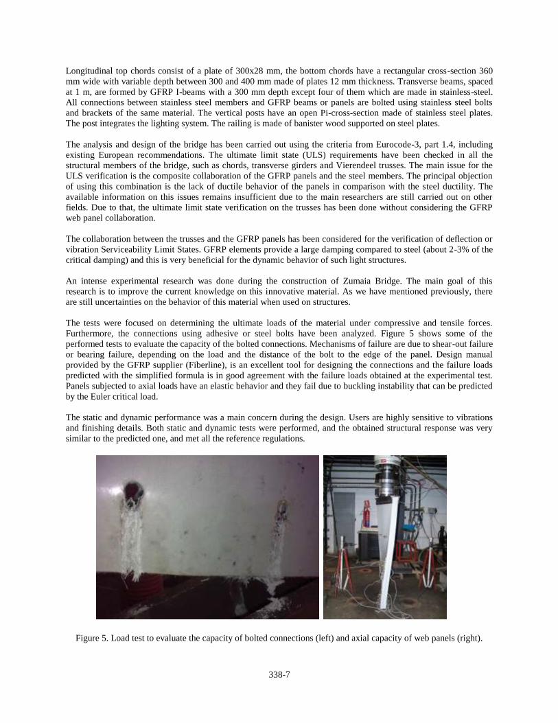

Introduction
The use of fibre-reinforced plastic pro-files in civil engineering structures has undergone a significant developmentover the last decade From the con-struction of the cable-stayed footbridgeat Aberfeldy UK (1992) to that of the Pontresina footbridge Switzerland(1997) some ten further bridges par-tially or entirely using composite ma-terials [1 2 and 3] have been reportedin technical literature Most of theserecent structures are truss-type bridgesusing glass-fibre-reinforced plastic(GFRP) pultruded profiles
The footbridge presented in this paperis located about 2 km from the city ofLleida in Spain and was built to crossa roadway a railway line and the newprojected high-speed railway line be-tween Madrid and Barcelona Theowners required a new pedestrianstructure with minimum maintenanceand which would be easy to erect Thefootbridge was completed in October2001
The proposed and accepted construc-tion solution resulted in an innovativedesign using GFRP pultruded profileswhich have no magnetic interactionwith the electrified railway line mini-mum maintenance costs and was easyto build (Fig 1) Thanks to its light-
ness it took only 3 hours to completethe erection of the bridge to its finalposition The principle factor contri-buting to the construction of this bridgewas the creative spirit of all those in-volved in this project
General description
A main problem was that of finding anappropriate structural form to spanthe required 38 m length using stan-dard GFRP profiles The final struc-ture is a double-tied arch of 38 m span-length with a rise of 62 m (spanrise 6)and 3 m wide (Fig 2) The arch config-uration was chosen to minimize service-ability problems due to the low modu-lus of elasticity of GFRP profiles The
arches are inclined 6deg to achieve amore pleasant appearance (Fig 3)The total weight of the bridge is approx-imately 19 t It is possible that it is thelongest span bridge in the world usingthis type of structure
All of the profiles are made of fibre-reinforced plastics using continuous E-glass fibres combined with wovenand complex mats with a minimumglass-fibre content of 50 The matrixis made of isophthalic polyester Themodulus of elasticity in the longitudi-nal direction ranges from 23ndash27 GPadepending on the type of profile Itstensile or compressive strength in thelongitudinal direction is 240 MPa andits strength in the transverse directionvaries from 50 to 70 MPa
Both arches and the tied longitudinalmembers present a rectangular hollowcross-section made up of two U 300 times90 times 15 mm profiles joined with gluedflat plates of 180 times 12 mm to form abeam tube (Fig 4) The supplier of theprofiles carried out full-scale testing
84 Advanced Materials Structural Engineering International 22002
Towards Advanced Composite Material FootbridgesJuan A Sobrino Dr Mordf Dolores G Pulido Civil Eng Pedelta Barcelona Spain
Fig 1 General view of the entire GFRP footbridge
Fig 2 Elevation and plan views of the footbridgeFig 3 Elevation and view of the footbridgefrom the west ramp
to verify the beam joints using the proposed epoxy adhesive In order toreduce horizontal deformation of thearches due to wind pressure these ele-ments are forked out into two branch-es using the same profiled sections(Fig 3)
The hangers are I-profiles of 160 times80 times 8 mm The arches are connectedby square tubes of 100 mm size and areof various thickness (6 to 8 mm)
The deck is made up of transverse I-beams of 200 times 100 times 10 mm spacedat 06 m and directly supporting the 4 cm thick deck panels which form thetransit or roadway surface A bracingsystem to avoid distortion was designedusing diagonal U-section members of160 times 48 times 8 mm as a typical cross-sec-tion (Fig 5)
The chief problem with GFRP struc-tures is the design construction and assembly of the joints due to the aniso-tropic behaviour of the FRP profilesAs a result of the lack of experience
with glued connections on bridges alljoints are bolted using stainless steelbrackets and bolts (Fig 6 and 7) Diag-onal elements were added in the de-sign joining the nodes of the archesand the tied longitudinal members toimprove the dynamic behaviour of thebridge To reduce its visual imagestainless steel cable elements of 12 mmin diameter were selected
Access to the arch bridge was createdusing reinforced concrete ramps con-ceived as a continuous beam of 10 mmaximum span-length and 06 m indepth The slope of the ramps is limit-ed to 8 to guarantee complete acces-sibility for disabled persons
Design criteria
Structural static and dynamic analyseswere carried out using a three-dimen-sional bar model and assuming elasticbehaviour
The design had to comply with the Serviceability Limit States required by the Spanish Bridge Design Code Thebridge has been designed for a nomi-nal uniform load of 4 kNm2 The par-tial safety factors for material proper-ties adopted to verify the UltimateLimit States were 2 for normal stress-es and 3 for shear stresses For buck-ling stability verification the meanmodulus of elasticity was reduced by afactor of 2 The design of most of theelements was governed by the LimitState of Deformation and in some ofthe elements of the arches by bucklingstability
Deflection under frequent loads (2kNm2) is about 24 mm (L1580) Staticand dynamic tests were performed be-fore the erection of the bridge in its final position During the static tests ndashusing 16 t water containers each equi-valent to 2 kNm2 mean load ndash the max-imum deflection reached was 26 mmResidual deflection was 7 mm and was
probably due to the adjustment of thebolts and connections The structuralbehaviour was practically linear (Fig 8and 9)
Special attention was given to the dy-namic behaviour First frequency (flex-ural mode) obtained in the analysiswas 269 Hz Maximum accelerationwas limited by introducing diagonal el-ements joining arches and longitudinaltied elements to obtain a stiffer struc-ture The first frequency measuredduring the dynamic test was 275 Hzand viscous damping was 25 to 3of critical damping
The parameters measured during thetest show that the structure is consider-ably stiffer than indicated by theoreti-cal predictions This is due to the pro-filed members having a higher defor-mation modulus than was presumed inthe design stage and also to the extrastiffness of the connections (which insome cases were rejected in the designstage)
To avoid fractures in the rectangulartubes of the arches and the tied longi-tudinal beams some of the joints werefilled with a mortar of sand and resinIn the diagonal elements PVC blockswere used for the same purpose Dueto the complex geometry in some cas-es it was impossible to fill them with ei-ther mortar or PVC blocks It shouldbe noted that the higher temperaturesinduced by the use of considerable vol-umes of resin mortar may end up dam-aging the profiles Detailed analyses ofjoints without mortar were carried outusing finite element models includingsteel brackets The purpose was toquantify the stresses and deformationsproduced by the pressure induced bythe bolts
Construction
The structural elements were manu-factured in Denmark and transported
Structural Engineering International 22002 Advanced Materials 85
Fig 4 Arch profiles Fig 6 Connections between floor profiles Fig 7 Connections in the arch
Fig 5 Floor system
to Spain for assembly The maximumlength of the elements transported is 9 m The bridge construction processwas as follows
ndash construction of the reinforced con-crete end-ramps
ndash construction of temporary columnsnext to the ramps so as to permitmounting the complete FRP structure
ndash the assembly of the deckrsquos members ndash assembly of the vertical elements
and archesndash the painting of the FRP profiles (in
white and blue)ndash the partial demolition of the tempo-
rary columns so as to transfer theloads to the end piers reproducing thefinal support configuration to permitperforming static and dynamic tests
ndash the installation of the structure span-ning a busy railway line within a 3hour time-limit (Fig 10)
The assembly was carried out by 8 peo-ple working over 3 months The lowweight of the bridge coupled with thepossibility of using simple hand toolsfor machining the required adjustmentsmade the bridge assembly much easi-er Some difficulties arose during theerection of the arches due to theircomplex geometry requiring minimumtolerances in the length of the profilesand the geometry of the steel bracketsThis resulted in some adjustments on site
Conclusions
The positive interaction between theadministration the contractor the sub-contractors and the design engineerswas the principle factor in making thisinnovative footbridge a reality
The range of application of advancedfibre-composite materials is very wideparticularly when minimum mainte-nance lightness transportation facili-ties no magnetic interaction or quickerection times are required The initialcost due to material supply and designis higher when compared with tradi-tional steel-based solutions howeverconsiderable savings are made in con-struction and maintenance
The development and future of advanc-ed composite materials for architectur-al and civil engineering structural ap-plications will depend basically on thedevelopment of new structural formsand element-joining techniques Struc-tural codes could help to spread theuse of full advanced composite plasticstructures but regulations of thesestandard documents could also have anegative effect on the creativity ofstructural engineers
Engineers possess a magnificent po-tential knowledge regarding the be-haviour of materials and structures butaesthetics should also be taken into account as well as structural perfor-mance and economy All this couldeasily be done by simply making an ex-tra effort during the conceptual designstage This footbridge demonstratesthat advanced composite materials canbe easily introduced into most types ofstructural forms thus taking advantageof their outstanding mechanical andchemical properties
References
[1] KELLER T Towards Structural Forms forComposite Fibre Materials Structural Engineer-ing International IABSE Zurich Vol 9 No 41999 pp 297ndash300
[2] BURGOYNE CJ Advanced Composites inCivil Engineering in Europe Structural Engineer-ing International IABSE Zurich Vol 9 No 41999 pp 267ndash273
[3] BRAESTRUP MW Footbridge Constructedfrom Glass-fibre-reinforced Profiles DenmarkStructural Engineering International IABSEZurich Vol 9 No 4 1999 pp 256ndash258
86 Advanced Materials Structural Engineering International 22002
App
lied
test
load
(kp
m2 )
250
200
150
100
50
00 5 10 15 20 25 30
Deflection at mid-span (mm)
Fig 8 Mid-span deflection measured dur-ing static test
Fig 9 General view of the load static testmade before the final erection of the bridge
Fig 10 Erection of the bridge
SEI Data Block
OwnerGestor de Infraestructuras Ferroviarias
Structural designJuan A Sobrino Javier Jordaacuten and Mordf Dolores G Pulido civil engineersPEDELTA
ContractorUTE Lleida RUBAU Construccions ndashCOPASA Spain
SubcontractorFiberline Denmark
Total cost (USD) 325 000 USD
Cost of composite structure (USD) 270 000 USD (2350 USDm2)
Service date October 2001
96 Reports Structural Engineering International 22006
Summary
One of the most interesting things in the development of bridge engineering is the exploration of new structural materials like for example stainless steel with its excellent mechanical properties magnificent durability and aesthetic possibilities The use of new structural materials in bridge engineering constitutes a metaphor to the innovation and at the same time a vindication of the enormous value of en-gineering as an impelling element of the development and progress of the society building bridges for the future and paving the way to the ones that follow
This paper describes a composite stainless steel road bridge recently built in Cala Galdana (Menorca) being the first road bridge in Europe and probably world-wide using stainless steel for the structure
its high resistance to corrosion from the marine atmosphere as the solution that better responded to the ownerrsquos requirements The new bridge has be-come a landmark for the island thanks to the technological innovation of using stainless steel
The solution has been designed fulfillingfour explicit objectives environmentalrespect (during construction and in serv-ice recovery of the old river bed) high durability minimum maintenance and a symbol of advanced technology (Fig 1)
Stainless Steel as Structural Material Though the variety of the stainless steels is enormous it is possible to find more than 100 types of frequently used grades They contain as a common denominator at least 11 of chromium that with the presence of other compo-nents as nickel molybdenum or nitro-gen among others gives a steel alloy that exhibits a great corrosion resistance ductility and mechanical strength even when exposed to high temperatures as well as excellent aesthetic possibilities and easy maintenance and cleaning The chromium contained in the stainless steel forms a soft stable and transpar-ent layer of chromium oxide (Cr2O3) on the surface (passivation layer) that avoids corrosion
Four types of stainless steel exist accord-ing to their metallurgical structure fer-ritic austenitic duplex and martensitic Duplex stainless steel is an austen-itic-ferritic alloy with a microstruc ture of great corrosion resistance excellent
Stainless Steel Road Bridge in Menorca Spain Juan A Sobrino Dr Eng PEDELTA Barcelona Spain
Fig 1 General view of the bridge over Algendar river
Introduction
The island of Menorca was declared a unique biosphere by UNESCO thanks to the natural surroundings and its rich historical and ethnological heritage an outdoor museum Cala Galdana is with its shell form 450 m long and 45 m wide one of the most beautiful beaches of the island The surround-ings are only partially urbanized and they contribute to the attractiveness of the island to tourists
Algendar river terminates at the beach of Cala Galdana and it has been crossed for the last 30 years via a rein-forced concrete bridge approximately 18 m long Due to its advanced state of corrosion induced by the marine atmosphere and an important support settlement in one of the abutments the owner decided to substitute it by a new bridge The new bridge should span the entire width of the old river more than 40 m fitting harmoniously in the natural surroundings and making use of a material with great durability and minimum maintenance
During the design process different structural and material alternatives were analysed Eventually a duplex stainlesssteel arch structure was chosen due to
Report X-110indd 96Report X-110indd 96 42106 15654 PM42106 15654 PM
Structural Engineering International 22006 Reports 97
duc tility and mechanical characteristics superior to the great majority of carbon steels Thanks to their high strength duplex steels are suitable for applica-tion in bridges and footbridges [1] [2] With the existence of a wide range of duplex steel grades the selection of the most suitable type clearly depends on the ambient aggressiveness type of cor-rosion mechanical properties types of surface finish and so forth
Stainless steel unlike the conventional carbon steels presents a mechanical nonlinear behaviour even under re-duced stress values without having an elastic limit strength clearly defined However the stress value associated to a strain of 02 has been adopted as a conventional yield stress (f02) For hot rolled plate and taking as an example the duplex steel 14462 used in the bridge of Cala Galdana (Menorca) de-scribed in this article mechanical prop-erties of the material are summarized in Table 1 comparing it with the stain-less steel 14404 (ASTM 316 L) and the carbon steel S-355
Surprisingly in spite of the impact that stainless steel has had in industry naval construction architecture or consumer products for more than 50 years its presence in civil engineering and in particular in structures has been virtu-ally nonexistent until just a few years ago Nevertheless there have already been built some very interesting foot-bridges [2]
Bridge Description
The overall length of the bridge is 55 m with a 13 m wide deck The deck allocates 2 lanes of road traffic (7 m) and two lateral sidewalks each 2 m wide that allow the pedestrians to enjoy the panoramic views from an excellent location
The main structure consists of two par-allel arches with an intermediate deck The arches and the deck join at the
abutments by means of an inclined strut that takes the horizontal component of the arch axial force and consequently significant horizontal forces are not transferred to the abutments
Substructure
The soil conditions for foundations of the two abutments are very differ-ent Whereas in abutment 1 on the right riverside the resistant substra-tum (Miocene limestone) is at a depth of more than 40 m in the opposite abutment the limestone appears at a depth of only about 4 m
Abutment 1 is a big reinforced concrete block with a footprint of 114 95 m2 and 38 m high supported on 14 prefab-ricated concrete piles of 04 04 m2 and 42 m long As an aesthetic feature the visible surfaces have been inclined to integrate them into the embankment and horizontal shallow channels have been spaced at 15 cm intervals to avoid large smooth surfaces Abutment 2 is directly founded on surface limestone Its dimensions are greater than those of Abutment 1 with a footprint of 115 13 m2 and 72 m high
Each abutment supports the bases of the parallel arches and the two longi-tudinal beams of the deck The arches are supported on POT bearings and the beams on laminated elastomeric bearings In order to avoid the vertical displacement of the deck with respect to the abutment four vertical anchor-ages (constituted by four unbonded post-tensioned cables with 12 strands of 15 mm) were applied The inclined struts that connect the base of the arch and the end of the deck have been re-cessed into the front face of the abut-ment (Fig 2)
Structure
The structural scheme is constituted by two parallel arches with a free span of 45 m and an intermediate deck The
Fig 2 Abutment 2 view of the completed element
2 2 2 2
100
210 100 100 210700
1320
700 100
Fig 3 Typical deck cross-section
Fig 4 View of bridge from below
Mechanical property Stainless steel Stainless steel 14404 Carbon steel S-355 Stainless steel Duplex 14462 (ASTM-316L) Duplex 14462 (Minimum specified (used in Cala values) Galdana Bridge)
Tensile strength (MPa) 640 530 510 767
Conventional yield stress f02 (MPa) 460 220 355 535
Elongation () 25 40 gt15 35
Table 1 Mechanical properties at 20deg C Minimum specified values of three different steels
main structure is made of duplex stain-less steel grade 14462 which exhibits a high resistance to corrosion by chlo-rides The deck is made of reinforced concrete connected to a series of trans-verse beams (Fig 3)
The arches rise to a total of 6 m (rela-tion spanrise 75) and they are tied to the deck by means of two connected longitudinal beams These longitudinal beams are again connected by means of transverse beams (Fig 4)
Report X-110indd 97Report X-110indd 97 42106 15703 PM42106 15703 PM
98 Reports Structural Engineering International 22006
The arches have a triangular cross-section (Fig 5) with a central web Their depth is 070 m - constant throughout their overall length However the width of the section varies between 070 and 1 m The central web of the section is transformed into a cellular plate that allows connecting the arch with the longitudinal deck beam The longitudi-nal beams are rectangular hollow sec-tions of 1 m 05 m constituted by plates with varying thicknesses between 15 and 25 mm In the central zone with the arch above the deck these beams have a central web that is connected to the web of the arch allowing direct transfer of the vertical loads of the lon-gitudinal beam to the arch
The transverse beams spaced at 2 m are formed by rectangular cross-sections 025 m wide and with a variable depth varying between 050 and 057 m (to obtain) the deck cross-slope of 2 constituted by plates of 10 and 12 mm These beams are structurally connected to the reinforced concrete slab hav-ing an average thickness of 030 m by means of Bernold type studs of 20 mm in diameter
In order not to transfer the horizontal component of the arch axial force to the abutments two inclined strutsndashconnecting the base of the arch and the end of the longitudinal beam have been designed which are anchored at the top of the abutments The struts have a rectangular hollow cross-sectionwith outer dimensions of 1 m 05 m formed by plates of 20 and 25 mm thickness internally stiffened in both longitudinal and transverse directions
One of the most difficult connections is the one between the inclined strut (of rectangular cross-section) and the
base of the arch (of triangular cross-section) This element is directly sup-ported by the pot bearing (Fig 6) and is strongly stiffened
The lateral sidewalks are separated from the road by the arches (Fig 4) These sidewalks are supported by means of a reinforced concrete slab supported on transverse cantilever ribs every 2 m con-nected to the longitudinal beam
The railing has been designed with wood en banisters with an elliptical
cross-section supported by posts of curved geometry made of stainless steel every 2 m joined to the end of the trans-verse ribs as if it was only one piece
Structural Behaviour
The analysis and design of the bridge has been carried out using the criteria from Eurocode 3 part 14 [3] including consultation of bibliography and exist-ing recommendations from European associations [4] [5]
VARIABLE 7001000
50deg
58deg
25
20
25
15
1515
15
470
500
1000
25
20
ARCH
LONGITUDINAL BEAM
Fig 5 Typical cross-section of the arch and longitudinal beam
30 3025
40
40
40
462 30477
462477
955
25
2525
455
455
40
40
40
40
25
2513
813
812
912
913
813
825
2525
2525
1000
500
40
40
40
25
25
336
336 358
25 2530
40
1000
40
580
40
67725
40
40
40
698
50˚
Fig 6 Joint between strut and arch
Report X-110indd 98Report X-110indd 98 42106 15718 PM42106 15718 PM
Structural Engineering International 22006 Reports 99
The structural behaviour of the bridge is a self-anchored arch that does not transfer horizontal reaction forces to the foundations In Fig 7 the reactions as well as the transfer of axial internal forces among the main elements have been illustrated
The structural calculations have been made with a standard finite element programme developing diverse mod-els or adjustments to contemplate the phenomena of softening of the stainless steel under stresses over 60 of the conventional elastic limit(02 proof stress f02) and the crack-ing effects in certain zones of the re-inforced concrete slab The general model combines bar type and shell elements
The steel stresses have been limited to 75 of f02 for the combination of fre-quent loads and to 90 of f02 for the characteristic combination
Construction Process
The works of the bridge began in Octo-ber 2004 starting with the demolition of the existing bridge and were completed the first week of June 2005
Processes of construction with stain-less steel are similar to those used for carbon steels but non identical adopting specific techniques for cut-ting bending forming welding and finishing Welding consumables must also be specific to the stainless steel grade to guarantee equal mechanical and corrosion properties to those of the base material
Welding techniques used were with shielded metal arc welding (SMAW) using an inert gas with covered elec-trode metal inert gas (MIG) flux cored arc welding (FCAW) and submerged arc welding (SAW) [6] without preheat-ing and not exceeding a temperature of 150deg C between two consecutive passes Welding produces an oxidation of the base metal and a significant change of surface colour and the appearance tex-ture that should be corrected by means of a later treatment This aspect is essential
to guarantee the desired surface fin-ish colour and texture After removing solid slag in the weld a chemical treat-ment (pickling) has been applied by means of a pickling paste constituted by acids hydrofluoric and nitric Its application during 4 hours allows the removing of contaminants and oxides generated during welding and facili-tate the formation of the passive layer Finally in order to guarantee a uniform finished surface of the pieces a blasting treatment with high pressure using glass micro-spheres has been applied
The contact of the stainless steel with other metals during the manufacturing or in its definitive location can cause galvanic corrosion For this reason man-ufacturing and assembly of the structur-al parts was carried out in zones where it does not come in contact with car-bon steel
The bridge was assembled on site by means of crane placing 8 sections on temporary supports for later welding (Fig 8)
Once the construction of the bridge was completed a static load test was carried out considering different load stages
and measuring essentially verticaldeflections The structure presents a stiffer behaviour than expected The measured deflections were about 80 of the theoretical values obtained with an average value of the modulus of elasticity of E = 200 GPa The de-flections recovered elastically practi-cally in their totality Considering the results of the quality control of the steel which affirms that the secant modulus of elasticity at 02 is 16 superior to the one considered in the calculation model explains the difference of deflec-tions measured in the test of load
An exhaustive quality control process has been undertaken increased by the innovative character of the material having intensified all the internal con-trols of the welds both off and on site with techniques such as ultrasonic test-ing X-rays and magnetic particles The measured values of the stainless steel mechanical properties at the quality control turned out to be greater than the ones specified in the design and the Codes (Table 1)
Conclusion
The fundamental advances in struc-tural engineering have always been related to the use of new materials The increase in the use of advanced materials in bridge design can partially be attributed to the increasing aware-ness from Public Administrations to use materials that require reducedmaintenance in addition to having
Fig 8 Assembly of the steel structure
minus6760 kN
minus10160 kN minus11140 kN
minus4370 kN5070 kN
8130 kN
4450 kN
Fig 7 Distribution of reactions and axial forces (kN) in the most unfavourable service combination
Report X-110indd 99Report X-110indd 99 42106 15719 PM42106 15719 PM
100 Reports Structural Engineering International 22006
greater mechanical resistance This opens up an attractive way for bridge engineering
Cala Galdana Bridge a landmark of Menorca illustrates the great possibili-ties offered by stainless steel to struc-tural engineering Even if the cost of the stainless steel is sensibly superior to that of conventional materials (car-bon steel and concrete) an economical decision based on life cycle cost of the structure enhances structural solutions with stainless steel thanks to the con-siderable economical saving from its reduced maintenance
Acknowledgements
The positive interaction between the client contractor subcontractors and the consulting engineers has made this innovating project a reality Spe-cial thanks to the Consell Insular de
Menorca for its support and promo-tion of the application of innovative technologies to bridge engineering
References
[1] PASCUAL J RIPA T Y MILLANES F ldquoSome singularities of stainless steel as structural materialrdquo (in Spanish) CEA 2004 Structural Steel Congress pp 229ndash238 La Coruna (Spain) 2004
[2] Eurinox ldquoPedestrian bridges in stainless steelrdquo building series volume 7 Luxembourg 2004
[3] ENV 1993-14 ldquoEurocode 3 Design of steel structures Supplementary rules for stainless steelrdquo
[4] Eurinox ldquoDesign manual for structural stain-less steel (2nd edition)rdquo building series volume 3 Luxembourg 2002
[5] The Steel Construction Institute ldquoStructural design of stainless steelrdquo SCI Publication P291 Ascot UK 2001
[6] American Welding Society ldquoWelding Hand-bookrdquo Volumes 1 and 2 Miami FL 2004
SEI Data Block
Owner Consell Insular de Menorca Mobility Directorate
Design and Technical Assistance During ConstructionPEDELTA Juan A Sobrino Juan V Tirado Javier Jordan Xavier Martinez (Civil Engineers) and Agusti Garcia (Industrial Engineer)
ContractorFERROVIAL
SubcontractorsOUTOKUMPU supply and prepara-tion of plates ASCAMON steel fabricator (main subcontractor) MEKANO-4 stainless steel bearings
Stainless Steel (t) 165 (225 Kgm2)
Total Cost of the Bridge (EUR millions) 26 (including accesses)
Service Date June 2005
Fiberline Composites ASNr Bjertvej 88DK 6000 KoldingTel +45 70 13 77 13Fax +45 70 13 77 14fiberlinefiberlinecomwwwfiberlinecomldquoFootbridge Award 2005rdquo
The journal Bridge design amp engineering
Installed in just three hoursThe award-winning GRP footbridge near Lleida Spain was custom-built to demanding specifications of the Spanish railway authorities for minimal maintenance fast installation and zero magnetic interference
As the bridge would cross a major rail link minimising disruption to services was a key priority Accordingly the bridge was assembled at the track side and then craned into place resulting in a railway possession time of only three hours for the complete erection
The bridge was designed by the Spanish engineering consultant Pedelta and built using structural components supplied by Fiberline Composites
Report X-110indd 100Report X-110indd 100 42106 15727 PM42106 15727 PM
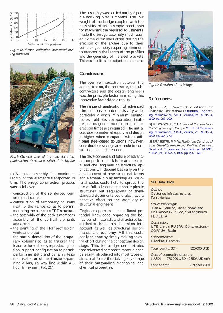