bridgeport cnc dx32 programmer’s manual · pdf filebridgeport cnc dx32...
TRANSCRIPT

BRIDGEPORT CNC
DX32
Programmer’s Manual
February 1994
Code No. 11042638Rev. A
@@@@@@@@@@@@@@@@@@@@@@@@@@@@@@@@@@@@@@@@@@@@@@@@@@@@@@@@@@@@@@@@@@@@@@@@@@@@@@@@@@@@@@@@@@@@@@@@@@@@@@@@@@@@@@@@@@@@@@@@@@@@@@@@@@@@@@@@@@@@@@@@@@@@@@@@@@@@@@@@@@@@@@@@@@@@@@@@@@@@@@@@@@@@@@@@@@@@@@@@@@@@@@@@@@@@@@@@@@@@@@@@@@@@@@@@@@@@@@@@@@@@@@@@@@@@@@@@@@@@@@@@@@@@@@@@@@@@@@@@@@@@@@@@@@@@@@@@@@@@@@@@@@@@@@@@@@@@@@@@@@@@@@@@@@@@@@@@@@@@@@@@@@@@@@@@@@@@@@@@@@@@@@@@@@@@@@@@@@@@@@@@@@@@@@@@@@@@@@@@@@@@@@@@@@@@@@e@@@@@@@@@@@@@@@@@@@@@@@@@@@@@@@@@@@@@@@@@@@@@@@@@@@@@@@@@@@@@@@@@@@@@@@@@@@@@@@@@@@@@@@@@@@@@@@@@@@@@@@@@@@@@@@@@@@@@@@@@@@@@@@@@@@@@@@@@@@@@@@@@@@@@@@@@@@@@@@@@@@@@@@@@@@@@@@@@@@@@@@@@@@@@@@@@@@@@@@@@@@@@@@@@@@@@@@@@@@@@@@@@@@@@@@@@@@@@@@@@@@@@@@@@@@@@@@@@@@@@@@@@@@@@@@@@@@@@@@@@@@@@@@@@@@@@@@@@@@@@@@@@@@@@@@@@@@@@@@@@@@@@@@@@@@@@@@@@@@@@@@@@@@@@@@@@@@@@@@@@@@@@@@@@@@@@@@@@@@@@@@@@@@@@@@@@@@@@@@@@@@@@@@@@@@@@@e@@@@@@@@@@@@@@@@@@@@@@@@@@@@@@@@@@@@@@@@@@@@@@@@@@@@@@@@@@@@@@@@@@@@@@@@@@@@@@@@@@@@@@@@@@@@@@@@@@@@@@@@@@@@@@@@@@@@@@@@@@@@@@@@@@@@@@@@@@@@@@@@@@@@@@@@@@@@@@@@@@@@@@@@@@@@@@@@@@@@@@@@@@@@@@@@@@@@@@@@@@@@@@@@@@@@@@@@@@@@@@@@@@@@@@@@@@@@@@@@@@@@@@@@@@@@@@@@@@@@@@@@@@@@@@@@@@@@@@@@@@@@@@@@@@@@@@@@@@@@@@@@@@@@@@@@@@@@@@@@@@@@@@@@@@@@@@@@@@@@@@@@@@@@@@@@@@@@@@@@@@@@@@@@@@@@@@@@@@@@@@@@@@@@@@@@@@@@@@@@@@@@@@@@@@@@@@e@@@@@@@@@@@@@@@@@@@@@@@@@@@@@@@@@@@@@@@@@@@@@@@@@@@@@@@@@@@@@@@@@@@@@@@@@@@@@@@@@@@@@@@@@@@@@@@@@@@@@@@@@@@@@@@@@@@@@@@@@@@@@@@@@@@@@@@@@@@@@@@@@@@@@@@@@@@@@@@@@@@@@@@@@@@@@@@@@@@@@@@@@@@@@@@@@@@@@@@@@@@@@@@@@@@@@@@@@@@@@@@@@@@@@@@@@@@@@@@@@@@@@@@@@@@@@@@@@@@@@@@@@@@@@@@@@@@@@@@@@@@@@@@@@@@@@@@@@@@@@@@@@@@@@@@@@@@@@@@@@@@@@@@@@@@@@@@@@@@@@@@@@@@@@@@@@@@@@@@@@@@@@@@@@@@@@@@@@@@@@@@@@@@@@@@@@@@@@@@@@@@@@@@@@@@@@@e@@@@@@@@@@@@@@@@@@@@@@@@@@@@@@@@@@@@@@@@@@@@@@@@@@@@@@@@@@@@@@@@@@@@@@@@@@@@@@@@@@@@@@@@@@@@@@@@@@@@@@@@@@@@@@@@@@@@@@@@@@@@@@@@@@@@@@@@@@@@@@@@@@@@@@@@@@@@@@@@@@@@@@@@@@@@@@@@@@@@@@@@@@@@@@@@@@@@@@@@@@@@@@@@@@@@@@@@@@@@@@@@@@@@@@@@@@@@@@@@@@@@@@@@@@@@@@@@@@@@@@@@@@@@@@@@@@@@@@@@@@@@@@@@@@@@@@@@@@@@@@@@@@@@@@@@@@@@@@@@@@@@@@@@@@@@@@@@@@@@@@@@@@@@@@@@@@@@@@@@@@@@@@@@@@@@@@@@@@@@@@@@@@@@@@@@@@@@@@@@@@@@@@@@@@@@@@e@@@@@@@@@@@@@@@@@@@@@@@@@@@@@@@@@@@@@@@@@@@@@@@@@@@@@@@@@@@@@@@@@@@@@@@@@@@@@@@@@@@@@@@@@@@@@@@@@@@@@@@@@@@@@@@@@@@@@@@@@@@@@@@@@@@@@@@@@@@@@@@@@@@@@@@@@@@@@@@@@@@@@@@@@@@@@@@@@@@@@@@@@@@@@@@@@@@@@@@@@@@@@@@@@@@@@@@@@@@@@@@@@@@@@@@@@@@@@@@@@@@@@@@@@@@@@@@@@@@@@@@@@@@@@@@@@@@@@@@@@@@@@@@@@@@@@@@@@@@@@@@@@@@@@@@@@@@@@@@@@@@@@@@@@@@@@@@@@@@@@@@@@@@@@@@@@@@@@@@@@@@@@@@@@@@@@@@@@@@@@@@@@@@@@@@@@@@@@@@@@@@@@@@@@@@@@@e@@@@@@@@@@@@@@@@@@@@@@@@@@@@@@@@@@@@@@@@@@@@@@@@@@@@@@@@@@@@@@@@@@@@@@@@@@@@@@@@@@@@@@@@@@@@@@@@@@@@@@@@@@@@@@@@@@@@@@@@@@@@@@@@@@@@@@@@@@@@@@@@@@@@@@@@@@@@@@@@@@@@@@@@@@@@@@@@@@@@@@@@@@@@@@@@@@@@@@@@@@@@@@@@@@@@@@@@@@@@@@@@@@@@@@@@@@@@@@@@@@@@@@@@@@@@@@@@@@@@@@@@@@@@@@@@@@@@@@@@@@@@@@@@@@@@@@@@@@@@@@@@@@@@@@@@@@@@@@@@@@@@@@@@@@@@@@@@@@@@@@@@@@@@@@@@@@@@@@@@@@@@@@@@@@@@@@@@@@@@@@@@@@@@@@@@@@@@@@@@@@@@@@@@@@@@@@e@@@@@@@@@@@@@@@@@@@@@@@@@@@@@@@@@@@@@@@@@@@@@@@@@@@@@@@@@@@@@@@@@@@@@@@@@@@@@@@@@@@@@@@@@@@@@@@@@@@@@@@@@@@@@@@@@@@@@@@@@@@@@@@@@@@@@@@@@@@@@@@@@@@@@@@@@@@@@@@@@@@@@@@@@@@@@@@@@@@@@@@@@@@@@@@@@@@@@@@@@@@@@@@@@@@@@@@@@@@@@@@@@@@@@@@@@@@@@@@@@@@@@@@@@@@@@@@@@@@@@@@@@@@@@@@@@@@@@@@@@@@@@@@@@@@@@@@@@@@@@@@@@@@@@@@@@@@@@@@@@@@@@@@@@@@@@@@@@@@@@@@@@@@@@@@@@@@@@@@@@@@@@@@@@@@@@@@@@@@@@@@@@@@@@@@@@@@@@@@@@@@@@@@@@@@@@@e
@@@@@@@@@@@@@@@@@@@@@@@@@@@@@@@@@@@@@@@@@@@@@@@@@@@@@@@@@@@@@@@@@@@@@@@@@@@@@@@@@@@@@@@@@@@@@@@@@@@@@@@@@@@@@@@@@@@@@@@@@@@@@@@@@@@@@@@@@@@@@@@@@@@@@@@@@@@@@@@@@@@@@@@@@@@@@@@@@@@@@@@@@@@@@@@@@@@@@@@@@@@@@@@@@@@@@@@@@@@@@@@@@@@@@@@@@@@@@@@@@@@@@@@@@@@@@@@@@@@@@@@@@@@@@@@@@@@@@@@@@@@@@@@@@@@@@@@@@@@@@@@@@@@@@@@@@@@@@@@@@@@@@@@@@@@@@@@@@@@@@@@@@@@@@@@@@@@@@@@@@@@@@@@@@@@@@@@@@@@@@@@@@@@@@@@@@@@@@@@@@@@@@@@@@@@@@@e
@@@@@@@@@@@@@@@@@@@@@@@@@@@@@@@@@@@@@@@@@@@@@@@@@@@@@@@@@@@@@@@@@@@@@@@@@@@@@@@@@@@@@@@@@@@@@@@@@@@@@@@@@@@@@@@@@@@@@@@@@@@@@@@@@@@@@@@@@@@@@@@@@@@@@@@@@@@@@@@@@@@@@@@@@@@@@@@@@@@@@@@@@@@@@@@@@@@@@@@@@@@@@@@@@@@@@@@@@@@@@@@@@@@@@@@@@@@@@@@@@@@@@@@@@@@@@@@@@@@@@@@@@@@@@@@@@@@@@@@@@@@@@@@@@@@@@@@@@@@@@@@@@@@@@@@@@@@@@@@@@@@@@@@@@@@@@@@@@@@@@@@@@@@@@@@@@@@@@@@@@@@@@@@@@@@@@@@@@@@@@@@@@@@@@@@@@@@@@@@@@@@@@@@@@@@@@@e
®

COPYRIGHT 1994 BRIDGEPORT MACHINES, INC., ALLRIGHTS RESERVED
This manual describes software that contains published and unpublished works of authorshipproprietary to Bridgeport Machines, Inc. It is made available for use and maintenance of our products.Under copyright laws, this manual, or the software it describes may not be copied in whole, or in part,without prior written consent of Bridgeport Machines, Inc., except in normal software use, asdescribed in the software license agreement.
The information in this document is subject to change without notice and should not be construed as acommitment by Bridgeport Machines, Inc.
ii

TABLE OF CONTENTS
Chapter 1 INTRODUCTION 1PURPOSE AND SCOPE 1OVERALL DESCRIPTION 1COMPATABILITY WITH BOSS 8 & 9 PROGRAMS 1COM PATABI LITY WITH BOSS 4-7 PROGRAMS 1
Chapter 2 PROGRAMMING FORMAT 3OVERVIEW 3PART PROGRAM STRUCTURE 3
Blocks 3Words 3
SPECIAL FEATURES 6Program Number 6Definition Blocks 6Block Delete 6
THE COMPOSITION OF THE BLOCK 6Sequence Number 7Preparatory Functions (G-Codes) 7Coordinate Words 7Feedrate 7Auxiliary Machine Control Functions 7
Chapter 3 PREPARATORY FUNCTIONS 9OVERVIEW 9GO — RAPID TRAVERSE POSITIONING 10G1 — LINEAR INTERPOLATION 11G2, G3 — CIRCULAR INTERPOLATION 12
Circular Programming 13Circular Interpolation by Radius Programming 14
G4— DWELL 16G8, G9 — MODAL DECELERATION OVERRIDE 17G12, G13 — HELICAL INTERPOLATION 17
Sprial Interpolation 18G17, G18, G19 — PLANE SWITCHING 18G22, G23 — FILLET PROGRAMMING 18G30, G31, G32 — MIRROR IMAGE 19G40, G41, G42 — CUTTER DIA. COMPENSATION 19G44, G45 — CONSTANT SURFACE FEED 19G48, G49 — CORNER ROUNDING IN CUTTER COMP 20G70, G71 — INCH/METRIC CONVERSION 20G72, G73 — TRANSFORMATION FUNCTION 20G74, G75 — ARC CENTER IN CIRCULAR PROGR 20G77, G78, G79 — MILLING CYCLES 20G80-G87, G89 — DRILLING CYCLES 21G90, G91 — ABSOLUTE/INCREMENTAL PROGR 21G92 — PROGRAMMING OF ABSOLUTE ZERO POINT 21G96, G97 — FIXTURE OFFSETS 21G99 — DECELERATION OVERRIDE 22G170-G177, G179 — MILL CYCLES 22G181-G187, G189 — DRILL PATTERNS — ROWS 22
iii

G191-G197, G199 — DRILL PATTERNS — FRAME 22
Chapter 4 COORDINATE WORDS 22OVERVIEW 23CONTROLLED AXIS 23COORDINATE SYSTEMS 23
Machine Coordinate System 23Part Program Coordinate System 23Software Limits 25
TOOL LENGTH OFFSET 27ABSOLUTE AND INCREMENTAL PROGRAMMING 27POLAR COORDINATES 28SPHERICAL COORDINATES 29TRANSFORMATIONS 30
Rotation 30Scaling 33
G30, G31, G32 — Mirror Image 33Translation 33
Chapter 5 Z-AXIS CANNED CYCLES 35OVERVIEW 35Z-AXIS CYCLES 35
Drill/Bore/Tap Cycles 35Deep Hole Drilling Cycles 38
MULTI-HOLE Z-AXIS CYCLES 40Row Drilling Bolt Circles 40Row Drilling and Bolt Circles 42Frame Drilling — Number of Holes 43
Chapter 6 CANNED MILLING CYCLES 45OVERVIEW 45OUTSIDE/INSIDE FRAME MILL 46POCKET FRAME MILL 48OUTSIDE/lNSIDE FACE MILL 49OUTSIDE/INSIDE CIRCLE MILL 50POCKET CIRCLE MILL 52SLOT MILL 52G77, G78, G79 — SPECIAL MILL CYCLES 53
Chapter 7 CUTTER DIAMETER COMPENSATION 57OVERVIEW 57CUTTER DIAMETER DATA ENTRY 57PLANE SELECTION 58CUTTER DIAMETER COMPENSATION COMMANDS 59ENTRY INTO CUTTER DIAMETER COMPENSATION 59BLOCK INTERACTIONS 59EXIT FROM CUTTER DIAMETER COMPENSATION 66FACTORS AFFECTING USE OF CUTTER COMP 67
Chapter 8 FEED FUNCTION (F FUNCTIONS) 69OVERVIEW 69RAPID TRAVERSE RATE 69CUTTING FEEDRATE 69FEEDRATE OVERRIDE 70
iv
CONSTANT SURFACE FEED 70G99 — DECELERATION OVERRIDE(NON-MODAL) 71G9 — DECELERATION OVERRIDE(MODAL) 71
Chapter 9 AUXILIARY MACHINE CONTROL FUNCTIONS 73SPINDLE SPEED — S FUNCTION 73TOOL FUNCTION — T FUNCTION 73MISCELLANEOUS FUNCTION COMMANDS 74
M0 — Program Stop 75M1 — Optional Stop 75M2 — Program Rewind 75M6 — Tool Change 75M7. M8, M9 — Coolant 76M20, M21. M22, M26 — Move to Clear Pt. 76M25— Quill Home 76M30 — Program Rewind, Single Program 76M51 — IndexTable 76
OPERATOR MESSAGES 76
Chapter 10 SPECIAL PROGRAMMING FEATURES 77REPETITIVE PROGRAMMING 77MACRO SUBROUTINES78
Macro Definition 79Macro Call Command 79
PARAMETRIC PART PROGRAMMING LANGUAGE 80Labels 80Arithmetic Expressions 80Variable Substitution 82Conditional Part Program Execution 83Example of 3PL 84
v

vi

CHAPTER 1Introduction
PURPOSE AND SCOPE
This manual contains information for programming Bridgeport Machines’ DX-32 control . The information presented isa guide to part programming using examples and illustrations. The programming discussions move from the basic to themore complex to cover all aspects of part programming.
COMPATIBILITY WITH BOSS 8-10 PROGRAMS
Most BOSS 8-10 programs can be run successfully in the DX-32 operating system. Be careful, however, with BOSS 8where spindle speeds and M-functions may be programmed in the same block (BOSS 8 did not have programmablespindle speed capability). See chapter 9 for DX-32 rules.
COMPATIBILITY WITH BOSS 4–7 PROGRAMS
Several factors affect the compatibility of older BOSS programs from levels 4–7 with the DX-32 system. Exercisecaution when running older BOSS part programs for the first time.
1. The DX-32 does not dog leg. Older part programs, may have worked with existing fixtures due to dog-legging, butmay crash into fixtures in the DX-32 due to the straight line-of-sight rapid traverse. Please exercise caution whenrunning a part program for the first time.
2. DX-32 has an auto spindle speed option, which requires the spindle speed to be programmed on a separate line fromany M-code when AUTO S is enabled. BOSS 4-7 programs had no such restrictions, thus, the AUTO S option mustbe turned off to run BOSS 4-7 part programs, or the program must be edited to meet this restriction.
3. In BOSS 4-7 programs, XYZ data and an M25 (Quill Home) code may have been programmed on the same line.This is not allowable on the DX-32. The program must be edited to break this one line into two, one with a XYM25and one with a Z move.
4. When using G92 (Preset Zero Point) in the DX-32 or BOSS 4-7 compatibility mode, the system must be in the G90(Absolute Programming) mode.
5. Whether in DX-32 or BOSS 4-7 compatibility mode, G92 (Preset Zero Point) only works in the G72(transformation off) mode.
6. Whether in DX-32 or BOSS 4-7 compatibility mode, it is necessary to follow the line format:
N G XYZ... FM
for information to be processed correctly. The system decodes the line in the order it is specified.
7. BOSS 4-7 compatibility mode uses BSX’s cutter diameter compensation. All programs run undercompatibility MUST conform to the rules of the DX-32 cutter compensation.
For example: DX-32 CDC requires a minimum of 5 lines for CDC to work, while BOSS 4-7 requires minimum 4lines.
1

8. G48 (Corner Rounding Off) edited into a program eliminates many of the problems with corner rounding in DX-32cutter compensation and, being the default condition for BOSS 4-7 compatibility mode, adjacent moves are made asthey are defined. Reference: In DX-32 operation, G49 (Corner Rounding On) is the default mode and all adjacentnon-tangent moves are connected automatically by an arc move in Cutter Compensation.
9. G74 (Multi-quadrant Circle Input Off) is the default condition for the BOSS 4-7 mode. G75 (Multi-quadrant CircleInput On) is the default condition for BOSS 8-10.
2

CHAPTER 2Programming Format
OVERVIEW
A part program defines a sequence of NC machining operations. The part program consists of a main routine, and cancontain up to 40 subroutines. Each type of routine contains a number of data blocks. When a part program is run, thesystem reads and interprets one block in sequence, and then executes the required function, before moving on to the nextblock.
Some examples of executable functions are:
G175 — Mill a circleG172 — Mill a pocketG181 — Drill a bolt circleG04 — DwellM08 — Turn the coolant on
The DX-32 part programming language provides a base of machining functions, which are combined to create a partprogram. This section describes how to use the language to program parts.
PART PROGRAM STRUCTURE
Blocks
Each part program data block contains a specific executable machine function. Each block must end with a CarriageReturn; however, examples shown in this manual designate the end-of-block code with a semicolon. An example ofsome part program blocks:
N01G90X1.5;N02G1Z-.5F30.;N03M00;
NOTES
1. The end-of-block code is a CR (carriage return).
2. The maximum number of characters allowed in a data block is 132, including CR (carriage return). LF (line feed)is not counted.
3. Characters entered in a program block after a semicolon and before a CR end-of-block are ignored by the control.This format may be used by the programmer for comments.
Words
Part program code, EIA RS-358-A,Part program code formatVariable block, word address formatInch system:5N4G3a + 34b + 33P + 34Q + 32F31 S4T2M2;
3
Metric system:5N4G3a + 43b + 33P + 43Q + 32F4S4T2M2;where: a represents X,Y,Z,U,V,W,I,J,K,R,Db represents A,B,E
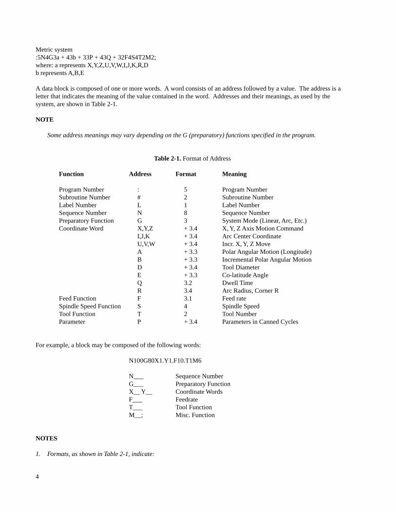
A data block is composed of one or more words. A word consists of an address followed by a value. The address is aletter that indicates the meaning of the value contained in the word. Addresses and their meanings, as used by thesystem, are shown in Table 2-1.
NOTE
Some address meanings may vary depending on the G (preparatory) functions specified in the program.
Table 2-1. Format of Address
Function Address Format Meaning
Program Number : 5 Program NumberSubroutine Number # 2 Subroutine NumberLabel Number L 1 Label NumberSequence Number N 8 Sequence NumberPreparatory Function G 3 System Mode (Linear, Arc, Etc.)Coordinate Word X,Y,Z + 3.4 X, Y, Z Axis Motion Command
I,J,K + 3.4 Arc Center CoordinateU,V,W + 3.4 Incr. X, Y, Z MoveA + 3.3 Polar Angular Motion (Longitude)B + 3.3 Incremental Polar Angular MotionD + 3.4 Tool DiameterE + 3.3 Co-latitude AngleQ 3.2 Dwell TimeR 3.4 Arc Radius, Corner R
Feed Function F 3.1 Feed rateSpindle Speed Function S 4 Spindle SpeedTool Function T 2 Tool NumberParameter P + 3.4 Parameters in Canned Cycles
For example, a block may be composed of the following words:
N100G80X1.Y1.F10.T1M6
N___ Sequence NumberG___ Preparatory FunctionX__ Y__ Coordinate WordsF___ FeedrateT___ Tool FunctionM__; Misc. Function
NOTES
1. Formats, as shown in Table 2-1, indicate:
4

+ a signed value, positive or negative3.x three digits left of the decimalx.3 three digits right of the decimal5 five digits, no decimal
2. The format description is: +3.4 for motion words except A, B, and E which are 3.3. All formats shown are for inchinput. For metric input all formats shown as + 3.4 are + 4.3.
3. Smallest input increment:
Inch system — .0001Metric system — .001Degrees — . 001
Smallest output increment:
Inch — .0001Degrees — .001
4. It is not necessary to use the plus sign for positive values.
5. Decimal points are required in the above list where the decimal is shown (except if the system is run in the BOSS 4-7 compatibility mode). Zeroes to the left of the decimal point and non-significant zeroes to the right of the decimalpoint may be omitted.
6. Values less than the smallest significant input cause an error. For example: X1.23456 is incorrect input.
7. If N, the sequence number is used, it must be the first word in the block.
8. If multiple defined word addresses are used, they must be in the sequence designated for the programmed function.
9. The following format must be used for proper interpretation of information:
N__G__(X,Y,Z, etc.)F__M__(EOB)
Maximum Programmable Dimensions
Table 2-2 lists the maximum programmable dimensions of each address:
Table 2 2. Range of Address
Function Address Range, Inch (Metric)
Program Number : 1 - 65536Label Number L 1 - 9Sequence Number N 1 - 16000000Subroutine Number # 1 - 40Preparatory Function G 1- 199Coordinate Word X,Y,Z,I,J,K + 8388.607 ( + 8388.607)
U,V,W,R,P,DA,B,C,E + 8388.607
Feedrate F .1- 250.ipm (2.- 6350.mmpm)
5

Spindle Speed S 1 - 4200Tool Function T 1 - 24Misc. Function M 0- 99Dwell Time Q .01 - 327.68
NOTE
These dimensions give the maximum control limit, not the mechanical limit of the NC machine tool. For example, X maybe commanded up to 838.8607 inches but the table travel is less.
SPECIAL FEATURES
Definition Blocks
Using a decimal point as the first character in a data block causes the information contained in that block to be executedduring a program search. This feature should be used when a system mode is changed during a program so that after thesearch has been made, the system is in the proper mode.
WARNING
Because data contained in a definition block is executed during program search, words causing slide motion must notbe programmed as definition blocks. This may cause unexpected machine motion which can result in personalinjury.
Block Delete
If it is desired to bypass certain portions of a tape program, a block delete (/) is entered at the beginning of each block oftape information which may require deletion. Using the OPTION key, the operator may enable and disable the blockdelete option. The slash (/) code must be the first character on the data block to be recognized as a delete code.
To disable this function in the control, the DELETE option must be OFF.
This feature could be used, for example, where a trial cut procedure is required. Each block of information within thetrial cut sequence would be preceded by a slash code. The trial cut procedure could then be taken or bypassed at theoperator’s discretion, or as directed by written instructions from the programmer.
This feature is also useful in cases where two parts differ by an optional operation.
CAUTIONCare must be taken to avoid using block delete in lines containing incremental data.
THE COMPOSITION OF THE BLOCK
Words are entered in the following order to create a block of data.
Sequence Number
A sequence number can be specified with up to an eight digit number (1-16000000) following the address N. It issuggested that sequence numbers be in consecutive order, though this is not a requirement. The sequence number isoptional and does not initiate any action from the milling machine. Its main function is for operator convenience and
6
clarity.
Sequence numbers can be searched for using the front panel FIND feature. Sequence numbers can also be used by theoperator to establish a BREAK POINT. System operation stops when a preset break point sequence number is readbefore its execution; the spindle remains on.
It is recommended that sequence numbers be sequential and used to specify important part program blocks such as a toolchange point.
NOTES
The sequence number is also used as a destination for Repetitive Programming.
Preparatory Functions (G-Codes)
A preparatory function is required to change the programmed mode of operation of the control. The letter address Gfollowed by one, two or three digits indicates the mode of operation. More than one preparatory function can beprogrammed in one block of information; however, caution must be exercised as the functions may be self-cancelling,e.g., G0 G1.
For full details, see Chapter 3.
Coordinate Words
Chapter 4 deals with the various coordinate systems that can be used for programming the motion of the available axes:the absolute and incremental coordinate systems are defined as well as polar and spherical coordinates. Coordinateshifts are also explained through the use of preparatory functions (G-Codes) to translate, rotate and scale the coordinatesas well as reflect them by mirror image. Tool length offsets, cutter diameter and fixture offsets are also explained in thischapter.
Feedrate
Feedrate coding is not required in every block since the function is modal. Programmed feeds result in tool motion atthe programmed rate along the vector path programmed. Feeds can be caused to change automatically and decelerationat the end of a block can be eliminated effecting transition at a tangent point at the prevailing servo lag; all for thepurpose of maintaining constant chip load. These features enhance the surface finish and reduce the possibility of dwellmarks.
Auxiliary Machine Control Functions
Chapter 9 deals with three functions: Spindle Speed, Tool Function (see Chapter 4 for TLO and Chapter 7 for CutterCompensation) and Miscellaneous Functions. In the latter case, M-codes cause the interruption of the internalprocessing of data either with or without the operation of functions external to the control or optional accessoryequipment.
7

8

CHAPTER 3PREPARATORY FUNCTIONS
OVERVIEW
G-codes consist of the address G plus a 1 to 3 digit number. The G-codes are divided into two types, those that areeffective only in the block in which it is specified (designated group 0 in Table 3-1) and modal commands that areeffective until another G-code in the same group is executed.
Table 3-1. List of Preparatory Codes
G-Code Group Function0 1 Rapid Traverse1 1 Linear Interpolation (Feed)2 1 Circular Interpolation Clockwise3 1 Circular Interpolation Counterclockwise4 0 Dwell8 11 Modal Deceleration Override Off9 11 Modal Deceleration Override On12 0 Helical Interpolation CW13 0 Helical Interpolation CCW17 2 XY Plane Selection18 2 ZX Plane Selection19 2 YZ Plane Selection22 0 Circular Interpolation, Fillet Input CW23 0 Circular Interpolation, Fillet Input CCW30 3 Mirror Image Off31 3 Mirror Image X On32 3 Mirror Image Y On40 4 Cutter Diameter Offset Off41 4 Cutter Compensation Left42 4 Cutter Compensation Right44 5 Cutter Compensation, Normal Feedrate45 5 Cutter Compensation, Modify Feedrate48 12 Corner Rounding in Cutter Comp Off49 12 Corner Rounding in Cutter Comp On70 6 Input in Inch71 6 Input in Millimeter72 7 Transformation Off73 7 Transformation/Rotation, Scaling74 8 Multi-quadrant Circle Input Off75 8 Multi-quadrant Circle Input On77 1 Zig-Zag Mill Cycle78 1 Pocket Mill Cycle79 1 Bore Mill Cycle80 1 Drill Cycle Off81 1 Z Cycle, Drill (Feed In, Rapid Out)82 1 Z Cycle, Spot Face (Feed In, Rapid Out)83 1 Z Cycle, Deep Hole (Peck, Rapid Out)84 1 Z Cycle, Tap (Feed In, Feed Out)85 1 Z Cycle, Bore (Feed In, Feed Out)86 1 Z Cycle, Bore (Feed In, Stop-Wait, Rapid Out
9

Table 3-1. List of Preparatory Codes (Continued)
G-Code Group Function87 1 Z Cycle, Chip Break (Peck, Rapid Out)89 1 Z Cycle, Bore (Feed In, Dwell, Feed Out)90 9 Absolute Programming91 9 Incremental Programming92 0 Preset Part Programming Zero Point94 13 Feedrate Per Minute Mode95 13 Feed Per Spindle Revolution (pitch) mode.96 10 Restore Base Part Program Coordinate System97 10 Set Work Coordinate System99 0 Deceleration Override170 1 Outside Frame Mill171 1 Inside Frame Mill172 1 Pocket Frame Mill173 1 Outside Face Mill174 1 Inside Face Mill175 1 Outside Circle Mill176 1 Inside Circle Mill177 1 Pocket Circle Mill179 1 Slot Mill181-189 1 Z Cycle (Same as G81-G89) Multi-Hole191-199 1 Z Cycle (Same as G81-G89) Frame of Holes
Multiple G-codes may be programmed in a block of data provided that they are from different groups.
The initial start up conditions of the preparatory functions are shown in Table 3-2.
Table 3-2.Power On and Reset State of G-Codes
G-Code Group Function0 1 Rapid Traverse8 11 Modal Deceleration Override Off17 2 XY Plane Selection30 3 Mirror Image Off40 4 Cutter Compensation Off45 5 Cutter Compensation, Modify Feedrate49 12 Corner Rounding in Cutter Comp On70/71 6 Input in Inch or Metric, Non-volatile72 7 Transformation Off75 8 Multi-quadrant Circle Input On90 9 Absolute Programming94 13 Feedrate Per Minute mode96 10 Base Coordinate System
G0 — RAPID TRAVERSE POSITIONING
Code G0 sets the rapid traverse positioning mode and sets the feedrate to the rapid traverse rate. The programmedfeedrate is modal and is re-established when G0 is deactivated. Input data may be either absolute or incremental.
10

When a part program block calling for axis motion is executed with G0 active, the control does the following:• Generates linear X, Y motion towards the programmed endpoint.
• If a Z up move is programmed (+Z), the Z move occurs then the XY move. If a Z down move isprogrammed (–Z), the XY move occurs first, then the Z move.
Figure 3-1. 3-Axis Rapid Traverse Move
The format of the G0 command is: G0X__Y__Z__;
Example, Figure 3-1:
N10G90G0X3.Y - 2.Z0; PT1N20Z- 1.; PT2N30X6.Y4.Z - 3.; PT3
or
N10G90G0X3.Y - 2.Z0.; PT1N20W- 1.; PT2N30U3.V6.Z - 3.; PT3
G1 — LINEAR INTERPOLATION
G1 Code sets the Linear Interpolation mode. The format of the G1 command is:
G1X__Y__Z__F__;
Where X__Y__Z__ defines the endpoint of the move to be made. Simultaneous XYZ motion along a linear (straightline) path occurs at the feedrate defined by the F__ word.
PT1 (3,-2,0)PT2 (3,-2,-1)
PT3 (6,4,-3)
Z
Y
X
11
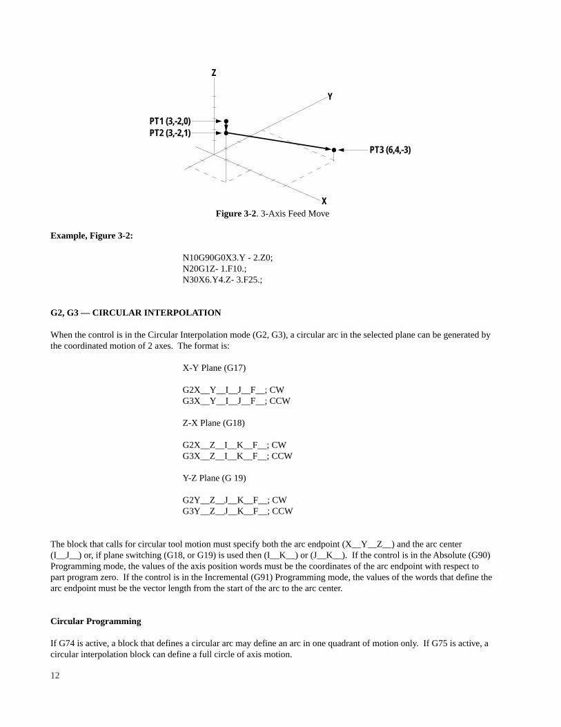
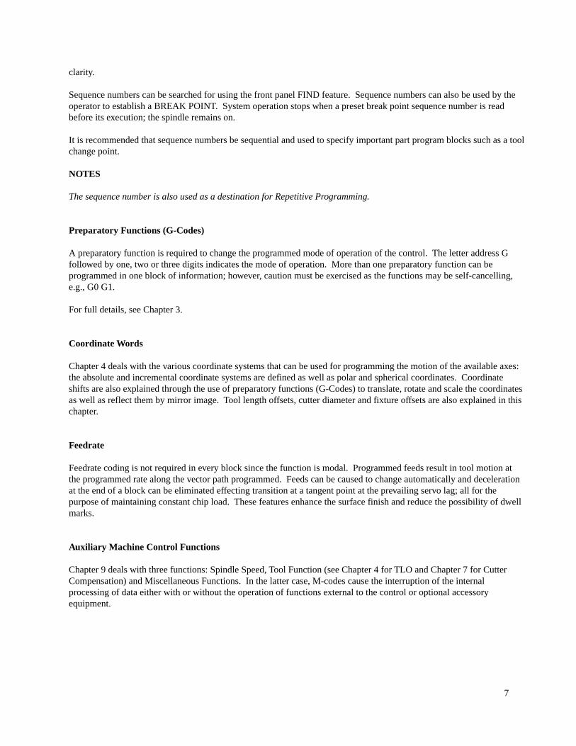
Figure 3-2. 3-Axis Feed Move
Example, Figure 3-2:
N10G90G0X3.Y - 2.Z0;N20G1Z- 1.F10.;N30X6.Y4.Z- 3.F25.;
G2, G3 — CIRCULAR INTERPOLATION
When the control is in the Circular Interpolation mode (G2, G3), a circular arc in the selected plane can be generated bythe coordinated motion of 2 axes. The format is:
X-Y Plane (G17)
G2X__Y__I__J__F__; CWG3X__Y__I__J__F__; CCW
Z-X Plane (G18)
G2X__Z__I__K__F__; CWG3X__Z__I__K__F__; CCW
Y-Z Plane (G 19)
G2Y__Z__J__K__F__; CWG3Y__Z__J__K__F__; CCW
The block that calls for circular tool motion must specify both the arc endpoint (X__Y__Z__) and the arc center(I__J__) or, if plane switching (G18, or G19) is used then (I__K__) or (J__K__). If the control is in the Absolute (G90)Programming mode, the values of the axis position words must be the coordinates of the arc endpoint with respect topart program zero. If the control is in the Incremental (G91) Programming mode, the values of the words that define thearc endpoint must be the vector length from the start of the arc to the arc center.
Circular Programming
If G74 is active, a block that defines a circular arc may define an arc in one quadrant of motion only. If G75 is active, acircular interpolation block can define a full circle of axis motion.
PT3 (6,4,-3)
PT1 (3,-2,0) PT2 (3,-2,1)
X
Z
Y
12

NOTE
The reset program condition for the DX-32 operational mode is G75, multi-quadrant input. The BOSS 4-7 Compatibilitymode sets G74, single quadrant input as the default condition.
If G75 is active and G90 (absolute data input) is also active, I__, J__, K__ specifies the arc center coordinates withrespect to part program zero. If G91 (incremental data input) is active, I__, J__, K__ specifies the signed distance fromthe arc startpoint to the center of the arc.
If G74 is active, I__, J__, K__ specifies the unsigned magnitude of the distance from the arc startpoint to the arc centerin G90 (Absolute) or G91 (Incremental) mode.
NOTES
1. I and J values (even zero) must be stated when G73 (transformation) or G75 (multi-quadrant) are active.
2. To program an arc of 360 degrees (complete circle), either the X, Y or Z endpoint must be programmed together withthe arc center.
3. When using circular interpolation in either the XZ (G18) or YZ (G19) plane, the K value must be input even if it iszero.
Circular Interpolation by Radius Programming
In the XY plane, circular interpolation can be programmed by specifying the radius (R_) instead of the arc center if thearc is 179.998 degrees or less. The format is:
G2X__Y__R__F__G3X__Y__R__F__
Where X__ Y__ are the arc endpoints as described above, R is the arc radius, and F is the feedrate.
Figure 3-3. Circular Interpolation in the XY Plane
PT3 PT2
2.
R1
R2
PT1
7.5.4.3.
4.
13

Example, Figure 3-4:
G75G90 (Multi-quadrant absolute)
N10G75G90G0X7.Y2.Z0;Rapid traverse to point PT1N20G3X5.Y4.15.J2.F1 5.; 90 degrees CCW arc to point PT2N30G2X3.14.J4.; 180 degrees CW arc to point PT3
N10G75G90G0X7.Y2.Z0;Rapid traverse to point PT1N20G3X5.Y4.R2.F15.; PT2 using radiusN30G2X3.14.J4.; PT3 180 degree arcG75G91 (Multi-quadrant incremental)
N10G75G0X7.Y2.Z0N20G91G3X - 2.Y2.1 - 2.J0F15.; PT2N30G2X - 2.1 - 1.J0; PT3
N10G75G0X7.Y2.Z0N20G91G3X - 2.Y2.R2.F15.; PT2 using radiusN30G2X - 2.1 - 1.J0; PT3
G4 — DWELL
G4 Code specifies or invokes a dwell. The format for specifying the dwell time is:
G4/__ G4Q__
Where /__ or Q__ is the dwell time.
NOTE
The range of dwell time is .01 to 327.68 seconds. Trailing zeroes may be omitted in the dwell value. For example, adwell of 10 seconds may be programmed as G4/10. ;the decimal point is required.
The dwell time value is modal once it is specified. Dwell is invoked on a non-modal basis:
• At the end of the Z feed, move in a G82, G84 or G89 cycle.• When a G4 code is programmed in a block, that does not call for axis motion.
A G4/__ or G4Q__ defines a dwell but does not cause a dwell to occur until invoked later by G4 statement.
G8, G9 — MODAL DECELERATION OVERRIDE
Programming G9 is equivalent to having a G99 (non-modal) on every line. There is no automatic deceleration at the endof each block. G8 restores automatic deceleration, essential for rapid traverse blocks.
For details, see Chapter 8.
14

G12, G13 — HELICAL INTERPOLATION
Circular interpolation in the XY plane can be synchronized with linear interpolation in the Z-axis. The format requiresthat the tool be positioned at the start point of the helix using Polar Coordinates:
G0(G1)R__I__J__A__; Move to Helix Start PtG12(G13)A__Z__F__; Do Helix
Where A__ is the total number of degrees of helical travel and Z is the absolute depth of travel. G12 generates aclockwise helix, G13 generates a counterclockwise helix.
NOTES
1. Cutter compensation cannot be used with helical interpolation.
2. The range of A is from 1. to 65535. degrees. For example, a thread with 2 1/2 turns would be programmed as (360.*2.5 = 800. degrees) A800.
3. Helical interpolation cannot be transformed.
Figure 3-6. Helical Interpolation
Example, Figure 3-6:G0R4.I0J0A270.Z0; Move to Pt. 4G12A90.Z3.F40.; Helical to Pt. 2
Spiral Interpolation
This is a special case of interpolation using polar data in which the end radius is not the same as the start radius. Theradius increases or decreases linearly as a function of the angle.
For example:G0R1.I050A0G13R2.A270.Z0F20.2
This causes an outward spiral over 270 ° from 1” to 2” radius.
Z
Y
X
R4.
Pt. 2
Pt. 4Z3
15

G17, G18, G19 — PLANE SWITCHING
Circular interpolation is effective in the XY, YZ or ZX planes by preparatory codes as follows:
G17 = XY PlaneG18 = ZX PlaneG19 = YZ Plane
NOTE
1. G18 or G19, if used, must be programmed before the direction of circular interpolation.
2. The feedrate word F__ defines the constant vector velocity required of the tool. Feedrate is modal and may havebeen defined in an earlier block of data.
3. Neither Polar Coordinates nor Cutter Compensation may be used in the XZ (G18) or YZ(G19) planes.The clockwise and counterclockwise directions for the XY, ZX, YZ planes are shown in Figure 3-4. (Always look in theminus direction of the axis not in use.)
Figure 3-4. Planes for Circular Interpolation
ArcCenter
Plan View
G17XY Plane
CWG02
X+
Y+JStartPoint
I
ArcCenter
CWG02
X+
Z+StartPoint
View from Rear of Machine
View from RHS of Machine
G18ZX Plane
K
ArcCenter
CWG02
Y+
Z+StartPoint
G19YZ Plane
K
I
J
16

NOTE
The opposite view in the G18 and G19 planes was in effect with BOSS 4-7.
Figure 3-5. Circular Interpolation in the ZX Plane
NOTES
The following procedures must be followed when programming XZ (G18) or YZ (G19) Circular.
1. Program to the center of the radius of the Ball End Mill.
2. Plane selection (G18 or G19) must come before directional modifier (G2 or G3) in both the BOSS 4-7 compatibilitymode and the DX-32 operational mode.
3. Radius programming may be used in the XZ (G18) and YZ (G19) planes.
Example program for the part shown in Figure 3-5 using a 1/4 dia. Ball End Mill
Tool Positionin Figure 3-5 N1G0G90G75X - 3.Y3.T1 M6
1 N5X.5Y0Z1.175N10G1Z1.125F5.0= N30/100 ...................................... Start of Loop
2 N15G18G3X1.618Z.125I.5K.125
.5
2.0
2.0
.5
1.0R
.125Fillet
Absolute CoordinatesPt X Z12345
.51.61801.6180
.5
.5
1.125.125.1251.1251.125
ArcCenter
.01
.01
-X
XO, YO, ZOOrigin
-Y
Z
2
1
4
5
3
Pt.
2
Z
X a bc
a = 1.125
c = a - b2
1.125 - .1252
c = 1.1180
c =
Pt. 2/3 = C + .5 = 1.6180
2
2
b = .125
Calculation Method to Obtain"X" Coordinate of Points 2 and 3
Program the Part Shown Using1/4 Dia. Ball End Mill
17
3 N20G1V.014 N25G18G2X.5Z1.125I.5K.125F5.05 N30G1V.01 .................................... End of Loop
N35G0X - 3.Y3.M2N5 and N10 position the cutter to Tool Position. 1.
= N301100 calls the Loop that executes N15 through N30 (100) one hundred times.
N15 selects the XZ plane (G18), and sets the system in circular (G3). The X and Z values are the absolute coordinatesof Tool Position 2 and the I and K values are the Arc Center coordinates.
N20 moves an incremental distance (.01) from Tool Position 2 to Tool Position 3 in the Y-axis (The V word impliesincremental mode).
N25 resets the system in the XZ plane (G18) and circular (G2). The X and Z values are the absolute coordinates of ToolPosition 4 and the I and K values are the coordinates of the Arc Center.
N30 is the last block of the loop which positions the cutter to Tool Position 5 ready to begin the next execution of theloop.
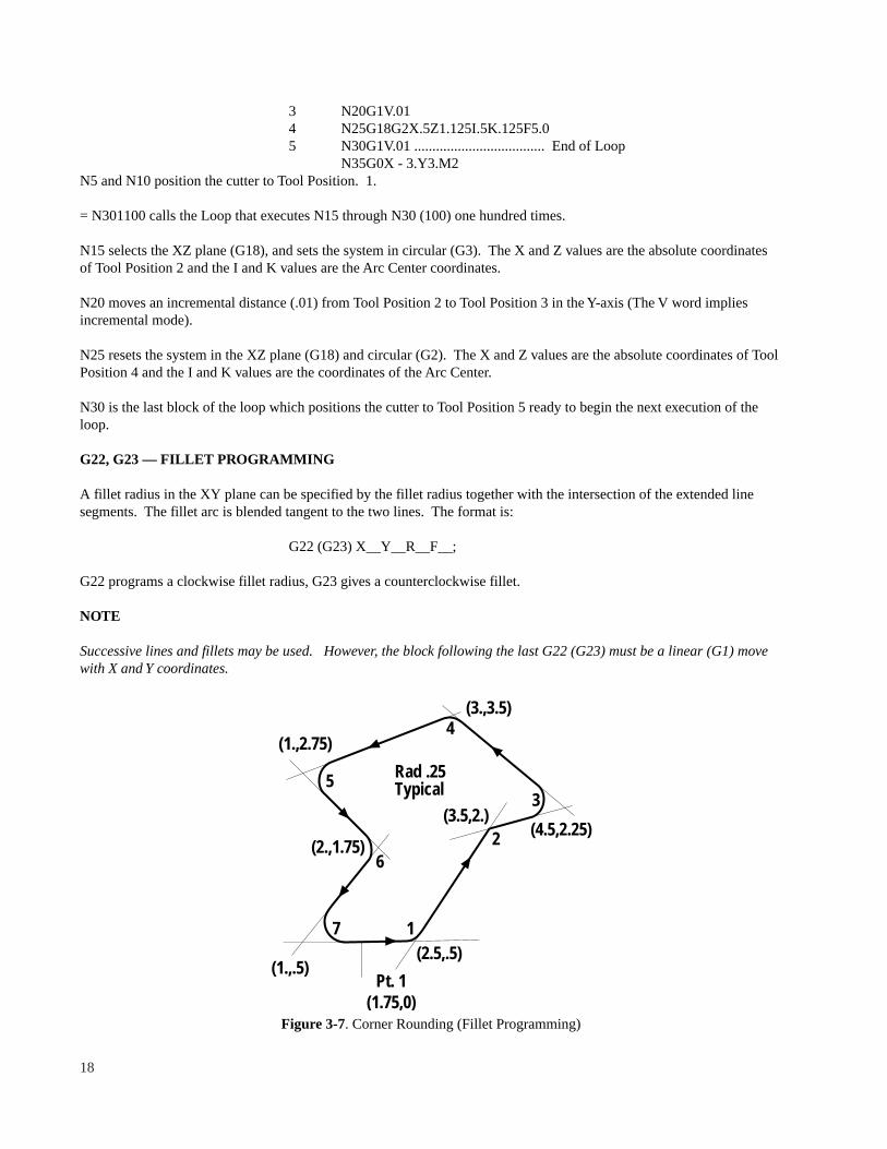
G22, G23 — FILLET PROGRAMMING
A fillet radius in the XY plane can be specified by the fillet radius together with the intersection of the extended linesegments. The fillet arc is blended tangent to the two lines. The format is:
G22 (G23) X__Y__R__F__;
G22 programs a clockwise fillet radius, G23 gives a counterclockwise fillet.
NOTE
Successive lines and fillets may be used. However, the block following the last G22 (G23) must be a linear (G1) movewith X and Y coordinates.
Figure 3-7. Corner Rounding (Fillet Programming)
(1.,2.75)
(3.,3.5)
(2.,1.75)
5
6
4
3
7 1
2
(1.,.5)Pt. 1
(1.75,0)
(2.5,.5)
(4.5,2.25)
Rad .25Typical
(3.5,2.)
18

Example, Figure 3-7:
N5G0X1 .75Y0Z0; Move to Pt. 1N10G1X1.75Y.5F20; Feed to WorkN15G23X2.5Y.5R.25; Do Fillet 1N20G22X3.5Y2.0R.25; Do Fillet 2N25G23X4.5Y2.25R.25; Do Fillet 3N30G23X3.0Y3.5R.25; Do Fillet 4N35G23X1.0Y2.75R.25; Do Fillet 5N40G22X2.Y1.75R.25; Do Fillet 6N45G23X1.Y.5R.25; Do Fillet 7N50G1X1.75Y.5; Linear to Exit Pt.
G30, G31, G32 — MIRROR IMAGE
These codes act to reverse the sign of the direction of X and/or Y axis motion, thus enabling the generation of mirrorimages of the programmed part.
G30 = Mirror Image CancelG31 = Mirror Image X-AxisG32 = Mirror Image Y-Axis
For full details and examples, see Chapter 4.
G40, G41, G42 — CUTTER DIAMETER COMPENSATION
This function is for automatically compensating the tool path to the right or left of the programmed path by a distanceequal to the radius of the tool used.
G40: Cutter Diameter Compensation, CancelG41: Cutter Diameter Compensation, LeftG42: Cutter Diameter Compensation, Right
Tool diameter values can be specified either via manual data input or by inserting them in the part program in the form:
T//Tool Diameter, T__D__;
The maximum tool diameter that can be entered is + 3.2768 inch (83.231 mm).
For full details, see Chapter 7.
G44, G45 — CONSTANT SURFACE FEED
When a linear feed is programmed in conjunction with work surface programming, the value of cutter diametercompensation entered causes this feedrate to be modified around a radius. Constant surface feed is imposed by G45 toreduce the feed around an inside radius and increase the feed around an outside radius as a function of the cutterdiameter compensation value in effect. Cancel with G44.
For full details, see Chapter 8.
19

G48, G49 — CORNER ROUNDING IN CUTTER COMPENSATION
When corner rounding is set to ON (G49), all adjacent non-tangent moves are connected automatically by an arc move.If corner rounding is set to OFF (G48), adjacent moves are carried out as they are defined.
Refer to the examples and notes at the end of Chapter 7.
G70, G71 — INCH/METRIC CONVERSION
G70 and G71 codes specify whether data is to be input in either inch or metric.
Unit Least InputG-Code System Increment Feedrate
70 Inch .0001 in/min71 Metric .001 mm/min
NOTES
1. A block that contains either G70 or G71 cannot contain any other part program word.
2. Data is stored in the control as inch values. Input values in mm are converted to inch internally.
3. The block following a change in the dimension system must redefine the X, Y, Z and (R,I, J, if used) values in theunits of the new data input system (G70 or G71).
The dimensional system last used is in effect when power is turned ON, i.e., the mode is non-volatile.
G72, G73 — TRANSFORMATION FUNCTION
With this function, geometrical shapes specified by part programs may be rotated and can also be enlarged or reduced inany desired ratio. The range of reduction and enlargement is from .001 to 99.999 times.
G72: Transformation off
Further information on coordinate transformation is found in Chapter 4.
G74, G75 — ARC CENTER IN CIRCULAR PROGRAMMING
These two methods of locating the arc center when circular interpolation is programmed allow:
G74 = Single Quadrant Circular InterpolationG75 = Multi-Quadrant Circular Interpolation
G77, G78, G79 — MILLING CYCLES
These canned cycles (unlike the G170 series) do not include cutter diameter compensation. There are three simplifiedforms of cycles in this series:
G77 = Zig-Zag Mill (Facing) CycleG78 = Pocket Milling Cycle
20

G79 = Bore (Internal Circular) Mill CycleFor full details, see Chapter 6.
G80-G87, G89 — DRILLING CYCLES
These Z-axis canned cycles perform various versions of drill, deep drill, tapping and boring cycles.
Full details are contained in Chapter 5.
G90, G91 — ABSOLUTE/INCREMENTAL PROGRAMMING
G-codes select either absolute or incremental programming
G90: Absolute ProgrammingG91: Incremental Programming
See the details starting in Chapter 3 and also in Chapter 4.
G92 — PROGRAMMING OF ABSOLUTE ZERO POINT
In SETUP, the SET command establishes the base part program coordinate system. The G92 code enables redefiningthe local part program zero by creating an offset value which is then summed with subsequent part program data. Theformat of the offset (G92) command is:
G92X__Y__Z__;
Where X__Y__Z__are the new part program coordinate values for the current coordinate point. The G92 offset value isequal to:
New G92 value — current coordinate value + old G92 value.
NOTES
1. No motion occurs as a result of a G92 block.
2. G92 must be programmed when in the absolute mode (G90).
3. The display shows the part program coordinate system.
4. Do not program G92 when cutter compensation is turned on.
5. It is recommended that the fixture offset command (G97) be used for translating the part program when multiplefixtures are used. G92 and G97 may be used together in a program. The G97 command establishes a fixturecoordinate system and the G92 command establishes a local coordinate system within the fixture coordinate system.
6. The G92 offset remains in effect until a new G92 offset is input.
G94, G95 — FEEDRATE UNITS
The G95 command (feedrate per spindle revolution) may be used for any linear or circular move in addition to thetapping cycle. The G95 provides an alternate means of specifying feedrates. Note that the G95 command works only
21

with desired spindle speeds, it does not self-adjust if the spindle speed varies due to load or operator actions. The pitch(Z axis travel per spindle revolution) is entered with a F word address in either inch or millimeters per spindlerevolution). The default mode is G94 (feedrate per minute). Details are contained in Chapter 4.
G96, G97 — FIXTURE OFFSETS
The G97 command with new coordinate definition translates the existing program to a new program origin by theoffsetting of data an incremental amount. Absolute coordinates can also be used. G96 cancels the offset .
For more details on using the G96 and G97 commands, see the section in Chapter 4 titled “Translation”.
G99 — DECELERATION OVERRIDE
Deceleration at the end of a motion block may be overridden by programming G99 in the program line.
For details, see Chapter 8.
G170, G177, G179 — MILL CYCLES
These functions enable machining frequently used shapes with one part program block.
The following mill cycles are available:
G170: Outside rectangular frame with corner radiusG171: Inside rectangular frame with corner radiusG172: Rectangular pocket mill ends with G171 automatically for finish passG173: Face mill rect. shape (zigzag path)G174: Pocket mill rect. shape (zigzag path)G175: Circle mill outside a bossG176: Circle mill inside a circular shapeG177: Circular pocket mill ends with G176 automatically for finish passG179: Slot mill
The mill cycles include an approach and departure move tangent to the shape programmed, roughing and finish cuts anda Z-axis step capability for deep shapes. In addition, the cycles as defined use the tool data table to generate a diametercompensation tool path.
Details are in Chapter 6.
G181-G187, G189 — DRILL PATTERNS — ROWS
A series of Z-axis cycles equivalent to the G81-G89 series is available with these 3 digit preparatory function. The rowof holes may be in a straight line at any angle or may be a circular row in the form of a bolt circle.
For details, see Chapter 5.
G191, G197, G199 DRILL PATTERNS — FRAME
A series of Z-axis cycles equivalent to the G81-G89 series is available with these 3 digit preparatory function. Theframe of holes is a rectangular pattern parallel to the XY axes and may contain any number of holes.
For details, see Chapter 5.
22

CHAPTER 4COORDINATE WORDS
OVERVIEW
A coordinate word specifies an axis movement and consists of the address of the axis to be moved and the valueindicating the direction of motion and the distance. See Table 4-1.
CONTROLLED AXIS
Three axes (X,Y,Z) are controlled by the system. In rapid, if the programmed Z move is higher than the current Zposition, a Z move occurs first, then the X and Y axes move. If the programmed Z move is lower than the current Zposition, the Z move occurs after the X, Y move. For linear interpolation, three axes (X,Y,Z) are controlledsimultaneously. For circular interpolation, two axes are controlled simultaneously, either (X Y) or (X Z) or (Y Z)dependent upon the plane designated by the programmer. For helical interpolation, circular interpolation in the X, Yplane occurs simultaneously with coordinated Z motion.
COORDINATE SYSTEMS
Machine Coordinate SystemFor the BSX system, the axis travel limits are:
X-Axis (table) 17.7 inchesY-Axis (saddle) 12.2 inchesZ-Axis (quill) 16.1 inches
During start up, the X, Y and Z axes are moved to the “Home” position, which is defined as the machine zero coordinatepoint. The quill is in the uppermost position. The distance from the machine zero coordinate point to any point on thetravel of the axes is called the machine coordinate point (or machine point).
NOTE
The “Home”position for X, Y and Z is mechanically set by the position of the “Home” switches and a zero referencemark on the axis feedback encoders.
Part Program Coordinate System — Figure 4-1
When programming a part, the coordinate system must be established. Additionally, since the workpiece may be locatedat any arbitrary position on the table, the relationship between the machine coordinate system and the part programcoordinate system must be established. This relationship is entered into the system by the operator during setup.
In the example, the following dimensions are known:
X-distance from bottom left hand edge of part toX-axis part program zero = 2.5.
Y-distance from bottom left hand edge of part toY-axis part program zero = 1.
23

Table 4-1. Coordinate Word Addresses
Address of Coordinate Word MeaningBasic Axes
X X-Axis Move Absolute or IncrementalY Y-Axis Move Absolute or IncrementalZ Z-Axis Move Absolute or IncrementalU X-Axis Move IncrementalV Y-Axis Move IncrementalW Z-Axis Move Incremental
Parameters for Circular Interpolation (G75)
I,J,K Absolute: Coordinates of center of circle.Incremental: Signed distance from arc start point to arc center
Polar and Spherical Coordinates
R Pole RadiusI,J,K Absolute: Coordinates of center of pole.
Incremental: Signed distance from pole start point to center of pole.A Angular Distance, (Longitude) Degrees Absolute or IncrementalB Angular Distance, (Longitude) IncrementalE Angular Distance, (Colatitude) Degrees Absolute
Refer to preparatory function descriptions for additional coordinate words used in special control program features.
Using a .20” edge finder, locate the X coordinate for the bottom left hand edge of the part. The X value of the machinecoordinate point can be read as 1.90n. Using the SET XYZ command, an X value of - 2.60” is set into the control(distance along the X-axis from the left hand edge of the part to the part program zero point = 2.50” plus .10” to thecenter of the edge finder) to establish where the X-axis part program zero is located on the table.
A similar process can be used to set the distance from the bottom left hand edge to the Y-axis part program zero. In thisexample, this value would be -1.10” using a .20” edge finder.
Once the location of the part program coordinate system is set by the operator, it is stored in non-volatile memory, thevalue is retained when power to the system is turned off. After homing the axes during start up, a MOV XY command toX = 0, Y = 0 causes the axes to move to part program zero.
The SET XYZ key may be used to define the location of the base part program coordinate system. A G92 commandmay be used within a part program to shift the location of part program zero. A G97 command allows establishingfixture offsets by shifting the part program coordinate system by an amount equal to the distance between the base partprogram coordinate system and the desired work part program coordinate system.
24

Figure 4-1. Part Program Coordinate System
Clear Point The SET CLR PT key allows the operator to store an XY axis position as a convenient point for changingtools. The M20, M21, M22, and M26 commands stop part program execution and also send the XY axes to the clearpoint. The quill is retracted prior to moving the X and Y axes. The clear point is stored in machine coordinates.
Software Limits
In the control system, all motion is based on the machine coordinate system. The part program interpreter adds an offsetto all part program dimensions to transform them from the part program coordinate system to the machine coordinatesystem. A check is made by the part program interpreter before each move is made to determine if the move is withinthe limits of axis motion. Exceeding these limits causes an error message and the system suspends part programexecution.
TOOL LENGTH OFFSET
Tool length offsets enable the operator to enter a value in the system so that adjustments can be made to allow for thedifference between the tool length assumed by the programmer and the actual length of the tool used. Tool lengthoffsets are useful when:
• Cutter preset dimension is not exact. This is particularly effective with end mills in end millholders and also with tools which draw up into a collet.
• Change of reference plane.
• A new or reground cutter replaces the tool in use.
For details, see the Operating Manual.
Machine Pt.X = 9, Y = 6
9"
2"
6"
Machine pt.X = 0, Y = 0
1"
X-Axis
Y-Axis
2.5"
Machine Pt.X = 4.5, Y = 5Part ProgramX = 0, Y = 0
25

NOTES
1. Tool length offsets are unsigned numbers.
2. If a tool length offset already exists in the tool table, it cannot be overwritten by part program data.
3. The maximum tool length offset that can be input is 6.5536 inches (166.461mm).
4. 24 TLOs are allowed.
5. The tool length offset is automatically set into the system when a tool change (M6,M26) command is executed.
6. The diameter offset is automatically set in the system when a T(tool number) command is executed.
NOTES
If the Part Coordinate at the workpiece top is other than zero, the ZABS register can also be preset (G92) to any valueconvenient to the programmer. The TLO value defines the TLO Reference Plane from which all Part Programscommence. After Z-axis G92 is implemented, the offset reference plane becomes ZABS = 0.0 for the remainder of theprogram.
Figure 4 2. Translating the Z Coordinates
Programming a shift in the Z zero plane is illustrated in Figure 4-2.
Gauge Line
TLO Value
ZABS = 0.0
ToolSetting
Distance
[G92 Z (Value)]Trans
Dimension
Workpiece
26

Figure 4-3.Incremental and Absolute Programming— Linear
ABSOLUTE AND INCREMENTAL PROGRAMMING
The distance of tool travel in each axis may be input as either absolute or incremental data. Using incrementalcommands (G91), the data in a word is the distance along the designated axis from the existing position to the desiredposition. Using absolute commands (G90), the data in a word represents the coordinate value of the point from partprogram zero.
For the example shown in Figure 4-3, programming in Incremental mode would be:
G91G0X - 5.Y4.
Programming in Absolute mode would be:
G90G0X4.Y7.
U, V, W are incremental X, Y, Z moves respectively. Thus, it is possible to program the above example as:
G90G0U - 5.V4. G91 G0U - 5.V4. G90G0X4.V4.
In addition, the center point of an arc may be described as either an incremental or absolute dimension. In Incrementalmode, the center of the arc is designated as the distance from the start point of the arc to the arc center. In Absolutemode, the center of the arc is designated by its coordinates from the part program zero. See Figure 4-4.
For example, in Incremental mode, the arc would be programmed:
G91G3XOY - 4.I0J - 2.F10.0
In Absolute mode, the arc would be programmed:
G90G3X - 2.Y1.I - 2.J3.F10.0
Figure 4 4. Incremental and Absolute Programming — Circular
Y7.0
3.0
4.0 9.0 X
End Point
Start Point
27
-X
Start Point
CircleCenter
End Point2.
5.
3.

POLAR COORDINATES
Besides rectangular coordinates, polar coordinates may be used to designate point locations. The location of a point isdesignated by the radius from the pole center and by the angle the radius makes with reference to the positive X-axis.See Figure 4-5.
Example:In Incremental mode, this would be:
NlG92A0.; Preset A=O.N2G91R1.3751-2.J-.25.; Define Pole CenterN3G81A44.Z.55F20.; Drill 1st HoleN4A166.; Drill 2nd HoleN5G90G0X.5Y.75; Goto End Pt
NOTES
1. I and J the pole center are defined incrementally (except if the system is in the BOSS 4-7 compatibility mode). InAbsolute mode, this would be:
N0G92A0.N1G90R1.3751- 1.5J.5; Define Pole CenterN2G81A44.Z.55F20. Drill 1st HoleN3A210.; Drill 2nd HoleN4G0X.5Y. 75; Goto End Pt.
2. The range of A is + 719.999 to - 359.999 degrees.
3. Positive angles are measured Counterclockwise from the positive X-axis, negative angles are measured Clockwisefrom the positive X-axis.
4. Polar coordinate data can be rotated, scaled and used in conjunction with cutter diameter compensation.
Figure 4-5. Polar Coordinates
XP2
30°
1.5
.5
P1
44°
Y
Part ProgramZero
Drill (2) .25 Dia. Holeson 2.750 BCD, .5 DP
Start & End PointX = .5, Y = .75
28

θ° Radius1 10 R = .9502 20 R = .9303 30 R = .9004 40 R = .8905 50 R = .8806 60 R = .8907 70 R = .9108 80 R = .9409 90 R = .980
Figure 4-6. Cam Track
Example, Figure 4-6:
N1G0G90X0.Y0.T1 M6; Start Up PtN5G92A0.; Preset A = 0.N10R.9810.J0.A150.; Goto A = 150.N15G13A30.Z - .12F12. Helix Down into PartN20G3A0.; Circle CCW to 0°N25G 1 R.95A10.; Point 1N30R.93A20.; Point 2N35R.9A30.; Point 3N40R.89A40.; Point 4N45R.88A50.; Point 5N50R.89A60.; Point 6N55R.91A70.; Point 7N60R.94A80.; Point 8N65R.98A90.; Point 9N70G3A185.; Circle CCW to 185°N75G13A30.Z.135; Helical Out of PartN80G0X0Y0M2
SPHERICAL COORDINATES
The spherical coordinates of a point are its radius vector R, its center from the origin along the X, Y, Z axes designatedby I, J, K dimensions, the angle E between the radius vector and the Z-axis, and the angle A between the projection ofthe radius vector on the XY plane and the X-axis. The angle E is called the colatitude and the angle A is the longitude.The angle E is an absolute value between 0 and 359.999 degrees, the angle A is measured with reference to the positiveX-axis.
29
9 8 75
6
4321
4
2.000
2.000
4
1/2.100
.250 Slot
.98R

Example:N100G9013.5J-1.5K0.N110G0R2.E45.A-30.
Figure 4-7. Spherical Coordinates
TRANSFORMATIONS
Under certain conditions, it is useful to perform the following operations:
• Rotate the points on the cutter path through an angle in the XY plane.
• Scale the points on the cutter path by a given amount.
• Translate the cutter points to a different reference system. The transformation functions providethese capabilities.
The order of transformation is: Rotation, Scaling, Mirror Image and then Translation.
Rotation
Rotation of a programmed part shape can be done by inserting the code (G73) followed by the angle (A degrees) throughwhich the shape is to be rotated. The XY coordinate around which the part is rotated is always the origin or X zero Yzero absolute coordinates of the part. The preparatory function code (G72) turns transformation off.
Features of Rotation:
1. The star shown in Figure 4-8 can be developed in the manner shown, but the entire shape can form an inner nestwith an outer command to rotate through any angle desired.
2. A shape containing Z-axis motion (pocket with a sloping bottom) can be routed and still maintain the Z-axis motionat the appropriate places.
3. Though the example in Figure 4-8 shows linear motion only, a part with circular interpolation input can also berotated. See Figure 4-9 for a Geneva Mechanism Rotor.
A
P (X, Y, Z)(E, A)
R
Q
OY
Z
EZ
X
Y
30

The four parts of the star are developed in Macro #1, then the entire star is rotated through an angle of 15 degrees.
Nl0G0G90X-4.5Y3.75T1M6N15G92A0#1N20X.5Y0N25Z-.05=N60/4N40G90G1X1.5Y1.5F12.0N50X0Y.5N60G91G73A90.0N65G0G90G72.Z.05
=#1N70G73A15.0=#1N80G0G90G72X-4.5Y3.75M2
To develop the four parts of the star:
(1) N20X.5Y0N 25Z-.05N30G92A0= N60/4
(2) N40G90G1X1.5Y1.5F12.0N60G91G73A90.0N70G0G90G72X
-4.5Y3.75Z.05
Figure 4-8. Coordinate Rotation
31
3
2
1XOYO
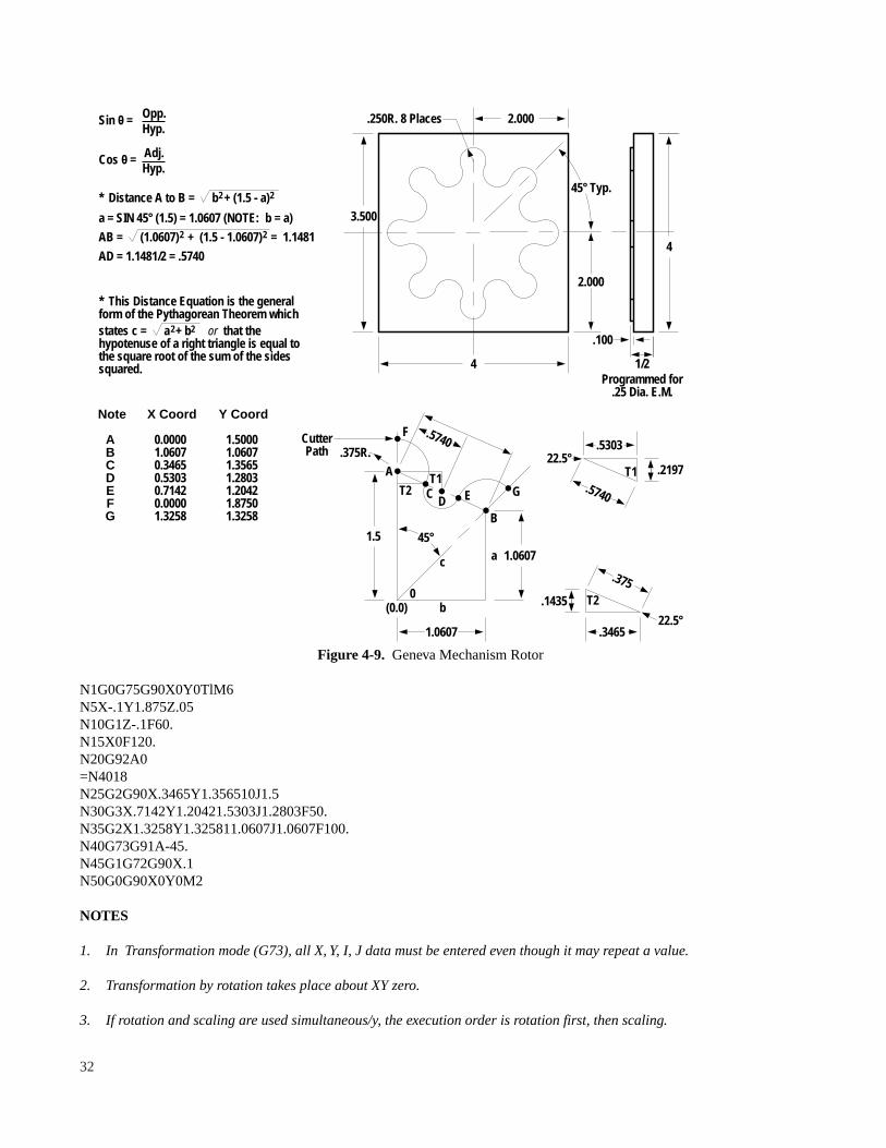
Figure 4-9. Geneva Mechanism Rotor
N1G0G75G90X0Y0TlM6N5X-.1Y1.875Z.05N10G1Z-.1F60.N15X0F120.N20G92A0=N4018N25G2G90X.3465Y1.356510J1.5N30G3X.7142Y1.20421.5303J1.2803F50.N35G2X1.3258Y1.325811.0607J1.0607F100.N40G73G91A-45.N45G1G72G90X.1N50G0G90X0Y0M2
NOTES
1. In Transformation mode (G73), all X, Y, I, J data must be entered even though it may repeat a value.
2. Transformation by rotation takes place about XY zero.
3. If rotation and scaling are used simultaneous/y, the execution order is rotation first, then scaling.
2.000
4
4
3.500
2.000
45° Typ.
.250R. 8 Places
1/2
.100
Programmed for.25 Dia. E.M.
1.5
1.0607
(0.0)
B
1.0607 a
b
A.375R.
F
E GD
T2T1
C
.5740CutterPath
0
c
45°
.5740
.5303 22.5°
T1 .2197
.375
.1435 T2
22.5°.3465
Opp.Hyp.
Adj.Hyp.
* Distance A to B = b + (1.5 - a) 2
a = SIN 45° (1.5) = 1.0607 (NOTE: b = a)
AB = (1.0607) + (1.5 - 1.0607) = 1.1481
AD = 1.1481/2 = .5740
Sin 0 =
Cos 0 =
2
2 2
2 2states c = a + b
* This Distance Equation is the generalform of the Pythagorean Theorem which
or that thehypotenuse of a right triangle is equal tothe square root of the sum of the sidessquared.
Note
ABCDEFG
X Coord
0.00001.06070.34650.53030.71420.00001.3258
Y Coord
1.50001.06071.35651.28031.20421.87501.3258
32

4. A cutter path with diameter compensation in effect, may be translated only if it is transformed (G73) before thecompensation is turned on (G41, G42). The compensation must be stopped (G40) before the transformation isended (G 72).
ScalingScaling has the following format:
G73X Y Z
Where X__ is the X scale factor, Y__ is the Y scale factor, and Z__ is the Z scale factor. The scale factor has a rangefrom .001 to 99.999.
NOTES
1. In the transformation mode (G73), all X, Y, Z data must be entered even though it may repeat a value previouslyentered.
2. If circle data is input, the X and Y scale factors must be the same.
G30, G31, G32 — Mirror Image
These codes act to invert the direction of X, Y axis input command and enable mirror images of the programmed part.
G30— Cancel Sign Reversal
This is the normal POWER ON or RESET state for the control; it establishes plus and minus directions for the X and Yaxes in accordance with EIA standard RS-267. Cancelled by G31 or G32.
G31— Reverses the direction signs for the X-axis.
G32— Reverses the direction signs for the Y-axis.
Mirror imaging across a single axis causes a profile to be conventionally milled if programmed for climb milling.
The G30, G31 or G32 function must be programmed at the axis of symmetry. The absolute coordinates may be anyvalue at the point when the function is programmed. All absolute, all incremental or a mixture of both coordinatesystems may be programmed. The display in the operator’s main panel does not show the correct absolute coordinatesexcept at the axis of symmetry where the function is invoked or cancelled.
G31 or G32 is cancelled by G30.
Example of G30, G31, G32 (Figure 4-10)
Translation
The fixture offset (G97) command translates data from the base part program coordinate system to a designated workcoordinate system. G96 re-establishes the base coordinate system.
NOTE
The G96 code may be placed in the last block of the part program.
33

#1; Defines a macro for basic shapeN5G0G90X2.Y1.Z.05N10X3.Y1.25N15G1Z - .05F15.0N20G91 Y.25N25X.25N30X - .25N35Y.25N40X.3N45G0G90X2.Y1 .Z.05$:N 100G0G90X - 2. Y2.T1 M6
(1)=#1N200G31
(2) = #1N300G32
(3) = #1N400G30G32
(4) = #1N500G0G30G90X - 2.Y2.M2
Figure 4-10. Mirror Image
The format of the G97 command is:G97X__Y__Z__
Where X__Y__Z__ are the dimensions from the base coordinate system to the new work coordinate system. The G97command can be used many times in a part program, each G97 command contains the dimension from the basecoordinate system to the new work coordinate system. G96 has the same effect as G97X0Y0, restoring the basecoordinate system. See Figure 4-11.
The translation function is useful in machining sequentially many workpieces placed on a work table.
NOTEThe first move after a G97 or G96 block must be an absolute positioning move.
#1N10G0G90X-.5Y0Z0N20G1 X0Y0F1 5.N30X1 .Y1 .N40G2X1 .Y011 .J.5N50G1 X - .5Y0N60G0X - 1.Y1.$
=#1; Do part in base coordinate systemN70G97Y2.5; Setup new coordinate system=#1; Do 2nd part in new coordinate system.
N80G96G90G0X- 1.Y1.M2; Return to base coordinate.
Figure 4-11. Coordinate Translation
34
SP X - 2.0, Y2.0
3
2 1
4
X2.0Y1.0
OriginXO, YO +
2.5
Base 0,0 1,0
1,.5
1,1
NewWork

CHAPTER 5Z–AXIS CANNED CYCLES
OVERVIEW
Canned cycles reduce programming time by allowing frequently used milling and drilling sequences to be programmedin a single data block. For proper execution of these cycles, all parameters must have data entered.
Z-AXIS CYCLESTable 5-1.Basic Z-Axis Cycles
G Code Plunge Operation at Bottom Retract Application81 Feed Rapid Traverse Drilling82 Feed Dwell Rapid Traverse Spot Facing83 Peck Rapid Traverse Deep Hole Drilling84 Feed Rev Spindle/Dwell Feed Tap85 Feed Feed Bore86 Feed Stop-Wait Rapid Traverse Bore87 Peck Rapid Traverse Chip Break Deep Hole Drill89 Feed Dwell Feed Bore
Drill/Bore/Tap Cycles
The command format for the basic Z-axis cycles is:
G81(82...)X__Y__Z__F__G81(82....)A__Z__F__ (polar)
The Z-axis canned cycles generally comprise a sequence of the following operations:
Operation [1] Position X and Y axesOperation [2] Feed down (- Z)Operation [3] Operation at the hole bottomOperation [4] Retract to initial Z position
NOTES
1. The Z depth for a canned cycle is input as an incremental unsigned value equal to the depth of the hole plus theclearance distance desired to the tool tip.
2. An X or Y coordinate word is required for the drill cycle to occur. This may be U0 if the hole is to be drilled inplace.
3. Once a Z-axis canned cycle is input, it remains in effect until it is cancelled by a G0 or G80 code. In every datablock that contains an X or Y word, the specified Z-axis cycle occurs.
4. To change the Z-axis depth, the entire Z-axis canned cycle format must be reentered with the new depth.
5. A rapid traverse Z move is not permitted within a fixed cycle. If required, the cycle must be terminated by a GOmove, then the cycle must be reinstated with the desired Z-axis canned cycle code.
35
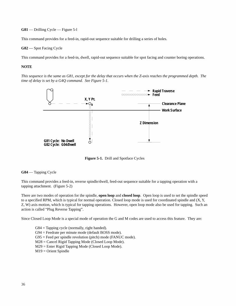
G81— Drilling Cycle — Figure 5-l
This command provides for a feed-in, rapid-out sequence suitable for drilling a series of holes.
G82— Spot Facing Cycle
This command provides for a feed-in, dwell, rapid-out sequence suitable for spot facing and counter boring operations.
NOTE
This sequence is the same as G81, except for the delay that occurs when the Z-axis reaches the programmed depth. Thetime of delay is set by a G4Q command. See Figure 5-1.
Figure 5-1. Drill and Spotface Cycles
G84— Tapping Cycle
This command provides a feed-in, reverse spindle/dwell, feed-out sequence suitable for a tapping operation with atapping attachment. (Figure 5-2)
There are two modes of operation for the spindle,open loopand closed loop. Open loop is used to set the spindle speedto a specified RPM, which is typical for normal operation. Closed loop mode is used for coordinated spindle and (X, Y,Z, W) axis motion, which is typical for tapping operations. However, open loop mode also be used for tapping. Such anaction is called “Plug Reverse Tapping”.
Since Closed Loop Mode is a special mode of operation the G and M codes are used to access this feature. They are:
G84 = Tapping cycle (normally, right handed).G94 = Feedrate per minute mode (default BOSS mode).G95 = Feed per spindle revolution (pitch) mode (FANUC mode).M28 = Cancel Rigid Tapping Mode (Closed Loop Mode).M29 = Enter Rigid Tapping Mode (Closed Loop Mode).M19 = Orient Spindle
X, Y Pt.
G81 Cycle: No DwellG82 Cycle: G04/Dwell
Rapid TraverseFeed
Clearance Plane
Work Surface
Z Dimension
36

When performing a rigid tap (closed loop mode) operation, the user’s part program provides the following information:
1. Spindle Speed in RPM (+/–)2. M29 to specify Closed Loop mode, othewise plug reverse tapping mode is used.3. Desired Z Axis travel distance (inch or metric).4. One of the following:
a. Axis feedrate (inch or mm/minute). (BOSS mode)b. Pitch = Z Axis travel per spindle rev. (FANUC mode)
Set with an “F” word address in either inches or millimeters per spindle rev.
The G95 mode (feedrate per spindle rev) may be used for any linear or circular move in addition to the tapping cycle,The G95 provides an alternate means of specifying feedrates. Note that the G95 works only with desired spindle speeds,it does not self adjust if the spindle speed varies due to load or operator actions.
Example #1:
N10S1000M3 ; Turn on spindle and set spindle speedN20G84X9.Y6.Z1.F20. ; Do plug reverse tapping
Example #2:
N10S1000M3 ; Turn on spindle and set spindle speedN20M29 ; Set Rigid Tapping ModeN30G84X9.Y6.Z1.F20. ; Do Canned Cycle for tappingN40M28 ; Cancel Rigid Tapping Mode
Example #3:
N10S1000M3 ; Turn on spindle and set spindle speedN20G95M29 ; Set Rigid tapping mode and Fanuc ModeN30G84X9.Y6.Z1.F.1 ; Do Tapping at .1 inches per revolution
For Plug Reverse Tapping, a chart of feed and speed values for tapping various pitches is given in Figure 5-3. Feeds andspeeds can be selected from this chart to program the desired thread pitch. Use of the designated speed minimizes theamount of tap holder compensation required.
Figure 5-2.Tap Cycle
X, Y Pt.
G04/Dwell
Rapid TraverseFeed
Clearance Plane
Work Surface
Z Dimension
SpindleForward
SpindleReverse
37

Figure 5-3. Feeds and Speeds for Tapping
The external device required for performing tapping operations is a special tapping tool holder with built in axial floatallowance. The recommended axial float in this holder is 3/8’ tension, 3/8” compression, which compensates for anyspindle speed/Z-axis feedrate deviation from the actual tap lead.
NOTES
1. Approximate dwell time in seconds for reversing are as follows:
200 rpm .30300 rpm .35400 rpm .50500 rpm .63
This can be programmed using either a G4Q__ command or a Q word within the drill cycle command.
For example, G84Q.35X 1.0Z.5F20. 0.
2. Try to use the lowest speed in either range and adjust the feedrate accordingly.
56 48 44 40 36 32 28 24 20
2 4 6 8 10 12 14 16 18 20 22 24
18
16
14
13
1211.5
400
300
200
100
Spin
dle
Spee
d, R
PM
Feedrate, IPM
Threads Per Inch
38

G85— Boring Cycle
This command provides a feed-in, feed-out sequence suitable for boring or reaming operations.
G86— Boring Cycle — Figure 5-4
This command provides a feed-in, spindle stop to wait for operator CONTINUE command, then rapid-out. The axesthen rapid traverse to the next hole, if programmed, and wait for the operator to restart the spindle before feeding in.
The stop at the bottom of the hole enables the operator to orient the spindle if required.
G89— Boring Cycle
This command provides a feed-in, dwell, feed-out sequence suitable for boring. The time of delay is previously set byG4Q__ command.
Deep Hole Drilling Cycles
The format for the deep hole cycles is:
G83(G87)X__Y__Z__Z__Z__F__G83(G87)A__Z__Z__Z__F__ (polar)
Where Z__Z__Z__ is the total Z depth, the first peck increment and subsequent peck increments.
NOTE
If the value for subsequent peck increments is omitted, the first value is used for all peck distances.
The Z-axis deep hole canned cycles comprise a sequence of the following operations:
Operation [l] Position X and Y axesOperation [2] Feed down 1st peck incrementOperation [3] Rapid traverse outOperation [4] Rapid traverse back in to previous peck depth. . . [3], [4], [5] are repeated until the total Z depth is reached .Operation [6] Retract to initial Z position.
Figure 5-4. Boring Cycle with Spindle Stop (G86)
X, Y Pt.
Program StopSpindle Stop
Rapid TraverseFeed
Clearance Plane
Work Surface
Z Dimension
Operator "Continue"
Operator "Spindle Start"
39

Figure 5-5. Deep Hole Drilling Cycle
Figure 5-6. Chip Break Deep Hole Drilling Cycle
G83— Deep Hole Drilling Cycle — Figure 5-5
This command provides a deep hole drilling cycle as described earlier in this section. After each peck increment, the Z-axis retracts back to the initial Z position.
G87— Chip Break Deep Hole Drilling Cycle
This command provides a chip break drilling cycle similar to the operation described previously. After each peckincrement, the Z-axis retracts .01” and then rapid traverse back to the previous depth, Figure 5-6. The purpose of theG87 cycle is to break the chip rather than to withdraw the tool entirely from the workpiece as in a G83 cycle.
Example:N1G0G90X0Y0T1M6N5X1.Y5Z.05; Position for first hole.N10G81Z1.1F80.; Set the drill cycleN15X 1.: Drill first holeN20X.5Y1.; Drill second holeN25G0X2.Z - .45; Rapid to X position third hole.N30G81Z.6F80.; Set up drill cycleN35Y1 .; Drill third holeN40X2.5Y.5; Drill fourth holeN45G0X0Y0M2; End of program
X, Y Pt.
Rapid TraverseFeed
Clearance Plane
Work Surface
Z Dimension
1st Peck
2nd Peck
3rd Peck
X, Y Pt.
Rapid TraverseFeed
Clearance Plane
Work Surface
Z Dimension
1st Peck
2nd Peck
3rd Peck
40

MULTI-HOLE Z-AXIS CYCLES
These cycles drill bore or tap the hole patterns described in Chapter 5.
Row Drilling Bolt Circles — Incremental Hole to Hole Distance
This command provides means for drilling a row of holes along the X or Y-axis or a bolt circle given the total distancefrom the first hole to the last hole and the incremental distance between holes. The format of this command is:
G81(G82....)X__X__Z__F__; X-axis rowG81(G82....)Y__Y__Z__F__; Y-axis rowG81(G82....)A__A__Z__F__; Bolt circle
Where X__X__, Y__Y__, A__A__ is the total hole distance, then the incremental hole distance. Z__F__ are the basicZ-axis cycle parameters described in Chapter 5 (Z__Z__Z__F__) are for deep hole drilling.
Figure 5-7. Row of Holes Along X-Axis
Program either (A), (B) or (C) below for Figure 5-7:
(A) Abs: G90G87X1.X.25Z1.0Z.25Z.15F8.0;(B) Incr: G91G87X-.75X.25Z1.0Z.25Z.15F8.0;(C) Abs: G90G87U-.75X.25Z1Z.25Z.15F8.0;
NOTES
1. It is assumed for these cycles, the programmer positions the axes over the first hole.
2. This format is for rows parallel to the X-axis or parallel to the Y-axis. However, these rows may be rotated using thetransformation command.
3. The total distance may be either absolute or incremental (U and V input are also allowed). The incrementaldistance for X and Y rows is an unsigned value. The incremental distance for bolt circles is a signed valuedependent upon the angular direction desired.
4. The last hole increment is either the value input or the remaining distance, whichever is less.
1"25
Typ.
OriginXO, YO
X 1.75
Start
41
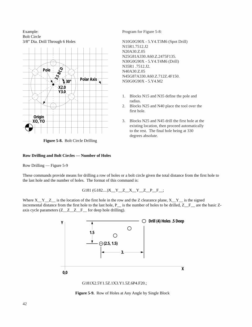
Example:Bolt Circle3/8” Dia. Drill Through 6 Holes
Figure 5-8. Bolt Circle Drilling
Row Drilling and Bolt Circles — Number of Holes
Row Drilling — Figure 5-9
These commands provide means for drilling a row of holes or a bolt circle given the total distance from the first hole tothe last hole and the number of holes. The format of this command is:
G181 (G182....)X__Y__Z__X__Y__Z__P__F__;
Where X__Y__Z__ is the location of the first hole in the row and the Z clearance plane, X__Y__ is the signedincremental distance from the first hole to the last hole, P__ is the number of holes to be drilled, Z__F__ are the basic Z-axis cycle parameters (Z__Z__Z__F__ for deep hole drilling).
G181X2.5Y1.5Z.1X3.Y1.5Z.6P4.F20.;
Figure 5-9. Row of Holes at Any Angle by Single Block
Y
X0,0
1.5
(2.5, 1.5)
3.
Drill (4) Holes .5 Deep
42
Program for Figure 5-8:
N10G0G90X - 5.Y4.T3M6 (Spot Drill)N15R1.7512.J2N20A30.Z.05N25G81A330.A60.Z.2475F135.N30G0G90X - 5.Y4.T4M6 (Drill)N35R1 .7512.J2.N40A30.Z.05N45G87A330.A60.Z.712Z.4F150.N50G0G90X - 5.Y4.M2
1. Blocks N15 and N35 define the pole andradius.
2. Blocks N25 and N40 place the tool over thefirst hole.
3. Blocks N25 and N45 drill the first hole at theexisting location, then proceed automaticallyto the rest. The final hole being at 330degrees absolute.
OriginXO, YO
X2.0Y3.0
30° Polar Axis
Pole
3.5
BCD

NOTES
1. This command automatically positions the axes over the first hole with a rapid traverse move.
2. Rows need not be parallel to the X or Y axis.
3. P, the number of holes, must be input with a decimal point.
Bolt Circles — Figure 5-10
The format of the bolt circle command is:
G181(G182...)A__Z__A__Z__P__F__;
Where A__Z__ is the location of the first hole in the bolt circle and the Z clearance plane, A__ is the signed incrementaldistance from the first hole to the last hole, P__ is the number of holes to be drilled, Z__F__ are the basic Z cycleparameters.
NOTE
R, I, and J data can be optionally included in this command.
This example causes the same spot drilling sequence as the blocks N15, N20, N25 in the example in Figure 5-8.
G181R1.7512.J3.A30.Z.05A300.Z.2475P6.F13.5;
Figure 5-10. Bolt Hole Circle Drilled by Single Block
OriginXO, YO
X2.0Y3.0
30° Polar Axis
Pole
3.5
BCD
43

Frame Drilling — Number of Holes — Figure 5-11
This command provides means for drilling a row of X and Y holes along the perimeter of a rectangular shape. Theformat of this command is:
G191(G192...)X__Y__Z__X__Y__Z__P__P__F__;
Where X__Y__Z__ is the location of the first corner hole and the Z clearance plane, X__Y__ are the signed valuesdefining the incremental distance from the first hole to the last hole along the X and Y axes, P__P__ are the number ofholes along the X and Y axis, and Z__F__ are the basic Z cycle parameters.
NOTE
The minimum value for P is 2.
G191X2.5Y2.Z.05X3.Y1.5Z.55P7.P4.F20.;
Figure 5-11. Rectangular Hole Pattern
Y
X0,0
3.
1.5
Drill (18) Holes .5 Deep
(2.5, 2.)
44

CHAPTER 6CANNED MILLING CYCLES
OVERVIEW
These functions enable machining frequently used shapes with one part program block. The following mill cycles areavailable:
G170: Outside Frame MillG171: Inside Frame MillG172: Pocket Frame MillG173: Outside Face MillG174: Inside Face MillG175: Outside Circle MillG176: Inside Circle MillG177: Pocket Circle MillG179: Slot Mill
The parameters for these cycles are shown in Table 6-1.
NOTES
1. The mill cycles in Table 6-1 are cutter diameter compensated using the cutter diameter for the tool currently beingused.
2. The mill cycles include an approach and departure tangential to the part work surface, a Z-axis step capability fordeep cuts and roughing and finishing cuts.
3. Length, width, fillet radius, step depth, step over, clearance, finish allowance are unsigned values.
4. Words may be addressed in any sequence except that words addressed by the same alphabetic character must be inthe order shown.
5. All cycles except the G 179 slot cycle may be transformed using rotation.
6. All parameters except step depth, finish feed and plunge feed must be entered even if they are 0. If finish feed isomitted, it defaults to the mill feedrate. If plunge feed is omitted, it defaults to 50% of the mill feedrate.
7. The Z start point must be at a clearance point above the work surface. Z cannot be at machine 0. It must be aminimum of .050” below Z home.
8. The dimension to the X, Y center point and the Z clearance plane may be incremental or absolute. All otherdimensions are incremental as noted. The G 179 slot mill cycle sets the control in absolute.
9. Variables may be substituted for canned cycle parameters. The variable to be used must not be in the parametertable (see Table 10-1).
10. In G170-G179 cycles, the default values for fillet radius, Z depth and Z step are set to 0.
11. G170-G179 mill cycles end up at the input center point.
12. Milling cycles end execution at the center of the shape (X and Y center point defined in cycle) with the Z-axis at theZ clearance plane.
13. A G 179 cycle puts the system in absolute programming mode (G90) after execution. If the incrementalprogramming mode (G91) is desired, it is necessary to program G91 after a G179 cycle.
45

Table 6-1. Parameters for Mill Cycles
170,171 172 173,174 175,176 177 179
Center Point X X X X X XCenter Point Y Y Y Y Y YStart Point Z Z Z Z Z ZLength X X X X PWidth Y Y Y Y P-DiaFillet Radius R RRadius R RAngle of Rotation from X+ Axis PFull Depth Z Z Z Z Z ZStep Depth Z Z Z Z Z ZStep Over, Overlap P P PClearance P P P P PMill Feed F F F F F FFinish Allowance P P P PFinish Feed F F F FPlunge Feed F F F F F F
OUTSIDE/INSIDE FRAME MILL — Figures 6-1 and 6-2
These cycles mill the outside or the inside of a rectangular shape. The format of this command is:
G170(G171)X__Y__Z__X__Y__R__Z__Z__P__F__P__F__F__;
Where the first X__Y__ set is the frame center point the first Z value Z__ is the clearance plane, the second X__Y__ setis the unsigned length and width, R__ is the fillet radius, the second Z__ is the full depth and the third is the step depth.The first P__ is the initial entry clearance and the second P__ finish allowance. F__F__F__ is the mill feed, the finishfeed and the plunge feed respectively.
NOTE
The sum of the entry clearance and the finish allowance must be smaller than the X length and Y width.
46

Example:T1//0.; Tool Diameter = 0N10G170X3.Y4.Z - 4.X2.Y1 .5R.25Z.52P.25F20.P.1
Figure 6-1. Outside Frame Mill
Example:T1//0.; Tool Diameter = 0N20G171X3.Y4.Z - 4.X2.Y1 .5R.25Z.52P.25F20.P.1
Figure 6-2. Inside Frame Mill
InitialXZ Move
P, Clearance
Z Depth
X Length
Y Width
R, Fillet
System CalculatedStart Point
Z Clearance PlaneTool End Point
P, Finish Allowance
X, Y Center PointTool End Point
X, Y Center PointTool End Point
P, Clearance
P, Finish Allowance
Y WidthR, Fillet
System CalculatedStart Point
Z Clearance PlaneTool End Point
InitialXZ Move Z Depth
X Length
47

NOTE
Overlap is the amount of overcut caused by two consecutive passes of the cutting tool (Figure 6-3). Thus, the centerline to center line tool move is equal to the tool diameter minus the overlap. For example, if the tool diameter = .4 andthe input overlap value = .25, then the center line to center line move = .15.
See the examples in Figures 6-5 and 6-6.
Figure 6-3. Definition of Overlap
Example:T1//.4; Tool Diameter = .4N30G172X3.Y4.Z - 4.X2.Y1 .5R.25Z.52P.2P.25F20.P.05
Figure 6-4. Pocket Frame Mill
POCKET FRAME MILL — Figure 6-4
The pocket frame mill is a combination of an inside pocket mill routine and the inside frame mill routine. The formatfor this command is:
G172X__Y__Z__X__Y__R__Z__Z__P__P__F__P__F__F__;
X Length
Y Width
System CalculatedStart Point forFinish Pass
P, Clearance
P, Finish Allowance
X, Y Center PointTool End Point
System CalculatedStart Point
R, Fillet
InitialY Z Move
Z Depth Z Clearance PlaneTool End Point
ToolDiameter = .4
Center to Center Move = .15Overcut = .25
48

Where X__Y__ is the pocket center point. Z__ is the clearance plane, X__Y__ is the unsigned length and width, R__ isthe fillet radius, Z__Z__ is the full depth and step depth, P__P__P__ is the step over, the clearance dimension for boththe plunge to the center of the pocket and the final inside frame pass, and the finish allowance, F__F__F__ is the millfeed, the finish feed and the plunge feed.
NOTE
The stepover on both the X and Y axes for the final pocket frame mill cut is equal to the input stepover value. If thepocket is not square, the stepover moves on the smaller of the axes to be moved is less than the input stepover value.
OUTSIDE/INSIDE FACE MILL
These cycles use zigzag moves to face the surface of a rectangular shape (G173) or to rough cut the material inside theboundary described by a rectangular shape (G174). The format for this command is:
G173(G174)X__Y__Z__X__Y__Z__Z__P__P__F__F__;
Where X__Y__ is the center point of the rectangle to be faced, Z__ is the clearance plane, X__Y__ is the unsignedlength and width, P__P__ is the overlap and the clearance for the plunge cut, F__F__ is the milling feedrate and theplunge feed.
Example:T1//.4; Tool Diameter = .4N40G173X3.Y4.Z - 4.X2.Y1 .5Z.52P.25P.2F20.
X Total = X Length + Tool diameter + (2* Overlap)Y Total = Y Width + (2* Overlap) - Tool Diameter
Figure 6-5. Outside Face Mill
X Move
Y Move
P, Overlap
X LengthP, Overlap
Y Width
P, Clearance
X = Clearance
InitialXZ Move
X, Y Centerpoint
49

Example:T1//.4; Tool Diameter = .4N50G174X3.Y4.Z - 4.X2.Y1 .5Z.52P.25P.2F20.
X Total = X Length - (Tool diameter + (2* Overlap))Y Total = Y Length - (Tool diameter + (2* Overlap))
Figure 6-6. Inside Face Mill (Zig-Zag Pocket Mill)
OUTSIDE/INSIDE CIRCLE MILL
These cycles mill around the outside of a circular shape (G175) or the inside of a circular shape (G176). The format forthis command is:
G175(G176)X__Y__Z__R__Z__Z__P__F__P__F__F__;
Where X__Y__ is the center point of the circle, Z__ is the clearance point, R__ is the circle radius, Z__Z__ is the fulldepth and the step depth, P__P__ is the tool entry clearance and the finish allowance, F__F__F__ is the mill feed, thefinish feed and the plunge feed.
NOTE
The sum of the entry clearance and the finish allowance must be smaller than the circle radius.
Example:T1//0; N60G175X3.Y4.Z - 4.R1.Z.52P.25F20.P1.
P, ClearanceInitial
XZ MoveX = Clearance
Tool End Point
System CalculatedStart Point
Y Width
X Length
X TotalP, Overlap
P, Overlap
Y Total
50

Figure 6-7. Outside Circle Mill
Example:T1//0; N70G176X3.Y4.Z - 4.R1.Z.5P.25F20.P1.
Figure 6-8. Inside Circle Mill
X, Y Center PointTool End Point
Z Clearance PlaneTool End Point
Z Depth
R,Radius
System CalculatedStart Point
P, Clearance
X, Y Center PointTool End Point
P, Clearance
System CalculatedStart Point
Z Clearance PlaneTool End Point
Initial XZ MoveX = Clearance
Z Depth
P, Finish Allowance
R,Radius
51

POCKET CIRCLE MILL
The pocket circle mill is a combination of an inside spiral mill routine and an inside circle mill routine. The format forthis command is:
G177X__Y__Z__R__Z__Z__P__P__P__F__F__F__;
Where X__Y__ is the center point of the circle, Z__ is the clearance plane, R__ is the circle radius, Z__Z__ is the fulldepth and the step depth, P__P__P__ is the step over, the clearance dimension for both the plunge to the center and thefinish allowance.
G177X2.0Y0Z0R2.0Z.2Z.1P.4P.01P.01F20.F30.F30.
Figure 6-9. Pocket Circle Mill
SLOT MILL
This cycle mills a slot at any angle to the X-axis. The format for this command is:
G179X__Y__Z__P__P__P__Z__Z__F__F__;
Where X__Y__ is the center point of the arc boundary, and the point about which rotation is to take place, Z__ is theclearance plane, P__P__P__ is the out to out length of the slot, the slot diameter and the angular rotation from the X-axis, Z__Z__ is the full depth and step depth, F__F__ is the mill feed and the plunge feed.
NOTE
The Slot Mill command cannot be transformed by rotation (G73). If in incremental, the system is set to the absolutepositioning mode G90 after execution of a G179 cycle. The next block must contain a G91 if incremental positioningmode is to be maintained. G179 cannot be programmed with polar coordinates.
R,Radius
P, Clearance
X, Y Center Point
P, FinishAllowance
Z Clearance PlaneTool End Point
Z Depth
Stepover
52

Example:T1//0; N80G179X3.Y4.Z - 4.P1.5P.5P30.Z.52F20.
Figure 6-10. Slot Mill at Any Angle to X-Axis
Example:T1//0; N90G179X3.Y4.Z - 4.P1.5P.5P0.Z.52F20.
Figure 6-11. Slot Mill Parallel to X-Axis
G77, G78, G79 — Special Mill Cycles
The control has three special mill cycles that reduce programming time and tape length for certain operations. Thesecycles require the tool to be at the start position and to depth before they are programmed.
G77 — Facing Cycle. The format is:
G77X__Y__Y__F__
X__= signed Incremental distance to be milled along the X-axis
Y__= Incremental distance to be milled along the Y-axis
Y__= Y-axis step over valueF__= Feed rate value
G77X7.2Y2.85Y.95F100 face mills a 6.0” x 3.75” block as shown in Figure 6-12 with a 1 “ dia. end mill.
The G77 block must be followed by Absolute Coordinate data.
Z Depth
Z Clearance PlaneTool End Point
P, Length
InitialXZ Move
P, Diameter
Y
X
X, Y Center Point of Rotation,Tool Start and End Point
P, Angular Rotation PromX- Axis
53

From the bottom left hand corner of the area to be milled, the first move is an + X-axis move equal to the X-axis inputvalue. The cutter then moves +Y the stepover distance. The cutter then makes a - X move, followed by a + Y stepovermove. This zigzag pattern continues until the sum of the stepover moves is equal to the Y input distance. The cutterthen makes the last X-axis move.
NOTE
1. Tool must be at start position and to depth before initiating cycle.
2. Cutter Diameter Compensation cannot be used.
3. Next move after G77 must be absolute.
Figure 6-12. Facing Mill
G78 — Pocket Milling Cycle. The format of this cycle is:
G78X__X__X__Y__Y__F__F__
Wherein the order stated in the format:
X__= the distance from the center of the pocket to the wall along the X-axis less thecutter radius.
X__= the X-axis stepover value.
X__= the optional distance for the final boundary cut. If set to zero, then the finalboundary cut is set at the default value of .020n.
Y__= the distance from the center of the pocket to the wall along the Y-axis less thecutter radius.
Y__= the Y-axis stepover value. If not programmed, the X and Y stepover distanceis equal to the X stepover value.
F__= the feedrate value for all the roughing passes.
F__= the optional feedrate for the boundary cut. If zero, the boundary cut has afeedrate of 1.5 times the roughing feedrate.
0.0
X - .6Y.45
54

For example: Mill the pocket shown using a .5” diameter cutter. For the most efficient result, using X.25” stepovermaximum value, the minor axis (Y) stepover value should be .107”; calculated according to the following:
.25 “([n4i]n 1 ) = .25 (.7511.75) = .107Program: G78X1.75X.25Y.75Y.107F100
Figure 6-13. Pocket Mill
From the center of the pocket, the first move is an X and Y-axis stepover. The center then moves - X, - Y, +X, +Y at avalue equal to twice the accumulated stepover distance. The cutter then makes another XY stepover move. Thiscontinues until the cutter is within .020” of the pocket wall. Note: Once an axis reaches .020” from the pocket wall, itno longer is incremented during the stepover move. The last stepover move is .020” in both X and Y followed by arectangular cut at a feedrate 50% higher than the input feedrate. The cutter then feeds to the center of the pocket to endthe cycle.
Alternatively Program:G78X1.75X.25X.01Y.75Y.107F10.0F12.0
The roughing passes proceed as before at 10 ipm and continue until the cutter is within .010” of the pocket wall. Thefinishing +X+Y departures then takes place and the .01” perimeter pass is made at 12 ipm. The tool returns to the centerof the pocket at 12 ipm.
G79 — Internal Circular Milling Cycle
This cycle, consisting of only one block, may be useful in machining circular pockets, counterboring large diameters,rough hole boring, etc. It is the programmer’s responsibility to be at the center of the hole and to depth before callingthe G79 cycle.
The format required is as follows:G79 J__F__
Where the J__ is the radius of the hole to be machined minus the cutter radius, i.e.,
J = (Part Radius) - (Cutter Radius)
1.0
2.0
55

Figure 6-14. Bore Milling Cycle
NOTE
The accompanying sketch (Figure 6-14) shows the actual cutterpath for the G79 cycle. Note that the entering andleaving tangent small circle’s radius is J/2.
Program #1 — Programmed for.5 Dia. End Mill(J = (.375) - (.25) = .125)
N1G0G90X - 3.Y3.T1 M6N5X0Y0Z.05N10G1Z - .1 F5.0N15G79J.125F10.0N20G0X - 3.Y3.M2
Figure 6-15. Example of Bore Milling
It is important to note that G79 cannot be used with Cutter Diameter Compensation; however, the same cutter path maybe programmed using G75 Multi-Quadrant Circular when cutter compensation is required. Program #2 illustrates thismethod using the same cutter path shown in the sketch of Program #1.
NOTE
G77, G78, G79 are older canned cycles and do not have the flexibility of the G170 series. For this reason, it isrecommended that the G170 series be used in all new programs.
.75 Dia.-.1" Deep
XO, YO
JJ/2
56
Program #2N1G0G90X-3.Y3.T1M6.N5G75N10X0Y0Z.05N15G1Z-.1F5.0N20X.0625Y.0625F1 0.0N25G3X0Y.125I0J.0625N30G3X0Y.125I0J0N35G3X-.0625Y.062510J.0625N40G1X0Y0N45G0X-3.Y3.M2

CHAPTER 7CUTTER DIAMETER COMPENSATION
OVERVIEW
In order to machine the workpiece shown in Figure 7-1, when not in cutter compensation, the programmer must allowfor the cutter diameter and calculate the offset path the tool must make to generate the desired shape. The cutterdiameter compensation function provides means in the control for computing the offset path. This feature can be usedthe following ways:
1. The workpiece shape can be programmed directly by the programmer. The cutter diameter to be used canbe measured and in the setup mode can be entered into the control. The control automatically computesthe offset tool path to generate the workpiece surface.
2. The input data to the control may already be the offset cutter path. In this case, cutter diametercompensation may be used to compensate for the difference between the cutter diameter value assumed bythe part programmer and the actual value. This cutter diameter compensation enables a given part programto be executed with cutters of different diameters and still produce the same part.
3. Two or more different diameter compensation values can be programmed for the same tool to take care ofroughing, semi-finish and finish passes.
4. During normal operation, one block of program information is read into the buffer register while theprevious block is being performed. This is to avoid interruptions between blocks during transfer of data tothe active registers. During tool diameter compensation, two data blocks are buffered to look ahead in theprogram in order to provide new coordinates internally offset by the compensation amount.
CUTTER DIAMETER DATA ENTRY
The following methods can be used for setting the cutter diameter value into the control:
1. Enter cutter diameter data via the operator panel.
Use the TOOL key to scroll through the tool data table, from tool #1 through tool #24. ENTER loads the numeric datakeyed in and displayed on the screen (either T, TLO or DIA) into the system.
2. Enter cutter diameter data via part program text. The format is:
T__/__/__ or T__D__;
Where T__ is the tool number and /__/__ is the TLO value and the DIA value or D__ is the diameter value.
57

Figure 7-1. Tool Path Offset by Cutter Radius
3. Maximum cutter compensation value is:
+3.2768 inches(+83.321 mm)
Example:
T5//-.5; For tool 5, DIA = -.5T4/.75/.2; For tool 4, TLO = .75, DIA = .2T5D - .5 For tool 5, DIA = - .5
If the program input data is already the offset cutter path, the input value is the actual cutter diameter minus theprogrammed cutter diameter. A positive cutter diameter value designates an oversize cutter, a negative cutter diametervalue designates an undersized cutter.
The cutter diameter compensation value is activated when a G41 or G42 command is read. The tool number that selectsthe compensation value must be entered prior to the initiation of cutter compensation.
PLANE SELECTION
Compensation is only active in the XY plane. The system must be in the G17 mode.
Rules for Z moves with cutter compensation turned on are as follows:
1. A Z move may be programmed on the same block as a linear X, Y move. The Z move is not compensated.
2. A Z move may be programmed without a linear X, Y move. If multiple Z only moves are used, they mustbe separated by at least one block containing an X and/or Y move.
OffsetTool Path Tool
Workpiece
58

CUTTER DIAMETER COMPENSATION COMMANDS
The following commands are:G40 — Cutter compensation offG41 — Cutter compensation on, tool left of partG42 — Cutter compensation on, tool right of part
NOTE
Even though G41 or G42 is programmed, cutter compensation is not active unless the current tool diameter is a valueother than zero.
The system must be in either the rapid traverse (G0) or linear (G1) mode when cutter compensation is turned on. Toolleft or tool right with respect to the part is determined by looking from behind the tool in the direction of motion. SeeFigure 7-2.
ENTRY INTO CUTTER DIAMETER COMPENSATION
The data block containing the G41 or G42 move is non-compensated. The tool moves directly to this point. Thefollowing sequence of command must occur to turn on cutter compensation:
G0(G1)G41(G42)X__Y__; Turn on PointG0(G1)X__Y__; Approach Point(G1,G2,G3)X__Y__....; 1st Compensated Path
The approach point must be defined by a linear move. Before the approach move is made, the next input block is readcontaining the definition of the first line or circle to be compensated. The approach move is then made normal to thefirst line or circle to be compensated through the approach point at a distance equal to the stored tool radius. See Figure7-3.
BLOCK INTERACTIONS
Cutter compensation handles the following types of interactions:
MoveTo Be Next Inside Outside
Compensated Move (See Figure) (See Figure)
Line Line 7-5 7-9Line Circle 7-6 7-10Circle Line 7-7 7-11Circle Circle 7-8 7-12
Special conditions in Cutter Compensation are illustrated in Figures 7-13 and 7-14.
The calculation of offset path for a particular move also depends on what the next move is, cutter compensationtherefore, provides “look-ahead” ability. During cutter compensation two data blocks are read in advance normally.Thus, inside the CNC, there are three blocks, the block under execution, and the next two blocks which are used tocalculate the next offset path.
59

With standard right hand milling cutters:G41 — (Climb Milling)G42 — (Conventional Milling)
Figure 7-2. Tool Left; Tool Right
The angle of intersection created by two blocks of move commands as measured on the workpiece side create an“inside-corner” when the angle is over 180 degrees, an “outside-corner” when the angle is less than 180 degrees or a“tangency” when the angle is equal to 180 degrees. See Figure 7-4.
Note that if an outside corner occurs and G49 is active, an arc is automatically blended through the point of intersectiontangent to the two programmed paths.
N10G0G41X1.Y2. N10G0G41X1.Y2.N20G1X4.Y0.F20. N20G1X4.Y0.F20.N30G1X8.Y3. N30G2X6.5Y1.5I6.5J-1.
Figure 7-3. Entry Into Cutter Compensation
Turn OnPt. (1,2)
ToolRadius
ApproachMove
ApproachPt. (4,0)
(8.3)
FirstCompensated
Circle
ToolRadius
FirstCompensated
Circle
(6.5,1.5)
Turn OnPt. (1,2)
ApproachMove
ApproachPt. (4,0)
Arc Center(6.5,-1.)
(G41)
(G42)
60
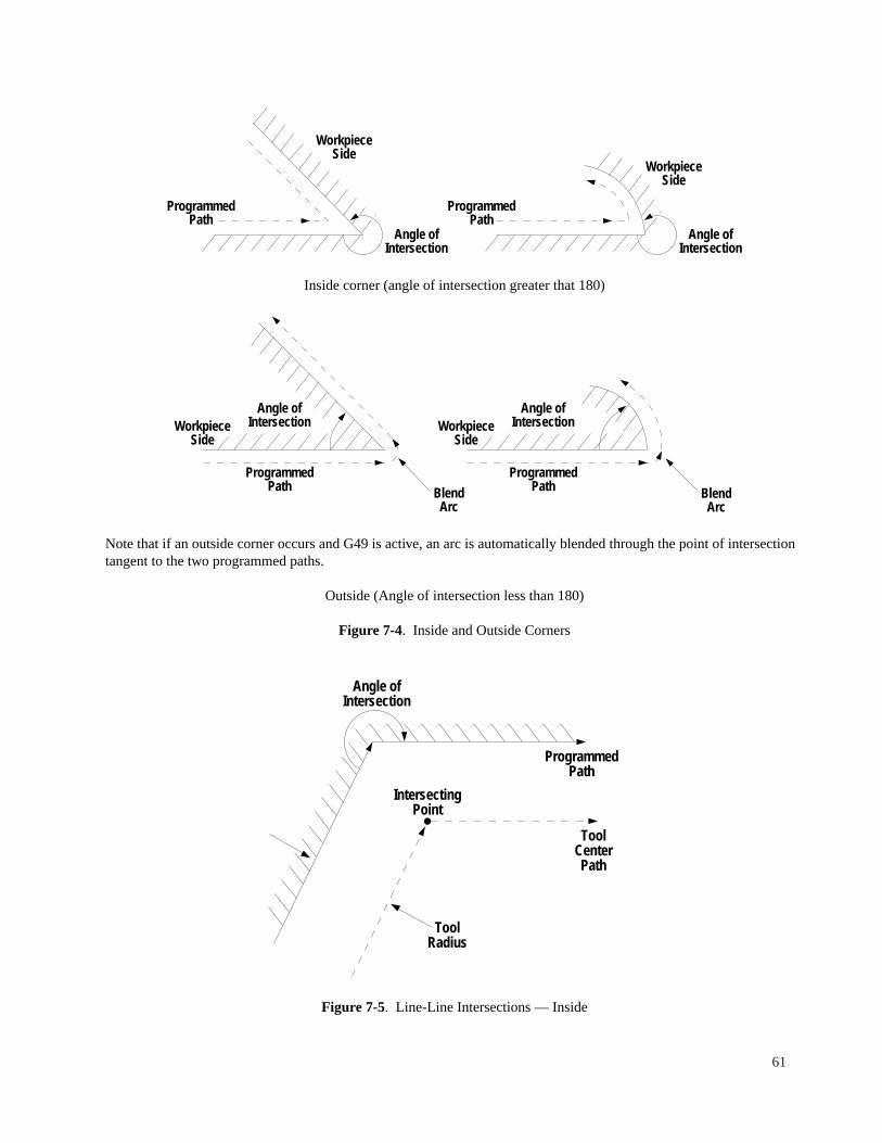
Inside corner (angle of intersection greater that 180)
Note that if an outside corner occurs and G49 is active, an arc is automatically blended through the point of intersectiontangent to the two programmed paths.
Outside (Angle of intersection less than 180)
Figure 7-4. Inside and Outside Corners
Figure 7-5. Line-Line Intersections — Inside
Angle ofIntersection
ToolRadius
ProgrammedPath
ToolCenterPath
IntersectingPoint
ProgrammedPath
WorkpieceSide
Angle ofIntersection
BlendArc
ProgrammedPath
WorkpieceSide
Angle ofIntersection
BlendArc
ProgrammedPath
WorkpieceSide
ProgrammedPath
WorkpieceSide
Angle ofIntersection
Angle ofIntersection
61
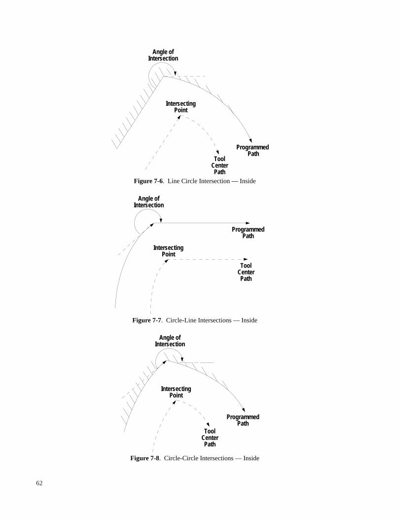
Figure 7-6. Line Circle Intersection — Inside
Figure 7-7. Circle-Line Intersections — Inside
Figure 7-8. Circle-Circle Intersections — Inside
ToolCenterPath
ProgrammedPath
IntersectingPoint
Angle ofIntersection
ToolCenterPath
ProgrammedPath
Angle ofIntersection
IntersectingPoint
ToolCenterPath
Programmed Path
IntersectingPoint
Angle ofIntersection
62

Figure 7-9. Line-Line Intersections — Outside
Figure 7-10. Line-Circle Intersections — Outside
Angle ofIntersection
ToolCenterPath
BlendArc
ProgrammedPath
ToolCenterPath
ProgrammedPath
Angle ofIntersection
BlendArc
63
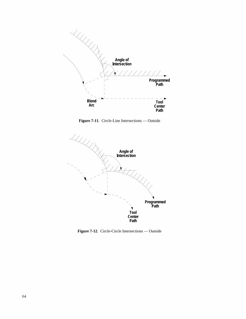
Figure 7-11. Circle-Line Intersections — Outside
Figure 7-12. Circle-Circle Intersections — Outside
ToolCenterPath
Angle ofIntersection
ProgrammedPath
Angle ofIntersection
BlendArc
ToolCenterPath
ProgrammedPath
64

If the part program calls for cutting a concave or notch-like feature in the part, the cutter diameter must be no greaterthan the diameter or width of the feature to be cut. If the cutter diameter is larger than the width of the feature to be cut,gouging occurs.
Figure 7-13. Oversize Cutter in a Notch
If the part program calls for making a small step less than the cutter radius, gouging occurs.
Example A Example B
T1 T1G0G41X-.2Y.6Z-.1 G0G41X-.2Y.6Z-.1G1X0Y0F20. G1G48X0Y0F20.X1.0 X1.0Y-.25 Y-.25X2.0 X2.0G40X2.2Y.6 G40X2.2Y.6
Figure 7-14. Step Smaller than Cutter Radius
Tool Center Path 1.0Dia. (Example A)
Tool Center Path .5Dia. (Example A)Tool Center Path .25Dia. (Example A)
Tool Path (Example B)
ProgrammedPath
.25
ToolCenter Path
.25 Dia.
ToolCenter Path
1.0 Dia.
ProgrammedPath
65
TIG0G41X-.4Y.8Z-.1G1X0Y0F20.X1.G3X1.4Y-.8I2.J0X1.8Y0I.8J0G1X2.8G40X3.2Y.8

EXIT FROM CUTTER DIAMETER COMPENSATION
Cutter compensation is turned off by a block containing a G40 command. The tool moves directly to this point. Thefollowing sequence of events must occur to turn off cutter compensation.
(G1,G2, G3) X__Y__....; Last Compensated PathG40X__Y__; Turn Off Point
The exit cutter compensation move is through the endpoint and normal to the last compensated path at a distance equalto the stored tool radius.
Figure 7-15. Exit From Cutter Compensation
1.5
XO, YO
1.5
XO, YO
XO, YO
R.75
1.5 Sq.
66
Tool .5 Dia.
N10G0G90X-1.Y1.T1M6N20G41Y0Z0N21G1X0Y0F20.N22X1.5N23Y-1.5N24X0N25Y.1N26G0G40X- 1.Y1.N30T2M6
N10G0G90X-1.75Y-1.T1M6N20G41Y0Z0N21G1X-.75F20.N22X0Y1.5N23X.75Y0N24X-.85N25G0G40X-1.75Y-1.N30T2M6
N10G0G90X-1.25Y1.25T1M6N20G41Z0N21G1X-.5Y.75F20.N22X0N23G2X0Y.7510J0N24G1X.75N25G0G40X-1.25Y1.25N30T2M6

FACTORS AFFECTING USE OF CUTTER COMPENSATION
1. The tool to part relationship (G41, G42) cannot be changed unless compensation is turned off (G40 mode).Also, the amount of compensation cannot be changed while in G41 or G42.
2. In compensating for cutter diameter, a G45 command can be used to adjust feedrates in accordance withthe difference in radius between the part surface and the tool path. The actual feedrate = input feedratemultiplied by tool path radius/part radius. For outside circles, the feedrate is increased; for inside circles,the feedrate is decreased (refer to Chapter 8).
3. A data block without a tool movement cannot be commanded with compensation turned on.
4. With cutter compensation in effect, some dwell may occur for blocks that are executed in less than .25seconds.
5. Co-linear moves cannot be programmed.
6. The minimum number of part program blocks that can be used in compensation is 5. The first blockcontains a G41 or G42, the next three blocks are compensated data points, the fifth block contains a G40which turns compensation off.
7. Z-axis moves are not compensated. Multiple Z moves must be separated by at least one block containingan X and/or Y move.
8. M (Auxiliary function) codes cannot be used from the block after cutter compensation is turned on untilthe block after cutter compensation is turned off.
9. G99, deceleration override, is automatically generated when successive motion is tangential while cuttercompensation is active. Any G99’s input into the part program text are stripped out during cuttercompensation and inserted only when successive moves are tangential.
10. The value of the tool compensation used must be other than zero for cutter compensation to be active.
11. When corner-rounding is set to ON (G49), all adjacent non-tangent moves are connected automatically byan arc move. If corner rounding is set off (G48), adjacent moves are made as they are defined. See Figure7-14.
12. G49, corner rounding on, is the default condition of the system in the BOSS 8-10 operational mode. In theBOSS 4-7 compatibility mode, G48 (corner rounding off) is the default.
13. G48 and G49 may be used in G41 or G42 to switch from rounding on to rounding off.
67

68

CHAPTER 8FEED FUNCTION (F FUNCTIONS)
OVERVIEW
F codes consist of the address F followed by the numeric value of the desired feedrate. No sign of direction ( + or -) canexist in a feedrate word.
Programmed F-words express feedrate in inches per minute if G70 is active, and in millimeters per minute if G71 isactive. F-words are modal; that is, the active programmed feedrate remains active until the control executes another F-word.
RAPID TRAVERSE RATE
A G0 (rapid traverse) command is given to cause rapid motion between points. G0 overrides the set feedrate. However,if a subsequent G1, G2 or G3 block is programmed, the feedrate previously in effect is resumed. If the G0 data blockcontains X or Y and Z data and the Z move is below the current Z plane (quill down), the XY move occurs first, then theZ move. If the Z move is above the current Z plane (quill up), the Z move up occurs first, then the XY move. XYmotion is approximately linear at the rapid traverse rate within a tolerance band of .01 inch.
The rapid traverse rates are as follows:
XY Axis 472 ipm (12000mm/m)
In Block mode and in Setup, override can be applied to the rapid traverse rate using the feedrate override knob withoverride enabled.
CUTTING FEEDRATE
The following is the range of input feedrate commands:
G70 (Inch) .5 to 295.0 ipmG71 (Metric) 2. to 7500 mm/m
The feedrate is clamped to the upper limit value. The system maintains constant vector velocity in the feed range forboth 3-axis linear and 2-axis circular interpolation, regardless of the slope of cut.
NOTES
1. Feedrate (non-G0) moves are inhibited until the spindle has been turned ON.
2. Decimal point programming must be used for feedrates except if the system is in the BOSS 4-7 Compatibility mode.
3. Automatic acceleration occurs at the start of every move, deceleration at the end of every move.
4. A non-modal G99 code overrides deceleration in the block in which it is programmed.
5. A modal G9 code overrides deceleration in all blocks until G8 is programmed.
69

FEEDRATE OVERRIDE
The active feedrate can be increased or reduced using the FEEDRATE OVERRIDE key. When override is enabled (bypressing the OVERRIDE ENABLE key), the operator can vary the actual feedrate from 5 to 150% of the programmedfeedrate, by pressing the FEEDRATE OVERRIDE keys (the up and down arrow keys on the operator’s keyboard).
In AUTO RUN, the override keys do not affect the rapid traverse rate. The override control affects rapid traverse in theBLOCK mode.
NOTE
Feedrate override enable is turned off either manually or automatically by the next programmed tool change.
CONSTANT SURFACE FEED
A G45 command enables modifying the feedrate during cutter compensated circular moves to maintain constant surfacefeed. G45 is the default or reset condition.
A G44 command causes normal input feedrates.
When programming feedrates for circular cuts, the ratio of the cutter path radius to the part surface radius affects thecutting rate, since the vector velocity is that at the center of the cutter, not at the surface of the material. This means that,in order to maintain a constant chip load when machining the outside of an arc, the feedrate should be increased.
((PR+CR)/PR)*PF = MF
PR = Part RadiusCR = Cutter RadiusPF = Programmed FeedrateMF = Modified Feedrate
Referring Figure 8-1: Arc #1 (Block N11)Programmed Feedrate = 10 IPM
PR = 1.5 “ CR = .5”
1.5 + .5((1.5 + .5)/1.5)*(10) = 13.3 IPM
Therefore, to maintain constant surface feed, the feedrate should be increased to 13.3 IPM. Conversely when machiningthe inside of an arc, the feedrate should be decreased according to:
((PR - CR)/PR)*(PF) = MF
Refer to Figure 8-1: Arc #3 (Block N13) PR = 1.25” CR = .5 “
((1.25 - .5)/1.25)*(10) = 6 ipm; modified feed
Arc #4 (Block N14) PR = 8.5” CR = .5
((8.5 - .5)/8.5)*(10) = 9.4 IPM; modified feed
These modified feedrates occur automatically in the G45 mode.
70

;G41 ON, G45 ON, G74 ONN11G2G90G99X1.414Y2.I1.414J1.414F10.N12G99X3.414Y0I0J2.N13G3G99X4.164Y-.75I.75J0N14G99X9.82Y1.594I0J8.N15G1X11.82Y3.594
Figure 8-1. Example for Constant Chip Load
G94–– FEEDRATE PER MINUTE (MODAL)
The G94 is the default mode for all DX-32 machines. This command is used to reset the spindle to the feedrate perminute after a G95 has been programmed.
G95–– FEEDRATE PER SPINDLE REVOLUTION (MODAL)
The G95 mode provides an alternate means of specifying feedrates; inches (or millimeters) per spindle revolution. Thismode is typically used with the M29 rigid-tapping mode (Discovery Machines only). Note that G95 works only withdesired spindle speeds, it does not self-adjust if the spindle speed varies due to load or operator actions. The G95command remains active until a G94 is executed. See Chapter 5, Rigid Tapping, for an example of using the G95command.
G99 — DECELERATION OVERRIDE (NON-MODAL)
Automatic deceleration occurs at the end of every move. Deceleration and the end of a particular move may beeliminated by programming a G99 on that block. This provides a small transition between the end of the blockcontaining the G99 and the beginning of the next motion block. G99 should only be used in feedrate (G1, G2, G3) moveblocks when the change in direction between the blocks is not more than 20°. G99 should never be programmed on aline that uses either G0 or an M-code.
5.656
2
4
8.
PartSurface
2.
5
21.5 2.
1.414
Origin X = 0 Y = 0
1.414
.75 Rad
.586
1. Dia.Cutter
3
2.344
1
71

When cutter diameter compensation is active, G99’s input by the programmer are ignored by the system. G99s areautomatically inserted during cutter compensation when successive moves are tangent.
G9 — DECELERATION OVERRIDE (MODAL)
A G9 command has the same effect as a G99 placed in every block. The G9 eliminates deceleration at the end of eachblock that follows its initial entry until cancelled by G8.
NOTES
1. G9 must be turned off (with G8) before the execution of a rapid traverse (G0) block.
2. G9 is very effective with 2 or 3 dimensional DNC programs.
3. If the change in direction of the tool is too great, the axis drives will fail. Program G8 in any such problem area.
72

CHAPTER 9AUXILIARY MACHINE CONTROL FUNCTIONS
SPINDLE SPEED — S FUNCTION
The address S followed by a numeric value designates the spindle speed. The spindle moves to programmed speedbefore any feedrate motion on the block is entered. A rapid traverse may take place while the spindle is ramping tospeed. Spindle speeds in the part program are used only if the AUTO S option is on.
The operator may override the programmed spindle speed by using the speed increase/decrease keys on the front panel.
TOOL FUNCTION — T FUNCTION
The tool function consists of the address T followed by a two digit number ranging from 1 to 24. The tool word has thefollowing functions:
1. Store tool length offsets and diameter compensation. The format for this command is:
T__/__/__ or T__D__
Where the numeric value following the T address (T__) designates where in the tool offset table the subsequent datais to be stored, the numeric value after the first / code designates the tool length offset and the numeric value afterthe second / code designates the diameter offset. D can be used to enter the diameter offset.
Example:T1/1.1.5; Tool = 1, TLO = 1., DIA = .5T7//.375; TLO is unchanged, DIA=.375
2. Select the active tool number.
3. When a tool change command (M6, M26) is read by the control, the tool length offset for the active tool number isset into the Z move offset register. Refer to Chapter 4 for details on TLOs.
4. When a cutter compensation on command (G41, G42) is read by the control, the cutter diameter for the active toolnumber is set into the cutter compensation register and used for subsequent calculations.
Example:N100T2M26; Tool Change @ CLR PT, TOOL=2N204T7G41X0Y0; Use TOOL = 7 for DIA Compensation
Tool length compensation can be entered into the system using any of the following methods:
1. Tool key input2. Touch-off3. Inserting in a part program
The format is T__/__ where the tool number is designated and after the </> is the tool length offset unsigned value.
73

MISCELLANEOUS FUNCTION COMMANDS
Programmed miscellaneous function codes (M codes) initiate various machine tool functions and establish variouscontrol conditions. The following lists the miscellaneous function codes available:
M0 Program Stop (Non-Modal)M1 Optional Program Stop (Non-Modal)M2 End Of Program (Non-Modal), Rewind to Top of BufferM6 Tool Change (Non-Modal)M7 Coolant/ Mist (Modal)M8 Coolant/ Flood (Modal)M9 Coolant Off (Modal)M12 Enable Closed Loop Spindle Mode (unconditional) (Modal)M14 Reverse Spindle Direction (Modal)M15 Enable Open Loop Spindle Mode (Modal)M19 Orient Spindle (Non-Modal)M20 Program Stop, Goto Clear Pt (Non-Modal)M21 Optional Program Stop, Goto Clear Pt (Non-Modal)M22 End Of Program, Rewind to Top of Text Buffer, Goto Clear Pt (Non-Modal)M25 Quill Home (Non-Modal)M26 Tool Change, Goto Clear Pt (Non-Modal)M28 Cancel Rigid Tapping Mode (Modal)M29 Enable Rigid Tapping Mode (Modal)M51 Advance Index Table (Non-Modal)
NOTE Only one M code can be used in a part program block.
M0 — Program Stop
Spindle and coolant flow stop and program execution is halted. To continue operation, use the START/CONTINUE key.
NOTES
1. For M0 and M1, the quill remains at its last programmed position.
2. For all M codes, the system must be in the Rapid Traverse mode.
M1 — Optional Stop
This is the same an an M0 code, except it is only executed if the OPSTOP function has been selected. Otherwise, M1 isignored.
M2, M30 — Program Rewind
The spindle, coolant flow and program execution are halted. Before commanded XY motion occurs (if programmed),the quill is retracted to the up position. The program text pointer is reset.
NOTES
1. Program rewind resets the text pointer to the top of the text area.
2. The program rewind command resets the active preparatory function (G code) commands to initialized conditions.The following G codes are set:
G0, G17, G30, G40, G45, G70 or 71, G72, G75, G90, G96
Pressing START/CONTINUE repeats execution of the part program from the beginning.
74

M6 — Tool Change
This function denotes that a tool change has been requested. The following sequence occurs:
1. The spindle and coolant flow stop.
2. X and Y motion, if programmed, occurs after the Z move to “Home” (quill up).
3. The Z active offset register is set to the value of the tool length offset designated by the active tool number.
4. The display slows any messages embedded in the part program (PPRINT).
5. The operator changes the tool, restarts the spindle, sets the correct speed for the new tool and presses theSTART/CONTINUE key.
NOTE
The programmer should position the X and Y axes for part, fixture and for tool clearance prior to or in the same partprogram block as an M6 command.
M 7, M 8, M 9 — Coolant
An M7 code turns on mist coolant. An M8 code turns on flood coolant. M9 turns off both coolants. M7, M8 and M9commands are modal.
NOTE
Coolant flow is interlocked with the spindle ON electrics. When the spindle goes OFF, coolant flow is interrupted andwhen the spindle is turned ON, coo/ant flow resumes. Thus, an M9 code is not necessary within the program text andM7 and M8 need to be entered only once at the beginning of the program.
M 12 — Enable Closed Loop Spindle Mode
An M12 command enables the Closed Loop Spindle Mode. This means that the control is capable of positioning thespindle accurately in its rotation. This mode is used primarily for rigid tapping (described in Chapter 5); however, it canalso be used with other machine operations. This instruction can only be executed on DX-32 controlled machines whichalso have an electronically controlled spindle (Discovery Series 300, and 308).
In the M12 mode, an H word may be used for direct specification of the S axis position. The S axis input must be indegrees. The H word may appear on the same line, or a line following the M12 code. If M29 mode is active it willoverride any H word operations.
M 14 — Reverse Spindle Direction
An M14 code is used to reverse the spindle direction. This instruction is executed automatically in the G84 tappinginstruction, therefore it is not necessary to program this instruction unless a spindle reversal is specifically desired.
M 15 — Enable Open Loop Spindle Mode
The M15 command is used to reset the control to its default Open Loop Spindle Modeafter an M12 command has beenprogrammed. The M15 mode is the default mode for the DX-32 control.
M 19 — Orient Spindle
The M19 command is used to orient the spindle, in the Closed Loop Spindle Mode (M12). When executed thiscommand rotates the spindle so that the control has a correct fix on the S axis position. This not unlike homing an X orY axis. This command is usually not necessary unless the spindle orientation is critical.
75

Note: On a machine that does not implement the Closed Loop Spindle Mode (V2XT), or if the Closed Loop mode isnot active, when the M19 command is executed, the spindle is stopped and the operator is prompted to manually orientthe spindle.
M20, M21, M22, M26 — Move To Clear Point
These commands are similar to M0, M1, M2, M6 respectively except the X and/or Y axes automatically move to theclear point and the Z-axis returns to the home position. The clear point is set by the operator in SETUP such that thepart or fixture is cleared and the tool can be easily removed. In moving to the clear point first, the quill retracts, then XYmotion occurs.
NOTE
The system must be in the Rapid Traverse mode (G0) when Move To Clear Point occurs. No X, Y or Z data should beprogrammed with a Move To Clear Point M-code.
Example: N230G0T3M26; Tool Change at Clear Point
M25 — Quill Home
This causes the quill to retract to the home position.
M28 –– Cancel Rigid Tapping Mode
The M28 command sets the control in its default “Plug Reverse Tapping” mode. This command is also used to reset thecontrol after an M29 command has been programmed.
M29 –– Rigid Tapping Mode
The M29 command is used only on a DX-32 controlled machine that is equipped with an electronically controlledspindle (Discovery Series 300 or 308). The Rigid Tapping Mode makes use of the Closed Loop Spindle Mode to orientand position the spindle in the G84 tapping operation. For an example, and details of this command, refer to Chapter 5,in this manual, under G84 Tapping.
M51 — Index Table
This causes the optional index table to advance one position. The system waits until feedback from the index tableswitches indicate the indexing cycle is complete.
OPERATOR MESSAGES (PPRINTS)
Messages embedded in the part program text after a ‘ (single quote) are displayed on the screen when an M0, M1, M6,M20, M21 or M26 command occurs. This can be used to provide messages containing operator instructions.
76

CHAPTER 10SPECIAL PROGRAMMING FEATURES
REPETITIVE PROGRAMMING
Looping enables the programmer to repeat a specified segment of the part program a designated number of times. Theloop start command is of the following format:
= N__/__
Where N_ is the sequence number of the loop end data block and / is the number of times the loop is to be repeated,from 1 to 16,384.
Following a loop start command, all part program blocks up to and including the loop end block are executed. Afterexecution of the loop end block, a register initially set with the number of repeats input in the loop start command isdecreased by one. If the repeat register is greater than zero, the part program execution loops back to the part programblock following the loop start command. If the repeat register is zero, the looping ends and the part program blockfollowing the loop end block is executed. See Figure 10-1, but note that there are other ways of programming rows ofholes.
:99 Program number followed by a comment describing program
Block #N1 Recommended start block format at tool change position (X - 3.Y0)N5 Rapid to absolute position (X.5, Y.5) for start of patternN10 Sets cycle and drills first hole= N15/6 Loop call, ending at block N15, repeat 6 timesN15 Move .25” in X and drillN20 Move .5” in Y and drill= N25/6 Loop call, ending at block N25, repeat 6 timesN25 Move -.25” in X and drillN30 Recommended end block format at tool change position, program is rewound to the program number
Loops may be nested up to four levels. The range of an inner nested loop must lie completely within the range of thenext outer loop. They may share the same loop end block sequence number. See the example in Figure 10-2.
The loops within the example in Figure 10-2 execute the following:
Loop #1 Drill 6 holes on .25” centers, moving positive X direction.
Loop #2 Drill 6 holes on .25” centers, moving negative X direction.
Loop #3 Repeat Loops #1 and #2, with .5” Y stepover, as pattern to complete 6 rows.
NOTES
1. The loop end block sequence number MUST appear later in the part program.
2. The loop end block must be the last block of a program.
An additional example is shown under Rotation, see Chapter 4.
77

Figure 10-1. Looping Without Nesting
Figure 10-2. Nested Looping
MACRO SUBROUTINES
A subroutine is a sequence of part program blocks that define a specific function that may be used several times within aprogram. The subroutine is called by a single statement within the part program text. Variables may be inserted in thesubroutine definition. These variables are assigned in the subroutine call statement. The subroutine definition is called a“macro”. The subroutine is executed via a “macro” call command.
Origin(XO, YO)
2.5"
4" Typ.
.25" Typ.
.5"
.Typ.
Loop StartPosition
.5"
.5"
.5" 1.5"
.25" Typ.
2.5"
.5"
Origin(XO, YO)
.5" Loop StartPosition
78
:99; Example of loopingN1G0G90X-3.Y0T1M6N5X.5Y.5Z.05N10G91G81Y0Z.625F80.= N15/6N15X.25N20Y.5= N25/6N25X-.25N30G0G90M30
N1G0G90X-3.Y0T1M6N5X.5Z.05=N25/3N10G91G81Y.5Z.625F80.=N15/6N15X.25N20Y.5=N25/6N25X-.25N30G0G90X-3.Y0M2
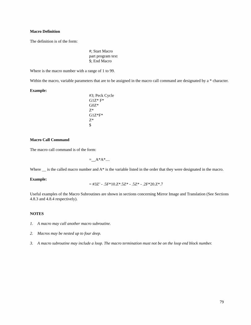
Macro Definition
The definition is of the form:
#; Start Macropart program text$; End Macro
Where is the macro number with a range of 1 to 99.
Within the macro, variable parameters that are to be assigned in the macro call command are designated by a * character.
Example:#3; Peck CycleG1Z* F*G0Z*Z*G1Z*F*Z*$
Macro Call Command
The macro call command is of the form:
=__A*A*....
Where __ is the called macro number and A* is the variable listed in the order that they were designated in the macro.
Example:= #3Z’ - .5F*10.Z*.5Z* - .5Z* - .2F*20.Z*.7
Useful examples of the Macro Subroutines are shown in sections concerning Mirror Image and Translation (See Sections4.8.3 and 4.8.4 respectively).
NOTES
1. A macro may call another macro subroutine.
2. Macros may be nested up to four deep.
3. A macro subroutine may include a loop. The macro termination must not be on the loop end block number.
79

4. A macro call may be included in a loop.
5. Macros with a specified name may be defined and redefined many times within a part program. If two macros withthe same numbers are specified within a program, the last macro defined is the one called.
6. A macro CANNOT be defined within another macro.
7. The number of unspecified variables within the macro and the number of assignments in the call command MUSTbe the same.
8. The macro call statement can contain up to 132 characters. The total number of active macro variables (includingnested macro variables) is 12.
9. The maximum input value for a macro variable is determined by the word addressed, refer to MaximumProgrammable Dimensions in Table 2-2.
The following parameters may not be used as macro variables:
Macro definition, macro callLoop callCutter compensation valuesTool offset values
Arithmetic expressions and variable substitutions may be used within a macro.
PARAMETRIC PART PROGRAMMING LANGUAGE— 3 PL
Labels
Labels are used to identify part program blocks such that they may be recalled later in the program. The label number isa single digit number, 1-9. If used, the label must be the first word used in the block. The label call causes part programexecution to jump back to the block prefixed by the designated label.
Example:L1GOG90X5.; Label DefinitionX0.=L1; Label Call (End loop)
Labels may be reused as required in the program. The milling and drilling canned cycles are defined as system routinesand have labels L8 and L9 inserted in them. Do not use these labels when looping back over blocks containing millingand drilling canned cycles. See Table 10-1.
Arithmetic Expressions
An expression evaluator assigns values for variables that can be used within a part program block instead of aspecifically defined value. The format for a variable assignment is:
A = expression
Where A is the alphabetic character defining one of the allowable variables used in the system and is any number from1-9.
The allowable variables are any alphabetic character A through Z.
80
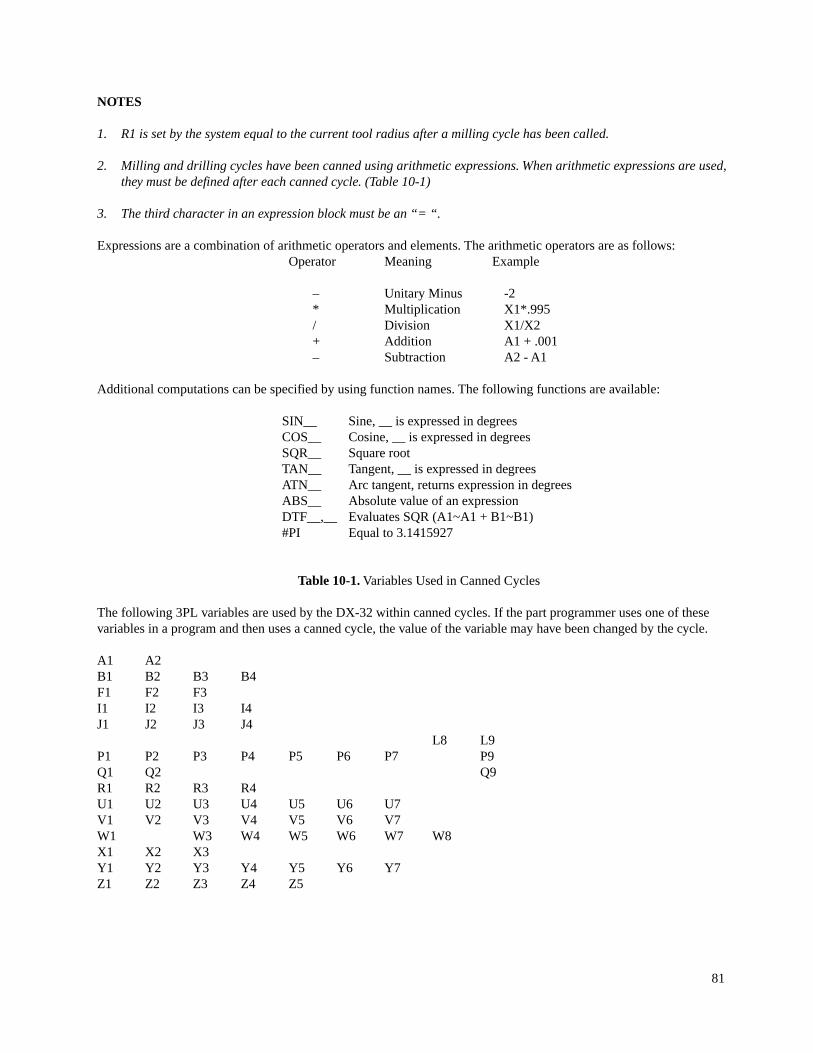
NOTES
1. R1 is set by the system equal to the current tool radius after a milling cycle has been called.
2. Milling and drilling cycles have been canned using arithmetic expressions. When arithmetic expressions are used,they must be defined after each canned cycle. (Table 10-1)
3. The third character in an expression block must be an “= “.
Expressions are a combination of arithmetic operators and elements. The arithmetic operators are as follows:Operator Meaning Example
– Unitary Minus -2* Multiplication X1*.995/ Division X1/X2+ Addition A1 + .001– Subtraction A2 - A1
Additional computations can be specified by using function names. The following functions are available:
SIN__ Sine, __ is expressed in degreesCOS__ Cosine, __ is expressed in degreesSQR__ Square rootTAN__ Tangent, __ is expressed in degreesATN__ Arc tangent, returns expression in degreesABS__ Absolute value of an expressionDTF__,__ Evaluates SQR (A1~A1 + B1~B1)#PI Equal to 3.1415927
Table 10-1.Variables Used in Canned Cycles
The following 3PL variables are used by the DX-32 within canned cycles. If the part programmer uses one of thesevariables in a program and then uses a canned cycle, the value of the variable may have been changed by the cycle.
A1 A2B1 B2 B3 B4F1 F2 F3I1 I2 I3 I4J1 J2 J3 J4
L8 L9P1 P2 P3 P4 P5 P6 P7 P9Q1 Q2 Q9R1 R2 R3 R4U1 U2 U3 U4 U5 U6 U7V1 V2 V3 V4 V5 V6 V7W1 W3 W4 W5 W6 W7 W8X1 X2 X3Y1 Y2 Y3 Y4 Y5 Y6 Y7Z1 Z2 Z3 Z4 Z5
81

NOTES
1. The result of ATN is a value between - 90 and + 90 degrees.
2. An arithmetic expression may consist of a single element.
Example:- X422.75
Or a combination of arithmetic operators, functions and/or values.
Example:1 + R1 *COS(A1/2.)
Arithmetic expressions should be enclosed in parenthesis and considered a basic element to be evaluated before use inthe remainder of an expression. This is recommended practice. Within a basic element, the order of operator evaluationis unitary minus, multiplication, division, addition and subtraction.
Example:- P1 ~SQR2 + R1 ~COS(A1/2.)P4 - P1/P2 + P3((P4 - P1)/P2) + P3(P4 - P1)/(P2 + P3)P4 - (P1/P2) + P3P4 - (p1/(P2 + P3))
Variable Substitution
Variables can be substituted for words within a data block. The character defining the variable is used for the wordaddress in the block.
Example:X1 = 1 .N1X1Y1 .0
The value equated to X1 is used as the value for the X word.
NOTES
1. A, B, C, D, E, F, I, J, K, P, Q, R, U, V, W, X, Y, Z words without a decimal point are assumed to be variables. Thus,part programs input for previous versions of BOSS that do not contain decimal points for these data fields must berun under BOSS 4-7 compatibility mode or edited.
2. The range of variable subscripts is 1 to 9. If the range of the variable is greater than 9 (for example, X10), an errorcondition is reported.
3. The following letters should not be used as variables in 3PL programs:
G, H, L, M, N, S, T (The letter O may be used; however, to avoid confusion with the number zero its use as avariable should be avoided.)
82

Conditional Part Program Execution
An IF type statement provides the ability to conditionally execute part program blocks depending on the truth of aconditional expression.
Relational operators are used to compare the value of a variable with another variable or value. The relational operatorsused are:
Relational Operator Conditional Test
<GE> Greater than or equal to<GT> Greater than<LE> Less than or equal to<LT> Less than<EQ> Equal to<NE> Not equal to
The format of the conditional test data block is:
? A__<relational operator> B__
Where A__ is the variable to be tested against B__ and B__ is either the second variable or a value. If the condition isnot true, then execution of the following part program blocks up to a block terminated by a ! character does not occur.
Conditionals may be nested as many times as required.
Example:X1=.1; Set X1 equal to .1L1G0X1; Move rapid to the value of the variable X1X1 =X1+.01; Increment X1 by .01?X1<LE>1.; If X1 less or equal to 1=L1!; Then go to the block labeled L1 else do next block
NOTE
The expression evaluator handles data in floating point format. The floating point format is precise to 7 decimal digits.For example, multiplying 1000. by .0001 is not precisely equal to . 1. Care should be taken when testing for the < EQ>condition.
83
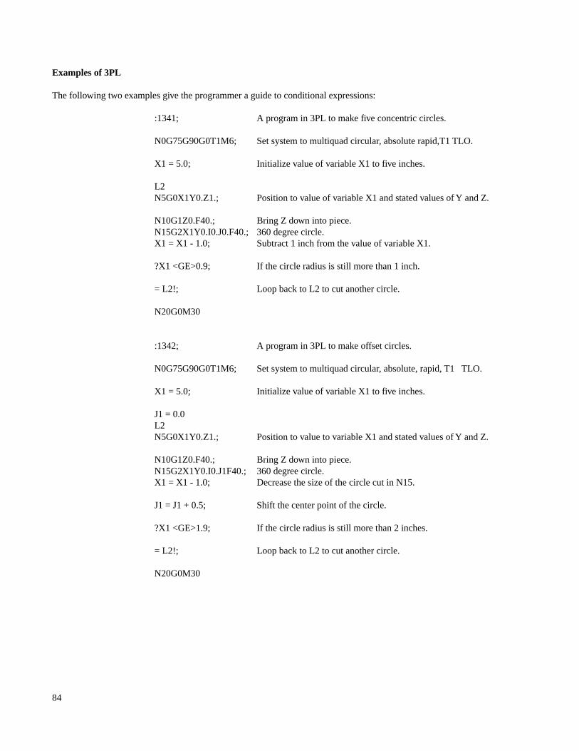
Examples of 3PL
The following two examples give the programmer a guide to conditional expressions:
:1341; A program in 3PL to make five concentric circles.
N0G75G90G0T1M6; Set system to multiquad circular, absolute rapid,T1 TLO.
X1 = 5.0; Initialize value of variable X1 to five inches.
L2N5G0X1Y0.Z1.; Position to value of variable X1 and stated values of Y and Z.
N10G1Z0.F40.; Bring Z down into piece.N15G2X1Y0.I0.J0.F40.; 360 degree circle.X1 = X1 - 1.0; Subtract 1 inch from the value of variable X1.
?X1 <GE>0.9; If the circle radius is still more than 1 inch.
= L2!; Loop back to L2 to cut another circle.
N20G0M30
:1342; A program in 3PL to make offset circles.
N0G75G90G0T1M6; Set system to multiquad circular, absolute, rapid, T1 TLO.
X1 = 5.0; Initialize value of variable X1 to five inches.
J1 = 0.0L2N5G0X1Y0.Z1.; Position to value to variable X1 and stated values of Y and Z.
N10G1Z0.F40.; Bring Z down into piece.N15G2X1Y0.I0.J1F40.; 360 degree circle.X1 = X1 - 1.0; Decrease the size of the circle cut in N15.
J1 = J1 + 0.5; Shift the center point of the circle.
?X1 <GE>1.9; If the circle radius is still more than 2 inches.
= L2!; Loop back to L2 to cut another circle.
N20G0M30
84