bridge vehicle loading - atirsoft.com
TRANSCRIPT

Atir Software Development LTD
STRAP Bridge Vehicle Loading
Bridge Module
Prepared by Elisha. P. Tungamirai BEng Hons Civil (NUST)
All rights, including those of translation, are reserved.
No portion of this document may be reproduced, including photocopying without a written permission
from Atir Engineering software LTD.
© Atir Engineering software LTD
13 Khilat Saloniki, Tel Aviv, Israel
Tel: +972-3-6480129
Website: https://atirsoft.com
Email: [email protected]
Bridge Vehicle Loading 2
Table of contents
1. ABSTRACT .................................................................................................................................................. 3
2. DESCRIPTION OF BRIDGE .................................................................................................................... 3
3. STRAP Bridge Module ........................................................................................................................... 5
3.1 NA LOADING (Normal Loading) .................................................................................................. 5
3.1.1 Lane Definition .......................................................................................................................... 6
3.1.2 Step 1: NA Notional Lanes .................................................................................................... 6
3.1.3 Step 2: Displaying Influence Lines ..................................................................................... 7
3.1.4 Step 3: Application of NA Loading .................................................................................... 8
3.1.5 Step 4: Display Output Results .......................................................................................... 10
3.1.6 Step 5: Transferring Output to Results ........................................................................... 11
3.2 NB LOADING (Abnormal Loading) .......................................................................................... 12
3.2.1 Lane Definition ........................................................................................................................ 13
3.2.2 Step 1: NB Vehicle Lane ....................................................................................................... 13
3.2.3 Step 2: Displaying Influence Lines ................................................................................... 14
3.2.4 Step 3: Application of NB Loading .................................................................................. 14
3.2.5 Step 4: Display Output result ............................................................................................. 14
3.2.6 Step 5: Transferring Output to Results ........................................................................... 15
3.3 NC LOADING (Super Loading) ................................................................................................... 15
3.3.1 Lane Definition ........................................................................................................................ 16
3.3.2 Step 1: NC Vehicle Lane ....................................................................................................... 16
3.3.3 Step 2: Displaying Influence Lines ................................................................................... 16
3.3.4 Step 3: Application of NC Loading .................................................................................. 16
3.3.5 Step 4: Display Output result ............................................................................................. 17
3.3.6 Step 5: Transferring Output to Results ........................................................................... 17
4. REFERENCES ............................................................................................................................................ 18

Bridge Vehicle Loading 3
1. ABSTRACT
The purpose of this document is to guide STRAP users on how to use the Bridge module to
analyse and design a Vehicle Overpass Bridge. Note that the loading magnitudes and results
output might not be close to the expected output.
The document will equip the user to understand the following concepts in STRAP:
• Lane Definition
• Generating Influence Lines
• Application of Traffic Loading
• Displaying Output Results
• Transferring Output to Results module and Design combinations
2. DESCRIPTION OF BRIDGE
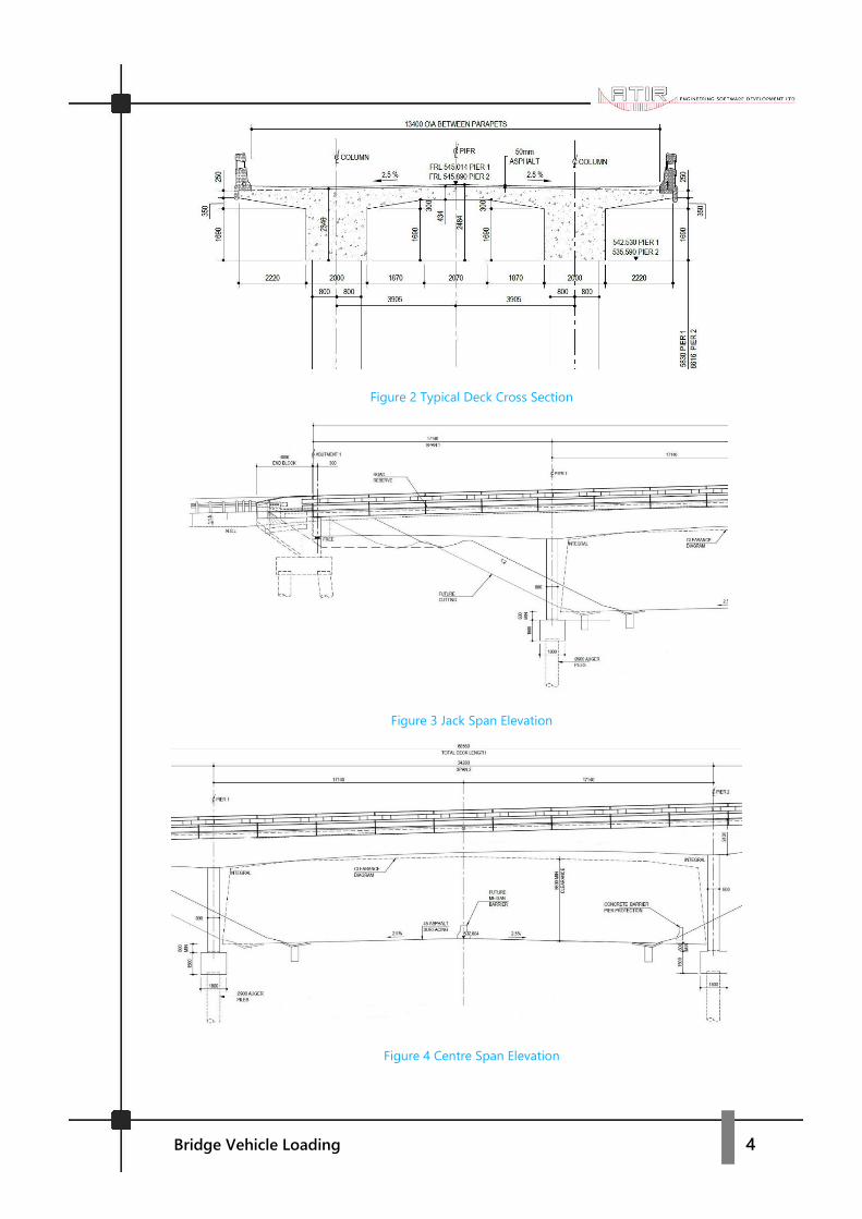
The semi-integral bridge consists of an overall length of 68.58m, with a 3-span configuration.
The twin spine post tensioned reinforced concrete deck has 17.14m jack spans and a 34.28m
centre span supported on reinforced concrete piers and closed cantilever type abutments with
return walls. The deck consists of solid deck sections over the piers and abutments mainly due
to excessive shear stresses over the supports. The twin split oblong shaped piers are cast
integrally with the deck and supported on pot bearings over the abutments. Both the abutments
and piers are founded on Augur piles and skew of bridge is 7°.
Figure 1 Full Bridge Render (Beam Model)
Bridge Vehicle Loading 4
Figure 2 Typical Deck Cross Section
Figure 3 Jack Span Elevation
Figure 4 Centre Span Elevation
Bridge Vehicle Loading 5
3. STRAP Bridge Module
Bridge design codes used by engineers around the globe require designing every point on the
bridge (both longitudinal and transverse direction) for the load combination and arrangement
that produce the most severe load effects on the bridge. The designer calculates influence lines
at every point on the bridge for each result type. The influence lines guide the designer on
where to apply the loading to achieve the most adverse moments, shear, deflections, etc. The
process become complicated as the bridge size and geometry changes. STRAP Bridge reduces
the amount of work significantly by computing various result types for every point on the
bridge. All the calculations are computed according to the designer’s input that includes
number of lanes, width of lanes, length of segments, load intensities, etc. The program
produces accurate graphical and tabulated results for any point on the bridge saving a great
deal of time compared to the strenuous manual methods.
3.1 NA LOADING (Normal Loading)
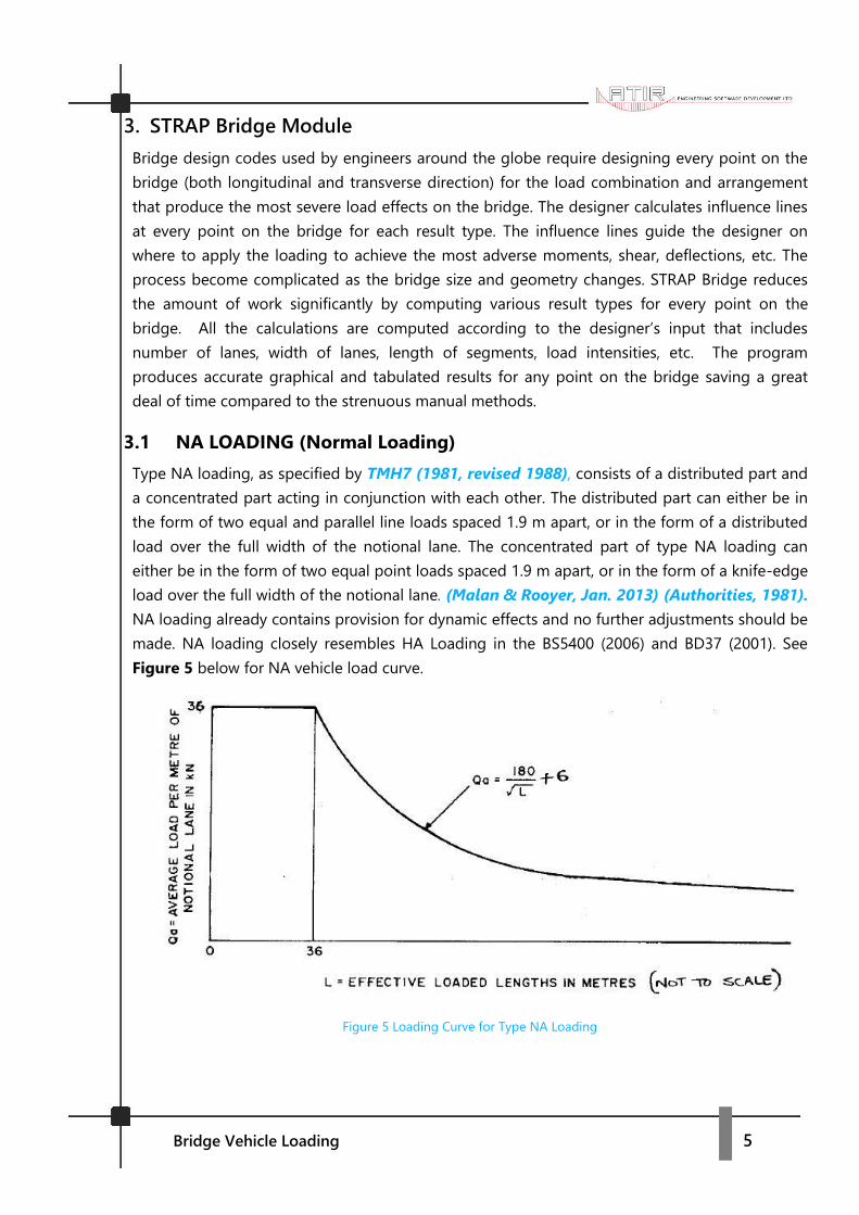
Type NA loading, as specified by TMH7 (1981, revised 1988), consists of a distributed part and
a concentrated part acting in conjunction with each other. The distributed part can either be in
the form of two equal and parallel line loads spaced 1.9 m apart, or in the form of a distributed
load over the full width of the notional lane. The concentrated part of type NA loading can
either be in the form of two equal point loads spaced 1.9 m apart, or in the form of a knife-edge
load over the full width of the notional lane. (Malan & Rooyer, Jan. 2013) (Authorities, 1981).
NA loading already contains provision for dynamic effects and no further adjustments should be
made. NA loading closely resembles HA Loading in the BS5400 (2006) and BD37 (2001). See
Figure 5 below for NA vehicle load curve.
Figure 5 Loading Curve for Type NA Loading
Bridge Vehicle Loading 6
The bridge deck overall width is 14.45m and 13.4m between the F-type parapets on both sides.
The carriageway width is 8.7m and sidewalks of 2.35m on either side. This example will
concentrate only on the STRAP Bridge module with the assumption that the user has already
completed the bridge geometry modelling. Below is a list of other parameters
associated with the analysis of the bridge:
a. Bridge spans (m) = 17.14m, 34.28m, 17.14m
b. Deck overall width (m) = 14.45m
c. Deck width between parapets (m) = 13.40m
d. Sidewalk width (m) = 2.35m
e. Carriageway width (m) = 8.70m
f. Number of notional lanes = 3
g. Width of notional lanes (m) = 2.90m
3.1.1 Lane Definition
To apply traffic loading on the bridge in STRAP, first complete geometry definition in the
Geometry module then navigate to the Bridge module to commence lane definition.
3.1.2 Step 1: NA Notional Lanes
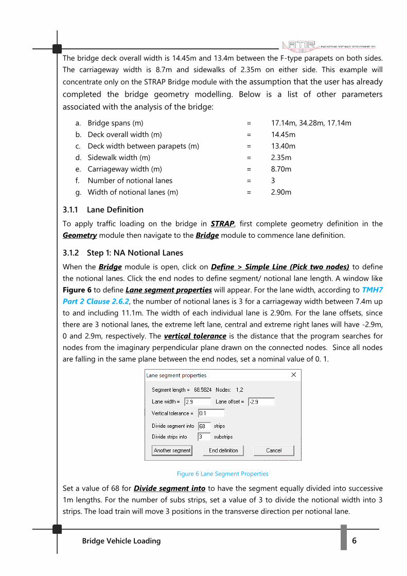
When the Bridge module is open, click on Define > Simple Line (Pick two nodes) to define
the notional lanes. Click the end nodes to define segment/ notional lane length. A window like
Figure 6 to define Lane segment properties will appear. For the lane width, according to TMH7
Part 2 Clause 2.6.2, the number of notional lanes is 3 for a carriageway width between 7.4m up
to and including 11.1m. The width of each individual lane is 2.90m. For the lane offsets, since
there are 3 notional lanes, the extreme left lane, central and extreme right lanes will have -2.9m,
0 and 2.9m, respectively. The vertical tolerance is the distance that the program searches for
nodes from the imaginary perpendicular plane drawn on the connected nodes. Since all nodes
are falling in the same plane between the end nodes, set a nominal value of 0. 1.
Figure 6 Lane Segment Properties
Set a value of 68 for Divide segment into to have the segment equally divided into successive
1m lengths. For the number of subs strips, set a value of 3 to divide the notional width into 3
strips. The load train will move 3 positions in the transverse direction per notional lane.
Bridge Vehicle Loading 7
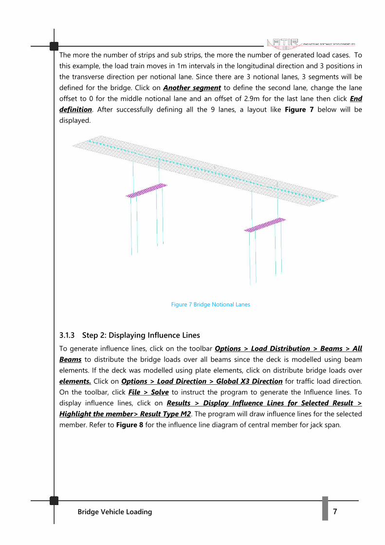
The more the number of strips and sub strips, the more the number of generated load cases. To
this example, the load train moves in 1m intervals in the longitudinal direction and 3 positions in
the transverse direction per notional lane. Since there are 3 notional lanes, 3 segments will be
defined for the bridge. Click on Another segment to define the second lane, change the lane
offset to 0 for the middle notional lane and an offset of 2.9m for the last lane then click End
definition. After successfully defining all the 9 lanes, a layout like Figure 7 below will be
displayed.
Figure 7 Bridge Notional Lanes
3.1.3 Step 2: Displaying Influence Lines
To generate influence lines, click on the toolbar Options > Load Distribution > Beams > All
Beams to distribute the bridge loads over all beams since the deck is modelled using beam
elements. If the deck was modelled using plate elements, click on distribute bridge loads over
elements. Click on Options > Load Direction > Global X3 Direction for traffic load direction.
On the toolbar, click File > Solve to instruct the program to generate the Influence lines. To
display influence lines, click on Results > Display Influence Lines for Selected Result >
Highlight the member> Result Type M2. The program will draw influence lines for the selected
member. Refer to Figure 8 for the influence line diagram of central member for jack span.

Bridge Vehicle Loading 8
Figure 8 Jack Span Centre Influence Line
From the influence line shown in Figure 8 above, a conclusion can be drawn that for maximum
longitudinal moment on the jack span, fully load the first span, skip the adjacent span, and load
the jack span on the other side. The same goes for the influence line for the central span. The
central span must be fully loaded with no traffic loading on the adjacent spans. The program will
automatically apply the loading according to the generated influence lines for any point on the
bridge to obtain the most severe result intensity and arrangement.
3.1.4 Step 3: Application of NA Loading
NA Loading is not included in STRAP’s load train library by default. Only NB24, NB36 and NC
load trains are included. To apply NA loading, click on Lane Load located on the side bar to the
far right of the main window. Proceed to click on Define > Lane Load. A window like the one in
Figure 9 will be displayed. For notional lane 1 and the other remaining 2 lanes, input a uniform
load of 36KN/m per notional lane under uniform load as stated in the TMH7 Part 2 Clause
2.6.3.1. The code states that for loaded lengths in excess of 36m, the load is derived from the
formula Qa=(180/√L)+6 and 36KN/m per notional lane for loaded lengths up to 36m. However,
STRAP calculates the load reduction automatically from the maximum loaded length even when
the load length exceeds 36m.
For notional lane 1, max length is 68.58m, Factor table select South African and input 144KN
for Knife edge load for both shear and moment envelope. The Knife edge load is derived from
Clause 2.6.3.2.2 of TMH7 Part 2 from the equation 144/√n where n is the number of the
notional lane. As the number of lanes increases, change the max length and Knife edge load.
The uniform load should not be changed because STRAP automatically calculates the load
reduction factors with increase in max length on different notional lanes. It should be
maintained at 36KN/m per notional lane. See Figure 9 for the Lane Load Input.

Bridge Vehicle Loading 9
Figure 9 NA Loading Input
Below is Table 1 for NA Load input. The 3 lane loads are defined as follows:
Lane Loaded
Lane Load Name
Uniform Load
Max Length
Factor Table Knife Edge Load
1 NA Load Lane 1 36 68.58 South African 144
2 NA Load Lane 2 36 137.16 South African 102
3 NA Load Lane 3 36 205.74 South African 83
Table 1 NA Loading Input Table
To display the uniform load factors according to TMH7 Part 2, click on Output > Display Load
Factor Tables. To create the Load cases, click on Load Case on the side bar below Lane Load.
Click on Define > Load Case Definition and assign the load to the lanes as shown in Figure 10.
After assigning the loads to lanes, click on Create load cases by permutation > From lane > 1
to 3.
Figure 10 NA Load Case Input

Bridge Vehicle Loading 10
By clicking Create load cases by permutations, an instruction is passed to the program to
create load cases by interchanging the lane loads. The program will interchange the loading
amongst the 3 lanes as mentioned above. The most adverse effects are not necessarily obtained
when the bridge deck is fully loaded. To achieve all the various load case scenarios, the designer
can opt to load the first two notional lanes and skip the third. To do this, select the option
Create load cases by permutation > By lane groups. Put lane 1 and 2 in the same group and
lane 3 in a different group. Please refer to Figure 24 Straddling of Lanes in TMH7 Part 2 for
guidelines on Bridge deck transverse loading. Several load cases can be defined depending on
the number of load arrangements the designer desires. See Figure 11 below for definition of
permutation groups.
Figure 11 Definition of permutations groups
3.1.5 Step 4: Display Output Results
To display the results within the STRAP module, click on Results > Draw Applied Loads for
Selected Result > Click on any beam > Absolute Value Maximum > Beam Results > M2 > At
5/10 of Length. An output like Figure 12 will appear. The program will indicate the load train
position and in the case of NA loading, the position of the knife edge load and the Maximum
M2 moment value will be shown. The maximum moment for the mid span sag moment is
8164.969KNm. The result type ranges from Axial, V2, V3, Torsion, M2, M3 and deflections. The
next step is to transfer the output to the Results module. The output can also be displayed in a
table for a detailed output of every member and nodes. The same applies for influence lines
output.
Figure 12 Max M2 Moment Output

Bridge Vehicle Loading 11
3.1.6 Step 5: Transferring Output to Results
To transfer output to Results module, click on the toolbar Results > Update STRAP Results
File. See Figure 13 for the Update STRAP results file table. Give the Load a name NA Max abs
envelope and click ok to transfer the output.
Figure 13 Update STRAP results file
Click on the Results module > Draw result > Beam Result Diagram > M2. See Figure 14 below,
Figure 14 NA M2 Bending Moment Envelope
Once the results are exported to STRAP Results module, they can be included in design
combinations together with other load cases that include self-weight and other defined load
cases on the bridge. Under the Loads module, navigate to existing loads. The output from the
Bridge module will form part of the loads as an existing solution. Bending moments, shear
forces, immediate deflections, etc for the individual load case can be displayed similar to that of
other loads like dead loads, super-imposed dead loads, etc. See Figure 15 below,

Bridge Vehicle Loading 12
Figure 15 List Of Load Cases
The NA – Bridge: Max abs envelope load case is combined with other relevant load cases to
generate several load combinations as shown in Figure 16 below The NA load case is combined
with several load cases as defined in the design code the designer is using.
Figure 16 Definition of Load Combinations
N.B The advantage of using the STRAP Bridge Module for traffic loading is that the program
automatically calculates the torsion introduced in the deck due to eccentric applied loads
because of the load train moving from left to right in the transverse direction. The bridge
module incorporates guidelines stated in Appendix 2.A Clause 2.A.2.4 Figure 24 (a and b) for
Extreme transverse positions for NA Loading on 2, 3 Lanes in TMH7 Part 2.
3.2 NB LOADING (Abnormal Loading)
TMH7 Part 2 Clause 2.6.4.2 states that the NB vehicle shall be taken to occupy any transverse
position within the length of the carriageway it is in and to be within 0.6m from the face of a
kerb, except that when the distance between the kerb and the balustrade exceeds 0.6m it shall
be placed up to within 0.15m from the face of the kerb. For this example, the NB vehicle will be
placed 0.15m from the edge of kerb on sidewalk because the distance between the yellow line
and kerb exceeds 0.6m. NB loading is a unit loading representing a single abnormally heavy

Bridge Vehicle Loading 13
vehicle. NB loading closely resembles HB Loading in the BS5400 (2006) and BD37 (2001). Only
one NB vehicle is permitted on a bridge at any given time and does not coexist with any other
vehicle load. NB loading is typically applied in two magnitudes namely NB24 and NB36, with the
number referring to the number of units applied. NB24 has an axle load of 240 kN and NB36 an
axle load of 360 KN. The magnitude of NB loading is determined by the class of road and the
relevant authority. There is no allowance for dynamic effects on the NB vehicle load train. See
NB load train in Figure 17 below,
Figure 17 NB Load Train from TMH7 Part 2
3.2.1 Lane Definition
There are no notional lanes in NB Loading unlike in the case of NA. Define a lane from start of
bridge to the end. The code states that a NB vehicle can occupy any position along the length of
the bridge and 0.15m from the kerb on either side.
3.2.2 Step 1: NB Vehicle Lane
Below are the parameters for lane definition:
• The lane width is 8.70m-(2*0.15)m = 8.40m
• Lane offset = 0m
• Vertical tolerance = 0.1
• Divide segment into = 68
• Divide strips into sub strips = 8
Bridge Vehicle Loading 14
3.2.3 Step 2: Displaying Influence Lines
The same procedure followed on NA loading for display of Influence lines is applied for NB
loading. The influence lines will give an indication of the position of the NB load train to get the
maximum moment on any longitudinal position of the bridge. STRAP will move the load train 68
times in the longitudinal direction in both directions and 8 times in the transverse direction per
every 1m movement in the longitudinal direction.
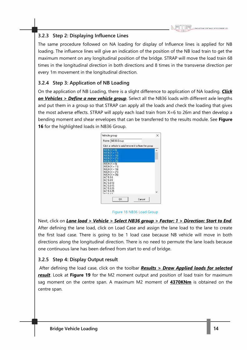
3.2.4 Step 3: Application of NB Loading
On the application of NB Loading, there is a slight difference to application of NA loading. Click
on Vehicles > Define a new vehicle group. Select all the NB36 loads with different axle lengths
and put them in a group so that STRAP can apply all the loads and check the loading that gives
the most adverse effects. STRAP will apply each load train from X=6 to 26m and then develop a
bending moment and shear envelopes that can be transferred to the results module. See Figure
16 for the highlighted loads in NB36 Group.
Figure 18 NB36 Load Group
Next, click on Lane load > Vehicle > Select NB36 group > Factor: 1 > Direction: Start to End.
After defining the lane load, click on Load Case and assign the lane load to the lane to create
the first load case. There is going to be 1 load case because NB vehicle will move in both
directions along the longitudinal direction. There is no need to permute the lane loads because
one continuous lane has been defined from start to end of bridge.
3.2.5 Step 4: Display Output result
After defining the load case, click on the toolbar Results > Draw Applied loads for selected
result. Look at Figure 19 for the M2 moment output and position of load train for maximum
sag moment on the centre span. A maximum M2 moment of 4370KNm is obtained on the
centre span.

Bridge Vehicle Loading 15
Figure 19 NB Load train position for max sag moment span 2
3.2.6 Step 5: Transferring Output to Results
The results are transferred the same way as described on NA Loading. Follow the same steps
described on NA loading to transfer the NB loading to the Results module. See Figure 20
below for output of maximum sag moment on span 2 from the Results module.
Figure 20 NB36 M2 Bending Moment Envelope
After exporting the NB – Bridge: Max abs envelope to the Result module, follow the same steps
described under NA loading for incorporating the NB36 load case into the load combinations
for analysis and design to obtain the maximum bending moments, shear forces, deflections, etc
at any point in the longitudinal and transverse directions on the bridge.
3.3 NC LOADING (Super Loading)
TMH7 Part 2 Clause 2.6.5.2 states that the NC loading shall be directed along the centre line
of any carriageway unless otherwise dictated by road geometrics, with an allowance for moving
off-line by 1m in either direction or in such a position as to cause the most severe effect on the
member being analysed. For this example, NC loading with a width (b) = 5m will be used to get
the maximum bending moments, shear etc… for the bridge deck. NC load train represents
multi-wheeled trailer combinations with controlled hydraulic suspension and steering intended
to transport very heavy indivisible payloads. The loading is uniformly distributed over the area
shown with an intensity of 30 KN/m2. Dynamic effects are already incorporated in the NC
loading and two thirds of NA loading can coexist with NC loading. See Figure 21 below from
TMH7 Part 2 for the NC Load Train.
Bridge Vehicle Loading 16
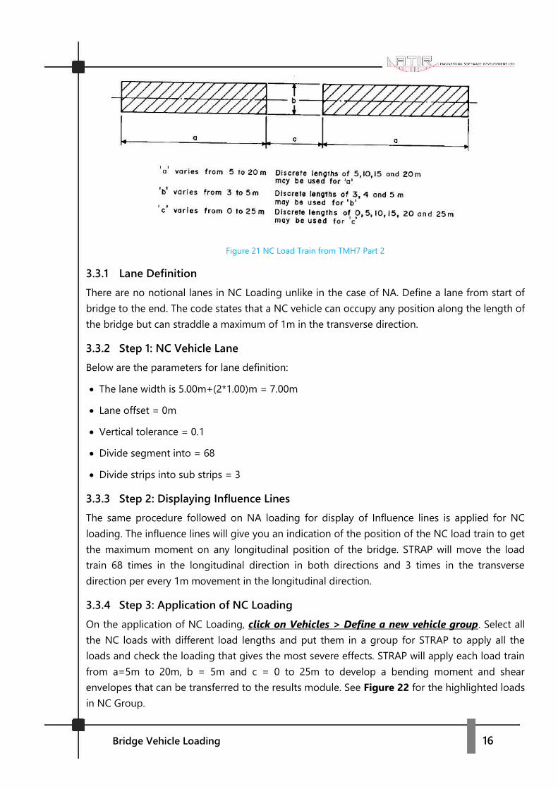
Figure 21 NC Load Train from TMH7 Part 2
3.3.1 Lane Definition
There are no notional lanes in NC Loading unlike in the case of NA. Define a lane from start of
bridge to the end. The code states that a NC vehicle can occupy any position along the length of
the bridge but can straddle a maximum of 1m in the transverse direction.
3.3.2 Step 1: NC Vehicle Lane
Below are the parameters for lane definition:
• The lane width is 5.00m+(2*1.00)m = 7.00m
• Lane offset = 0m
• Vertical tolerance = 0.1
• Divide segment into = 68
• Divide strips into sub strips = 3
3.3.3 Step 2: Displaying Influence Lines
The same procedure followed on NA loading for display of Influence lines is applied for NC
loading. The influence lines will give you an indication of the position of the NC load train to get
the maximum moment on any longitudinal position of the bridge. STRAP will move the load
train 68 times in the longitudinal direction in both directions and 3 times in the transverse
direction per every 1m movement in the longitudinal direction.
3.3.4 Step 3: Application of NC Loading
On the application of NC Loading, click on Vehicles > Define a new vehicle group. Select all
the NC loads with different load lengths and put them in a group for STRAP to apply all the
loads and check the loading that gives the most severe effects. STRAP will apply each load train
from a=5m to 20m, b = 5m and c = 0 to 25m to develop a bending moment and shear
envelopes that can be transferred to the results module. See Figure 22 for the highlighted loads
in NC Group.
Bridge Vehicle Loading 17
Figure 22 NC Group Definition
Next, click on Lane load > Vehicle > Select NC group > Factor: 1 > Direction: Start to End.
After defining the lane load, click on Load Case and assign the lane load to the lane to create
the first load case. There is going to be 1 load case because NC vehicle will move in both
directions along the longitudinal direction. There is no need to permute the lane loads because
there is one continuous lane from the start to the end of bridge.
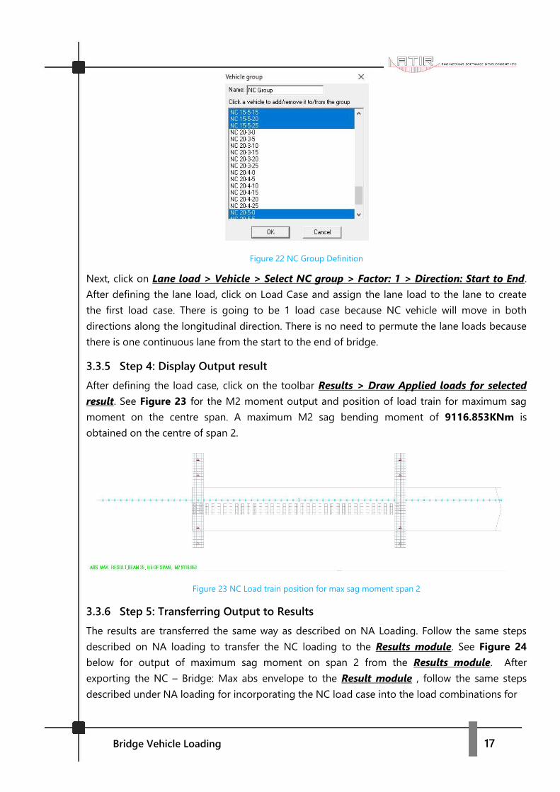
3.3.5 Step 4: Display Output result
After defining the load case, click on the toolbar Results > Draw Applied loads for selected
result. See Figure 23 for the M2 moment output and position of load train for maximum sag
moment on the centre span. A maximum M2 sag bending moment of 9116.853KNm is
obtained on the centre of span 2.
Figure 23 NC Load train position for max sag moment span 2
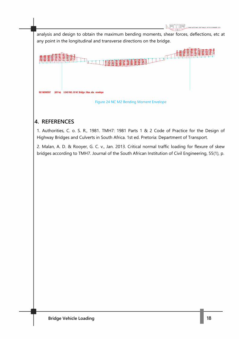
3.3.6 Step 5: Transferring Output to Results
The results are transferred the same way as described on NA Loading. Follow the same steps
described on NA loading to transfer the NC loading to the Results module. See Figure 24
below for output of maximum sag moment on span 2 from the Results module. After
exporting the NC – Bridge: Max abs envelope to the Result module , follow the same steps
described under NA loading for incorporating the NC load case into the load combinations for
Bridge Vehicle Loading 18
analysis and design to obtain the maximum bending moments, shear forces, deflections, etc at
any point in the longitudinal and transverse directions on the bridge.
Figure 24 NC M2 Bending Moment Envelope
4. REFERENCES
1. Authorities, C. o. S. R., 1981. TMH7: 1981 Parts 1 & 2 Code of Practice for the Design of
Highway Bridges and Culverts in South Africa. 1st ed. Pretoria: Department of Transport.
2. Malan, A. D. & Rooyer, G. C. v., Jan. 2013. Critical normal traffic loading for flexure of skew
bridges according to TMH7. Journal of the South African Institution of Civil Engineering, 55(1), p.