bridge strengthening by conversion to network arch. design
TRANSCRIPT

Bridge strengthening by conversion to network arch. Design criteria and
economic validation
Matías A. Valenzuela* and Joan R. Casas
Public Works Department, Santiago, Chile – UniversitatPolitecnica de
CatalunyaBarcelonaTech, Barcelona, Catalunya-Spain
Morandé 71, [email protected], phone: +56956374031
Bridge strengthening by conversion to network arch. Design criteria and
economic validation
The paper presents a new strengthening methodology in bridges over river beds affected by
scour and erosion at piers. The proposal is part of an innovative concept, implementing a
structural change of the original bridge, without the need to strengthen the substructure,
thanks to the construction of an upper arch with network and vertical hanger's. The vertical
hangers are responsible to lift the deck from the piers, generating a single span (simply-
supported tied arch). The paper describes the construction phases, considering the
conditions and difficulties in their implementation due to multi-objective targets and
additional boundary conditions and requirements. Additionally, it gives a description of the
structural behavior and a layout of each element, to use as criteria or guideline for future
applications of the method. Finally, a validation is made through a comparative analysis in
a Chilean bridge, between a traditional method of strengthening by additional piling in the
foundations and the proposal here presented. Additionally to the feasibility of application,
the example shows that the new solution is cheaper.
Keywords: network arch; strengthening; scour;hanger; lifting
1.Introduction
One of the major problems in bridges over riverbeds is the scour in the foundations. The
consequences are of varying severity, but certainly the most important is the total collapse of the
structure, generating high human and economic costs. As a result, they have been implemented
several measures of inspection, monitoring and maintenance, not properly applied at underwater
infrastructure conditions. In addition, the action of accidentals loads (earthquake) and the poor
support conditions produce a highly vulnerable and risky scenario for these bridges.
In Andean countriessuch as Chile, one of the most common problems is the undermining
of the piers (Muñoz, 2006; Seaurz, 2006). The repair and strengthening are frequent and generate
high economic losses. The damage caused by the flow streamin Andean rivers is important
because they are of torrential nature, able to move large and heavy rocks. These factors induce a

high risk in the piers, which are eroded in their foundations and can be themselves fully
destroyed by the passage of the water flow.
Figure 1. Scour at bridge piers.
The condition of the foundation because of the scour, leaving the piles out of the ground
as shown in Figure 1, is extremely dangerous in countries with high seismic activity, requiring a
constant monitoring, repair and strengtheningbyadditional piles (steel or concrete) and screeds.
For this reason, the Ministry of Public Works of Chile, through the Department of Bridges has
promoted the study and development of an alternative strengtheningmethod for this type of
damage.
Mitigation mechanisms have been developed, which often extend the service life of the
structure. However, many of them present difficulties in their implementation (require qualified
personnel and are very expensive).Among the traditional repair methods are those used for the
protection of the channel and bridge elements. Frequent techniques correspond to: the armoring
protection around the piersand the river bed (Figure 2), dam construction, the increase of the
span of the bridge and constant monitoring of the scour. These techniques, in emergency cases,
improve the conditions of the bridge. However, they present the disadvantage of physical
changes to the river flow, and the requirement to work in complex access conditions, deriving on
high costs of materials and labor.

Figure 2. Protected armoring. [Courtesy of B. Moya]
Other protection techniques are the improvement of resistance of elements and structural
support. As an example, the concrete screed, mortars using mixed cement with sand, gravels and
aggregates (bagged concrete or fluid micro-concrete) improve the strength and structural support
at the base level (Figure 3). When the foundation is under water, the application is through pipe
systems or injecting a concrete grout to fill any existing hole. The main drawback is the
geometrical increase of the area exposed to the river current and the changein flow patterns,
inducing future erosion problems.
Figure 3. Concrete screeds.[Courtesy of B. Moya]
Finally, to improve the bearing capacity, the most commonly technique used is the
strengthening by additional piles (Figure 4). These enable to transfer the loads to a capable layer
of soil when it is at a considerable depth. It is a common technique which requires a detailed
study of soil stratigraphy and geology, looking for a good support layer. Despite its good

performance and wide variety of techniques (kneeling, percussion, excavated) and materials
(steel, concrete, and wood) this method presents a number of drawbacks, including:
• Difficulty of implementation (limited access of the equipment, vertical clearance,
inclined piles).
• Depth of foundations (Placing reinforcement and concrete joints, false rejections in the
driving, presence of thin hard layers).
• Incompatibility between construction method and soil type (e.g. driving in the presence
of coarse gravel, on-site method in locations not permitting shoring and movement of
material).
• Durability of the material. (Steel corrosion or wood rottenness in unsaturated zone).
Figure 4. Strengthening by piles.[Courtesy of B. Moya]
Another technique is to strengthen by micro-piles. They are used in areas where is not
possible to implement conventional piles by difficulty in the access. Among its advantages, is the
fast implementation and minimal discomfort at worksite.However, the micro-pile bearing
capacity is lower than that of the piles, requiring a large number of them, thus increasing the
cost. Also, it is not usable in very deep foundations, and does not provide a good response to
lateral actions in the presence of a seismic event. Normally, the strengthening sequence is as

follows: After the collapse of the piers and placement of provisional supports, the superstructure
is released from the piers, and it is lifted by jacks. Then, the damaged part is demolished, and the
foundations strengthened by piles or driving caissons. Finally, the pier is rebuilt and the
superstructure is placed again into place (Valenzuela, 2012). This technique improves the
bearing capacity of the piers and locates the foundation level below the general and local scour,
delivering anoptimum configuration. However, the interference of current flow is not eliminated,
requiring future inspections and monitoring of the area.
In Malerba (2014), some examples of problems in bridges due to scour and the
techniques used to strengthen the foundations are presented.
2. New strengthening methodology
A new strengthening method of short andmedium-span bridges, with several continuous spans is
proposed. The method performs the modification of the static scheme (from continuous beam to
tied-arch) by building an upper-deck arch with a network hanger arrangement, in which the
existing deck becomes the tie of the system. This allows the removalof the intermediate supports,
generating a single span, thereby eliminating anyfuture scour problems (Valenzuela, 2012;
Valenzuela & Casas, 2013). The main characteristic of network arch bridges is that the inclined
hangers cross each other at least twice. They have demonstrated an excellent performance for the
construction of new bridges (Tveit, 2007; Valenzuela, 2012; Pircher et al., 2013). In the present
case, the network arch is used in the strengthening of an existing bridge.
This new method of strengthening is sustainable due to the decrease of the repair costs,
avoiding repetitive and expensive repairs and strengthenings in the foundations and piers.
Additionally, it delivers a new significance to the repair concept, providing an enhanced
aesthetic solution. The proposal is part of a philosophy of repair and strengthening of bridges
with emphasis on the reuse of components, allowing structural and economic benefits and
providing additional aesthetic value.

Based on the analysis of the construction process, the method proposes a verification
associated to the definition of and upper and lower bound and an acceptance bandwidth based on
these bound values. The method can be applied to bridges with little initial information, i.e., lack
of detailed drawings, steel reinforcement, and types of materials, through the study of admissible
ranges of stress (MAB) (Valenzuela, 2012; Valenzuela & Casas, 2013).The range corresponds to
threshold values obtained by the analysis of theactual stressesin the bridge under analysis. To
this end, based on the actions present in the existing bridge, the actual state of stressin the deck is
obtained. These maximum and minimum limits in the service state can not be overpassed by the
existing deckduring the different phases of the strengthening application and later on in the new
service phase of the strengthened bridge.
The initial step in the strengthening methodology corresponds to the calculation of the
maximum stress state in the original deck over piers due to the actual loading conditions and
feasible load combinations. If the information gathered is insufficient, a geometric survey and
material coredrilling and testing may be required to up-date the limited available information.
The proposed newstrengthening procedure is divided into three phases, as follows:
2.1. Preparation Phase.
During this phase is evaluated the need to improve the deck geometry according to current
standards (e.g., incorporating an extension of the carriageway, enlarging the width of the existing
lanes,…) or because of the additional space required by the strengthening process itself, for
instance, the reconstruction of the carriageway with the necessary dimensions to deploy the arch
at the center of the cross-section. It should be also assessed the scour condition and resistance
capacity of the abutments to accommodate the additional vertical force transmitted in the new
static scheme. (Figure 5.a).

Figure 5.a.Modification in superstructure (a)
The changesthat will be applied to the deck require the use of temporary towers on the
original deck, located over each pier to accommodate the arch segments. The arch segments are
placed over the towers through the use of cranes. The number of arch segments will depend on
the crane capacity (Figure 5.b.).
Figure 5.b. Construction of the upper arch (b).
After the deployement of the arch segments, the longitudinal beams composing the deck
cross-section are unlinked from the piers by cutting them (e.g., through diamond wire), leaving
the superstructure simply-supported on the piers. Then, it is necessary to incorporate an element
acting as the tie of arch between the two abutments of the bridge. This is accomplished by the
use of external prestressing with straight tendons from abutment to abutment (Figure 5.c.).
Figure 5.c.Externalprestressing in the deck (c)

After post-tensioning the deck with the external tendons, the temporary towers can be
removed, avoiding excessive strain in the arch. Later on are deployed two groups of passive
hangers (network and retention), and the vertical hangers without applying any tensioning
(Figure 5.d).
Figure 5.d.Deployement of network hangers (d).
The network hangers follow a configuration such that they cross each other at least twice
(Tveit, 2007). The retention hangers correspond to the set of hangers placed near the junction
between deck and arch, to regulate the negative bending moments in the deck at this point.
After the placement of the passive hangers, the first phase of the construction is
completed. It should be noted that in these early stages, the requirement to be fullfilled is: "avoid
that the stress at any point, in any of these stages, exceeds the limits set by the MAB". Following
this recommendation, the critical point is normally located in the deck, since this is the zone
where the reference stressbandwidth (MAB) is more restrictive.
2.2. Lifting Phase.
The second phase corresponds to the tensioning of thethe vertical hangers, which are responsible
for gradually lifting the deck from the piers, as shown in (Figure 5.e).

Figure 5.e. Tensioning of vertical hangers (e)
The proposed sequence of tensioning considers the introduction of the total force in the
vertical hangers by only one jacking operation, reducing the number of tensioning operations to a
minimum to optimize the cost. As a basic arrangement, the vertical hangersare placed over each
original pier. At this point, the sequence and magnitude of the tension in each vertical hanger to
achieve adequate lift of the deck should be defined. Thestructural analysis starts from the stress-
strain state obtained at the end of the preparation phase, and follows the guidelines of the
criterion of MAB (Valenzuela, 2012; Valenzuela & Casas, 2013).
The lifting phase of the deck is the most complex and delicate operation throughout the
process of bridge strengthening. It involves a large number of parameters and variables that
affect the response of the structure and define the success of the operation, considering all the
stress changes in the deck due to the introduction of the force in the hangers. In this stage is
when, in fact, the change of the structural longitudinal configuration (from continuous beam to
arch) occurs. For this reason, this phase is considered fundamental in the strengthening process.
The major computational efforts are present in this phase, as the tension introduced in the
hangers must lift the deck and leave it in an allowable stress state during both the construction
and the in-service phases. Therefore, it is necessary to obtain safe and acceptable values of the
jacking sequence and the magnitude of the jacking force in the hangers, through an optimization
tool, solving a multi-objective optimization problem by means of genetic algorithms
(Valenzuela, 2012; Valenzuela & Casas, 2013). The algorithm is formulated through the
combination of discrete and continuous variables, without an explicit objective function. It

optimizes two variables: order of tensioning and magnitude of the force to be introduced in the
vertical hangers. The optimization seeks to reduce the differences between the original stress on
the deck and those after each tensioning phase to lift the superstructure, allowing the lifting of
the deck over each pier and maintaining a state of allowable stresses in all bridge elements (old
and new). In addition, the optimization also searchs to use the minimum amount of materials and
minimum number of jacketing operations (economical constraints) (Valenzuela & Casas, 2011;
Goldberg, 2002).
2.3. Network phase.
If necessary, in this phase the tensioning process in each hanger network is defined. Only the
network hangers that require an initial tensioning will be stressed. This is defined according to
the structural analysis of the bridge during the in-service operation. The location of hangers
corresponds to a spacing not greater than 4 meters at the arch and a symmetrically configuration.
Considering this, the tension of these hangers meets the needs of an efficient structural
performance in the service stage (Valenzuela, 2012).
Finally, when the deck is completely supported by the hangers, the piers are demolished
(Figure 5.f) and the new network arch configuration is obtained.
Figure 5.f.Removalof the piers (f).
3. Design criteria
The basic criteria to define the elements used inthe strengthening method include the arch,
hangers, and the modification of the deck. Based on a great number of calculations and

parametric studies (Valenzuela, 2012), it has been possible to deliver a summary of these design
criteria. According to the significance coefficients obtained from multivariate studies
(Valenzuela, 2012; Valenzuela & Casas, 2013), the greatest impact upon the correct performance
of the strengthening comes from the type of profile used in the arch, the external prestressing
layout and the weight of the deck. In the following, the proposeddesign criteria based on a
parametric study are presented. Further information on how they are derived can be seen in
(Valenzuela, 2012; Valenzuela & Casas, 2013).
3.1. Arch
(1) Behavior
The arch is the main design element. It is proposed the use of a single arch centered and placed
over the longitudinal beam, seeking for a reduction of material and number of operations. The
internal forces in the arch are composed of staggered axial forces and bending moments in the
plane, similar to the behavior of a continuous beam,i.e., it is composed by negative peaks at the
points of application of the vertical hangers. However, these peaks have a decrease along length
due to the secondary effects of alternation of the bending moments provoked by the network's
hangers.
The bending moments in the plane of the arch are similar or slightly greater than the out-
plane ones. Thus, it is recommended to use symmetrical profiles. The minimum square profile
recommended is higher than the profiles used on a new construction projects. From this, the
relationship between edge arch profile and total span is higher than for new construction projects
(Valenzuela, 2010; Rongish, 2011).
When the deck has a significant width, it is necessary to use a double arch. In these cases,
the inclination of the arches is a subject to study in the future due to the fact that it induces an
axial effort in the transverse elements of the deck.

The rise-to-span ratio is relatively high, with a moderate participation in the lifting
process and in the reduction of the effects of embedment between arch and edge of the deck.
(2) Design Criteria
Based on the explained behavior and the results of the parametric study, the following design
criteria were obtained:
• When using a single centeredarch centered, it is recommended a symmetrical profile
(same inertia in the two principal directions). When using a double arch solution, it is
recommended to use arch profiles with greater inertia in the plane of the arch.
• The ratio between the inertia modulus of the arch and the longitudinal beams of the deck
should not exceed 75. This improves the ability to lift the deck without inducing a failure.
75/ ≤=
Arch
Beam
ABInertia
InertiaR
(Equation 1)
• A circular arch shape is recommended.
• A rise-to-span ratio in the order of 0.14 is recommended in those cases where the wind
effects are very important. However, in the cases where the criterion has been the profile
optimization, the rise-to-span ratio should be in the range 0.16 to 0.17. It is important to
never exceed the value 0.2.
• Due to the selected profiles, the relation cross-section depth / span should not be less than
1/127.
With these design criteria, the buckling of the arch both in and out of plane is avoided, as shown
in the analysis carried out by a Finite Element Model of the bridge (Valenzuela & Casas 2013).

3.2. Deck
(1) Behavior
In the context of strengthening, the deck is not a design variable, as it corresponds to the unique
active reused element of the original bridge, considering a static system that includes
intermediate diaphragm at mid-span. The deck section studied corresponds to continuous
longitudinal beams with transverse diaphragms, thus, the strengthening should preserve the stress
states and internal forces to those of a continuous beam bridge, with negative moments in the
areas of vertical hangers and positive in bays, with slight modification provoked by the network
hangers. This induces a decrease of maximum values in the lifting phase respect to established
limits.
The deck acts as edge beam or tie element of the system, thanks to the addition of the
external prestressing. The transverse beams are actively involved in the stress distribution
between the longitudinal beams and to face the transverse moments.
The embedment effect is a consequence of implementing the network structure
conditions, where the arch and deck are linked generating negative moment at the longitudinal
edge of the deck. Since the adequate behavior is defined as similar to continuous beam bridges,
these effects are not desired. Therefore, it is recommended to modify the geometry of the arch or
the curvature at the base of the arch; to use retention hangers or consider a new hinge joint
between arch and deck, trying to reduce or eliminate these efforts.This connection is composed
by a horizontal plate under the pin conection, in order to distribute the stress, and a vertical plate
for prestress tendon joint (Figure 6).
The incidence of the embedment effect is negligible in the beams that do not support the
arch, and when the arch has small profiles. Initially, the negative moment at the edge of the deck
is not a problem for the admissibility. However, it is advisable to use mechanisms that reduce the
effects of embedment. When the requirement of maximum allowable internal force is not

complied using a hinge joint at the base of the arch, it requires a study of the ductility of the deck
and its ability to form plastic hinges.
Figure 6. Arch-deck pinned connection.
The support system in the abutment corresponds to a simple support (fixed and
unidirectional sliding), with "pot" bearing devices (neoprene confined). These are used due to the
need to replace the original bearings, because of the increase of the vertical loads (due to
removal of the piers and the additional weight of the arch). Additionally, the problem of the
dimensions of the bearings can be reduced by the placement of more than one device under the
arch support, considering as minimum one at each beam. This also improves the behavior
because it reduces the transverse moments of the arch and produces a greater stability of the
bridge against lateral loads. The analysis of the strengthened bridge, carried out by a Finite
Element Model,shows a low distribution of the vertical loads to the beams that do not support the
arch (4 - 7%). This requires to choose between the use of a stiffening system at the edge
transverse beam to homogenize load on the bearing devices; or simply, to use bearings with
different characteristics.
(2) Design Criteria
• It is recommended to check the ductility of the deck in the link with the arch to see the
feasibility of development of plastic hinges at this pointand the ability to redistributethe

stresses in the structure. If enough redistribution capacity is guaranteed then it is
recommended to place a hinge connection between the arch and the deck.
• Internal forces at the edge of the deck.
(a) It is not recommended the change in geometry of the arch based on the efforts at the
edge of the deck.
(b) However, if the stresses at the edges exceed the MAB, and the bearing capacity and
ductility of the deck is poor, it is justified the application of passive solutions (change of
the curve of the arch, retention hanger, etc.).
• For the external prestressing it is recommended to use astraight layout placed at the
center of gravity of the deck. It is allowed an eccentricity within the range -0.1 to 0
meters, looking for reactions and adequate reductions of the axial distribution of the
network and vertical hangers.
In some cases, if the transverse beams (diaphragms) are not sufficiently designed to
accommodate the internal forces in the new static system, the local strengthening of these
elements should be also carried out.
3.3. Vertical hangers.
(1) Behavior
The vertical hangers are the active elements in the process of lifting the deck and responsible to
induce a stress state similar to the original state of the deck, replacing the original piers. They are
placed over each original pier. These hangers are fundamental in the lifting stage and the in-
service state too. They never should lose tension, nor reduce it to levels that create stress states
outside the MAB. In the same manner, the maximum tension should not exceed their material
resisting capacity or induce stress states, in the deck and arch, higher than the design criteria.

From the jacking operation in the lifting stage, the normal behavior of these hangers is in
tension. The maximum tension occurs in the service condition due to traffic load. The minimum
stress occurs associated with vertical seismic loads in the cases when the top and bottom
anchorages approach themselves.
(2) Design Criteria
• The parameter "Ad" representsa limit criteria defined by the ratio between deck weight
and its flexural resistance. This parameter is defined in the following way:
MAX
EQ
M
PtAd
)(−= (Equation 2)
Where:
PtEQ: Weight per stage equivalent, defined as2
1++
=ii
EQ
PtPtPt
Pti: Weight per span (i)
M (-) MAX: Maximum negative bending moment.
• The value of this parameter is used prior to the analysis of the strengthening
process, such that if Ad > 1.2 m-1
the iteration process of tensioning must begin with a
higher number of vertical hangers or deferred lifting loads must be considered (by a
second group of tension hangers or a multi-step tension operation after verification of the
ultimate limit state).
• Tension force and order of tensioning of the vertical hangers.
• In the multi-objective optimization, the algorithm used in this study is based on
the theory of genetic algorithms (Valenzuela, 2012) being the tension force and the order
of tensioning the variables. Therefore, a set of possible solutions (value of the tension

force and order of tensioning) is obtained at the end of the optimization (Pareto front).
The following criteria for selecting the final solution should be adopted:
(a) Choose solutions with a low-tension value of the central hanger, and a homogeneous
tension at all the vertical hangers. This achieves a better performance in the arch, deck
and in the tension of the vertical hangers.
(b)For lifting of very heavy decks (Ad > 1 m-1
), it is recommended to choose a process
where all vertical hangers are acting and the lifting is produced just when the last vertical
hanger is jacked. This avoids the appearance of non admissible peak stress in the arch
and deck.
(c) Take a jacking tension of the hangers at least 20% lower than the maximum allowable
stress (fatigue criteria). Furthermore, it is recommended a jacking tension that produces a
deflection in the permanent state 25% higher than the maximum allowable deflection.
3.4. Network hangers.
(1) Behavior
The application of a set of network hangers as part of the strengthening process solves the need
to stiffen the system and get a truss-beam system, where the arch acts as top chord and the deck
as lower chord. The network hangers are responsible to distribute the efforts from a chord to the
other. In the case of the strengthening process, the behavior of these hangers varies depending on
the construction phase and the influence of the vertical hanger.
Initially, the collaboration of the network hangers is passive, collaborating in the lifting
process, i.e. they act when the process requires it. The forces in network hangers show a
reduction of tension with the increase of the participation of the vertical hanger, due to the
deformation in the arch. This provokes a compression in some of the network hangers. Normally,
there are a reduced number of active network hangers after the end of the lifting stage. The
maximum tension (which is always checked to be less than the maximum tensile force in the
material under permanent load to avoid fatigue and also less than the material strength) is
obtained in this stage, corresponding to the hangers placed at the ends of the bridge.
Although their passive participation in the lifting process, their performance is essential
to preserve admissible stress in the deck. After the lifting phase,a tensioning process of the
network hangers is performed with the goal that all of them participate actively in the service
state, i.e. to face vertical seismic loads (without loss of tension) and traffic loads (below of
failure load). In this way, the structureperforms avoiding structural changes and assists in the
dynamic response of the bridge. Additionally, the involvement of these hangers reduces stress on
the arch and the deck against the effects of service loads.
On the other hand, there is a number of network hangers, beyond whichan increase does
not generate an improved static behavior, showing an asymptotic decrease of the benefits. When
the tension of the vertical hanger is low, it is recommended to increase the distance of the
network hangers.
The radial arrangement is the best fit of hangers. It is favorable to the process of lifting
and service, respect to rhomboid-type arrangement.This behavior is confirmed by observing the
spacing between hangers. The rhomboid-type arrangement with spacing of 4 meters obtains
worse results than radial arrangement with spacing between 2 and 2.6 meters (respect to the
performance of the deck and the percentage used of the arch profile). In relation to the angle, it is
proposed a range of 45 ° to 65 ° (similar to a new design).
(2) Design Criteria.
• It is advisable to have areas of hangers (network and vertical) in a ratio between 0.67 and
1.
• Network hanger’s arrangement.
(a) Always use passive hangers during the lifting process.

(b) When choosing a sequence of lifting process that begins at the center and continues to
the ends, then it is possible to use a vertical passive hanger’s arrangement.
(c) The recommended spacing of network hangers at the arch and deck is between 2 to 4
meters.
(d) It is recommended the use of a radial arrangement with individual placement of the
hanger, thus increasing the efficiency.
(e) The process of tensioning of the hangers network following the lifting phase, should
produce very favorable effects in front of in-service loads (truck loading and earthquake).
(f) The range of maximum and minimum axial force recommended for tensioning of the
hangers is defined byRn, the ratio between the l magnitude of the force in vertical and
network hangers. This is a key parameter justified by the high redundant condition of the
bridge as a consequence of the vertical and network hanger arrangements (similar to a
cable-stayed bridge). In this sense, when a hanger is jacked, the whole arrangement
redistributes its stress producing, in some cases, a final non-tension force in some
hangers. This criterion allows to control this problem.This ratio should be: 6.5 <Rn <10.
j
ii
An
AvAvRn 1+
+= (Equation 3)
Where:
Av,i: Axial force in the vertical hanger (i)
An,j: Axial force in network hanger in the span j (part of the deck between vertical
hangers (i) and (i+1)
(3) Connections
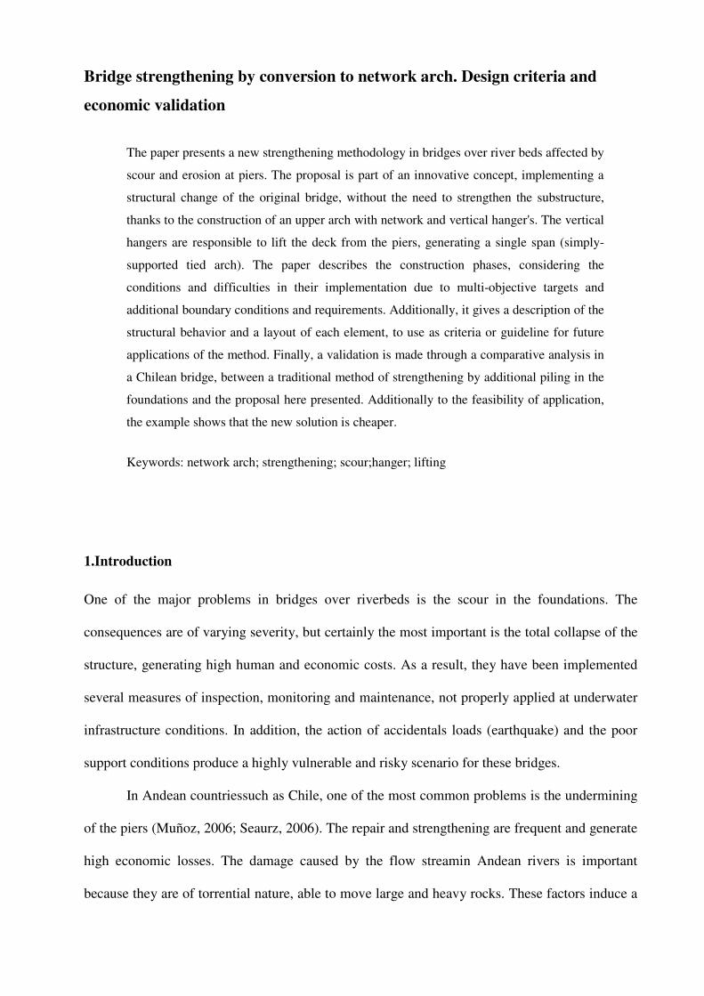
As mentioned before, it is recommended the use of symmetrical profiles of the arch (squares).
The connection of the hangers (vertical and network) is by welding a plate at the bottom of the
profile, joined by bolts between the plate and the end of the hanger (Figure 7).
Figure7. Connection: arch-hanger.
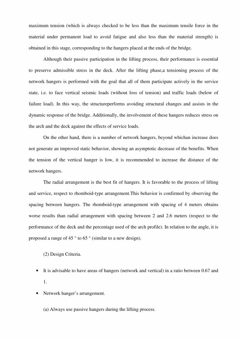
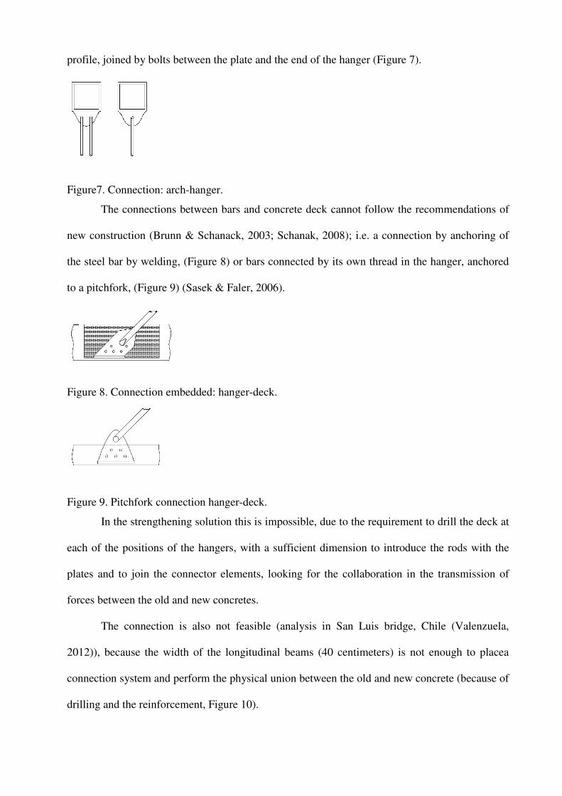
The connections between bars and concrete deck cannot follow the recommendations of
new construction (Brunn & Schanack, 2003; Schanak, 2008); i.e. a connection by anchoring of
the steel bar by welding, (Figure 8) or bars connected by its own thread in the hanger, anchored
to a pitchfork, (Figure 9) (Sasek & Faler, 2006).
Figure 8. Connection embedded: hanger-deck.
Figure 9. Pitchfork connection hanger-deck.
In the strengthening solution this is impossible, due to the requirement to drill the deck at
each of the positions of the hangers, with a sufficient dimension to introduce the rods with the
plates and to join the connector elements, looking for the collaboration in the transmission of
forces between the old and new concretes.
The connection is also not feasible (analysis in San Luis bridge, Chile (Valenzuela,
2012)), because the width of the longitudinal beams (40 centimeters) is not enough to placea
connection system and perform the physical union between the old and new concrete (because of
drilling and the reinforcement, Figure 10).

Figure10. Strengthened connection: hanger-deck.
For this reason, it is proposed a system similar to the KarolienenBridge (Unterweger,
2008), where the bar goes through the concrete element, connecting with a horizontal plate
located below the longitudinal support beams. The position of the rods depends on the
eccentricity between them (Figure 11).For the inclined hangers, the connection is located at each
side of the girder, passing through the slab with a penetration equal to the length defined by each
hanger slope. For that reason the depth of the drilling is equal to the thickness of the slab plus the
projection of the slope. Then the hanger follows the longitudinal girder from the bottom of the
slab reaching the bottom flange tied to the sides of the girder. Finally when arriving to the flange,
it is joined to a plate (bolted), providing the support to the girder and the hanger.
Figure11.Proposed connection: hanger-deck.
The same system is considered for tensioning the vertical hangers. However, the
application of these hangers requires additional work because of their location in the area where
the beam rests on the pier. For this reason, during the construction process, when un-linking the
beam from the pier, it is necessary to carry out a cut in the pier in the points of support of the
longitudinal beams (if the gap between pier and transverse beam is small). In this position,
vertical jacks are placed (the same that are subsequently used for the replacement of bearing
devices in the abutments), applying a controlled force to enable increase the gap to place the
lower plate and fix the bar (Figures12 and Figure 13).

Figure 12. Lifting mechanism to placed the hangers.
Figure 13. Final scheme: placed the hangers.
As a summary, Table 1 presents some of the design criteria previously analyzed.
Table 1.Element characteristic criteria
Elements Strengthened bridge
Arch
Position One centered (deck< 8m)
Double (deck > 8m)
Inclination No
Bracing Vierendeel
Layout Circular
Rise/span ratio 16-17%
Profile Square
Size Profile/Length < 1/127
Network
Hangers
Type of hangers 2
N° of groups 3
Distribution Radial - Vertical
Distance hangers 2 to 3 meters
Angle 55° a 65°
Deck
Material Concrete reinforcement
Type Long. &Transv. Beams

Increase high Transversal beam
Use transversal beam Yes
Bearings
Model Support Simple support
Type Pot Bearing
N° devices Original support
Connection
Connection Coupling hanger No
Arch-hanger Connection plate and screw
Hanger-deck Bar with inferior plate
Active hanger-deck Bar with special inferior plate
Arch-deck
Double plate embedment
+ exterior prestress
Verified pinned alternative
4. Economic validation
The San Luis road bridge, Chile (Figure 14) was used to perform an economic cost comparison
between the traditional and new proposed strengthening methods. . The bridge is composedof a
cross-section with three continuous beams and a reinforced concrete slab (Figure 15).
Diaphragms (transversal beams) are provided over the piers, abutments and at mid-span of each
span. The deck is supported on three wall-piers, generating four spans (13.5 - 16.5 meters)
covering a total length of 60 meters.
Figure 14. General view San Luis Bridge.
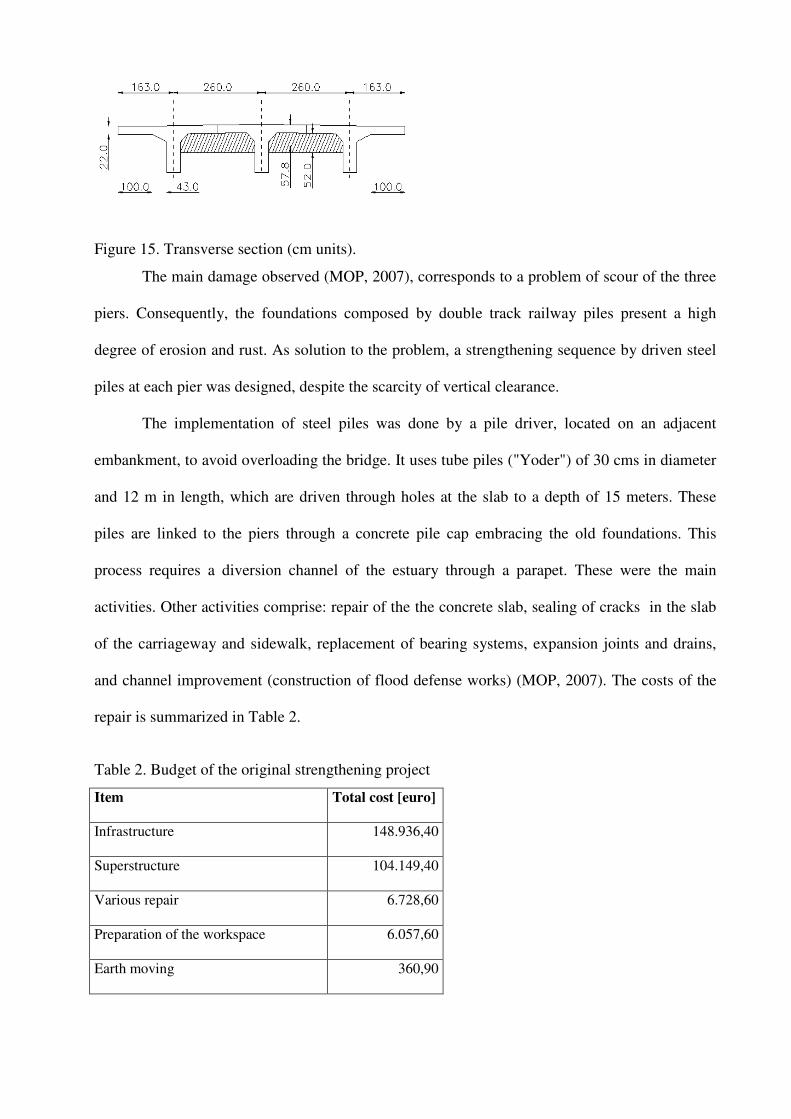
Figure 15. Transverse section (cm units).
The main damage observed (MOP, 2007), corresponds to a problem of scour of the three
piers. Consequently, the foundations composed by double track railway piles present a high
degree of erosion and rust. As solution to the problem, a strengthening sequence by driven steel
piles at each pier was designed, despite the scarcity of vertical clearance.
The implementation of steel piles was done by a pile driver, located on an adjacent
embankment, to avoid overloading the bridge. It uses tube piles ("Yoder") of 30 cms in diameter
and 12 m in length, which are driven through holes at the slab to a depth of 15 meters. These
piles are linked to the piers through a concrete pile cap embracing the old foundations. This
process requires a diversion channel of the estuary through a parapet. These were the main
activities. Other activities comprise: repair of the the concrete slab, sealing of cracks in the slab
of the carriageway and sidewalk, replacement of bearing systems, expansion joints and drains,
and channel improvement (construction of flood defense works) (MOP, 2007). The costs of the
repair is summarized in Table 2.
Table 2. Budget of the original strengthening project
Item Total cost [euro]
Infrastructure 148.936,40
Superstructure 104.149,40
Various repair 6.728,60
Preparation of the workspace 6.057,60
Earth moving 360,90

Drainage and protection of the deck 9.607,90
Controls and security elements 15.195,40
Additional works 31.774,40
Environmental measures 2.958,60
Works in the riverbed 54.311,40
Industrial benefit (6 %) 27.137,80
Indirect cost (13 %) 58.798,50
19% VAT (Value Added Tax) 88.543,20
The total cost of the implemented repair was 554.560 Euros.
The alternative strengthening through tied arch includes some activities similar to the
original project, specifically associated with repairs to the superstructure and additional
activities. On the other hand, the biggest change is associated with the reduction intervention in
the infrastructure, avoiding changes in the riverbed. Thus, based on the presented criteria, the
strengthening of the bridge was designed with the following solution: s a single centered arch
with a square profile with dimensions 75x75x3,6 centimeters, the use of 26 network hangers and
three active vertical hangers (one over each pier). Furthermore, it includes a widening and
strengthening of the deck road according to the current bridge regulations in Chile. The complete
design is available in Valenzuela (2010). The predicted budget for this alternative solution is
presented in Table 3.
Table 3. Budget of the new strengthening project
Item Total cost [euro]
Infrastructure 5.394,83
Superstructure 12.745,16
Various repair 4.419,60
Preparation of the workspace 3.695,88

Earth moving 183,60
Control and security elements 49.776,94
Environmental measures 2.958,61
new strengthening at superstructure 236.292,72
Industrial benefit (6 %) 18.928,00
Indirect cost (13 %) 41.010,80
19% VAT (Value Added Tax) 71.327,20
The total budget obtained corresponds to 446.734 Euros.
The proposed project is economically feasible, with a budget of 20% less than the
original project, showing this new methodology as a feasible alternative to traditional
strengthening.
Besides this difference on construction budgets may bealradyconsidered as relevant
enough to propose the alternative strengthening solution, we should take into account additional
benefits, some of them not easy to deal with in economic terms, as:
1.- The alternative solution considers an improvement (widening) of the deck, avoiding
actual traffic limitations and enhancing safety to the users
2.- The elimination of the piers, will avoid future under water inspections, reducing the
life-cycle cost of the bridge. Additionally, the vulnerability of the bridge to scour and seismic
hazards will decrease which will translate in reduced feasibility of bridge closure and therefore
in less expected user costs from a life-cycle cost perspective. By contrast, future inspection lines
will be focused on the hanger system maintenance and corrosion of the metallic elements.
3.- The arch solution will completely eliminate the scour problem and therefore the
necessity of any repetitive and expensive additional repair work in the future, thus decreasing the
total expected maintenance and repair costs.

4.- The aesthetics of the proposed alternative is much more enhanced compared to the
original bridge.
In summary, the total cost from a life-cycle cost perspective will be much lower for the
proposed strengthening solution.
6. Conclusions.
It has been presented and verified the feasibility of a new method of strengthening of bridges
with scour problems at piers. The method attempts to eliminate the problem by lifting the deck
from the original piers and support it with an upper arch, using the original deck (supplemented
with an external post-tensioning) as a tied element of the arch system. This allows to eliminate
the original piers.
The method requires the incorporation of steel arches, with an arrangement of vertical
hangers responsible to lift the deck by jacking, and an arrangement of network hangers to
modulate the stress states, providing stability in the lifting stages and improving the in-service
performance to asymmetric loads.
The method is defined with a minimum of three construction phases: preparation
(placement of elements), lifting (active stressing of vertical hangers) and network (tensioning of
the network hangers to allow optimal in-service conditions).
The design criteriais controlled by the requirement to keep the stress state in the deck as
close as possible to the original condition of the deck (a continuous beam). Thiscontrols the
design of other elements and avoids possible failure of the structure. Therefore, the arch becomes
the primary design parameter. Similarly, the study of vertical tensioning of the hangers (both in
value of the tension force and the order of tensioning) is fundamental to obtain an efficient
solution.
The design criteria derives on a set of condition to the arch and the hangers. First of all,
the arch profile is higher than in the case of a new network arch. In the case ofthe hangers, it is

recommended a close relationship of areas between vertical and network hangers. The multi-
objective optimization problem seeking to obtain the optimal tension in each hanger and order of
tensioning is derived by a genetic algorithm.
The conditions at the longitudinal edges of the deck require a particular study on the joint
between arch and deck.
The application of the method to the San Luis Bridge confirms that this strengthening
technique is economically sustainable, durable and improves the bridge aesthetics. In the paper,
the method is applied to a reinforced concrete bridge composed of longitudinal beams and upper
slab. However, the methodology can be easily extended to composite (steel+concrete) bridge
decks and also to slab and box-girder concrete bridges. The main limitation could be the
dimensions of the cross-section and the total length of the bridge after the removal of the original
piers.
7.References
Brunn, B. &Schanack F. (2003), "Calculation of a double track railway network arch bridge
applying the European standards".Diploma Thesis, TechnischeUniversitat Dresden,
Germany
Goldberg, D.E. (2002) “ The design of innovation: lesson from and for competent genetic
algorithms”. Ed. Kluwer Academic, Boston, USA
Malerba, P.G. (2014) “Inspecting and repairing old bridges: experiences and lessons”. Structure
and Infrastructure Engineering, 10:4, 443-470
MOP (2007). Informe de Estructuras “Reparacion Puente San Luis” [Structure Reporte –
Strengthening of San Luis Bridge] (in Spanish). Ministerio de Obras Públicas de Chile,
Direccion de Vialidad Santiago, Chile.
Muñoz, E. & Valbuena, E. (2006), “Socavacion de puentes” [Scour of bridges] (in Spanish).
Infraestructura Vial, Vol. 8 N° 15, pp. 25-39.
Pircher, M., Stacha, M., Wagner, J. (2013) “Stability of network arch bridges under traffic
loading”. Proceedings of the Institution of Civil Engineers (ICE), Bridge Engineering,
166, BE3, 186-192.

Rongish, J. (2011) “Refuerzo del Puente Puangue en Chile mediante configuracion tipo network.
Comportamiento sismico” (in Spanish), Master Thesis, UniversitatPolitecnica de
Catalunya, Barcelona, Spain.
Sasek, L. & Faler, R. (2006) “Network Arch Bridge in Bechyne”, 6th International Symposium
on Steel Bridges, Prague, Czech Republic.
Schanack, F. (2008) Network Arch Bridges, Ph.D Thesis, University of Cantabria, ACHE.
Spain.
Seaurz, A. (2006) “Dimensionamiento hidraulico optimizado de puentes con terraplenes”,
Ph.D.Thesis (in Spanish). University of Piura, Peru.
Tveit, P. (2007) “The Network Arch. Bits of Manuscript after Lectures in 44 Countries” 140
pages. Retrieved from: http://pchome.grm.hia.no/~pchome/
Unterweger, H. (2008) “Remarkable Strengthening of an old Steel Highway Bridge”, Creating
and Renewing Urban Structures, 17th Congress of IABSE, Chicago, USA.
Valenzuela, M.A. (2010) “Refuerzo de puentes existentes por cambio de esquema estatico.
Aplicacion al puente San Luis en Chile” (in Spanish). Master Thesis,
UniversitatPolitecnica de Catalunya, Barcelona, Spain.
Valenzuela, M.A. & Casas, J.R. (2011) “Bridge strengthening by structural change: Optimization
via genetic algorithm”, Proceedings of the IABSE-IASS symposium, London, UK.
Valenzuela, M.A. (2012) “Refuerzo de puentes de luces medias mediante conversión en arco
atirantado tipo network” (in Spanish). Ph.DThesis, UniversitatPolitecnica de Catalunya,
Barcelona, Spain.
Valenzuela, M.A., Casas, J.R. (2013) “Refuerzo de puentes: método del arco atirantado. Estado
del arte y criterios de diseño” (in Spanish). Editorial Publicia. Saarbrücken (Germany).