bridge cont for ll part i_2011
DESCRIPTION
PCI Prestressed Bridge Design Example Part 1TRANSCRIPT

EXAMPLE 9.2 – Part IPCI Bridge Design Manual
EXAMPLE 9.2 – Part IPCI Bridge Design Manual
BULB “T” (BT-72)
THREE SPANS, COMPOSITE DECK
LRFD SPECIFICATIONS
Materials copyrighted by Precast/Prestressed Concrete Institute, 2011. All rights reserved. Unauthorized duplication of the material or presentation
prohibited.

BRIDGE LAYOUT - LongitudinalBRIDGE LAYOUT - Longitudinal
Continuous for Live Load
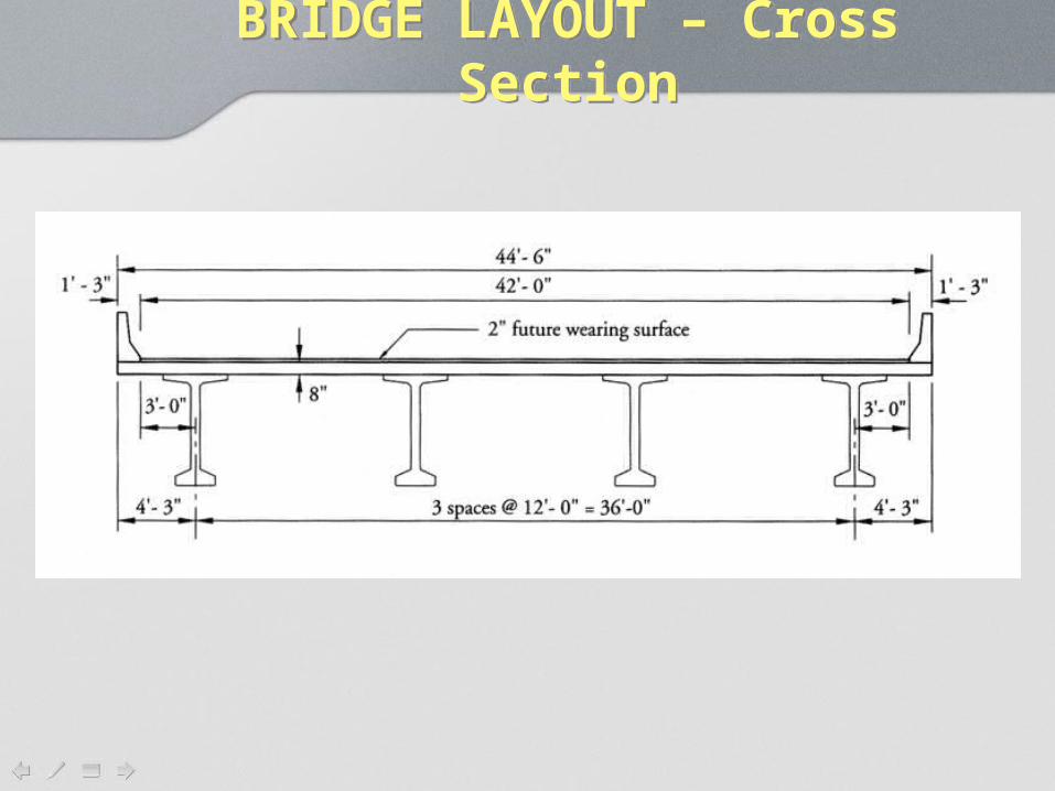
BRIDGE LAYOUT – Cross SectionBRIDGE LAYOUT – Cross Section

DESIGN SPECIFICATIONSDESIGN SPECIFICATIONS
• LRFD – 5th Edition (2010)• HL-93 Truck Loading• No Skew• Composite Deck

DESIGN SPECIFICATIONSDESIGN SPECIFICATIONS
• Concrete:– fc’ = 7.0 ksi @ 28 days
– fci’ = 5.5 ksi @ release
– wc = 0.150 kcf
– Ecb = 33000w1.5 (fc’)0.5 (LRFD 5.4.2.4)
= 33000(0.150)1.5(7.0)0.5 = 5072 ksi• Prestressing Steel:
– GR 270 (fpu = 270 ksi; fpy = 243 ksi)
– ½” strand (Ap = 0.153 in2 / strand)
– Ep = 28500 ksi

DESIGN SPECIFICATIONSDESIGN SPECIFICATIONS
• Mild Steel– GR 60 (fy = 60 ksi)– Es = 29000 ksi
• Future Wearing Surface– 2” thick– wws =0.150 kcf
• Barriers– New Jersey type– 0.300 k/ft

DESIGN SPECIFICATIONSDESIGN SPECIFICATIONS
• Deck– 7.5” Structural thickness– 0.5” wearing surface– Total thickness = 8”– fc’ = 4.0 ksi @ 28 days
– wc = 0.150 kcf
– Ecs = 33000w1.5 (fc’)0.5 (LRFD 5.4.2.4)
= 33000(0.150)1.5(4)0.5 = 3 834 ksi• Note – LRFD uses kip, inch, foot units
in formulae

CONTINUOUS FOR LL PRECAST BRIDGESCONTINUOUS FOR LL PRECAST BRIDGES
• Precast beams are made in a factory and shipped to site. The beam is set on simple supports – beam carries self weight and prestressing force as a simple beam.

CONTINUOUS FOR LL PRECAST BRIDGESCONTINUOUS FOR LL PRECAST BRIDGES
The deck is formed and poured. Since the beams are NOT shored, the beams carry the deck load as simple beams.

CONTINUOUS FOR LL PRECAST BRIDGESCONTINUOUS FOR LL PRECAST BRIDGES
The deck is cast continuous over the piers. When the deck hardens, a continuous structure is formed. The negative moment connection is usually made with non-prestressed steel over the piers. Thus, the negative moment region is conventionally reinforced.

CONTINUOUS FOR LL PRECAST BRIDGESCONTINUOUS FOR LL PRECAST BRIDGES
• Once the deck hardens and continuity is established, any superimposed dead load (asphalt surfaces, barriers, utilities) is carried by the beams as a continuous structure.
• All live load is carried as a continuous structure.

CONTINUOUS FOR LL PRECAST BRIDGESCONTINUOUS FOR LL PRECAST BRIDGES
• After the slab is poured, the beams will continue to creep and shrink; cambering up.
• Temperature will also cause camber.• Positive moments will form causing
cracking.

CONTINUOUS FOR LL PRECAST BRIDGESCONTINUOUS FOR LL PRECAST BRIDGES
• A positive moment connection is required. The requirements for this will be discussed later. (LRFD 5.14.1.4)

CONTINUOUS FOR LL PRECAST BRIDGESCONTINUOUS FOR LL PRECAST BRIDGES
• It is thought that creep and shrinkage will redistribute dead load, so some states design using simple spans for all dead load and assuming a continuous bridge for live load only.
• Some states completely ignore the continuity and design as simple span for all loads.

DESIGN SPANSDESIGN SPANS
• Beams:– Overall Length
• 110 ft. end spans• 119 ft center span
– Design Spans –Simple Span beam• 109 ft. end spans• 118 ft. center span
– Design Spans – Continuous Beam• 110 ft. end spans• 120 ft. center span
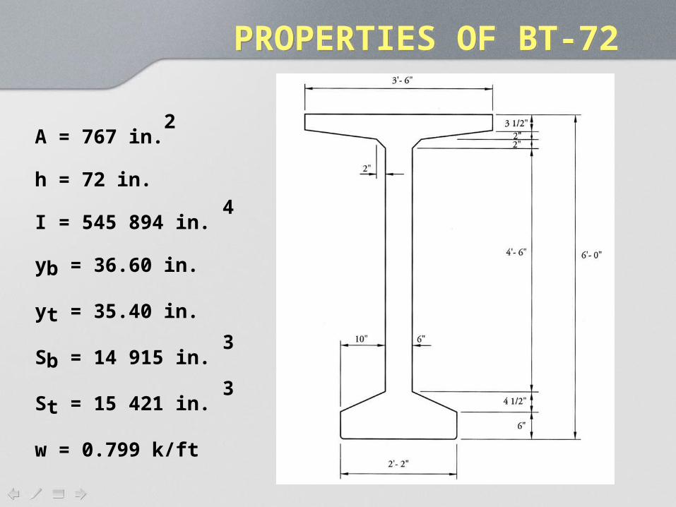
PROPERTIES OF BT-72PROPERTIES OF BT-72
A = 767 in.2
h = 72 in.
I = 545 894 in. 4
yb = 36.60 in.
yt = 35.40 in.
Sb = 14 915 in. 3
St = 15 421 in. 3
w = 0.799 k/ft

PROPERTIES OF COMPOSITE BT-72
PROPERTIES OF COMPOSITE BT-72
Ecs = 3834 ksi Ecb = 5072 ksi (prev. defined)
Modular ratio: n = Ecs /Ecb = 3834/5072 = 0.7559
LRFD 4.6.2.6.1 (NEW IN 2009):
The effective flange width is now the TRIBUTARY AREA:
bf = 144 inches

PROPERTIES OF COMPOSITE BT-72
PROPERTIES OF COMPOSITE BT-72
Note: ½ inch haunch
assumed.
Shaded area is transformed.

PROPERTIES OF COMPOSITE BT-72PROPERTIES OF COMPOSITE BT-72
Transformed Flange Width =
(Effective Flange Width)*n = 144(0.756)= 108.9 in.
Transformed Flange Area = 108.9”(7.5”) = 816.8 in2
Note: only 7.5” of deck thickness is structural.

PROPERTIES OF COMPOSITE BT-72
PROPERTIES OF COMPOSITE BT-72
Haunch – assumed ½” over BT-72 flange width to account for differential camber in the beams.
Transformed Haunch Width = 0.756(42”) = 31.75 in.
Transformed Haunch Area = 31.75”(0.5”) = 15.87 in2

PROPERTIES OF COMPOSITE BT-72PROPERTIES OF COMPOSITE BT-72Atr
in2
yb
in.
Ayb
in.3
A(ybc-yb)2
in.4
I in.4
I+A(ybc-yb) in.4
Beam 767.00 36.60 28072 325484 545894 871378
Haunch 15.87 72.25 1147 3601 0 3601
Deck 816.8 76.25 62280 296420 3829 300249
Sum 1599.7 91500 1175230
ybc = 91500/1599.7 = 57.20 in.
(distance to bottom of composite)

PROPERTIES OF COMPOSITE BT-72PROPERTIES OF COMPOSITE BT-72
Ac = 1599 in2
Ic = 1175230 in4
hc = 80 in.
ybc = 91477/1599.4 = 57.20 in.
(distance to bottom of composite)
ytc = 80 – 57.20 = 22.80 in.
(distance to top of composite)
ytg = 72 – 57.20 = 14.80 in.
(distance from composite neutral axis to top of beam)

PROPERTIES OF COMPOSITE BT-72
PROPERTIES OF COMPOSITE BT-72
Composite Section Modulus to Bottom:
Sbc = Ic / ybc = 1175230 /57.20 = 20545 in.3
Composite Section Modulus to Top of Composite:
Stc = Ic /nytc = 1175230/(0.756*22.8) = 68180 in.3
Note: 1/n converts stress in transformed concrete to stress in actual concrete.
Composite Section Modulus to Top of Beam:
Stg = Ic / ytg = 1175230 /14.8 = 79400 in.3

DEAD LOADS - DCDEAD LOADS - DC
DC – Applied to precast only.
Beam self weight wg = 0.799 kip/ft.
Slab weight – include ½” integral wearing surface.
ws = (8”/12”/ft)(12 ft.)(0.150 kcf) = 1.20 kip/ft
Haunch
wh = (0.5”/12)(42”/12)(0.150 kcf) = 0.022 kip/ft
DEAD LOADS - DCDEAD LOADS - DC
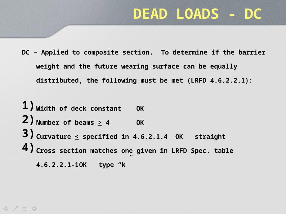
DC – Applied to composite section. To determine if the barrier weight and the
future wearing surface can be equally distributed, the following must be met
(LRFD 4.6.2.2.1):
1) Width of deck constant OK
2) Number of beams > 4 OK
3) Curvature < specified in 4.6.2.1.4 OK straight
4) Cross section matches one given in LRFD Spec. table 4.6.2.2.1-1 OK type
“k”

k

DEAD LOADS - DCDEAD LOADS - DC5) The overhang of the roadway, from the outside of the web, de < 3.0 ft.
de = 3 ft OK
Def. of de changed in
2008 interim (LRFD 4.6.2.2.1).
DEAD LOADS - DCDEAD LOADS - DC
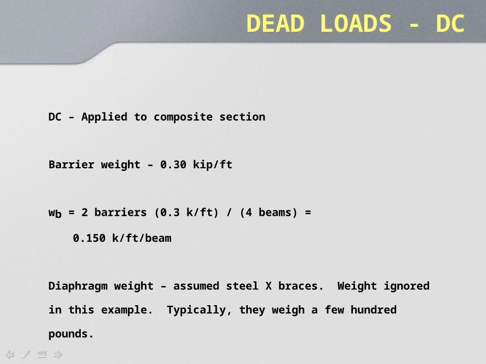
DC – Applied to composite section
Barrier weight – 0.30 kip/ft
wb = 2 barriers (0.3 k/ft) / (4 beams) =
0.150 k/ft/beam
Diaphragm weight – assumed steel X braces. Weight ignored in this
example. Typically, they weigh a few hundred pounds.

DEAD LOADS - DWDEAD LOADS - DW
DW – Future wearing surface and utilities.
Future wearing surface 2” @ 0.150 kcf
(2”/12)(0.150 kcf) = 0.025 ksf
0.025 ksf (42’ roadway width) / 4 beams
= 0.263 k/ft /beam

UNFACTORED DEAD LOADS UNFACTORED DEAD LOADS
All loads are uniform. DL moments and shears on the precast can be found
from:
0.5
0.5x
x
V w L x
M wx L x
Use overall length at initial (release) condition.
Center to center of bearing at deck placement.

UNFACTORED DEAD LOADSUNFACTORED DEAD LOADS
The shears and moments due to the future wearing surface and the barrier
weight are computed by considering the bridge as a continuous, three span
structure.
The span lengths after continuity is established are center of support to center
of pier for end spans and center of pier to center of pier for the middle span.
Shears and moments can be found using any analysis program or by a hand
calculation.

Unfactored DL MomentsUnfactored DL Moments
End Spans
Middle
Span

LIVE LOAD DISTRIBUTION FACTORSLIVE LOAD DISTRIBUTION FACTORS
To use distribution factors, the following must be met:
1) Width of deck constant OK
2) Number of beams > 4 OK
3) Curvature < specified in 4.6.2.1.4 OK straight
4) Cross section matches one given in LRFD Spec. table 4.6.2.2.1-1 OK
type “k”
5) de < 3 ft. OK 3 ft.
6) Beams parallel and approximately same stiffness. OK

LIVE LOAD DISTRIBUTION FACTORS - MOMENT
LIVE LOAD DISTRIBUTION FACTORS - MOMENT
Number of design lanes = integer part of
42 ft. / (12 ft./lane) = 3 lanes
42 ft. is clear roadway width.
Interior Beams (Table 4.6.2.2.2b-1):
0.10.6 0.2
3
0.10.4 0.3
3
0.0759.5 12
0.0614 12
g
s
g
s
Two Lanes
KS SDFM
L Lt
One Lane
KS SDFM
L Lt

LIVE LOAD DISTRIBUTION FACTORS - MOMENT
LIVE LOAD DISTRIBUTION FACTORS - MOMENT
To use these factors:
1) 3.5’ < S < 16’ S = 12 ft. OK
2) 4.5” < ts < 12” ts = 7.5 in. OK
3) 20’ < L < 240’ L = 120 ft. OK
4) Nb > 4 beams Nb = 4 beams OK
Note: Although this is a 3 lane bridge, there is NO reduction to the LL for
multiple presence. The distribution factors already account for multiple
presence.

LIVE LOAD DISTRIBUTION FACTORS - MOMENT
LIVE LOAD DISTRIBUTION FACTORS - MOMENT
2g g
c
cs
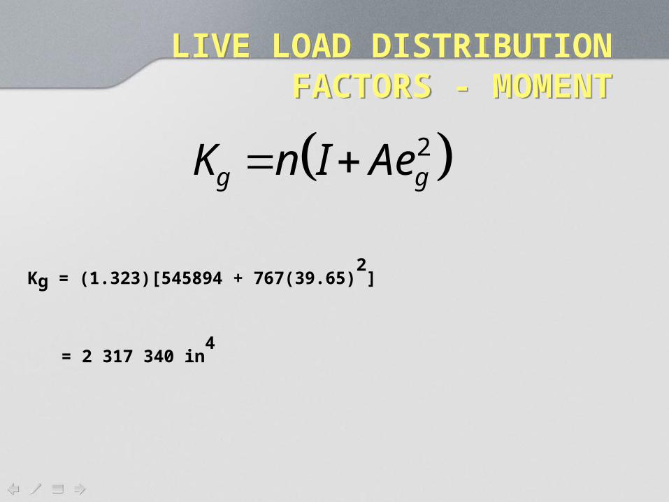
K n I Ae
En
E
n = 5072/3834 = 1.3229
eg = (7.5/2)+0.5+35.4 = 39.65
= distance between centroids of beam and slab
A = area of non-composite beam
I = moment of inertia of non-composite beam
LIVE LOAD DISTRIBUTION FACTORS - MOMENT
LIVE LOAD DISTRIBUTION FACTORS - MOMENT
2g gK n I Ae
Kg = (1.323)[545894 + 767(39.65)2
]
= 2 317 340 in4

LIVE LOAD DISTRIBUTION FACTORS - MOMENT
LIVE LOAD DISTRIBUTION FACTORS - MOMENT
0.10.6 0.2
30.0759.5 12
g
s
Two Lanes
KS SDFM
L Lt
S = 12 ft.
L = 120 ft.
Kg = 2 317 340 in4
ts = 7.5”
DFM = 0.905 lanes/beam

LIVE LOAD DISTRIBUTION FACTORS - MOMENT
LIVE LOAD DISTRIBUTION FACTORS - MOMENT
0.10.4 0.3
30.0614 12
g
s
One Lane
KS SDFM
L Lt
S = 12 ft. L = 120 ft.
Kg = 2 317
340 in4
ts = 7.5”
DFM = 0.596 lanes/beam
DFM = 0.905 lanes/beam –two lanes CONTROLS

LIVE LOAD DISTRIBUTION FACTORS - SHEAR
LIVE LOAD DISTRIBUTION FACTORS - SHEAR
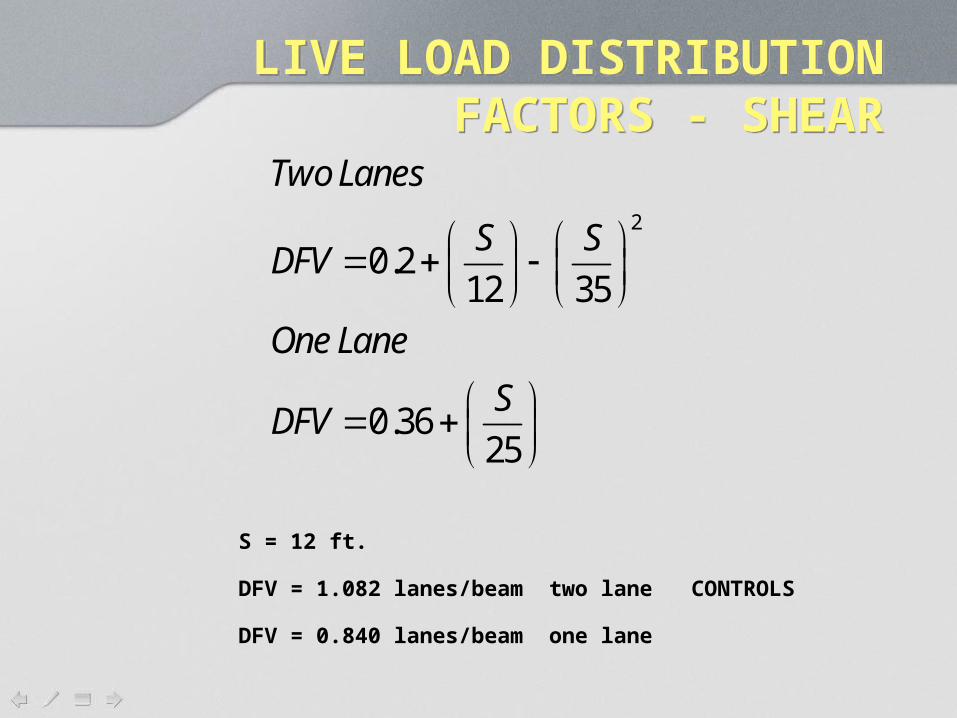
2
0.212 35
0.3625
Two Lanes
S SDFV
One Lane
SDFV
Interior Beams:

LIVE LOAD DISTRIBUTION FACTORS - SHEAR
LIVE LOAD DISTRIBUTION FACTORS - SHEAR
To use these factors:
1) 3.5’ < S < 16’ S = 12 ft. OK
2) 4.5” < ts < 12” ts = 7.5 in. OK
3) 20’ < L < 240’ L = 120 ft. OK
4) Nb > 4 beams Nb = 4 beams OK
5) 10 000 < Kg < 7 000 000
Kg = 2 317 340 OK
LIVE LOAD DISTRIBUTION FACTORS - SHEAR
LIVE LOAD DISTRIBUTION FACTORS - SHEAR
2
0.212 35
0.3625
Two Lanes
S SDFV
One Lane
SDFV
S = 12 ft.
DFV = 1.082 lanes/beam two lane CONTROLS
DFV = 0.840 lanes/beam one lane