brian s. ensign, rcdd/nts/osp, csi director – national ... optic connectors... · leviton...
TRANSCRIPT

Fiber Optic ConnectorsBasics, Styles, Trends
Brian S. Ensign, RCDD/NTS/OSP, CSIDirector – National Accounts & Specification Sales
Leviton Manufacturing Company
BICSI North East Regional MeetingMarch 01, 2007

Agenda
History and Market
Standards
Construction and Fiber Types
– Connector typical components
Performance Definitions and Measurement
Connector Types
Applications
– Future

History
1965 - Charles K. Kao and George A. Hockham of the British company Standard Telephones and Cables demonstrated that optical fiber could be a practical medium for communication, if the attenuation could be reduced below 20 dB per kilometer
1970 - Researchers Robert D. Maurer, Donald Keck, Peter Schultz, and Frank Zimar working for American glass maker Corning Glass Works. They manufactured a fiber with 17 dB optic attenuation per kilometer by doping silica glass with titanium.
1977 - On April 22, General Telephone and Electronics sent the first live telephone traffic through fiber optics, at 6 Mbit/s, in Long Beach, California.
1986 - The erbium-doped fiber amplifier, which reduced the cost of long-distance fiber systems by eliminating the need for optical-electrical-optical repeaters, was invented by David Payne of the University of Southampton, and Emmanuel Desurvire at Bell Laboratories.
And the industry and applications have exploded since!!!

The Market
There are 110 design types of Fiber Optic connectors.
Total factory shipments of Fiber Optic connectors were $1.273 billion in 2005 and are projected to reach $1.976 billion by theyear 2010.
Copyright © 2006, Fleck Research, Global Connector Research Group, Inc.

Connector Standards
TIA/EIA-4750000-B Generic Specification for Fiber Optic Connectors
TIA/EIA-604 Fiber Optic Connector Intermateability Standards (FOCIS)
TIA/EIA-568-B.3 / C.0 / C.3Commercial Building Fiber Optic Standards
www.tiaonline.org

Connector Standards
GR-326 Generic Requirements for Single-Mode Optical Fiber Connectors
GR-1435 Generic Requirements for Multi-fiber Optical Connectors
www.telcordia.com

Key IEEE Standards and media for 10 Gigabit Ethernet
IEEE Ethernet protocol standard 802.3 for Carrier Sense Multiple Access with Collision Detection (CSMA/CD) Access Method and Physical Layer Specifications
IEEE standard 802.3ae for 10 Gigabit Ethernet over Optical Fiber (single-mode and multi-mode).
IEEE standard 802.3aq for 10 Gigabit Ethernet over installed multimode Optical Fiber up to 220 meters.

Key physical layer interfaces (PHY) and media
10GBASE-SR (”short range”) — designed to support short distances over deployed multi-mode fiber cabling, it has a range of between 26m - 550m depending on the bandwidth of the glass cores. Uses spectral wavelength at 850nm and typically VCSELs.
10GBASE-LX4 — uses wavelength division multiplexing to support ranges of between 240 m and 300 m over deployed multi-mode cabling. Also supports 10 km over single-mode fiber . Uses wavelength of 1310 nm.
10GBASE-LR (”long range”) — this standard supports distances of up to 10 km over single-mode fiber (using 1310 nm).

Key physical layer interfaces (PHY) – cont…
10GBASE-ER (”extended range”) — this standard supports distances up to 40 km over single-mode fiber (using 1550 nm). Recently several manufacturers have introduced 80-km-range ER pluggable interfaces.
10GBASE-LRM [1] — this standard will support distances up to 220 m 10 Gbit/s on FDDI-grade multi-mode cable. Various combinations of offset and center launch cables on both ends of the link. Very complex.
10GBASE-SW , 10GBASE-LW and 10GBASE-EW — These varieties use the WAN PHY, designed to interoperate with OC-192 / STM-64 SDH/SONET equipment using a light-weight SDH/SONET frame. They correspond at the physical layer to 10GBASE-SR, 10GBASE-LR and 10GBASE-ER respectively, and hence use the same types of fiber and support the same distances. (There is no WAN PHY standard corresponding to 10GBASE-LX4.)

The Glass
Typical Construction
Example: 8/125µm•Core 8 micron diameter•Cladding 125 micron diameter

The Glass
Single-mode – 8/125µm
Fiber supporting only one mode is called single-mode
Default Premises Cable Jacket Color = Yellow
Uses Lasers to transmit signal
The laser can be multiplexed in order to send many different signals down one fiber.
1310 and 1550nm are the most common wavelengths
Single-mode systems can send a signal much faster and for longer distance than multimode systems.

The Glass
Multimode - 62.5/125µm and 50/125µmFiber with large (greater than 10µm) core diameter is called multimode fiberDefault Premises Cable Jacket Color = Orange or Aqua (for laser optimized fibers)The first multimode fiber size was 100/140µm. These larger sizes are currently used for instrumentation applications. Uses LED’s to transmit signal
850nm and 1310nm are the most common wavelengthsLED’s can not be multiplexed
Primarily used in short distance communication (LAN)Less than 2km

Single-mode – Multimode Comparison

The Connector
Fiber optic connectors have traditionally been the biggest concern in using fiber optic systems.
Connectors were once unwieldy and difficult to use.
Connector manufacturers have standardized and simplified connectors greatly.
This increasing user-friendliness has contributed to the increase in the use of fiber optic systems
The sole purpose of a connector is to mate fiber-optic cable with minimal loss of light.
Connectors are designed for many different applications including telecommunications, local area networks, and harsh environments.
Connector Basics
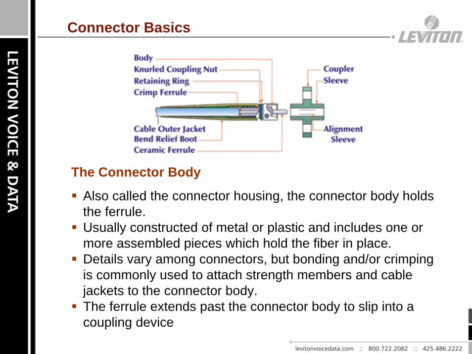
The Connector Body
Also called the connector housing, the connector body holds the ferrule. Usually constructed of metal or plastic and includes one or more assembled pieces which hold the fiber in place. Details vary among connectors, but bonding and/or crimping is commonly used to attach strength members and cable jackets to the connector body.The ferrule extends past the connector body to slip into a coupling device
Connector Basics
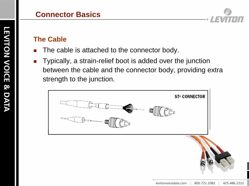
The CableThe cable is attached to the connector body. Typically, a strain-relief boot is added over the junction between the cable and the connector body, providing extra strength to the junction.

Connector Basics
The FerruleThe fiber is mounted in a long, thin cylinder, the ferrule, which acts as a fiber alignment mechanism. The ferrule is bored through the center at a diameter that is slightly larger than the diameter of the fiber cladding. The end of the fiber is located at the end of the ferrule.
Ferrules are typically made of metal or ceramic, but they may also be constructed of plastic.The most distinct differentiations between connector types are the diameter of the ferrule, 2.5 mm or 1.25 mm, and the type of polish.

Coupling of Connectors
The Coupling DeviceMost fiber optic connectors do not use the male-female configuration common to electronic connectors. Instead, a coupling device such as an alignment sleeve is used to mate the connectors.Similar devices may be installed in fiber optic transmitters andreceivers to allow these devices to be mated via a connector. These devices are also known as feed-through bulkhead adapters.

Performance Measures
Insertion Loss (IL) is the amount of optical power lost as a result of a connection. Expressed in decibels, it is the ratio of measured optical power before and after the connector. It always is tested because it is the most important connector parameter.
Return Loss (RL) a term applied to the light reflection in the connector’s interface that return to the source.
– The greater the absolute value, the better:
• Example: -60dB RL is better than -35dB RL.

Performance Measures
Back Reflection represents the total accumulated light reflected back to the source along a link. This return of the light is due to different physical phenomena such as multiple connector back-reflections, bad splicing, etc.Some effects of back reflection include the following:
– Less light is transmitted
– Causes interference with light source signals
– Creates higher bit error rate (BER) in digital systems
– Reduces signal-to-noise ratio (SNR) in analog systems
• CATV systems virtually standardize on APC type connectors
High back reflection can cause bad or harmful consequences such as:
– Causes fluctuations in the light source’s central wavelength
– Causes fluctuations in its output power
– Damages the light source (transmitter) permanently

Connector Loss
Connector loss is caused by a number of factors.
Loss is minimized when the two fiber cores are identical and perfectly aligned, the connectors are properly finished and no dirt is present.
Only the light that is coupled into the receiving fiber's core will propagate, so all the rest of the light becomes the connector loss.

Types of Polishes
The polish on a fiber connector dictates the amount of back reflection. Back reflection is a measure of the light reflected off the polished end of a fiber connector measured in negative dB. The physical-contact (PC) polish is a flat finish of the connecting areaThe angled physical contact (APC) is at an 8° angle. An APC greatly reduces back reflections caused by the physical interface.
Connector Styles
Anaerobic Adhesives: These connectors use a quick setting adhesive. They work well if your technique is repeatable, but often they do not have the wide temperature range of epoxies, so they are only used indoors. Thus, generally used for factory terminations only.
Epoxy/Polish: These connectors are the simple "epoxy/polish" type where the fiber is glued into the connector with epoxy and the end polished with special polishing film. These provide a very reliable connection with low losses. They can be factory or field installed.

Connector Styles
Crimp/Polish: Rather than glue the fiber in the connector, these connectors use a crimp on the fiber to hold it in. Early types offered "iffy" performance, but today they are pretty good, if you practice a lot. Expect to trade higher losses for the faster termination speed. And they are more costly than epoxy polish types.
Pre-Polished: Many manufacturers offer connectors that have a short stub fiber already epoxied into the ferrule and polished perfectly, so you just cleave a fiber and insert it like a splice. While it sound like a great idea, it has several downsides. First it is very costly, 2 to 3 times as much as an epoxy polish type. Second, you have to make a good cleave to make them low loss.

Connector Types – Biconic (FOCIS 1)
The Biconic connector was developed by AT&T and became the de facto standard for long haul telecommunications.
The Biconic connector features a cone-shaped tip, which holds a single fiber.
It is non-metallic, using polymer and epoxy in its construction.
Telcos have long since adopted other connectors, mainly the SC due to the drawbacks of the Biconic such as its large size and the fact that it is mated by screwing it into its coupling.
Screw coupling makes its performance sensitive to rotational changes.

Connector Types – ST (FOCIS 2)
ST stands for Straight Tip - a quick release style connector developed by AT&T. ST’s were the predominant connector in the late 80s and early 90s.
ST Connectors are among the most commonly used fiber optic connectors in networking applications. They are cylindrical withtwist lock coupling, 2.5mm keyed ferrule.
The ST connector has a bayonet mount and a long cylindrical ferrule to hold the fiber. Because they are spring-loaded, you have to make sure they are seated properly. If you experience high light loss, try reconnecting.

Connector Types – SC (FOCIS 3)
The SC (subscriber connector) was developed by NTT specifically as a telecom connector.
It features push-pull coupling which eliminates rotation which can damage fiber end-faces. This design also allows higher packaging densities.
An important element of the design is an isolated ferrule, which protects the ferrule and fiber from cable stresses.
The SC is available in the usual simplex configuration and with duplex adapters as well.
For maximum density, quad and "six-pack“ configurations are available.

Connector Types – FC (FOCIS 4)
FC stands for Ferrule Connector or Fixed Connection.
The FC connector was developed by NTT as a singlemode telecom connector.
It uses a combination of thread (screw-on) and keyed design to provide high repeatability and good fiber endfaceprotection.

Connector Types – MTP/MPO (FOCIS 5)
The MPO connector family is defined by two different standards. Internationally the MPO is defined by IEC-61754-7. In the USA, the MPO is defined by TIA-604-5 (FOCIS 5).
The MTP multi-fiber connector is US Conec’s trademarked name for their MPO connector.
The MTP connector is fully compliant with both FOCIS 5 and IEC-61754-7; therefore it is an MPO connector.
The MTP connector design is distinctly different than the MPO.
The MTP connector is a high performance MPO!
The MTP/MPO is a connector manufactured specifically for a multifiber ribbon cable.
MPO = Multi-fiber Push On

Connector Types – MTP/MPO (FOCIS 5)
Internal Components Comparison
MTP MPO
MTP recessed metal pin clamp and oval spring.
More clearance between spring and fiber ribbon.
MPO plastic pin clamp and round
spring.
The spring is not constrained and may damage the
ribbon.

Connector Types – MTP/MPO (FOCIS 5)
Connector Guide Pins - Durability Results Comparison
MTP Guide Pin (Elliptical) MPO Guide Pin (Sharp Chamfer)
Sharp edges…not goodSharp edges…not good
MTP guide hole damage after 600 matings
Typical MPO guide hole damage after 500 matings

Connector Types – LC (FOCIS 10)
LC The LC is a small form-factor (SFF) fiber optic connector.The LC connector uses a 1.25 mm ferrule, half the size of the ST. Otherwise, it is a standard ceramic ferrule connector. The LC has good performance and is highly favored for singlemode and LO Multimode and has been gaining the preference of equipment manufacturers because of its compact size and performance.

Connector Types – MTRJ (FOCIS 12)
The MTRJ (Mechanical Transfer Registered Jack)is a small form-factor duplex connector with both fibers in a single polymer ferrule. It uses pins for alignment and has male and female versions. It is multimode only.
The MTRJ connector resembles the RJ-45 connector used in Ethernet networks. The MTRJ was designed by AMP, but was later standardized as FOCIS 12 (Fiber Optic Connector Intermateability Standards) in EIA/TIA-604-12.

Connector Types – MU (FOCIS 17)
MU is a small form factor SC.
It has the same push/pull style, but can fit 2 channels in the same footprint of a single SC.
MU was developed by NTT.
The MU connector looks a miniature SC with a 1.25 mm ferrule.
Currently it is a popular connector type in Japan.

Other Connectors
SMA, D4, Mini-BNC, FDDI, ESCON, SCDC (Corning), Opti-Jack (Panduit), VF-45 (3M Volition), E2000 / LX.5, ....
Proprietary – No License Available
Old / Never adopted by equipment manufactures
No wide spread acceptance in the market

Applications
Pre-polished Adhesive Mechanical
Enterprise (indoors)
Outside Plant X X
Harsh Environments (Industrial) X X
Patch Cords X X
Fiber Types MM and SM MM and SM MM and SM
ReusableLimited (only
once)No
Virtually unlimited
Fast Installation Best Slow Medium
Craft Sensitiveness Lowest Medium/High Highest
Connector Types SC, ST SC, ST, LC, FC SC, ST, FC

Applications / Trends
Private Networks (Enterprise)– Small to Medium Networks
• ST, SC are predominant– Large Networks
• ST, SC with LC growing rapidly– Data Centers
• LC and MTP dominatePublic Networks (Service Providers)– Telcos
• SC with LC growing due to density– CATV
• FC, SC

Future
Higher performance
– 10gig, 40gig, 100gig
Greater density (Data Centers)
OSP Capable (FTTH networks)
FTTx Advancements
– Fiber to the Home
– Fiber in the Home
– Fiber to the Wall Plate
– Fiber to the Desk
Demand for ease of use, greater durability and repeatable performance over time will drive connector
technology!!!
