breeze embedded computing client€¦ · ..an embedded design lab 2 disclaimer this manual has been...
TRANSCRIPT

..an embedded design lab
1
Breeze Embedded Computing
Client
User’s Guide
Aug 2014

..an embedded design lab
2
Disclaimer
This Manual has been reviewed and validated for accuracy. The descriptions it contains are accurate for Breeze Embedded Computing Client. Breeze Innovation Pvt Ltd assumes no liability for damages incurred directly or indirectly from errors, omissions or discrepancies that may appear in this manual including the product and the software described in it. It may also be noted that this Manual is subject to change without notice.
Trademarks All Trademarks and Brand names appearing in this Manual may or may not be Registered Trade Marks or Brand names of the respective companies and are used only for identification and explanation to the benefit of the user.

..an embedded design lab
3
INTORDUCTION .................................................................................................................................... 4 INSTALLATION ..................................................................................................................................... 5
2.1 ECC Checklist .................................................................................................................................. 5 2.2 General Conditions and Precautions ................................................................................................. 5 2.3 Installing the ECC. ............................................................................................................................ 5
3 BREEZE ECC CONFIGURATION ...................................................................................................... 6 3.1 Breeze ECC Booting ......................................................................................................................... 6 3.2 Invoking Setup Utility: ..................................................................................................................... 8 3.3 Setup utility ....................................................................................................................................... 8
4 USER CONFIGURATION ................................................................................................................. 22 4.1 UTS User Configuration ................................................................................................................. 22 4.2 PRS User Configuration ................................................................................................................. 23 4.3 Vt320 User Configuration .............................................................................................................. 24
4.3.1 Configure a New Profile ........................................................................................................ 25 4.3.2 Modifying a profile ............................................................................................................... 28 4.3.3 Removing a profile ................................................................................................................ 31 4.3.4 Viewing a profile ................................................................................................................... 32 4.3.5 Activate a profile .................................................................................................................. 33
4.4 sybuts user ...................................................................................................................................... 33 4.5 root user .......................................................................................................................................... 33
5 Log off ........................................................................................................................................................ 34 Reboot..................................................................................................................................................... 35 CALCULATOR ..................................................................................................................................... 36 SERIAL PORT (RS-232 DE9) PIN OUT .............................................................................................. 37 PARALLEL PORT INTERFACE .......................................................................................................... 38

..an embedded design lab
4
INTORDUCTION
Unreserved ticketing constitutes the major ticketing requirement of Indian Railways. The Embedded Computing Client ECC is a Thin Client based unreserved ticketing system developed to address this requirement with the following objectives.
Computerized unreserved tickets
Computerized Tickets for MST/QST and platform tickets
Centralized Accounting
Centralized database and system administration
Centralized software release/ upgrades
This manual is intended for the users of ECC and provides the information needed to install and operate the ECC. Screenshots have been used wherever possible to improve understablity.

..an embedded design lab
5
INSTALLATION This chapter provides instructions to install and turn on ECC. Perform each step in order.
2.1 ECC Checklist
The ECC comes with the following items. Unpack the carton box and Check to make sure that you have the following items.
i. ECC (Thin Client) ii. Mouse iii. Mouse Pad iv. Universal AC Adapter and power card v. User's Manual CD.
2.2 General Conditions and Precautions
Make sure there is adequate space around the ECC for proper ventilation. Make sure the AC power cord connect to a grounded AC outlet, which is closer to ECC and easily accessible. Keep the ECC free of dust, moisture and exposure to direct Sun light. Keep the ECC away from heat sources such as heater. Position the ECC , Monitor and keyboard such that the system is ergonomically accessible to the user. Do not use ECC near liquids or corrosive chemicals. Do not place ECC near objects that create strong magnet fields.
2.3 Installing the ECC.
Place the Thin Client box, Monitor and Keyboard on a level surface. Connect the keyboard to the Thin Client box to a USB port on the unit. Connect the Mouse to a USB port on the unit. Connect the Power adaptor to Thin Client unit. Connect the LCD Monitor’s video cable to the Thin Client unit. Connect the power cord of the Monitor to the AC power out let. Connect the power cord of the Thin Client Unit to the AC power out let. Switch on the Monitor. Switch on the Thin Client. The Power on Indicator located on the front will glow. You can see the boot message on the screen and the led’s on the keyboard will blink. Adjust the brightness and contrast of the Monitor to the desired intensity. Adjust the Monitor such that the screen is at the desired viewing angle. Use a RJ45 patch cord to connect the Thin Client unit to the local LAN. Use the parallel printer cable provided with the parallel printer to connect to the parallel port on the unit, if parallel printer is used. Use a serial printer cable to connect the Serial printer to the COM2 port on the unit, if serial printer is used.

..an embedded design lab
6
3 BREEZE ECC CONFIGURATION
3.1 Breeze ECC Booting
When the thin-client is switched on the Breeze booting appears on the screen.
..an embedded design lab
7
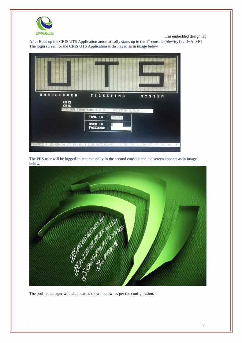
After Boot-up the CRIS UTS Application automatically starts up in the 1st console (/dev/tty1) ctrl+Alt+F1
The login screen for the CRIS UTS Application is displayed as in image below
The PRS user will be logged-in automatically in the second console and the screen appears as in image
below,
The profile manager would appear as shown below, as per the configuration.

..an embedded design lab
8
The profile gets automatically connected to the configured Server
3.2 Invoking Setup Utility:
By logging in as root user and typing ‘setup’ in the command prompt as shown below the setup utility can be invoked.
Bash-3.00# setup
3.3 Setup utility
Enter the setup password to enter in to the Setup Menu to configure thin-client.The default password is set to “setup123”. Password Menu:
..an embedded design lab
9
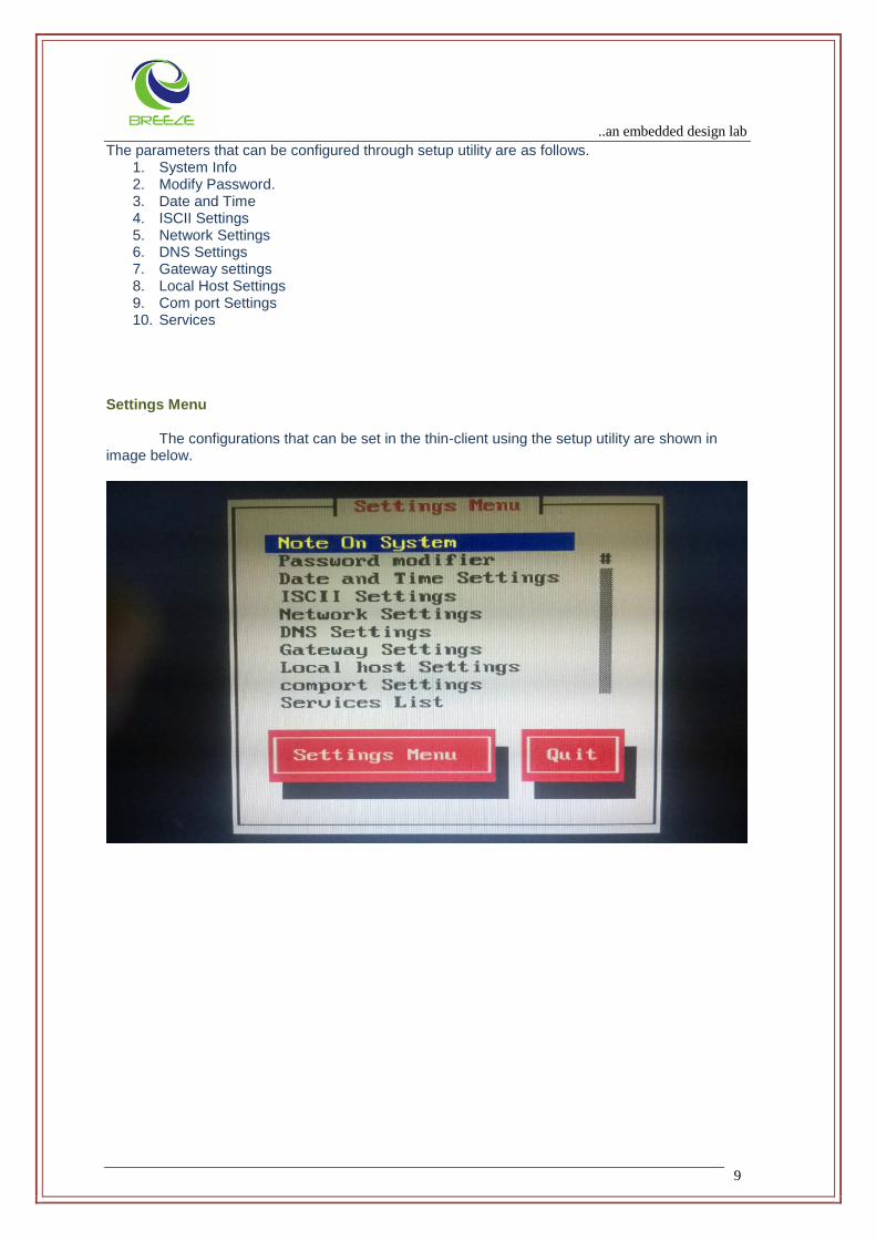
The parameters that can be configured through setup utility are as follows. 1. System Info 2. Modify Password. 3. Date and Time 4. ISCII Settings 5. Network Settings 6. DNS Settings 7. Gateway settings 8. Local Host Settings 9. Com port Settings 10. Services
Settings Menu
The configurations that can be set in the thin-client using the setup utility are shown in
image below.
..an embedded design lab
10
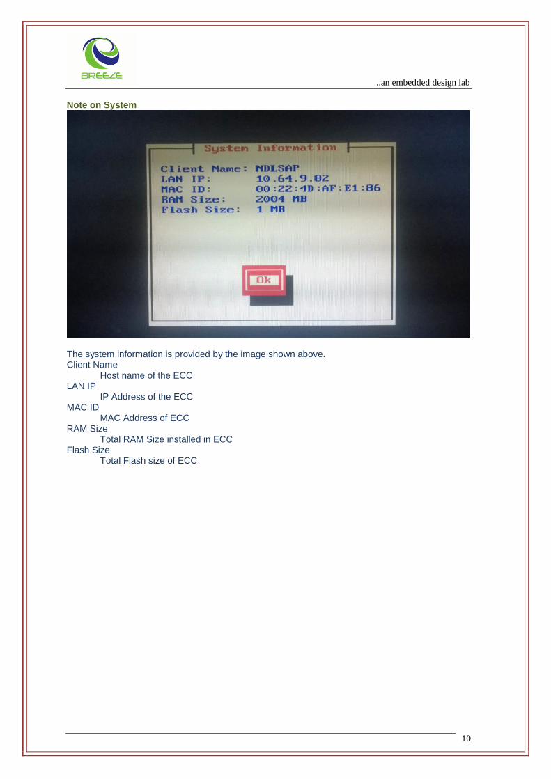
Note on System
The system information is provided by the image shown above. Client Name Host name of the ECC LAN IP IP Address of the ECC MAC ID MAC Address of ECC RAM Size Total RAM Size installed in ECC Flash Size Total Flash size of ECC
..an embedded design lab
11
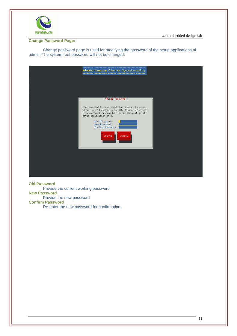
Change Password Page: Change password page is used for modifying the password of the setup applications of
admin. The system root password will not be changed.
Old Password Provide the current working password New Password Provide the new password Confirm Password
Re-enter the new password for confirmation..
..an embedded design lab
12
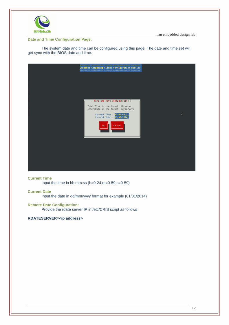
Date and Time Configuration Page:
The system date and time can be configured using this page. The date and time set will get sync with the BIOS date and time.
Current Time
Input the time in hh:mm:ss (h=0-24,m=0-59,s=0-59) Current Date
Input the date in dd/mm/yyyy format for example (01/01/2014) Remote Date Configuration:
Provide the rdate server IP in /etc/CRIS script as follows RDATESERVER=<ip address>

..an embedded design lab
13
ISCII Settings Page: This page is used for configuring the client local ISCII printing:
Printer Driver Select the appropriate printer driver for printing. Language Select the Printing Language for ISCII printing ISCII Standard Select the ISCII Standard either ISCII 83 or ISCII 88 Print Size Select print size as big or small Compress Switch On or off compression Pin 24 type Select pin 24 type
..an embedded design lab
14
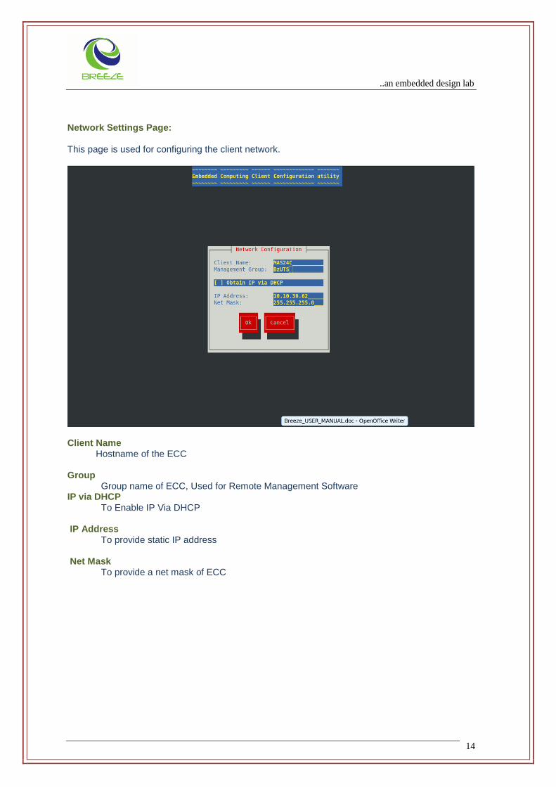
Network Settings Page: This page is used for configuring the client network.
Client Name Hostname of the ECC Group
Group name of ECC, Used for Remote Management Software IP via DHCP To Enable IP Via DHCP
IP Address To provide static IP address Net Mask
To provide a net mask of ECC

..an embedded design lab
15
DNS Configuration Page:
Domain Name Server can be configured using this page. (For example: Add new entries, Delete/Edit existing entries and copy the current entry).
Domain Name Domain Name for which the thin client needs to be configured DNS IP Address IP address of corresponding domain name.
..an embedded design lab
16
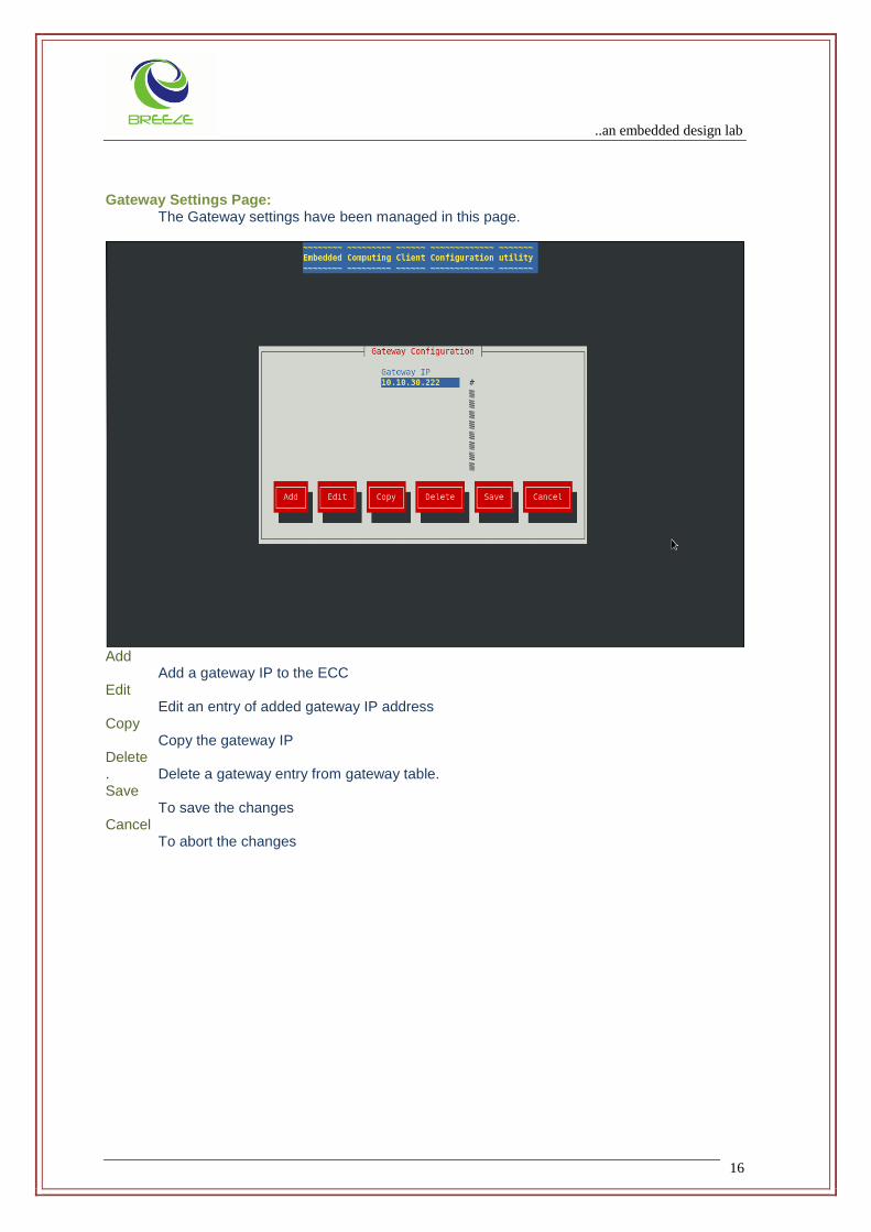
Gateway Settings Page:
The Gateway settings have been managed in this page.
Add Add a gateway IP to the ECC Edit Edit an entry of added gateway IP address Copy Copy the gateway IP Delete . Delete a gateway entry from gateway table. Save To save the changes Cancel To abort the changes

..an embedded design lab
17
Local Host Settings
Host Name Provide the hostname of host table entries Host IP Provide the host ip along with the hostname for host table.

..an embedded design lab
18
COM Port Configuration Page: The following COM port parameters can be configured using this page:
Baud Rate
Flow Control
Word width
Parity Enable/Disable
Stop Bits
Port Settings Select the COM Port (COM1 or COM2) for which the settings are to be configured.

..an embedded design lab
19
Baud Rate Speed of the COM Ports
Data Size Length of the Data Bits
Stop Bits Length of the Stop Bits Parity Parity bit settings
Flow Control Flow control of the communication
..an embedded design lab
20
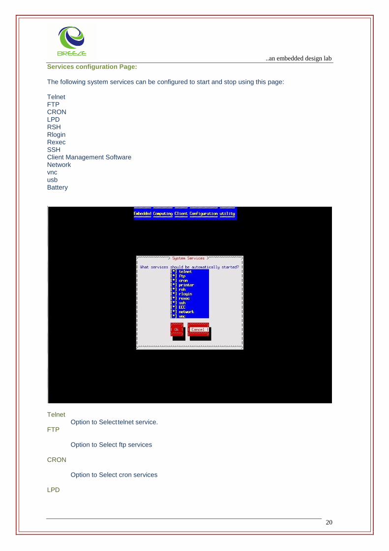
Services configuration Page: The following system services can be configured to start and stop using this page: Telnet FTP CRON LPD RSH Rlogin Rexec SSH Client Management Software Network vnc usb Battery
Telnet Option to Select telnet service. FTP Option to Select ftp services CRON Option to Select cron services LPD

..an embedded design lab
21
Option to Select lpd services RSH Option to Select remote shell services Rlogin Option to Select remote login services Rexec Option to Select rexec services SSH Option to Select Secure Shell services Client Management Software Option to Select Client Management Software services Network Option to Select network services VNC Option to Select vnc services
..an embedded design lab
22
4 USER CONFIGURATION
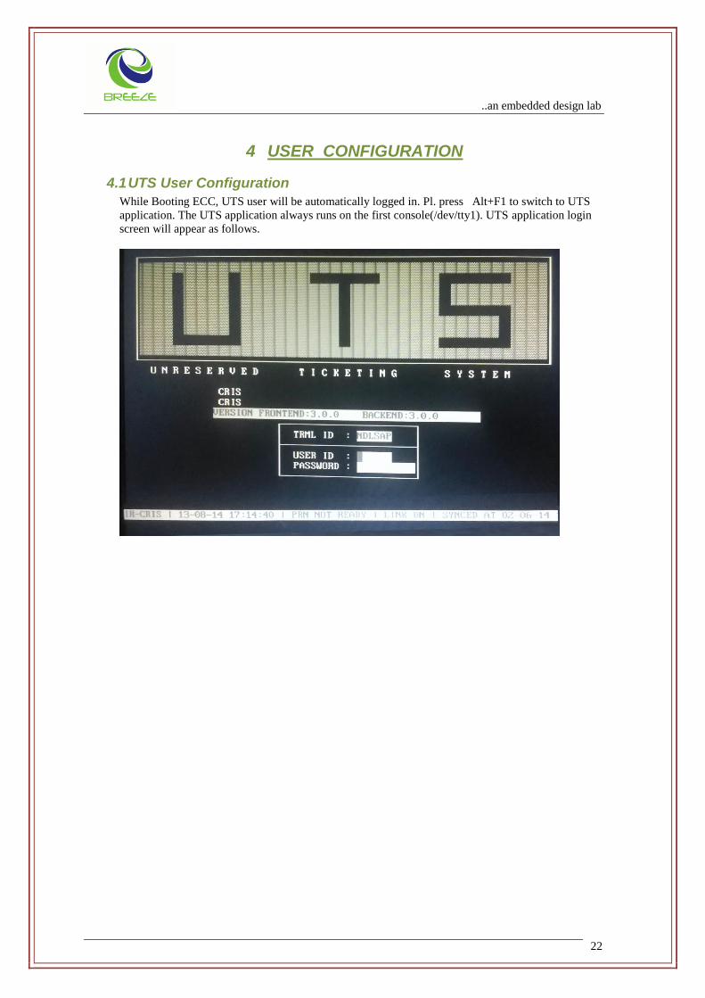
4.1 UTS User Configuration
While Booting ECC, UTS user will be automatically logged in. Pl. press Alt+F1 to switch to UTS
application. The UTS application always runs on the first console(/dev/tty1). UTS application login
screen will appear as follows.
..an embedded design lab
23
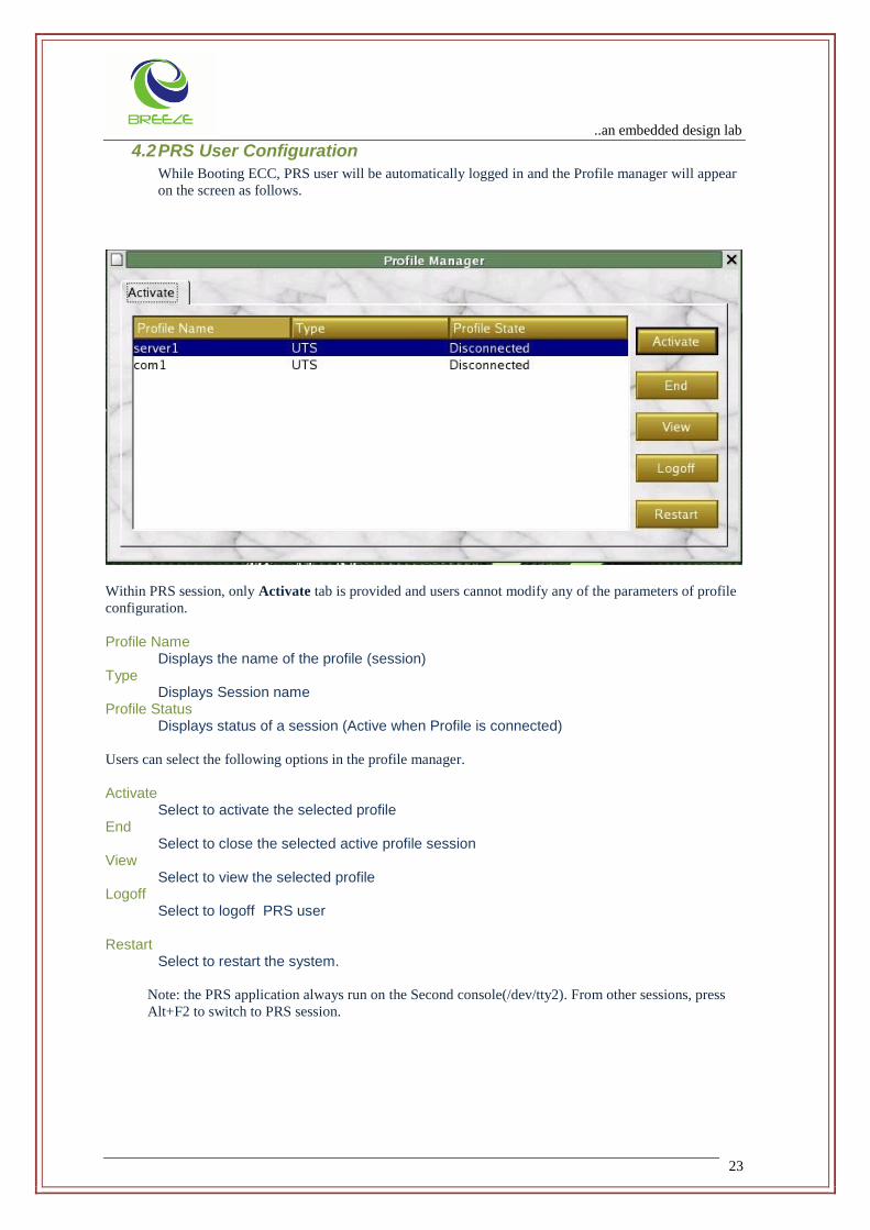
4.2 PRS User Configuration
While Booting ECC, PRS user will be automatically logged in and the Profile manager will appear
on the screen as follows.
Within PRS session, only Activate tab is provided and users cannot modify any of the parameters of profile
configuration.
Profile Name Displays the name of the profile (session) Type Displays Session name Profile Status
Displays status of a session (Active when Profile is connected)
Users can select the following options in the profile manager.
Activate Select to activate the selected profile End Select to close the selected active profile session View
Select to view the selected profile Logoff Select to logoff PRS user Restart Select to restart the system.
Note: the PRS application always run on the Second console(/dev/tty2). From other sessions, press
Alt+F2 to switch to PRS session.

..an embedded design lab
24
4.3 Vt320 User Configuration
Vt320 user has administrator privileges and this session is used to configure parameters for PRS
Application.
Within Vt320 session, Activate and Modify tabs are provided and users can modify the parameters of
profile configuration.
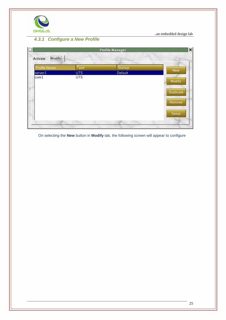
Profile Name Unique name for the session Type Connection type of the session Startup Marked with ‘default’ profile for auto start Users can select the following options in the profile manager.
New Select add a new profile or session. Max 7 sessions allowed, Modify Select to modify the configuration of the selected profile Duplicate Select to duplicate the profile Remove Select the option to remove the selected profile Setup Displaying the setup tab.
..an embedded design lab
25
4.3.1 Configure a New Profile
On selecting the New button in Modify tab, the following screen will appear to configure
..an embedded design lab
26
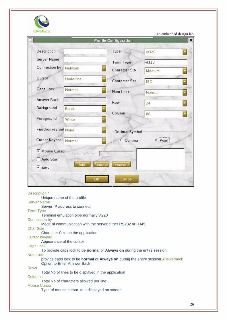
Description * Unique name of the profile Server Name Server IP address to connect Term Type Terminal emulation type normally vt220 Connection by Mode of communication with the server either RS232 or RJ45 Char Size Character Size on the application Cursor keypad
Appearance of the cursor Caps Lock To provide caps lock to be normal or Always on during the entire session. NumLock provide caps lock to be normal or Always on during the entire session.Answerback Option to Enter Answer Back Rows Total No of lines to be displayed in the application Columns Total No of characters allowed per line Mouse Cursor Type of mouse cursor to e displayed on screen
..an embedded design lab
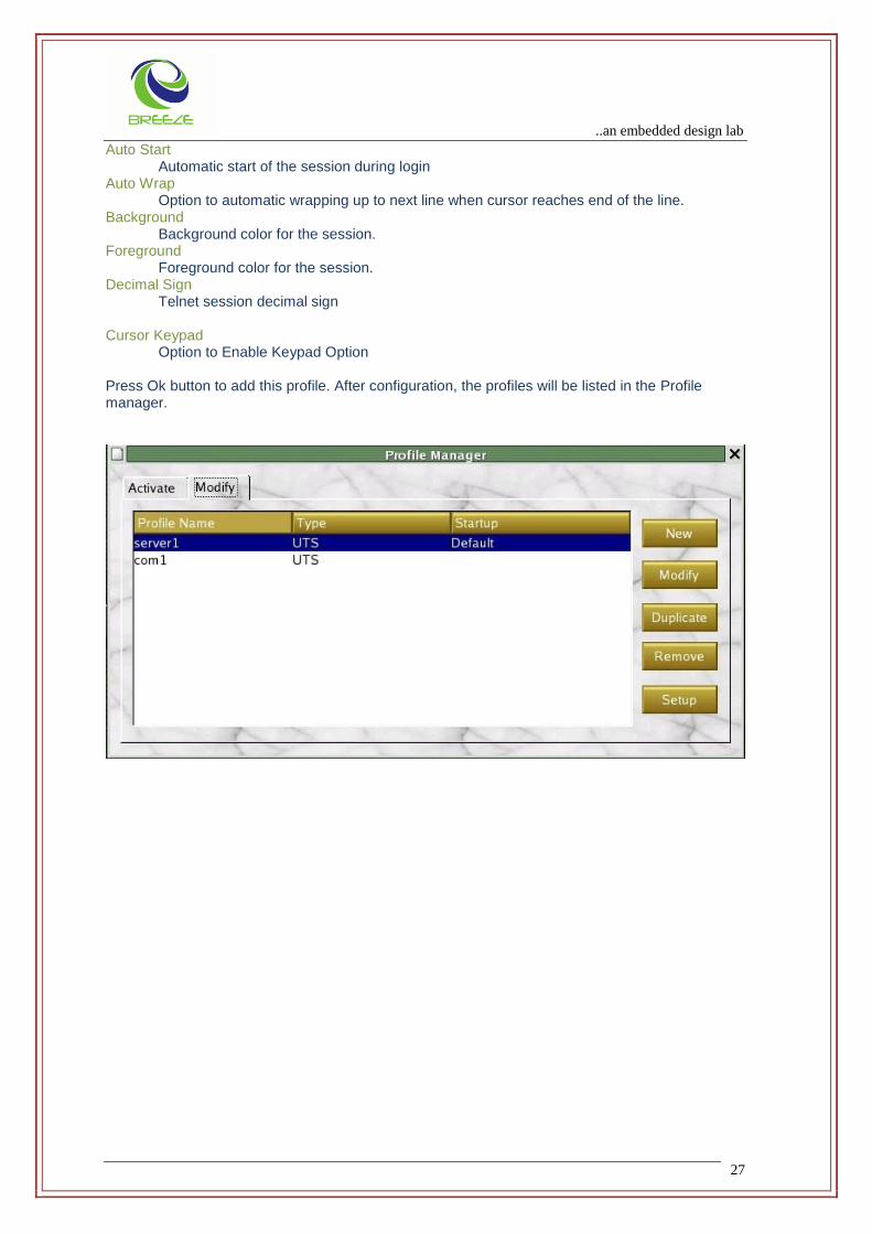
27
Auto Start Automatic start of the session during login Auto Wrap Option to automatic wrapping up to next line when cursor reaches end of the line. Background Background color for the session. Foreground Foreground color for the session. Decimal Sign Telnet session decimal sign Cursor Keypad Option to Enable Keypad Option Press Ok button to add this profile. After configuration, the profiles will be listed in the Profile manager.
..an embedded design lab
28
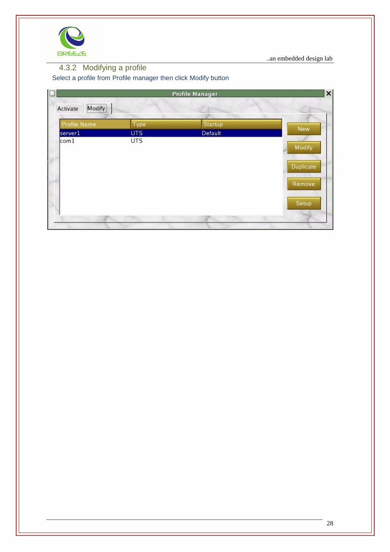
4.3.2 Modifying a profile
Select a profile from Profile manager then click Modify button

..an embedded design lab
29
Then following window will appear with the same configuration
After editing press ok to save a new configuration
..an embedded design lab
30
..an embedded design lab
31
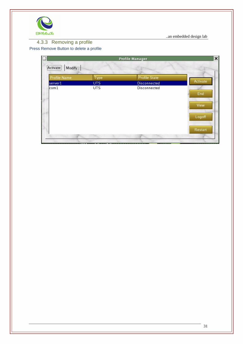
4.3.3 Removing a profile
Press Remove Button to delete a profile
..an embedded design lab
32
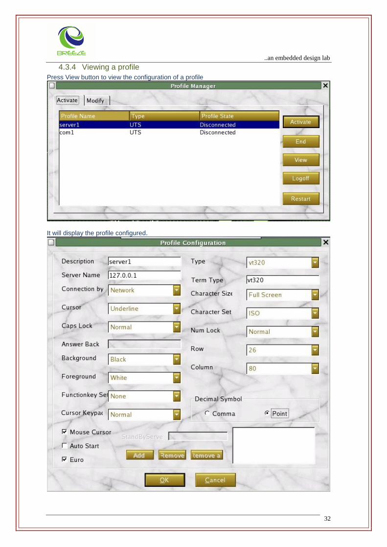
4.3.4 Viewing a profile
Press View button to view the configuration of a profile
It will display the profile configured.

..an embedded design lab
33
You are not allowed to edit any field abut you can only view configuration in this page
4.3.5 Activate a profile
Select a Profile and click Activate Button to connect a profile
The selected server gets connected.
4.4 sybuts user
This user (sybuts) is provided for Sybase database operations.
4.5 root user
root user may login in one of the consoles for administrative operations (ipconfigration, route, crond,
etc). For any parameter, that need to be saved in the ECC, pl. configure through Setup Menu. Linux
command set may not ensure persevering the terminal status for next reboot.

..an embedded design lab
34
5 LOGOFF
Select Logoff to logout from the session. The below screen appears. Select Yes or press ‘y’ to logoff or No or ‘n’ to abort.
..an embedded design lab
35
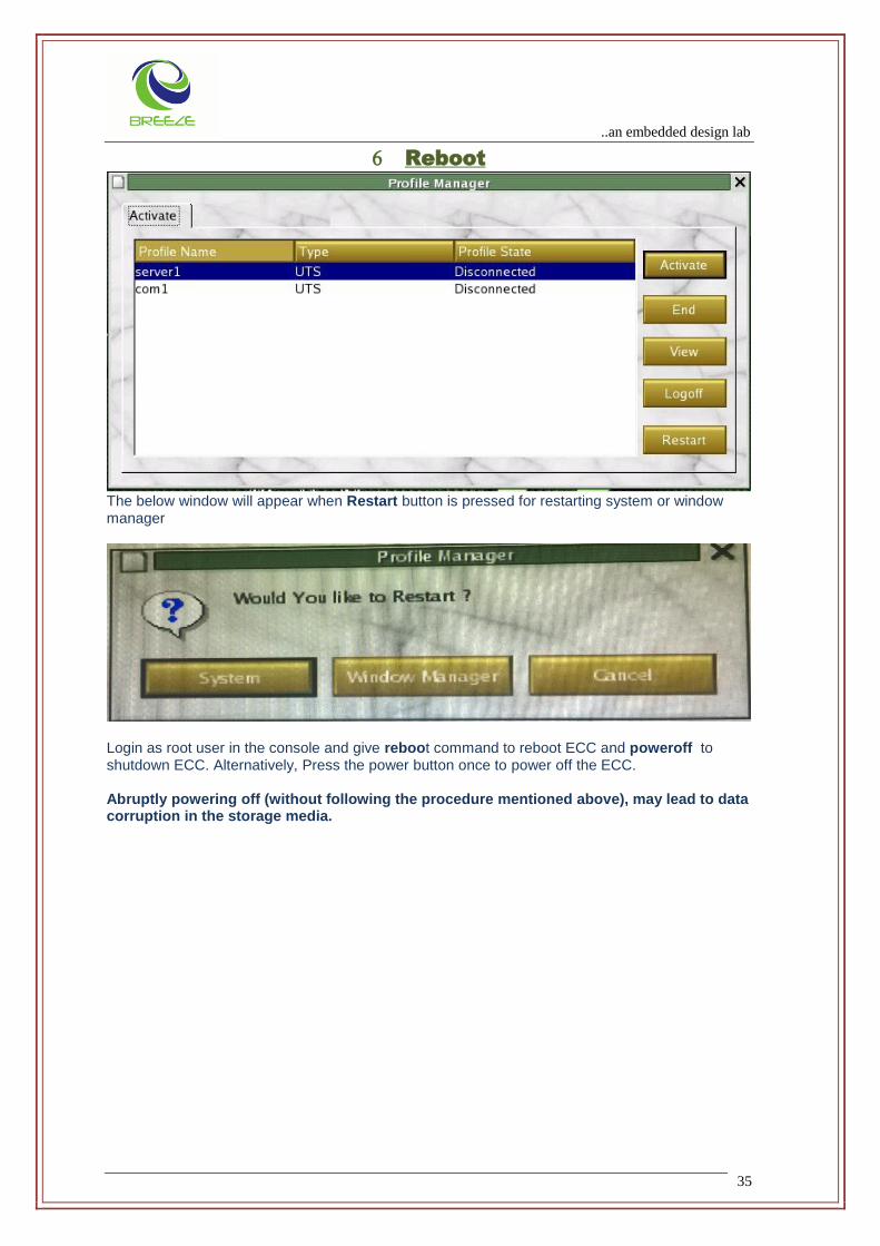
Reboot
The below window will appear when Restart button is pressed for restarting system or window manager
Login as root user in the console and give reboot command to reboot ECC and poweroff to shutdown ECC. Alternatively, Press the power button once to power off the ECC. Abruptly powering off (without following the procedure mentioned above), may lead to data corruption in the storage media.

..an embedded design lab
36
CALCULATOR
Providing the Alt+G will invoke the calculator as follows,
Options are self explanatory.
..an embedded design lab
37
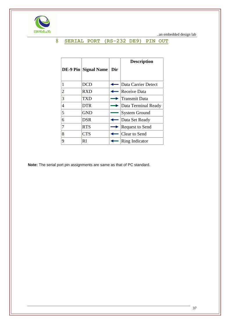
SERIAL PORT (RS-232 DE9) PIN OUT
DE-9 Pin Signal Name Dir
Description
1 DCD Data Carrier Detect
2 RXD Receive Data
3 TXD Transmit Data
4 DTR Data Terminal Ready
5 GND System Ground
6 DSR Data Set Ready
7 RTS Request to Send
8 CTS Clear to Send
9 RI Ring Indicator
Note: The serial port pin assignments are same as that of PC standard.
..an embedded design lab
38
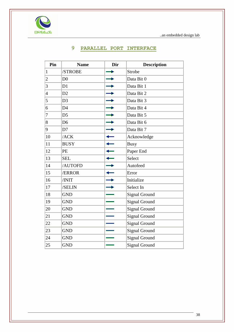
PARALLEL PORT INTERFACE
Pin Name Dir Description
1 /STROBE Strobe
2 D0 Data Bit 0
3 D1 Data Bit 1
4 D2 Data Bit 2
5 D3 Data Bit 3
6 D4 Data Bit 4
7 D5 Data Bit 5
8 D6 Data Bit 6
9 D7 Data Bit 7
10 /ACK Acknowledge
11 BUSY Busy
12 PE Paper End
13 SEL Select
14 /AUTOFD Autofeed
15 /ERROR Error
16 /INIT Initialize
17 /SELIN Select In
18 GND Signal Ground
19 GND Signal Ground
20 GND Signal Ground
21 GND Signal Ground
22 GND Signal Ground
23 GND Signal Ground
24 GND Signal Ground
25 GND Signal Ground

..an embedded design lab
39
BIOS Basic Input Output System
DOM Disk On module
RAM Random Access Memory
SO-DIMM Small Outline dual inline memory module
SDRAM Synchronized Dynamic Random Access Memory
VGA Video Graphics Adapter
UART Universal Asynchronous Reciver/Transmitter
USB Universal Serial Bus
ANSI American National Standards Institute
ASCII American Standard Code for Information Interchange
CMOS Complementary Metal-Oxide Semiconductor
COM1,COM2 The name assigned to the serial & Communication ports
CPU Central Processing Unit
CRT Cathod Ray Tube
Cursor A small Blinking rectangle or line that indicates the current position of the display screen
AC Alternating Current Electric Current that reverse its direction of flow at regular intervals
LED Light Emitting Diode
LCD Liquid Crystal Display
ROM Read Only Memory
SSH Secure Shell
RSH Remote Shell
rlogin Remote Login
Adapter A device that provides an interface between dissimilar electronic devices

..an embedded design lab
40
Boot Short form of boot strap
BPS Bits Per Second
Buffer The portion of computer memory where data is stored temporarily
Centronics The printer manufacturer whose method of data transmission between parallel printer and computer
Byte The Representation of single Charcter
DISPLAY Image Producing Device used to view computer output
MENU A software Interface that displays list of options on screen
PORT An Electrical Connection through which the computer can sends and receives to and from devices or other computer
DATA Information that is factual, measurable or statical that a computer can process store or retrieve it.
DC Direct Current the Electrical current flows in one direction
GND Ground ,An RS-232 Signal used in exchange of data between a computer and a serial device.
Bus An interface for transmission of data signal electrical power
VESA Video Electronic Standard Association
Applications A group of programs that together are used for a specific task
Binary The base two number system composed of zeros and ones (on off) used in most digital computers
Chip A small Semiconductor Devices containing computer logic circuit for processing memory input/output functions & controlling other chips also
Keyboard An input device containing switches that are activated y manually pressing marked keys.Each keystroke activates a switch that transmits the specific code to the computer