breakthroughs in low-profile leaky-wave … · leaky- wave antennas. high power microwaves (hpm)...
TRANSCRIPT

BREAKTHROUGHS IN LOW-PROFILE LEAKY-WAVE HPM ANTENNAS
Prepared by: Robert A. Koslover (PI), Greg R. Raith, and Sammuel M. Jalali
Scientific Applications & Research Associates, Inc. 6300 Gateway Drive Cypress, CA 90630-4844
21 Mar 2016 Data Item: A002 - Progress, Status, & Management Quarterly Report #10 Prepared for: Program Officer: Lee Mastroianni ONR Code 30
OFFICE OF NAVAL RESEARCH 875 North Randolph Street Suite 1425 Arlington, VA 22203-1995

i
REPORT DOCUMENTATION PAGE Form Approved OMB No. 0704-0188
Public reporting burden for this collection of information is estimated to average 1 hour per response, including the time for reviewing instructions, searching existing data sources, gathering and maintaining the data needed, and completing and reviewing this collection of information. Send comments regarding this burden estimate or any other aspect of this collection of information, including suggestions for reducing this burden to Department of Defense, Washington Headquarters Services, Directorate for Information Operations and Reports (0704-0188), 1215 Jefferson Davis Highway, Suite 1204, Arlington, VA 22202-4302. Respondents should be aware that notwithstanding any other provision of law, no person shall be subject to any penalty for failing to comply with a collection of information if it does not display a currently valid OMB control number. PLEASE DO NOT RETURN YOUR FORM TO THE ABOVE ADDRESS. 1. REPORT DATE (DD-MM-YYYY) 21-03-2016
2. REPORT TYPE Quarterly
3. DATES COVERED (From - To) 19 Dec 2015 – 20 Mar 2016
4. TITLE AND SUBTITLE Breakthroughs in Low-Profile Leaky-Wave HPM Antennas Progress, Status, & Management Report (Quarterly Report #10)
5a. CONTRACT NUMBER N00014-13-C-0352 5b. GRANT NUMBER
5c. PROGRAM ELEMENT NUMBER
6. AUTHOR(S) Koslover, Robert A.; Raith, Greg R.; Jalali, Sammuel M.
5d. PROJECT NUMBER
5e. TASK NUMBER
5f. WORK UNIT NUMBER 7. PERFORMING ORGANIZATION NAME(S) AND ADDRESS(ES)
8. PERFORMING ORGANIZATION REPORT NUMBER
Scientific Applications & Research Associates, Inc. 6300 Gateway Drive Cypress, CA 90630-4844
9. SPONSORING / MONITORING AGENCY NAME(S) AND ADDRESS(ES) 10. SPONSOR/MONITOR’S ACRONYM(S) Office of Naval Research Code 30 875 North Randolph Street Suite 1425 11. SPONSOR/MONITOR’S REPORT Arlington, VA 22203-1995 NUMBER(S) 12. DISTRIBUTION / AVAILABILITY STATEMENT Distribution Statement A. Approved for public release; distribution is unlimited. Other requests for this document shall be referred to the Program Officer listed in the contract. 13. SUPPLEMENTARY NOTES ..
14. ABSTRACT This report describes progress during the 10th quarter of this program and highlights the current status of the research. Activities this period included continuation of the investigation into improved design methods/recipes for the AAWSEA, presentation of our latest work at the DEPS 18th Annual Directed Energy Symposium, and identification of novel applications and extensions to this technology.
15. SUBJECT TERMS Leaky-wave Antennas. High Power Microwaves (HPM) Antennas. Low-profile Conformal Antennas.
16. SECURITY CLASSIFICATION OF: 17. LIMITATION OF ABSTRACT
18. NUMBER OF PAGES
19a. NAME OF RESPONSIBLE PERSON (Monitor) Lee Mastroianni
a. REPORT Unclassified
b. ABSTRACT Unclassified
c. THIS PAGE Unclassified SAR ___
19b. TELEPHONE NUMBER(incl. area code) (703) 696-3073 Standard Form 298 (Rev. 8-98)
Prescribed by ANSI Std. Z39.18

ii
Table of Contents
1. INTRODUCTION .................................................................................................................................... 1 1.1. Overview of Previous Activities (1st thru 9th Quarter) ....................................................................... 1 1.2. Overview of Recent Activities (10th Quarter) .................................................................................... 2
2. STATUS OF THE PLAN/SCHEDULE AND FUNDING ....................................................................... 3
3. RESEARCH AND ACTIVITIES PERFORMED THIS PERIOD ........................................................... 5 3.1. Status of AAWSEA design recipe development ............................................................................... 5 3.2. Beam-direction stabilization (compensation for, or suppression of, scanning) ................................. 5 3.3. Presentation at the 18th Annual Directed Energy Symposium ........................................................... 9
4. DISCUSSION, CONCLUSIONS, AND RECOMMENDATIONS ....................................................... 40

iii
List of Figures
Figure 1. Updated Program Plan ................................................................................................................... 4 Figure 2. In a forward-traveling leaky-wave antenna, the output beam direction is strongly dependent
upon frequency. .................................................................................................................................... 6 Figure 3. Generating a fixed-direction beam is possible via adding a post-leak, compensating-paths
structure. ............................................................................................................................................... 7 Figure 4. Dielectric (PE)-filling and resizing of the compensating structure reduces its size, but it is still
very large. Also, impedance-mismatch issues now more-negatively impact the resulting antenna patterns, an effect that is most visible here in the 1.2 GHz example. .................................................. 8
1
1. INTRODUCTION This is SARA’s 10h Quarterly Report for “Breakthroughs in Low-profile Leaky-Wave HPM Antennas,” a 37-month Basic Research effort sponsored by the US Office of Naval Research (ONR). This work includes fundamental theoretical analyses, numerical modeling, and related basic research. Objectives include to discover, identify, investigate, characterize, quantify, and document the performance, behavior, and design of innovative High Power Microwave (HPM, GW-class) antennas of the forward-traveling, fast-wave, leaky-wave class.
1.1. Overview of Previous Activities (1st thru 9th Quarter) During the first quarter, we prepared and established useful equations and algorithms for predicting reflections and transmission of incident TE waves from parallel-wire grills, dielectric windows, and combinations of wire grills with dielectric windows, in problems reducible to purely H-plane (2D) representations. We then applied this theory to guide the design of high-gain configurations (again, limited to 2D, H-plane representations) for linear, forward traveling-wave, leaky-wave antennas. The theory built upon equivalent circuit methods and wave matrix theory, which provided useful formalisms upon which we continue to build.
During the second quarter, we pursued initial extensions of the previous work into three dimensions, in order to include phenomena with E-plane dependencies. We succeeded in adding into the wave-matrix formalism the reflection/transmission properties associated with the transition to free space from a finite-width leaky-wave channel, including the edge-tapering essential to HPM applications. These geometric aspects do not arise in analyses confined to the H-plane alone. Our 3D analyses were somewhat more reliant on numerical models than in the 2D analyses, due to the greater complexity of identifying and/or building practical analytic approaches capable of addressing true 3D geometries of interest.
During the third quarter, we explored channel-to-channel coupling (aka, mutual coupling) which (as we have noted earlier) is an important design concern, since it can impact antenna performance significantly in terms of gain, peak power-handling, and impedance matching. Our approach leveraged mostly numerical methods, along with some intuitive arguments, as we explored designs exhibiting different degrees of mutual coupling between adjacent channels. As past and current antenna literature attest, mutual coupling analyses are non-trivial; suffice to say, there is still much work to be done in this area.
During the fourth quarter, we continued to study and employ wave-matrix based methods, but with less success than before in applying this approach to improve or optimize the initial designs. The formalism itself is still valid, but offers reduced practical rewards once an initial (i.e., not fully-optimized) geometry (e.g., grill, window, channel depth, etc.) is derived from the more basic-level principles. At that stage, we are finding that further optimization is currently best proceeding via numerical means. Additional work in the fourth quarter led us to identify new aperture geometries of potentially-significant practical value, which included the “BAWSEA” and “GAWSEA”. These configurations may significantly extend the utility of leaky-wave antenna technology to support integration on more challenging platforms.
During the fifth quarter, we designed, analyzed, and documented representative high-performance FAWSEA and CAWSEA antennas suitable for designation as “standard” or “recommended.” The configurations we described were scalable with wavelength. These are the initial entries in a library of antennas that will continue to be built throughout this program.
During the sixth quarter, we performed additional investigation of designs to support the newer curved apertures, especially the “Bent Aperture Waveguide Sidewall-emitting Antenna” (BAWSEA). We presented this work at the 17th Annual Directed Energy Professional Society (DEPS) Symposium in Anaheim, CA, on March 4th, 2015. Our full slide presentation, entitled “Advances in Low-Profile Leaky-Wave Conformable Antennas for HPM Applications,” was included in the unclassified proceedings CD that was recently distributed by DEPS to all the conference attendees.

2
During the seventh quarter, we investigated RAWSEA design considerations and showed that the angle of rotation between the leaky wave channels and the aperture can be understood in terms of an equivalent linear (non-rotated) displacement, an interpretation which helps to guide application of the wave-matrix formalism. However, more work is still needed to speed-up the RAWSEA design process.
During the eighth quarter, we identified, investigated, and applied a seemingly-simple but clarifying wave-mapping methodology, which provided improved guidance in making optimal use of generally curved platform surfaces. Following this process helps guide the designer toward a solution that provides both higher gain and greater peak power handling. Via this approach we identified and reported a notable success with the design of an improved CAWSEA that can deliver superior gain, yet still conform to the same radius cylinder as our earlier-suggested “standard/recommended” design.
During the ninth quarter, we developed/extended the ray-based analyses to the AAWSEA configuration, employing an analytic parameterization of the inner-curve (channel back-wall) and outer-curve (vicinity of the leaky-grill wall) ogives, while tracking the varying angles of reflection sequentially along the perspective leaky guide, and ultimately adjusting these curves to yield the desired output beam. The approach offered insight, but did not lead us to design recipes with a practical utility comparable to those for the FAWSEA or CAWSEA. We are continuing work in this area.
For more information, we encourage the reader to refer to our earlier Quarterly Reports #1 thru #9.
1.2. Overview of Recent Activities (10th Quarter) Recent activities included continuation of the investigation into improved design methods for the AAWSEA, presentation1 of our latest work at the DEPS 18th Annual Directed Energy Symposium, and exploration of new and novel applications/extensions to this technology. In regard to applications, we report (included in our presentation at the DEPS Symposium) the potentially advantageous use of GW-capable FAWSEA or CAWSEA-type antennas as feeds to drive larger conical dish reflectors. This combination results in increased gain (compared to the feeding antennas used in stand-alone configurations) while also providing superior peak power-handling, compared to similar-size parabolic reflectors fed by necessarily-smaller horn-type feeds. Next, combining a FAWSEA/CAWSEA feed with a conical trans-reflector and a flat twist-reflector (this configuration is now patent pending) yields, to the best our knowledge, the world’s first and only GW-class, fully-steerable, high-gain antenna. As an extension to the current leaky-wave antenna research, we are exploring ways to suppress beam-scanning with frequency. Recall that unwanted beam-scanning poses a serious limitation on the use of these antennas with broader-band HPRF sources. For these, a nearly frequency independent beam-direction is needed to maximize overall RF power on target. Although frequency-scanning behavior is fundamental to all continuous-aperture, fast traveling-wave, leaky-wave antennas, we can potentially compensate and redirect/stabilize the beam-direction by adding special structures beyond the leaky-wave interface. We provide a proof-of-principle example in this report, illustrated via a 2D model. However, the geometry in this example is not compact. Practical realization of such a compensation trick within a geometry that retains the low-profile/packaging advantages of these antennas may ultimately prove difficult to achieve, but it is definitely a worthy goal. Further information about the aforementioned new and recent activities is provided in Section 3.
1 The slides we presented at DEPS 2016 are included in this report (Section 3.3) for convenient reference.

3
2. STATUS OF THE PLAN/SCHEDULE AND FUNDING
Figure 1 (next page) maps out the updated program plan, for quick reference. The subject contract was awarded on 9/18/2013 and has an end date of 10/17/2016. The total contract value is $868,350, all of which has been authorized per P00006, dated 6/23/2015. According to SARA’s accounting system, as of March 18, 2016, expenses and commitments (including fee) totaled $706,912, thus leaving $161,438 in available funds. If one simply compares the calendar and spending on this project, we have now consumed both 81% of the calendar and 81% of the total contract value.
We thank ONR for continued support of this project. There are no new significant technical, schedule, or funding-related program problems to report at this time.

4
Figure 1. Updated Program Plan
Plan of Action and Milestones (POA&M) (updated March 2016)
Sept Q4 Q1 Q2 Q3 Q4 Q1 Q2 Q3 Q4 Q1 Q2 Q3
1.0 Program Management & Reporting 09/18/13 10/17/161.1 Kickoff Meeting (1) 1.2 Quarterly Reports (11 tot) 1.3 Annual Review Meetings (2 tot)
1.4 Final Report (1) 1.5 Final Review Meeting (1)
2.0 Prep Fundamental Analyses & Models 09/18/13 05/30/162.1 Establish/document FAWSEA theory 09/18/13 06/30/14 Continuing
2.2 Add/generalize theory to include CAWSEA 11/01/13 09/30/14 Continuing
2.3 Extend theory to include AAWSEA 04/01/14 03/31/15 Rolled into overall phase compensation analyses2.4 Add RAWSEA-specific considerations 10/01/14 05/30/16 In progress, extended --> RAWSEA theory
2.5 Extend theory to new designs (see below) 04/01/15 05/30/16 Continuing B/GAWSEA Extend theory
3.0 01/01/14 06/30/163.1 FAWSEA-based 01/01/14 09/30/14 Std design documented 12/20143.2 CAWSEA-based 04/01/14 12/30/14 Std design documented 12/20143.3 AAWSEA-based 10/01/14 06/30/16 In Progress, extnded -------------------------------> Opt. AAWSEAs3.4 RAWSEA-based 04/01/15 06/30/16 In progress Opt. RAWSEAs3.5 Designs leveraging new features (see below) 10/01/15 06/30/16 Opt new designs
4.0 07/01/14 08/01/164.1 New variant #1 (e.g., "Pinched…" → PAWSEA) 07/01/14 03/30/15 1st new design ID'd, 9/144.2 New variant #2 04/01/15 12/31/15 CAWSEA 180 2nd4.3 New variant #3 (+ any others) 01/01/16 08/01/16 Beam stabilized? 3rd +…
2015 2016Start Date
End Date
Develop & Document New Designs
~10/11/16~10/4/16
Establish Optimal/Recommended Designs
10/14, 10/15
Activity Name
11/5/2013
2013
12/13…to…6/16
2014
Design optimization & documentation
Consolidating Theory & Recipes
New variantsidentified & documented
Extended-->
Now
Continuing/updating as needed
Initiated early
BAWSEA &GAWSEAidentified
not held
Initiated earlyBAWSEA design in progress
not heldDEPS 2015
DEPS 2016

5
3. RESEARCH AND ACTIVITIES PERFORMED THIS PERIOD
3.1. Status of AAWSEA design recipe development As previously reported, we have been preparing/improving an evolving set of MatLab scripts to generate suggested/candidate values of wire size & positions and wall curvatures for a “simple” window-less 2D AAWSEA, starting with user-inputted values of the desired antenna length, curvature, center operating frequency, and desired output beam-angle relative to the initial normal. However, resulting patterns (from 2D numerical simulations) for the script-generated geometries tend to exhibit beam directions differing from that desired by ~a few degrees. In fact, the patterns and wave β in the guide are also otherwise non-optimal. At present, we attribute these problems primarily to the imperfect nature of the key approximation that a finite array of non-uniform size wires, with a wave incident in a (in this case, curved) leaky guide, can be represented satisfactorily as a locally-uniform wire array subject to an incident plane wave. Recall that we found previously that this approximation worked fairly well, not just for the straight channels of a FAWSEA or a CAWSEA (note: CAWSEA curvature minimally impacts individual channel geometries) but also for the bent channels of a BAWSEA. The AAWSEA appears to be less forgiving. Now, this does not mean that AAWSEAs cannot be designed and optimized. Rather, we are simply finding it challenging to prepare convenient recipes/scripts to generate/guide those designs.
In consideration of the remaining time and budget, if we do not make more progress on this particular theoretical path shortly, we will instead prepare one or more high-performing representative AAWSEA design examples via “brute-force” numerical methods (2D and 3D), including aperture windows, and will document these particular designs in our reports to serve as representative/useful design references.
3.2. Beam-direction stabilization (compensation for, or suppression of, scanning) The useful bandwidth associated with delivery of low-VSWR, high-gain, and high peak-power capabi-lities in a FAWSEA (or similar antenna in this family) can easily exceed +/- 10%. But if one adds a requirement that the beam not appreciably change direction as a function of frequency, usable bandwidth is substantially reduced. Now, this is not usually a serious limitation when employing a source with a narrow instantaneous bandwidth (i.e., a frequency relatively-stable throughout a single-pulse or during a rapid-train of output pulses). Indeed, even if such a source is tunable (e.g., by +/-10%), the antenna beam simply points in a slightly new (and generally quite-usable) direction once the source is tuned to its new frequency. Rather, the problem we speak of here is if the source output spectra spans significant bandwidth (e.g., +/- 10%) during a single pulse or a rapid-train of output pulses. Under such conditions, there is no unique direction to the output beam, yielding a situation2 where only a frequency-subset of the radiated power can be oriented toward an intended target.
Consider now a simple 2D FE model of a 2m-long, window-less leaky-wave antenna (L-band example), shown in Figure 2. Note how the beam direction changes with frequency. In Figure 3, we’ve added a set of parallel conducting walls to the same model, outside the leaky grill, to constrain direction of the leaked waves and simultaneously enforce local propagation with the same dispersion relationship as in the leaky guide (with plate spacing set the same as the effective-height of the leaky guide). This yields nearly-constant electrical-paths for all signals reaching the final aperture, regardless of frequency. Thus, the output beam direction becomes fixed. Figure 4 shows a similar arrangement using dielectric (PE) filled channels to shrink the geometry a bit. Some impedance mismatching occurs, but the method still works. We will continue to seek more compact arrangements, perhaps including folding of paths (in 3D) arguably somewhat analogous to the (albeit, shorter-length) curved guide sections in a RAWSEA.
2 This is not to be confused with issues arising due to finite antenna fill-time. We are limiting the consideration here to waveforms with pulse-lengths sufficiently long, and frequency variation sufficiently gradual, that effects due to antenna fill-time can be ignored.

6
Figure 2. In a forward-traveling leaky-wave antenna, the output beam direction is strongly dependent upon frequency.

7
Figure 3. Generating a fixed-direction beam is possible via adding a post-leak, compensating-paths structure.

8
Figure 4. Dielectric (PE)-filling of the compensating structure reduces its required size, but it is still very large. Also, impedance-mismatch issues now more-negatively impact the resulting antenna patterns, an effect that is most visible here in the 1.2 GHz example.

9
3.3. Presentation at the 18th Annual Directed Energy Symposium The Directed Energy Professional Society (DEPS)18th Annual Directed Energy Symposium was held in Albuquerque, NM, March 7-11, 2016. SARA’s PI, Dr. Robert Koslover, presented an update on our research at the Tuesday-morning session on “HPEM Systems and Technologies.” Our presentation title was “Improvements in Low-Profile HPM-Capable Conformable Leaky-Wave Antennas.”
We are pleased to report that the number of people attending our presentation was substantial, over-flowing the meeting-room’s capacity. Perhaps most notable among those who asked questions or offered comments was Prof. John L. Volakis3 of Ohio State University, who expressed interest in including some of our work in the next edition of the Antenna Engineering Handbook4, which he edits (currently in its 4th edition). Of course, we welcome such high-profile attention to this research. We have provided Prof. Volakis with copies of the slides from our 2015 & 2016 presentations at DEPS about our research in HPM leaky-wave antennas, and will follow up with him in the future, as appropriate.
For completeness, the slides from our DEPS 2016 presentation are included on the pages that follow.
3 See http://esl.eng.ohio-state.edu/~volakis/ 4 http://www.amazon.com/Antenna-Engineering-Handbook-Fourth-Edition/dp/0071475745

10
3/8/2016
Improvements in Low-Profile HPM-Capable Conformable Leaky-Wave Antennas
Eighteenth Annual Directed Energy SymposiumMarch 7-11, 2016
Dr. Robert Koslover (PI)Mr. Greg Raith
Dr. Sammuel Jalali
Scientific Applications & Research Associates (SARA), Inc.www.sara.com
Work supported by: • Office of Naval Research (ONR), Contract # N00014-13-C-0352.• SARA, Inc. IR&D
1Distribution Statement A. Approved for public release; distribution is unlimited.

11
3/8/2016 2
Abstract
We report the latest results of SARA’s continuing research in the design and optimization of low-profile, sidewall-emitting, forward traveling-wave, leaky-wave HPM-capable antennas. Subject to surprisingly-few hard constraints, leaky-wave apertures supporting up to multi-GW peak powers are realizable in flat, simply-curved, multiply-curved, and even disconnected/irregularly-shaped forms, thus offering many appealing options for fitting and integrating these antennas into compact HPM-based DEW platforms. Our approach to designing these antennas continues to leverage application of continuous-aperture leaky-wave theory in concert with iterative 2D and 3D full-wave numerical EM models, with which we are growing a catalog of representative antenna configurations that deliver high gain, low VSWR, respectable bandwidth, and other desirable features. Both recent and earlier designs that offer especially-desirable performance characteristics while conforming to geometries of interest are highlighted and discussed.
We gratefully acknowledge the support for this work provided by the Office of Naval Research (ONR) via Contract # N00014-13-C-0352.
Distribution Statement A. Approved for public release; distribution is unlimited.

12
3/8/2016 Distribution Statement A. Approved for public release; distribution is unlimited. 3
Outline
• Background: Sidewall-emitting, forward traveling-wave, leaky-wave antennas
• Why use these types of antennas for HPM?• Operating principles• Enabling GW-class operation• Curved-aperture types/naming
• Example Designs & Performance• Optimizing field-distributions for curved apertures
• An improved CAWSEA
• Extra: How to build a Ppk> 1 GW, fully-steerable, high-gain antenna

13
3/8/2016 4
Support for extremely high (up to multi-GW) peak power High gain and aperture efficiency Low-profile (thickness < λ0) Bandwidth sufficient for most HPM sources Aperture(s) conformable to flat and curved surfaces Customizable aperture sizes and aspect ratios Potential for beam-steering Rugged and compatible with realistic environments No exotic materials required
Why use sidewall-emitting, forward traveling-wave, leaky-wave antennas in HPM?
continuedDistribution Statement A. Approved for public release; distribution is unlimited.

14
3/8/2016 5Distribution Statement A. Approved for public release; distribution is unlimited.
Successful HPM tests at AFRL/RDH (2007-8).
Curved Aperture Waveguide Sidewall-Emitting Antenna (CAWSEA) 2009
Arched Aperture Wave-guide Sidewall-Emitting Antenna (AAWSEA) 2010
Only 4.7” (at fo = 1.27 GHz)
Rotated Aperture Waveguide Sidewall-Emitting Antenna (RAWSEA) 2012
Aperture
4
1 2 3Flat Aperture Waveguide Sidewall-Emitting Antenna (FAWSEA) – invented 2004
End view:
SARA has investigated novel designs & geometries for these antennas over the years, including (for example):
Bent Aperture Waveguide Sidewall-Emitting Antenna (BAWSEA) 2014
5

15
3/8/2016 6
Generalization to fit almost arbitrary surfaces
ObstaclesGAWSEA
Aperture customized to fit the platform’s surface and curvature while avoiding obstacles and phased to match a radiated plane wave. (Notional Example)
Obstacles
Generalized Aperture Waveguide Sidewall-Emitting Antenna (GAWSEA) combines curvatures typical of CAWSEA, AAWSEA, and/or BAWSEA, to fit a distributed aperture to a platform and deliver maximum power density to the target.
Apertures 1a & 1b linked by hidden/interior channels
Distribution Statement A. Approved for public release; distribution is unlimited.

16
3/8/2016 7
Basics: Traveling wave leaks through leaky-waveguide sidewall
• TE10 mode Interpret as two plane waves reflecting from the walls at an angle θ. • Replace one sidewall with a partially-transmitting wire grill (wires parallel to E) • Let Tpow = 1-Rpow = power fraction leaking through per reflection.
h …etc.E
s
θ
Solid wall
Leaky wall
The power in the guide remaining at the distance z+∆z is given by:
z z+∆zP=P(z) P=P(z+∆z)
szpowzzz RPP ∆
∆+ =
since ∆z/s = the number of bounces between z and z+∆z. In the limit as ∆z0, this becomes:
For TE10: s = 4h2/λg, λg = λ0/sinθ, and cosθ = fc/f, where fc is the cutoff frequency: fc=c/2h.
( ) ( )zdzdP
zPα−=
1with ( ) ( )pow
g Rh
z ln4 2
λα −=
continued
0PpowRP0
20 powRP
powRP0
∆z
WAVEGUIDE
Distribution Statement A. Approved for public release; distribution is unlimited.
(Simplifiedanalyses)

17
3/8/2016 8
Understanding uniform leaky grills via equivalent circuits
• Transmission & reflection of TE & TM-incident planewaves at infinite, uniform, arrays of grill wires are discussed in the Waveguide Handbook (N. Marcuvitz, 1951.)
• Marcuvitz employed an approximate equivalent-circuit transmission-line (TL) model*. (Others have added various correction terms and expanded on it.)
• R.C. Honey (1959) used these methods with much success with his “Flush-Mounted Leaky-Wave Antenna.”
• ~Earliest work on this subject: H. Lamb, “On the Reflection and Transmission of Electric Waves by a Metallic Grating,” Proc. London Math. Soc., v. 29, pp. 523-544; 1898.
• Research on leaky-wave antennas leveraging “Partially Reflecting Surfaces” (PRS) continues to the present day.
(Borrowed from N. Marcuvitz, Waveguide Handbook)*More recent papers call this circuit-centric approach the “Transverse Equivalent Network” (TEN) method.
Distribution Statement A. Approved for public release; distribution is unlimited.

18
3/8/2016 9
Consider an aperture of length L. To maximize gain & peak-power handling, impose: (1) All the power to radiate from the guide in length L; and (2) Uniform leakage (to yield uniform |E| on aperture)
LP
dzdP 0−= ( )
−=
LzPzP 10 ( ) ( )z
dzdP
zPα−=
1But, from before,
Solving for α: ( )zL
zideal −=
1α ( ) ( )powg R
hz ln
4 2
λα −=But recall:
Combining these, yields: ( )
−−=
zLhR
gidealpow λ
2
,4exp
In summary, we now have:1. Rpow as a function of wire diam, spacing, angle of incidence, and frequency.2. The desired Rpow (aka, Rpow, ideal) for optimal gain & Ppk handling in a leaky guide.
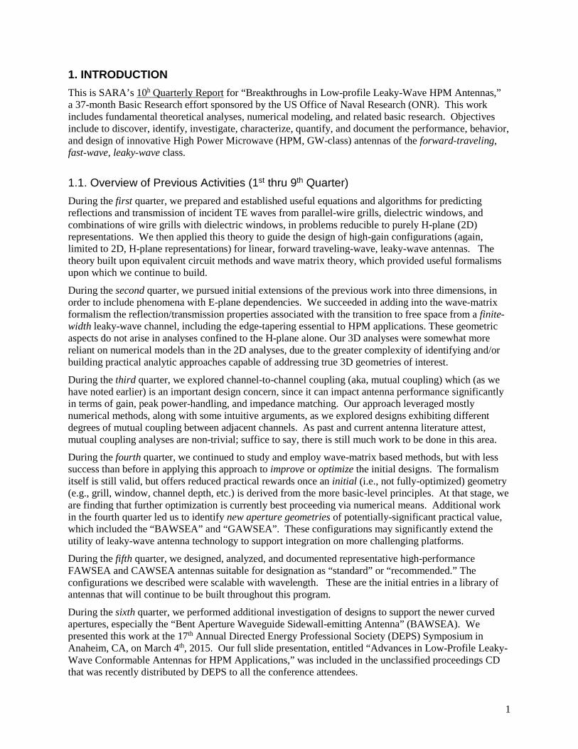
Set Rpow (θ,a,d,f,z) = Rpow,ideal (L,h,z), solve for the undetermined variables to yield a starting-set (wire sizes, spacing) for the leaky grill, then optimize further*.
continued
Extension to non-uniform wire grills.
Distribution Statement A. Approved for public release; distribution is unlimited.
*Additional and more detailed theoretical treatment including accounting for interfaces, aperture-curvature, etc. is provided in the periodic technical reports delivered under ONR Contract # N00014-13-C-0352.
19
3/8/2016 Distribution Statement A. Approved for public release; distribution is unlimited. 10
Example: 2D finite-element model using a wire-grill generated via the aforementioned approach.
Predicted H-plane pattern (normalized to 0dB)
Leaky interface composed of various-diameter wires (159 wires)
Example
Narrow output beam pointsin the intended direction.
20
3/8/2016 Distribution Statement A. Approved for public release; distribution is unlimited. 11
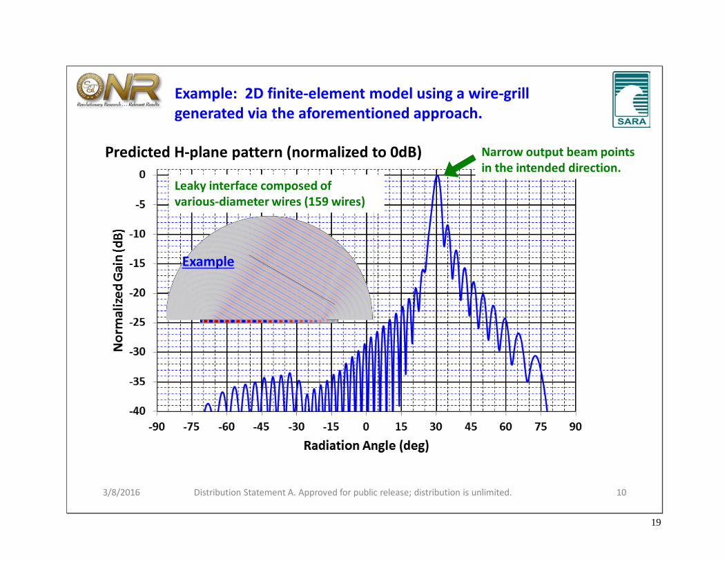
The analyses we used to define the FAWSEA grill wires can be extended* to guide the design of arched (AAWSEA) configurations.
Example 2D design50-wire leaky-grill (f=1.015 GHz)
From
: R
K_m
od_A
AW
S_2D
_N1n
s.mph
Desired conformal geometry.Grill designed for uniform power out.
Opposite wall. Curvature chosen to preserve the fixed-angle output beam
Input
*See the periodic technical reports delivered under ONR Contract # N00014-13-C-0352.

21
3/8/2016 12
Adapted from: Honey, R.C., “A Flush-Mounted Leaky-Wave Antenna with Predictable Patterns,” IRE Trans. Antennas and Propagat., 7, pp. 320-329, 1959.
Classic designs from the literature are not immediately-suitable for HPM:
continued
E
Dipole-like feed unsuitable for HPM
Field enhancements at aperture edges could initiate flashover
Geometry does not reject higher-order modes, if feed is replaced by a waveguide
Low profile
Wide range of areas and aspect ratios
Sufficient bandwidth
From: Ishimaru, A., and F. R. Beich, “Pattern Synthesis With a Flush-Mounted Leaky Wave Antenna on a Conducting Circular Cylinder,” J. Research of The Nat. Bureau Of Standards-D. Radio Propagat. 66, No.6, pp. 783-796, Nov-Dec, 1962.
Conforms to a curved aperture
Direct waveguide-feed
EField enhancements at aperture edges could initiate flashover
Flat aperture Aperture curved in H-plane
…but the concepts they embody are extendable to GW-class HPM antennas.
Distribution Statement A. Approved for public release; distribution is unlimited.
Enabling HPM operation

22
3/8/2016 13
Enabling HPM operation, cont.
*I.e., 79% of the gain arising from a perfectly-uniform amplitude and phase across the aperture.
Ppk goal for this 1st HPM prototype was 400 MW.
Originalcross-section
~79% aperture efficiency*
Numerically-predicted aperture efficiency vs. frequency.
Improved design
Tested up to 542 MW (at AFRL/RDH)No arcs or breakdown.
HPM Enablers• Evacuated waveguides
support intense E fields• Aperture edges ⊥ to E
are external to the leaky grill, rounded, and under vacuum
• Leaky wire grill is parallel to E, so no field enhancements there.
• Division into multiple channels suppresses higher-order modes.
• E at triple points is strongly suppressed by recessed tracks and symmetry.
Improved cross-section(reduces cross-coupling)
Distribution Statement A. Approved for public release; distribution is unlimited.

23
3/8/2016 14
Curved Aperture Types/NamingSARA’s growing family of low-profile, forward-traveling, fast-wave, leaky-wave HPM antennas now includes:
Distribution Statement A. Approved for public release; distribution is unlimited.
20162004

24
3/8/2016 Distribution Statement A. Approved for public release; distribution is unlimited. 15
Outline
• Background: Sidewall-emitting, forward traveling-wave, leaky-wave antennas
• Why use these types of antennas for HPM?• Operating principles• Enabling GW-class operation• Curved-aperture types/naming
• Example Designs & Performance• Optimizing field-distributions for curved apertures
• An improved CAWSEA
• Extra: How to build a Ppk> 1 GW, fully-steerable, high-gain antenna

25
3/8/2016 16
Some examples* of practical 4-channel designs
continuedDistribution Statement A. Approved for public release; distribution is unlimited.
FAWSEA
CAWSEA (90o example)
BAWSEA (60o example)RAWSEA
Dimensions shown are for f0 = 1.0 GHz. (For other center frequencies, scale with λ0)
21 cm
15 cm
*For detailed design/geometry information, please refer to the periodic technical reports delivered to date under ONR Contract # N00014-13-C-0352.

26
0%
25%
50%
75%
100%
0.90 0.95 1.00 1.05 1.10
Ap. E
ffic
ienc
y
Frequency (f/f0)
Theoretical ideal leaky-wave
4ch FAWSEA
4ch BAWSEA
4ch CAWSEA
18.0
19.0
20.0
21.0
22.0
23.0
24.0
0.90 0.95 1.00 1.05 1.10
Gai
n (d
B)
Frequency (f/f0)
q y
4ch FAWSEA
4ch BAWSEA
4ch CAWSEA
3/8/2016 Distribution Statement A. Approved for public release; distribution is unlimited. 17
Comparing FAWSEA, BAWSEA, & CAWSEA with ~same aperture areas.
1.00
1.05
1.10
1.15
1.20
1.25
1.30
0.90 0.95 1.00 1.05 1.10
VSW
R
Frequency (f/f0)
Predicted VSWR (effective) vs frequency
One Straight Chan
4ch FAWSEA
4ch BAWSEA
4ch CAWSEA
10.0
15.0
20.0
25.0
0.90 0.95 1.00 1.05 1.10
Max
E (k
V/cm
)
Frequency (GHz)
Highest Emax vs frequency on exposed exterior window surface if total Pin = 1 GW
4ch FAWSEA4ch BAWSEA4ch CAWSEA
10.0
20.0
30.0
40.0
0.90 0.95 1.00 1.05 1.10
Beam
Tilt
(deg
)
Frequency (f/f0)
Theoretical
Model
Predicted Beam Tilt (FAWSEA) rel. to normal vs frequency
Predicted Gain vs frequency
Predicted Aperture Efficiency vs frequency

27
18
4-chan CAWSEA(G=21.0 dB at f=f0)
4-chan FAWSEA (G=22.8 dB at f=f0)
E-plane cut at 30o
E-plane cut at 30o
Examples of practical designs, cont.
3/8/2016 Distribution Statement A. Approved for public release; distribution is unlimited.
Computed 3D patterns and principal-plane cuts at f=f0
E-plane* cut at 30o
4-chan BAWSEA (G=21.9 dB at f=f0)
FAWSEA CAWSEA BAWSEA

28
3/8/2016 Distribution Statement A. Approved for public release; distribution is unlimited. 19
Outline
• Background: Sidewall-emitting, forward traveling-wave, leaky-wave antennas
• Why use these types of antennas for HPM?• Operating principles• Enabling GW-class operation• Curved-aperture types/naming
• Example Designs & Performance• Optimizing field-distributions for curved apertures
• An improved CAWSEA
• Extra: How to build a Ppk> 1 GW, fully-steerable, high-gain antenna

29
3/8/2016 20
Optimizing field-distributions for curved aperturesQ: What’s the best way to distribute E across a curved-surface, to radiate a high-gain beam?
A: There is more than one way to “back-project” a to-be-radiated plane-wave (Epl) to “match” a surface-tangential aperture (Eap). The three methods below all yield Eapdistributions matching the phase of a plane wave:
Distribution Statement A. Approved for public release; distribution is unlimited.
Type of Projection
Why consider it?
Equation (yields purely surface-tangential Eap) Effect upon Impact on surface
breakdown risk
Direct Simple & reasonable
strongest where the surface is best directed to generate the desired beam.
LOW RISK
Magnitude-preserving
Best for peak-power handling is uniform. LOWEST
POSSIBLE RISK
Magnitude-enhancing
Speculation about achieving higher gain
strongest where the surface is most-poorly oriented to generate the desired beam, to attempt to compensate.
Large |Eap| in some places INCREASED RISK.

30
3/8/2016 Distribution Statement A. Approved for public release; distribution is unlimited. 21
Optimizing field-distributions for curved apertures, cont.
12.013.014.015.016.017.018.019.020.021.022.023.0
0.5 0.6 0.7 0.8 0.9 1 1.1 1.2 1.3 1.4 1.5
Dire
ctiv
ity (d
B)
Frequency (GHz)
Cylinder, 25cm radius, 1m long, axis 60o rel to k0
Magnitude preserving projection
Direct projection
9.010.011.012.013.014.015.016.017.018.019.0
0.5 0.6 0.7 0.8 0.9 1 1.1 1.2 1.3 1.4 1.5
Dire
ctiv
ity (d
B)
Frequency (GHz)
Hemisphere, 25cm radius
Magnitude preserving projection
Direct projection
13.014.015.016.017.018.019.020.021.022.023.024.0
0.5 0.6 0.7 0.8 0.9 1 1.1 1.2 1.3 1.4 1.5
Dire
ctiv
ity (d
B)
Frequency (GHz)
Cylinder with Ogive, 25cm radius. Cyl: 75 cm long, Ogive: 75 cm long. Axis 60o rel to k0
Magnitude preserving projection
Direct projection
Direct Mag preserving
Direct Mag preserving
Direct Mag preserving
The “Magnitude Preserving” projection yields greater directivity, in all three examples.
We used numerical models to explore directivity achievable with idealized surfaces:
Mag preserving
Direct
Mag preserving
Mag preserving
Direct
Direct
Cylinder
Hemisphere
Cylinder & Ogive
Desi
red
beam
Dire
ctiv
ity (d
B)D
irect
ivity
(dB)
Dire
ctiv
ity (d
B)

31
3/8/2016 Distribution Statement A. Approved for public release; distribution is unlimited. 22
The preceding curved-aperture analyses suggested the possibility of:
An improved CAWSEA (to fit a fixed-radius cylinder)16-chan CAWSEA180 (new!)4-chan CAWSEA90
(presented at DEPS in 2015)
Cross-section of4-chan CAWSEA90
(from our earlier “recommended” design)
Cross-section of16-chan CAWSEA180
to fit in the same radius cylinder
Half-antennas, with symmetry, are used in the
numerical models
2 different feed lengths compensate for phase error
Employs 8 different feed lengths ∆Ln to compensate for phase error.
Shorter here due to computed phase correction > 360o, so we can subtract one guide wavelength.
From: Rev2_ThinChan_CAWSEA_180_comp_phased.mphFrom: FourChan_Std_CAWSEA_5e_Optfor1GHz_phdelayed.mph
θφ sincos0n
gn R
kkL =∆
φn= nth azim angle from ctrθ = tilt of axis rel to zk0 = free wavenumber at f0kg = guide wavenumber at f0.R = cyl radius to aperture
Subtends 2x azimuthal angle, using channels half as wide as the 4-chan CAWSEA.
continued
vs.
{Note: We need 16 instead of 8 channels to make this work, to support the larger gradients in phase required at large azimuthal angles.}

32
3/8/2016 Distribution Statement A. Approved for public release; distribution is unlimited. 23
An Improved CAWSEA, cont.
16-chan CAWSEA1804-chan CAWSEA90
Computed 3D gain patterns at f0=1.0 GHz. Phase-compensated CAWSEAs(RF model outline included to clarify antenna orientation.)
From: Rev2_ThinChan_CAWSEA_180_comp_phased.mphFrom: FourChan_Std_CAWSEA_5e_Optfor1GHz_phdelayed.mph
G = 21.03 dBG = 23.66 dB
That’s +2.63 dB more gain. And the new antenna fits into the same diameter cylinder.
continued

33
3/8/2016 Distribution Statement A. Approved for public release; distribution is unlimited. 24
An Improved CAWSEA, cont.
From: ThinChan_CAWSEA_180_notes.xlsx
+2.63 dB increase!

34
3/8/2016 Distribution Statement A. Approved for public release; distribution is unlimited. 25
Outline
• Background: Sidewall-emitting, forward traveling-wave, leaky-wave antennas
• Why use these types of antennas for HPM?• Operating principles• Enabling GW-class operation• Curved-aperture types/naming
• Example Designs & Performance• Optimizing field-distributions for curved apertures
• An improved CAWSEA
• Extra: How to build a Ppk> 1 GW, fully-steerable, high-gain antenna

35
3/8/2016 Distribution Statement A. Approved for public release; distribution is unlimited. 26
Extra: How to build a Ppk> 1 GW, fully-steerable, high-gain antenna
Background: Over a decade ago, SARA developed “The world’s first truly-steerable HPM antenna”
continued
• G~29dB (L-band).• Very widely-steerable in
azimuth and elevation.
Risk of air/surface breakdown at the feed constrained operation to about 100-200 MW peak.
Pyramidal horn feed
Steerabletwist-reflector
Parabolictrans-reflector
H-polV-pol
H-to V-pol rotation
occurs here
V-pol
US Patent No. 6,559,807, May 6, 2003.Work supported by US Army/ARL Contract # DAAD17-01-C-0071.
So… what if you want to operate at Ppk > 1 GW?

36
Conical trans-reflector
Leaky-wave feed
Flat twist-reflector
3/8/2016 Distribution Statement A. Approved for public release; distribution is unlimited. 27
Extra: How to build a Ppk> 1 GW, fully-steerable, high-gain antenna, cont.
1. Replace the pyramidal horn feed with a suitable GW-class FAWSEA or CAWSEA.2. Replace the offset parabolic trans-reflector with suitable offset conical trans-reflector.
Developed under SARA IR&D. U.S. Patent Pending.Application No. 14/678,835 (filed 4/3/15). continued

37
3/8/2016 Distribution Statement A. Approved for public release; distribution is unlimited. 28
Extra: How to build a Ppk> 1 GW, fully-steerable, high-gain antenna, cont.
Ex Ey
From
: Tra
nsre
f_tw
istre
f_1.
mph
Conical trans-reflector
Flat twist-reflector(2-axis tiltable)
Leaky-wave feed (GW-class)
Radiated output(steerable)
Result A fully-steerable, GW-class, high-gain antenna!
continued
3D model showing H-pol component Same model, showing V-pol component
Developed under SARA IR&D. U.S. Patent Pending.Application No. 14/678,835 (filed 4/3/15).

38
3/8/2016 Distribution Statement A. Approved for public release; distribution is unlimited. 29
Steered 3D patternThe “pencil beam” is well-preserved.
Example: Steering the beam by 30o in azimuth (via rotating the twist-reflector 15o) reduces the predicted gain by only 0.18 dB relative to the un-steered case.
Ey
3D numerical model
Extra: How to build a Ppk> 1 GW, fully-steerable, high-gain antenna, cont.
Developed under SARA IR&D. U.S. Patent Pending.Application No. 14/678,835 (filed 4/3/15).

39
3/8/2016 Distribution Statement A. Approved for public release; distribution is unlimited. 30
For more information…
At SARA
Dr. Robert KosloverPrincipal InvestigatorPh: (903)[email protected]
Mr. Sean AhernBusiness DevelopmentPh: (714)[email protected]
At ONR
Joong Kim, PhDProgram Officer, Code 30Office of Naval ResearchPh: [email protected]
Mr. Lee MastroianniExpeditionary Maneuver Warfare and Combating Terrorism S&T (Code 30)Ph: (703) [email protected]
At AFRL/RDH
Dr. Andrew GreenwoodSenior Electronics Engineer AFRL/RDHEPh: (505)[email protected]

40
4. DISCUSSION, CONCLUSIONS, AND RECOMMENDATIONS
Work performed during this 10th quarter of the R&D program included continuation of our investigation into improved design methods/recipes for the AAWSEA, presentation of our work at the DEPS 18th Annual Directed Energy Symposium, and identification of novel applications and extensions to this technology.
In the coming quarter, we plan to advance and further document the design recipes and our “standard/ recommended” designs for each of the multiple-identified variants of forward-traveling, fast-wave, leaky-wave HPM-capable antennas.
As always, we appreciate ONR’s continuing support for this R&D.

41
BIBLIOGRAPHY (alphabetical) Bodnar, D.G. and D.T. Paris, “New Variational Principle in Electromagnetics,” IEEE Trans. Antennas & Propagat, vol. AP-18, pp. 216-223, 1970 Goldstone, L.O. and Oliner, A.A., “Leaky-Wave Antennas I: Rectangular Waveguides," IRE Trans. Ant. and Propagat., Oct., 1959, pp. 307-319. Goldstone, L.O. and Oliner, A.A., “Leaky-Wave Antennas II: Circular Waveguides," IRE Trans. Ant. and Propagat., May., 1961, pp. 280-290. Honey, R.C., “A Flush-Mounted Leaky-Wave Antenna with Predictable Patterns,” IRE Trans. Antennas and Propagat., 7, pp. 320-329, 1959. Ishimaru, A.K. and Beich, F.R., “Pattern Synthesis With a Flush-Mounted Leaky Wave Antenna on a Conducting Circular Cylinder,” J. of Res. of the Nat. Bureau of Standards-D. Radio Propagat Vol. 66D, No.6, Nov- Dec. 1962, pp. 783-796. Jull, E.V., “Radiation from Apertures,” Chap. 5 of Antenna Handbook: Theory, Applications, and Design, Ed. by Y.T. Lo and S.W. Lee, Van Nostrand Reinhold, NY, 1988. Lewin, L., “Theoretical analysis of the junction discontinuity between a straight and a curved section of rectangular waveguide,” Proc. IEE, Vol. 124, pp. 511-516, 1977. Lewin, L., “The E-plane Taper Junction in Rectangular Waveguide,” IEEE Trans. Microwave Theory and Techniques, vol. MTT-27, pp. 560-563, 1979. Marcuvitz, N., Waveguide Handbook, McGraw-Hill, NY, 1951. Nishida, S., “Coupled Leaky Waveguides I: Two Parallel Slits in a Plane” IRE Trans. Ant. and Propagat., May, 1960, pp. 323-330. Nishida, S., “Coupled Leaky Waveguides II: Two Parallel Slits in a Cylinder,” IRE Trans. Ant. and Propagat., July, 1960, pp. 354-360.
Oliner, A.A. and R.G. Malech, “Radiating Elements and Mutual Coupling,” “Mutual Coupling in Infinite Scanning Arrays,” and “Mutual Coupling in Finite Scanning Arrays,” -- Chaps. 2, 3, and 4 respectively of Array Theory and Practice, Vol. II of Microwave Scanning Antennas, Ed. by R.C. Hansen, Peninsula Publishing, Los Altos, CA, 1985.
Oliner., A.A, and D.R. Jackson, “Leaky Wave Antennas," Chap. 11 of Antenna Engineering Handbook, 4th Ed., Edited by J.L. Volakis, McGraw-Hill, NY, 2007.
Schwinger, J., and D.S. Saxon, Discontinuities In Waveguides - Notes on Lectures by Julian Schwinger, Gordon and Breach Science Publishers, NY, 1968.
Silver, S., Microwave Antenna Theory and Design, 1st Ed, publ. by office of Scientific Research and Development, National Defense Research Committee, NY, 1949.

42
SUGGESTED DISTRIBUTION LIST Official Record Copy Mr. Lee Mastroianni E-Mail: [email protected] Code 30 Office of Naval Research 875 North Randolph St. Arlington, VA 22203-1995 1 cy Dr. Joong H. Kim E-Mail: [email protected] Code 30 Office of Naval Research 875 North Randolph St. Arlington, VA 22203-1995 1 cy Director, Naval Research Lab E-mail: [email protected] Attn: Code 5596 4555 Overlook Avenue, SW Washington, D.C. 20375-5320 1 cy Defense Technical Information Center E-mail: [email protected] 8725 John J. Kingman Road STE 0944 Ft. Belvoir, VA 22060-6218 1 cy Dr. Donald Shiffler AFRL/RDH Kirtland AFB, NM 87117-5776 1 cy Dr. Kyle Hendricks AFRL/RDHP Kirtland AFB, NM 87117-5776 1 cy Dr. Andrew D. Greenwood AFRL/RDHE Kirtland AFB, NM 87117-5776 1 cy Dr. Susan Heidger AFRL/RDH Kirtland AFB, NM 87117-5776 1 cy Mr. Matthew McQuage Naval Surface Warfare Center Dahlgren Division, Q07 Dahlgren, VA 22448 1 cy Michael Wagaman Advanced Technology Directorate PEO Strike Weapons and Unmanned Aviation Patuxent River, MD. 1 cy
Dr. Frank E. Peterkin Director Directed Energy Technology Office 17320 Dahlgren Road Naval Surface Warfare Center Dahlgren, VA 22448 1 cy LTC Charles Ormsby Chief Directed Energy Requirements Langley AFB, VA 1 cy Patrick Randeson Science, Technology and Weapons Analyst Central Intelligence Agency Washington, D.C. 1 cy