braking system for a longboard · 2 abstract the goal of this project was to design, manufacture...
TRANSCRIPT

REPORT
as a requirement
for
MAJOR QUALIFYING PROJECT (MQP)
Braking System for a Longboard Submitted by:
____________________________
Cordero Marrero
____________________________
Pedriant Peña
____________________________
Philip Hardegen
Submitted to:
Professor Christopher Brown
Mechanical Engineering Department
Worcester Polytechnic Institute
Worcester, MA 01609-2280
April 29th
, 2010
2
Abstract
The goal of this project was to design, manufacture and test a braking system for longboards
that allows for controlled deceleration of the board and the rider. Currently longboards do not come with a
system for controlling speed or stopping, and alternative methods for braking on a longboard are difficult
and can result in injury. Our system allows the rider to use a pedal to transfer stepping force to a friction
interface with the ground. The design process was guided by the principals of axiomatic design. The
prototype was manufactured using CNC machines, rapid prototyping and urethane casting. Tests were
performed for functionality, ride-ability and braking performance.
3
Table of Contents
Abstract ........................................................................................................................................... 2 1 Introduction ............................................................................................................................. 7
1.1 Objective .......................................................................................................................... 7
1.2 Rationale........................................................................................................................... 7
1.3 State of the art .................................................................................................................. 8
1.3.1 Activation system...................................................................................................... 8
1.3.2 Transmission System ................................................................................................ 9
1.3.3 Friction System ......................................................................................................... 9
1.3.4 Attachment System ................................................................................................... 9
1.3.5 Return mechanism .................................................................................................... 9
1.4 Approach ........................................................................................................................ 10
2 Design Decomposition .......................................................................................................... 11 2.1 Customer Needs ............................................................................................................. 12
2.2 Design constraints .......................................................................................................... 13
2.3 Provide controlled deceleration (0) ................................................................................ 13
2.4 Provide controlled activation (1) .................................................................................... 14
2.4.1 Provide for ease of activation (1.1) ......................................................................... 15
2.4.2 Provide resistance to pedal movement (1.2) ........................................................... 16
2.5 Transfer Loads (2) .......................................................................................................... 16
2.5.1 Transfer vertical loads from foot to sliding friction interface (2.1) ........................ 16
2.5.2 Transfer horizontal loads from sliding friction interface to board (2.2) ................. 19
2.6 Optimize sliding friction interface (3) ............................................................................ 23
2.6.1 Optimize contact surface between rubber pad and ground (3.1) ............................ 23
2.6.2 Reduce wear of rubber (3.2) ................................................................................... 24
2.6.3 Provide removable interface (3.3)........................................................................... 24
2.6.4 Minimize the effects of inconsistent ground surface (3.4) ..................................... 25
2.6.5 Provide consistent braking while turning (3.5) ....................................................... 25
2.7 Provide path from shaft to lever (4) ............................................................................... 25
2.7.1 Simplify path (4.1) .................................................................................................. 25
2.7.2 Reduce Wobble (4.2) .............................................................................................. 26
2.8 Provide for adjustable clearance under the board (5) ..................................................... 26
2.9 Provide for normally off position (6) ............................................................................. 27
3 Physical Integration and Finite Element Analysis ................................................................ 29
3.1 Pedal ............................................................................................................................... 30

4
3.2 Spring ............................................................................................................................. 31
3.3 Shaft ............................................................................................................................... 32
3.4 Lever arm ....................................................................................................................... 34
3.5 Rubber Pad ..................................................................................................................... 35
3.6 Pin Holder ...................................................................................................................... 37
3.7 Pin and nylon bushing .................................................................................................... 39
4 Prototype Production ............................................................................................................ 40 4.1 Milling ............................................................................................................................ 40
4.1.1 Fixture process ........................................................................................................ 40
4.1.2 Problems ................................................................................................................. 42
4.2 Turning ........................................................................................................................... 44
4.3 Rubber Casting ............................................................................................................... 45
4.3.1 Mold ........................................................................................................................ 45
4.3.2 Casting .................................................................................................................... 46
4.3.3 Problems ................................................................................................................. 48
4.3.4 Casting (Second Try) .............................................................................................. 48
4.4 General Assembly .......................................................................................................... 49
4.4.1 Lever-shaft-pad-sub ................................................................................................ 50
4.4.2 Pedal-return-sub ...................................................................................................... 50
4.4.3 Board-sub ................................................................................................................ 51
4.4.4 Final assembly ........................................................................................................ 51
5 Testing and Analysis ............................................................................................................. 52 5.1. Functional Requirement testing ..................................................................................... 52
5.1.1 Solution for testing braking function ...................................................................... 53
5.1.2 Initial riding test results .......................................................................................... 53
5.2. Normal riding test........................................................................................................... 54
5.3. Stopping distance testing ................................................................................................ 54
5.1.3 Method .................................................................................................................... 55
5.2 Results ............................................................................................................................ 56
5.1 Tolerance testing ............................................................................................................ 58
6 Iterations: .............................................................................................................................. 60
7 Conclusion ............................................................................................................................ 63 8 Bibliography ......................................................................................................................... 65 9 Appendices ............................................................................................................................ 66

5
Table of Figures
Figure 1 - Board dimensions ......................................................................................................... 13 Figure 2 - a.) First alternative; b.) Second alternative; c.) Third alternative; d.) Fourth alternative
....................................................................................................................................................... 18 Figure 3 - a) Loads transferred through a lever to board. b) Loads transferred to rear truck ....... 19
Figure 4 - Board with front wheels strait (left) and with wheels slightly turned (right)............... 20 Figure 5 – Straight lever vs. Curved lever .................................................................................... 24 Figure 6 - Hole before and after grommet .................................................................................... 26
Figure 7 – Torsion spring return system (front view) ................................................................... 27 Figure 8 – Cantilever spring return system (side view) ................................................................ 28 Figure 9 - Braking System Assembly ........................................................................................... 29 Figure 10 - Pedal FR's and DP's.................................................................................................... 30
Figure 11 - Pedal FEA (Factor of Safety) ..................................................................................... 31
Figure 12 - Spring ......................................................................................................................... 32 Figure 13 - Exploded Sub-assembly ............................................................................................. 32 Figure 14 - FEA of assembly of pedal, shaft, and lever ............................................................... 33
Figure 15: Lever with labeled features ......................................................................................... 34 Figure 16 - Lever FEA .................................................................................................................. 35
Figure 17 - Lever FEA Summary ................................................................................................. 35 Figure 18 - Rubber Pad FR's and DP's .......................................................................................... 36
Figure 19 - Rubber Pad FEA ........................................................................................................ 37 Figure 20 - Pin Holder FR’s and DP’s .......................................................................................... 38 Figure 21 - Pin holder FEA ........................................................................................................... 38
Figure 22 - Threaded shoulder bolt (pin) ...................................................................................... 39 Figure 23 - Pin FEA ...................................................................................................................... 39
Figure 24: a) Isometric lever; b) top view lever showing axis of symmetry; c) isometric pin
holder; d) top view pin holder showing axis of symmetry. .......................................................... 40 Figure 25: Machined soft jaw with transparent pin holder. .......................................................... 41
Figure 26 - (left) Orientation of vice grips relative to fixture device (right) Fixture and part with
labeled interfaces .......................................................................................................................... 42
Figure 27: a) contouring first side showing unnecessary tool path; b) pocketing operation of
second side of lever. ...................................................................................................................... 43
Figure 28 - Rapid prototyped mold ............................................................................................... 46 Figure 29 - Materials for rubber casting ....................................................................................... 47 Figure 30 - Rubber Pad casted ...................................................................................................... 49 Figure 31 - Rubber Pad missing piece .......................................................................................... 49 Figure 32: Exploded assembly of brake system showing all parts without board ........................ 49
Figure 33: Lever-shaft-pad-sub..................................................................................................... 50 Figure 34: Pedal-return-sub .......................................................................................................... 50
Figure 35: (left) position assembly placement; (right) board-sub ................................................ 51 Figure 36 - (left) braking with braking system, (right) braking with foot .................................... 55 Figure 37 - Markings along the road in the testing area ............................................................... 55
Figure 38 - Position vs. time plots for stopping distance test ....................................................... 56 Figure 39 - Position vs. time during braking from curve fit. ........................................................ 57

6
Figure 40 - Velocity vs. time during braking from curve fit ........................................................ 58 Figure 41 - Acceleration vs. time during braking from curve fit ... Error! Bookmark not defined.
Table 1 - Customer Needs (CN) ................................................................................................... 12 Table 2 - Pairwise Comparison of Customer Needs ..................................................................... 12
Table 3 - Pedal FEA Summary ..................................................................................................... 31 Table 4 - Shaft sub-assembly FEA summary ............................................................................... 34 Table 5 - Rubber Pad FEA Summary ........................................................................................... 37 Table 6 – Pin Holder FEA Summary ............................................................................................ 38
Table 7 - Pin FEA Summary ......................................................................................................... 39 Table 8 – Initial functionality test results ..................................................................................... 52 Table 9 – Regression functions for position vs. time from stopping distance tests ...................... 56 Table 10 - Nominal and measured sizes for critical dimensions .................................................. 59

7
1 Introduction
1.1 Objective
The objective is to design a braking system for longboards that provides the ability to
control the speed of the board and its rider, and is attachable to existing boards. It will allow for
increased control and safety during riding that is currently not available on longboards.
1.2 Rationale
The inability to safely slow down on a hill while riding a skateboard can result in serious
injury due to falls or collisions. In many skateboarding accidents, the inability to slow down is a
major factor. A news article from Utah in 2006 describes a 17 year old who got brain damage
from a longboarding accident, and another boy who died after hitting a patch of gravel while
travelling down a steep hill. The doctor treating the 17 year old said “…unlike in-line skates,
longboards have no mechanism for slowing down other than the rider dragging his or her foot,
which at 20 mph is not a good idea” (Page, 2006). There are methods for stopping but they
require difficult maneuvers. One maneuver to slow down is to drag the sole of your shoe along
the ground, but this is hard to do at high speeds. From personal experience, this causes fast
deterioration of shoes. Also, the risk of losing balance and falling still exists because one foot
needs to come off the board. Another method for slowing down is turning the board ninety
degrees and sliding (like a snowboard), sometimes called power-slide (L3m0n, 2005). This is
effective, but requires a high level of skill. It is also dangerous to perform at high speed, even for
an experienced rider. A safe method for controlling speed on a skateboard could prevent or
greatly reduce the chances of speed related injuries on longboards.

8
1.3 State of the art
Four patents and two existing products were found that provide braking functionality to
skateboards. A full table with images of each can be found in Appendix A . There are currently
several existing patents for skateboard brakes that could be applicable to longboards. For ease of
comparison we divided the brakes into five different parts:
- Activation system: how the user activates the brake
- Transmission system: how the activation system connects to the actual brake
- Friction system: how the energy is dissipated though friction
- Attachment system: how the braking loads are transferred to the board
- Return system: how the brake returns to its off position.
1.3.1 Activation system
The Pogo Brake (Yogi, 2009) is activated by foot using a domed plastic pedal attached to
vertical shaft. The pedal needs a hole through the board and it’s located in front of the rear
trucks. Another foot activated brake system is the 5th
wheel patent (Johnson, 1977), in which
there is a pedal fixed to vertical shaft, but instead of going through the board it hangs off the
back of the deck. This eliminates the need to make a hole through the board, but this only works
for boards that have flat tails. Another braking system that eliminates the need of a hole through
the board is the Side Lever Wheel Brake system (Maloney, 1978). This one is also activated by
foot, but the pedal is an angled lever that is on the side of the board.
The only hand activated system the team found available was the SkateBrake
(SkateBrake's Technology, 2009). It’s activated using a hand lever attached to Bowden cable.
This braking system works similar to a bicycle braking system.

9
1.3.2 Transmission System
In order to activate any braking system the load from the user must be transferred from
the activation system to the friction system. Most patents use levers or a shaft to transfer energy.
The 5th
wheel patent makes good use of the shaft transmission by adding a fifth wheel and the
shaft presses on that wheel to stop. The Pogo Brake also makes good use of the shaft
transmission by having the shaft directly above the friction system that contacts the ground. It’s
like stepping directly on the ground without the danger of your foot slipping and falling off the
board.
1.3.3 Friction System
The Pogo Brake has a rubber pad that slides against the ground to provide a frictional
force that could slow down the rider and board. Another design also applies friction to the
ground, but instead of a rubber pad it uses a metal wire brush pad. The 5th
wheel design has a
fifth wheel that is suspended off the ground until it’s activated. Then, a friction pad interacts with
the fifth wheel preventing its rotation consequently slowing down the board and rider. Other
patents and designs apply friction directly to the wheels of the board (Appendix A).
1.3.4 Attachment System
The attachment system transfers the loads from the friction system to the board. The
attachment systems for most designs were the same, attaching to the board with either screws or
bolts. The team assumed that this was the safest way to attach anything to the board.
1.3.5 Return mechanism
In order to give some control to the rider in braking there has to be a mechanism that
returns the brake to its original position because the brake can’t turn on and stay on. Most

10
systems use metal springs for either translation or angular springs. The pogo brake gives a
unique approach to the use of springs by using a cantilever spring. This design is good because it
is simple and aesthetically pleasing. The drum brake is returned by spring action of a bending
metal plate (Berry, 2002). The side lever brake is returned to its initial position by the greater
weight of one side of the lever (Maloney, 1978).
1.4 Approach
We studied existing designs for skateboard braking systems, and synthesized the positive
aspects of each of them into a new design. We also developed a set of customer needs based on
our experiences, as well as input from skateboarders in the area. We utilized axiomatic design to
create an improved braking system that is more discreet, less costly, and requires less board
modification and replacement of parts than the currently available systems.
11
2 Design Decomposition
Our design process started by defining what customer needs needed to be satisfied. This
was important in determining what solutions could meet these needs and which would be the
best choice. These needs were based on the opinions of ourselves as longboard riders as well as
the input of other longboard riders that we had the chance to question. Once these needs and
constraints were developed they acted as guides along with the principles of Axiomatic Design.
From these principles a list of function requirements and design parameters were developed as
the backbone of the design Appendix B.
Axiomatic design was helpful in braking down the design into functional requirements
and helped to clarify what our design was trying to accomplish. The method of hierarchical
functional requirements helps to ensure that the design fulfills what it really intends to. Thinking
in the mindset of axiomatic design helped in the design review process to identify unnecessary
features and to understand the specific function of each part. For example, the original design of
the pin holders had unnecessary features, and when it was reviewed based on its functional
requirements it was easy to identify features that didn’t serve a purpose and were removed.
Although mostly helpful, it also slowed down the design process. Many times we went
back and forth on how the FR’s should be broken down and ordered. This is something that
would become easier with experience, but proved to be frustrating during the process. One way
in which the software might be improved is to offer a better way of organizing alternative DPs.
We found that having to store the alternative DPs in notes made them hard to access and update,
which made the flow of decision making within the software a challenge. These difficulties
caused us to shy away from using the Acclaro software. The concepts of axiomatic design are

12
sensible and improved the thought processes that went into our design, but the procedure of
using axiomatic design within the software turned out to hinder progress at times.
2.1 Customer Needs
Many of the design decisions were made based on the customer’s needs (CN). Below is a
table showing what we and a few subjects at a skateboard shop believe to be the main customer
needs, in no particular order.
CN1 Simple to use
CN2 No major or expensive modifications
CN3 Low cost
CN4 Easy to attach/detach
CN5 Durable parts
CN6 Reliable
CN7 Controllable and gradual
CN8 Aesthetically pleasing (looks good)
CN9 Safe
CN10 Maintenance
CN11 Manufacturability Table 1 - Customer Needs (CN)
Some customer needs are more important than others, for example safety of the rider is
more important than any other customer need. To quantify the relative importance of each CN,
pairwise comparisons were used for all CNs to construct a ratio scale that is useful in making
design decisions (Kemper E. Lewis, 2006).
CN1 CN2 CN3 CN4 CN5 CN6 CN7 CN8 CN9 CN10 CN11 Total
CN1 .5 .5 1 .5 0 0 1 0 1 1 5.5
CN2 .5 .5 1 .5 0 .5 .5 0 1 .5 5
CN3 .5 .5 1 .5 0 .5 0 0 .5 1 4.5
CN4 0 0 0 .5 0 0 .5 0 .5 .5 2
CN5 .5 .5 .5 .5 0 .5 .5 0 .5 .5 4
CN6 1 1 1 1 1 1 1 .5 1 1 9.5
CN7 1 .5 .5 1 .5 0 .5 0 1 1 6
CN8 0 .5 1 .5 .5 0 .5 0 1 1 5
CN9 1 1 1 1 1 .5 1 1 1 1 9.5
CN10 0 0 .5 .5 .5 0 0 0 0 .5 2
CN11 0 .5 0 .5 .5 0 0 0 0 .5 2
Table 2 - Pairwise Comparison of Customer Needs
0 – less important, .5 – equally important, 1 – more important
13
Reliability and safety of the rider were the top customer needs, while manufacturability,
maintenance and ease of attachment and detachment had the lowest ranking. Not all design
decisions were based on the ranking of the customer needs but it helped in some cases, like when
deciding between an easy part to manufacture that is not good looking or spending a few more
hours in the machine shop to get an eye-catching part.
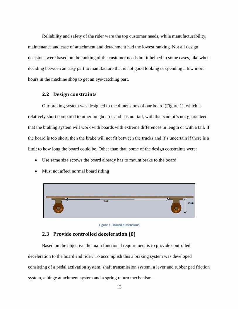
2.2 Design constraints
Our braking system was designed to the dimensions of our board (Figure 1), which is
relatively short compared to other longboards and has not tail, with that said, it’s not guaranteed
that the braking system will work with boards with extreme differences in length or with a tail. If
the board is too short, then the brake will not fit between the trucks and it’s uncertain if there is a
limit to how long the board could be. Other than that, some of the design constraints were:
Use same size screws the board already has to mount brake to the board
Must not affect normal board riding
Figure 1 - Board dimensions
2.3 Provide controlled deceleration (0)
Based on the objective the main functional requirement is to provide controlled
deceleration to the board and rider. To accomplish this a braking system was developed
consisting of a pedal activation system, shaft transmission system, a lever and rubber pad friction
system, a hinge attachment system and a spring return mechanism.

14
2.4 Provide controlled activation (1)
An important functional requirement that contributes to controlled deceleration of the
rider is the ability for the rider to control the amount of braking applied. This requires a system
of activation that allows for variable control over the amount of braking applied while still
allowing normal use of the longboard’s functions. The braking system will provide for control of
the rider’s speed as well as the ability to bring the rider to a complete stop. The acceleration from
braking should be controlled gradually so the rider will not be thrown off the board due to a rapid
change in acceleration. The upper limit of deceleration should be lower than the amount that
would cause the rider to be thrown off the front of the board. The lower limit of activation will
be no braking at all, and the activation will be normally set to this position.
The two major methods of activation that were considered were activation by hand and
by foot. These two methods provide for adequate control with short ranges of motion. There
were two main reasons for choosing a foot activated system. The first is that a frictional braking
system with the ground was chosen, which requires a large normal force to the ground. The
estimated normal force required for a full stop at constant acceleration from 20 mph in 42 ft is
about 105 pounds of force. A hand lever cable assembly might be used, similar to those used in
bicycle brakes, but there is a trade-off between output force and output distance, making it
difficult to achieve both the required force and travel distance of the brake. The other reason is
the concern of having a mechanical connection between the rider’s hand and the board. This is a
concern because it can be considered unaesthetic to have a cable coming off the board, and
because of the possible hazards of the cable getting stuck under the wheels while the rider is
holding onto the other end.
15
2.4.1 Provide for ease of activation (1.1)
The rider must be able to activate the brake so braking can be achieved quickly and
safely. The action required by the rider to activate the brake must be intuitive and he/she must be
able to do it fast enough to accommodate for dynamic situations on the road such as an
upcoming intersection. Several alternatives were considered for activation system.
A pedal located off the surface of the board, similar to the one from the Side Lever Wheel
Brake system in the state of the art, was considered. The advantage of this is that the surface of
the board is left free. The disadvantage is that the foot must be moved off the board in order to
reach it. The motion of the foot off the board to one side will result in a weight shift off the
center of the board, and will cause an imbalance. Although a pedal on the board takes up some of
the space of the surface of the board, it requires less movement of the foot to access than a pedal
off the side of the board. The rider can maintain a more centered stance during breaking as well,
which allows for increased stability.
2.4.1.1 Provide for ability for activation with sliding foot(1.1.1)
Lifting one’s foot off the board while riding, especially while travelling quickly, can
cause the rider to lose balance. Because of this, it is important for the pedal to be activated with a
sliding motion from the foot. Some alternatives were considered in achieving this functionality.
A sloped surface would allow for the rider to move his/her foot onto the pedal using a horizontal
motion of the foot. A collapsible domed surface was considered because it would not only
provide activation with a sliding foot motion, but it would also provide for activation from all
sides, which is the next functional requirement. This concept was never integrated due to time
constraints. A dome on the top surface of the pedal was used because it is simple to manufacture.

16
2.4.1.2 Provide for activation from all sides (1.1.2)
Footing positions (stances) on the board vary among riders. It was important to provide
for the ability to actuate the pedal from all sides. Symmetry in the shape of the pedal can allow
for access from all sides. A circular shape of the pedal was used because it provides for the
ability to use the same motion regardless of the direction that the foot moves from.
2.4.2 Provide resistance to pedal movement (1.2)
If the brake is applied too quickly, the assumption was made that it will cause a spike in
deceleration causing the rider to be forced off the board. This can be quite dangerous and result
in a fall. Resistance must be provided to the pedal movement so that the rider can activate the
system without accidentally applying too much force to the brake, causing the undesired spike in
deceleration. Several alternatives were considered to provide this. Since the lever must be
returned to its original position to keep it in a normally off position, the same design parameter
can be used to fulfill both of these requirements. The resistance force is greater than the force
required to return the brake to its off position. Although coupling is normally avoided, in this
case it’s acceptable because the additional force does not affect the fulfillment of the FR, once
sufficient force is provided to return it, any additional force will not change this.
2.5 Transfer Loads (2)
2.5.1 Transfer vertical loads from foot to sliding friction interface (2.1)
For full activation of the braking system the loads from the rider stepping downward have
to travel to the sliding friction interface. This will provide the friction force necessary to slow or
stop the board and rider.

17
2.5.1.1 Transfer load from foot to pedal (2.1.1)
For the rider to activate the brake with his or her foot there must be a surface on the
activation that can be stepped on. The pressure on this surface will be transmitted downward to
the sliding friction interface through a series of mechanisms. The top surface of the pedal fulfills
this functional requirement.
2.5.1.2 Transfer load from pedal to shaftn(2.1.2)
With the activation pedal being above the board, shaft going through the board, and the
rest of the system being below the board, the shaft must be detachable from the pedal so that the
entire system may be assembled and disassembled on the board. The connection must be secure
so that it stays sturdy during constant vibration of riding and several activations. It must also be
strong enough to withstand the rider’s stepping force. The pedal and shaft could be connected by
inner threads on the shaft and outer threads on the pedal, inner threads on the pedal and outer
threads on the shaft, or a threaded bolt connecting the pedal and shaft in which both would have
inner threads.
Having the shaft and the pedal made of aluminum aided in having the brake be
lightweight while still being able to withstand braking loads and lowering the chance of
corrosion. This brought the problem of not being able to have outer threads on the shaft or pedal.
Aluminum outer threads wouldn’t be able to take the sheer force so either the threads would get
stripped upon activation of the brake or they would deform in such a way that the connection
from the pedal to the shaft is no longer secure. However inner threads are more stable on
aluminum so having a threaded bolt that connects both the pedal and the shaft was the best
solution. The bolt was not only stronger, but could be easily ordered.

18
2.5.1.3 Transfer load from shaft to lever (2.1.3)
With the loads from stepping being transmitted directly downward to the lever from the
shaft, the connection between these two components must be secure. The connection must also
be stable enough to withstand the loads so the transmission happens the same way every time the
brake is applied. The solutions that were considered to solve this problem were (Figure 2):
1. Lever and shaft as one piece
2. Joint connection between the lever and shaft
3. Depression in top of lever face with rounded end at the bottom of the shaft
4. Machine screw through the lever into the bottom of the shaft
Figure 2 - a.) First alternative; b.) Second alternative; c.) Third alternative; d.) Fourth alternative
It was mutually decided that the first two alternatives would be difficult to machine. It’s
best to make the machining process as simple as possible to reduce machining time and cost.
The third alternative had the shaft and the lever disconnected which brought up the issue of how
the shaft was going to stay stable so the activation could be consistent. The machine screw
through the lever turned out to be the best out of the four alternatives and was applied to the final
design.

19
2.5.1.4 Transfer load from lever to rubber pad (2.1.4)
The loads transferred from the lever to the rubber pad transfer automatically upon full
activation because the surfaces are parallel and touch each other. The only requirement for
vertical load transfer was that the pad had to be at least as wide as the lever and long enough so
the lever doesn’t touch the ground unless the pad is completely worn out.
2.5.2 Transfer horizontal loads from sliding friction interface to board
(2.2)
Once the loads from the rider are transferred to the ground, ending at the rubber to
ground interface, a horizontal friction load is created. This load needs to be transferred to the
board so that the rider activating the brake will actually be able to slow or stop the board. There
were two methods accomplishing this (Figure 3):
A system where the shaft is connected to a lever that is connected to the board at a pivot
point and the friction interface is at the bottom face of the lever.
A system where the shaft is connected directly to the friction interface and the back of
that system would push on the rear truck upon activation.
Figure 3 - a) Loads transferred through a lever to board. b) Loads transferred to rear truck

20
The problem with the second system was that pushing on the trucks for a brake would
interfere with riding. The trucks’ connection to the board isn’t rigid as they actually rotate
slightly for turning (Figure 4). It was decided that this design was unacceptable based on the
constraint that the brake must not affect normal riding ability. The levered system doesn’t
interfere with the trucks because it transfers the frictional loads through the lever to a hinge that
would be connected to the board.
Figure 4 - Board with front wheels strait (left) and with wheels slightly turned (right)
2.5.2.1 Transfer load from rubber pad to lever (2.2.1)
In order to be sure that the friction interface transfers the frictional loads to the lever
effectively, the interface must be attached securely to the lever. The solutions found to address
this were to adhere the pad directly to the lever, adhere the pad to a thin rigid plate that would be
bolted to the lever, and bolt the pad directly to the lever. Bolting the pad to the lever was the
best choice because it allowed for the pad to be removed easily if worn out which wasn’t allowed
by adhering directly to the lever. Also, the pad was hard enough (Appendix D) so that it
wouldn’t have excessive deformation to fall off the bolts and could handle the shear stresses so
there wouldn’t be failure in the material if bolted properly.

21
2.5.2.2 Provide hinge for lever (2.2.2)
For the lever to be attached to the board at the lever pivot there must be a proper hinge
system. The hinge must be able to securely connect the lever to the board and be able to
withstand the loads from braking.
2.5.2.2.1 Reduce stress concentrations around pin holder
(2.2.2.1)
The pin holders are two components that will be taking all the frictional loading upon
brake activation and it is critical that stress concentrations are avoided in the design. Stress
concentrations can be detrimental in the design of the pin holders as they can cause cracks and
failure at locations where there are sharp corners or abrupt changes in the cross section. These
locations bring all the stress to one point and actually act as amplifiers for the stress (Noble,
1997). Chamfering the outer corners and filleting the inner corners would better disperse the
stress in the structure.
2.5.2.2.2 Provide for tight fit around pin in the pin holder
(2.2.2.2)
Because the braking system would be on a system that was in motion most of the time,
the team agreed that it would be best to minimize moving parts in the brake while still being
effective. This meant that the pin (mentioned in section 2.5.2.3) would have to be fixed in either
the lever pivot hole or the pin holders. Having the pin fixed to one of these structures would also
keep the pin fixed to the system so it doesn’t come apart and cause failure. Because either
fixture would yield similar results the decision was made to have the pin fixed in the pin holders.
To accomplish this, the tolerance of the hole in the pin holder was made to be +0.006in (Lieu &

22
Sorby, 2009). This dimensional tolerance would provide a tight fit around the pin keeping it
secure.
2.5.2.2.3 Provide for smooth sliding around pin in the lever
(2.2.2.3)
With the brake undergoing constant use there will be constant rubbing between the pin
and the inner surface of the lever pivot point. This being said, there must be as little friction as
possible to allow for smooth rotation about this point as well as to lower the chance of corrosion.
The solutions considered to address this problem were to use copper bushings or to have nylon
bushings. Although both solutions would provide smooth sliding around the pin and reduced
chance of corrosion the nylon bushings were easier to find and cheaper to buy or replace if
needed. Regardless of what type of bushings used, the hole in the lever pivot point had to be
tight around the bushings so the tolerance of the hole was made to be an interference fit.
2.5.2.3 Transfer load from lever to pin holder (2.2.3)
In order for the hinge mechanism to be complete for the brake there must be a pin that
connects the pin holders to the lever pivot point. This pin must be inexpensive and able to
withstand the loads from braking. It was decided that a shoulder bolt pin would work because it
was cheap, easy to order and therefore reduced the amount of machining, and could withstand
the braking loads. The shoulder on the pin along with the other end of the pin being threaded
allowed for the pin to be secured in the system with a nut ensuring it won’t fall out after constant
use.

23
2.5.2.4 Transfer load from pin holder to board (2.2.4)
Transferring the braking loads to the board is crucial for the design to actually bring
deceleration to the board and rider. It was possible to adhere the pin holder to the board, tie the
pin holder to the board, or bolt the pin holder to the board. Bolting the pin holder to the board
was the best design parameter because it allowed for the brake to be detachable from the board if
desired and the bolts could efficiently transfer the braking loads to the board and therefore cause
the board and rider to decelerate. Due to the design constraints that the brake must not interfere
with normal riding ability and that the board mounting must use standardized parts the bolts
chosen for this were 10-32 countersunk screws.
2.6 Optimize sliding friction interface (3)
To stop the longboard from moving, friction has to be applied to either the ground or
wheels. The team assumed that a system that applies friction to the wheels is able to stop the
longboard smoothly since the wheels are rolling over the ground, but if too much friction is
applied then the wheels will stop spinning making the board skid or make the rider fall. Also,
friction on the wheels will cause the wheels to wear faster than normally. On the other hand, if
friction is applied to the ground the board might not stop as smoothly (depending on the surface
of the ground) but the board will not skid because the wheels will continue to spin. The decision
was made to use a rubber pad that applies friction to the ground, because a design that applies
friction to the wheels would most likely need alteration to the trucks.
2.6.1 Optimize contact surface between rubber pad and ground (3.1)
Ideally the rubber pad should be parallel to the ground when the brake is activated. Since
the rubber pad is attached to the lever, this directly affected the design of the lever. The two
alternatives were to design a straight lever with an angled brake pad or a curved lever with a

24
rectangular braked pad (Figure 5). Although the straight lever would’ve been easier to machine,
the rubber pad wasn’t optimal shape because it would wear faster on the thinner end. The
conclusion was made that the curved lever was the better choice in order to optimize contact
surface between the rubber pad and ground.
Figure 5 – Straight lever vs. Curved lever
2.6.2 Reduce wear of rubber (3.2)
The rubber pad could’ve been small because the friction force doesn’t depend on the
surface area, but heat dissipation and wear had to be taken into consideration. To reduce wear,
the rubber pad was made wide enough for the heat to dissipate more efficiently and because,
intuitively, the team believed that a larger contact surface area would make the pad last longer.
Also, the width of the rubber pad would provide stability to the brake. Because of the limited
time of the project, no detailed analysis was done in order to optimize the size of the rubber pad.
2.6.3 Provide removable interface (3.3)
Given that the wear of the rubber pad is inevitable, an important functional requirement is
to provide the ability to replace the rubber pad whenever it wears down. The detachable rubber
pad has to be easy to replace, yet it should be reliable and not unfasten while the brake is being
used. The decision was made to use bolts on the side of the rubber pad to attach it to the lever.
One alternative was to glue the rubber pad to a removable metal plate, but this idea was
discarded because it was relatively complicated with no improvements in the final result. What

25
size bolts and how many were needed to attach the rubber pad to the lever will be discussed in
section 3.5.
2.6.4 Minimize the effects of inconsistent ground surface (3.4)
Again, inconsistency in the ground surface is inevitable unless the user is riding the long
board in a skate park. One of our assumptions was that bumps in the road could become
dangerous if the brake was activated accidently because the rubber pad touched the ground. The
team believed that a curved rubber pad surface would provide gradual contact with the ground
thus minimizing the risk of the brake being activated accidentally.
2.6.5 Provide consistent braking while turning (3.5)
Another of our assumptions was that braking while turning is a necessity in order to
provide a controlled ride. To provide consistent braking during cornering the maximum tilt of the
board while turning was calculated to be 17 degrees, hence, 17 degree chamfers were added on
both sides of the rubber pad to provide a consistent braking surface.
2.7 Provide path from shaft to lever (4)
It was mutually decided that the loads from stepping would be transferred normally from
the pedal to the shaft. This being said, there must be a pathway on the board for this load transfer
to be possible. This pathway must be short, simple and controlled.
2.7.1 Simplify path (4.1)
The lever arm, which is under the board, has to connect to the pedal which is on the top
of the board. One alternative was to design system that went around the board, but it would’ve
had too many moving parts making the system complicated. Some other alternatives included
using magnetism and electricity in order to not have to perforate the board, but again, it would’ve

26
been complicated and perhaps unreliable. Keeping in mind the customer need of low cost, the
previously mentioned solutions were discarded. The assumption was made that a hole less than
1.00in diameter through the board shouldn’t change the board’s functionality. Therefore, a hole
big enough for the stem of the pedal to go down, but small enough so that the shaft doesn’t go up
was drilled.
2.7.2 Reduce Wobble (4.2)
Since the diameter of the bottom of the pedal is smaller than the diameter of the hole
through the board, the pedal had some free space to move in undesired directions. To prevent this
undesired motion a grommet was used to cover the hole on the board. At the same time it would
make the hole an oval shape preventing the shaft from moving in undesired directions, as shown
in the figure below.
Figure 6 - Hole before and after grommet
2.8 Provide for adjustable clearance under the board (5)
Adjustable clearance under the board is necessary to account for varying rider weights,
wheel sizes and trucks. Alternative methods for achieving this in the design were considered.
Interlocking pipes with a clamp would resemble the system used to adjust the height of seat post
of a bike. The interlocking pipes could also be adjusted with coinciding holes in the pipes. These
could be fixed in place with a pin.

27
The interlocking pipe system was an idea, but was never fully developed. A threaded
interface was chosen because it could be integrated into the existing shaft design easily. 0.5in of
clearance was achieved with this system. This was enough adjustability to account for the wear
of the pad but not the other varying factors.
2.9 Provide for normally off position (6)
During normal riding the brake must be set in a normally off position because it is desired
that no braking should occur until activated by the rider. Several alternatives were considered to
provide this functionality. One consideration was torsion springs attached around the pin and
connected to the lever (Figure 7).
Figure 7 – Torsion spring return system (front view)
A cantilever spring that interacts between the underside of the board and the lever was
also considered (Figure 8). A strip of metal attached to the lever would act as a cantilever spring
and return mechanism.
Pin Holders
Torsion Springs
Lever
Deck
Pin

28
Figure 8 – Cantilever spring return system (side view)
Extension springs attached to the underside of the board were ruled out because they are
unaesthetic, and would require a fixture to the underside of the board. Minimizing the amount of
board modification was taken into consideration. The decision was made to use a conical
compression spring that sits between the pedal and the board. A conical spring has a low
compressed length and can keep the pedal at a lower height above the board in its uncompressed
state. Calculations for the preload on the spring necessary to hold up the transmission and lever
can be found in Appendix H.
Lever
Cantilever
spring

29
3 Physical Integration and Finite Element Analysis
This section shows what the parts physically look like and how each FR is met through
each component. Appendix B shows the decomposition of each of FR followed by figures
pointing them out in the actual design. Figure 9 shows the assembly of the braking system with
all the components attached and it should help visualize the purpose of each component when
they are discussed in more detail later in this section.
Figure 9 - Braking System Assembly
This section also contains the finite element analysis conducted prior to machining the
major load bearing components of the system. These components were the pedal, shaft, pin
holders, rubber pad and pin. Other components like the spring are also discussed in this section,
although finite element analysis was not necessary. Components were constrained according to
the mounting conditions and stresses were verified to ensure that no component exceeded the
yield stress of the material. Deflections were observed to ensure the component did not deflect to
an extent as to inhibit proper functionality. Unless otherwise specified, all the components are
made of Aluminum 6061-T6. The yield strength for this material is 40 ksi. The reason the team

30
choose this material is because it is the most common metal used in the school because of its
material properties and the relative low price.
3.1 Pedal
The pedal is the only component that the rider interacts directly with to activate the brake.
The functional requirement that the pedal satisfies are to provide ease of activation by being able
to be activated by sliding the foot and being able to be activated from all sides. In order to
activate with sliding foot the pedal has a dome shape and is symmetric from all sides. Some other
functional requirements satisfied by the pedal are to provide an upper limit for the spring and to
transfer the loads to the transmission system, as illustrated in Figure 10.
Figure 10 - Pedal FR's and DP's
Again, before machining this part finite element analysis was conducted in order to find
the safety factor of the component. The team decided to design the pedal to be able to support the
force of someone actually jumping on the pedal. This is not the correct way to use the pedal, but
just in case a user decided to test the strength of the pedal it was designed to withstand high
loads. Using a force plate from the Physics Department at WPI, we found the average force when
landing was around 330 pounds of force, so this is the force we applied to the pedal. The safety
factor was 6.4, meaning it could sustain the force of a user jumping on the pedal.

31
Figure 11 - Pedal FEA (Factor of Safety)
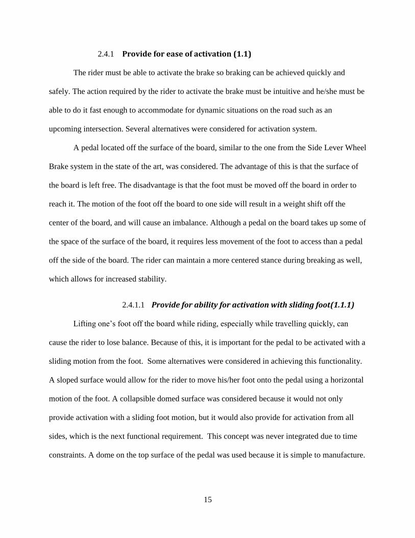
3.2 Spring
The spring’s main function in the brake was to return it to an “off” position so it would
deactivate once the rider wasn’t stepping on it. This added control to the rider so he could
activate and deactivate the brake at any time. It does this by resting between the pedal and the
board (Figure 12), providing an upward force upon compression that will bring the pedal back up
once there is no longer a stepping load. This slight resistance against the stepping force also
grants control to the rider. This means that the brake isn’t fully activated when the pedal is
stepped on and the rider can decelerate as gradually as he needs. The spring constant of the
spring was 7.81 lbf/in.
Mesh type Solid Mesh
Element size 0.082928 in
Number of elements 7393
Number of nodes 12510
Min stress 2.8 psi
Max stress 6.213 ksi
Table 3 - Pedal FEA Summary
32
Figure 12 - Spring
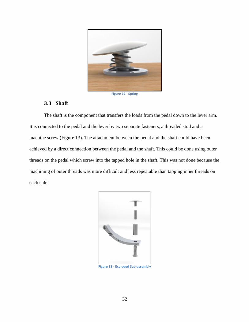
3.3 Shaft
The shaft is the component that transfers the loads from the pedal down to the lever arm.
It is connected to the pedal and the lever by two separate fasteners, a threaded stud and a
machine screw (Figure 13). The attachment between the pedal and the shaft could have been
achieved by a direct connection between the pedal and the shaft. This could be done using outer
threads on the pedal which screw into the tapped hole in the shaft. This was not done because the
machining of outer threads was more difficult and less repeatable than tapping inner threads on
each side.
Figure 13 - Exploded Sub-assembly

33
The shaft also provides adjustable clearance between the pad and the ground using two
locknuts between the machine screw and the shaft. The shaft can turn along the machine screw
and be locked into position using the locknuts.
Plain carbon steel (Appendix F) was used for the shaft, the stud, and the machine screw.
This material was used because it was easily available for use in the prototype, and can hold
threads better than aluminum can. In terms of corrosion this material is not optimal, as steel will
certainly corrode in a wet environment. The interface between the aluminum pedal and the steel
stud will also introduce galvanic corrosion.
To ensure that the shaft and the fasteners could withstand the stepping loads placed on it
during braking, FEA was performed on the assembly. A load of 200 lbs was placed on the top
surfaced of the pedal at a slight angle to simulate a rider’s weight being placed onto the brake.
This is a higher load than will be experienced during braking, but the system should be able to
withstand a rider standing on it without yielding. Stress concentrations appear in the threaded
rod, and the minimum safety factor for the system was 2.57 as can be seen in Figure 14.
Figure 14 - FEA of assembly of pedal, shaft, and lever

34
Mesh type Solid Mesh
Element size 0.15149 in
Number of elements 15612
Number of nodes 25595
Min stress 3.28 psi
Max stress 12.372 ksi
Table 4 - Shaft sub-assembly FEA summary
3.4 Lever arm
The lever is the rotating member that transfers the normal loads from the shaft to the
rubber pad creating a friction load on the ground. At the point where the shaft transfer’s stepping
loads to the lever there is a hole in the lever for a bolt assuring connection in activation and
return position. This member is securely connected to the rubber pad with side bolts so these
friction loads get transferred to the board by means of a hinge mechanism. The curved shape of
the lever provides an optimized contact surface between the rubber pad and the ground so when
the brake is fully activated the flat surface of the pad is flush with the ground. The hole in the
lever pivot point was given an accurate tolerance so that the bushings would fit tightly in those
holes preventing sliding. Figure 15 below shows the lever and features that satisfy these
functions.
Figure 15: Lever with labeled features

35
Finite element analysis was performed on the lever to see how it would handle the
stresses from the friction loads that would be created upon braking. 200lbs of force were applied
to the surface where the shaft would be attached and 100lbs of force were applied to each of the
holes where the bolts would be. The safety factor was 14.
Figure 16 - Lever FEA
Mesh type Solid Mesh
Element size 0.16902 in
Number of elements 9113
Number of nodes 15185
Min stress 6.51 psi
Max stress 2.757 ksi
Figure 17 - Lever FEA Summary
3.5 Rubber Pad
The rubber pad’s functional requirements are to transfer load from rubber pad to lever,
optimize contact surface between rubber pad and ground, reduce wear of rubber, provide
removable interface, minimize the effects of inconsistent ground surface and provide consistent
braking while turning. Since the lever and the rubber pad are directly connected, the functional
requirements optimize contact surface and reduce wear of rubber are satisfied by the lever being
curved and wider where the rubber pad is attached, respectively. The other functional
requirements are met by the rubber pad’s design. To transfer the load from the rubber pad to the

36
board and to provide a removable interface the rubber pad has 4 holes that attach it to the lever.
In order to minimize the effects of inconsistent ground surface the rubber pad is curved so it can
glide smoothly over little obstacles in the ground. To provide consistent braking while turning
the rubber pad has 17 degree chamfers on the sides. Figure 18 below shows the rubber pad with
it’s functional requirements and design parameters that meet them.
Figure 18 - Rubber Pad FR's and DP's
During the design of the rubber pad, it was necessary to know what size holes and how
many will be necessary to make sure that the rubber wouldn’t fail while it was being used. Using
the SolidWorks finite element analysis feature, the team found that four holes of 0.1275in
diameter (two on each side) would be sufficient to hold the rubber pad in place without it failing.
The team applied a shear force of 100lbs to the bottom of the rubber pad while making the holes
the restraints. The safety factor was found to be 2.08. Figure 19 and Table 5 below show the
results.

37
Figure 19 - Rubber Pad FEA
Mesh Type Solid Mesh
Element Size 0.176 in
Number of elements 8715
Number of nodes 14321
Min Stress 3.46psi
Max Stress 1.022ksi Table 5 - Rubber Pad FEA Summary
3.6 Pin Holder
There are two pin holders and their main function is to provide a hinge for the lever.
Their other functional requirements are to transfer loads to the board, reduce stress
concentrations and provide a tight fit for the pin. To transfer loads from the pin holder to the
board two 0.19in diameter holes were drilled in order to attach each pin holder to the board with
10-32 fasteners. The locational clearance fit was accomplished by designing the hole for the pin
with tight tolerances and stress concentrations were reduced by providing rounds of 0.5in
diameter. Figure 20 below shows the design parameters that fulfill each of these functional
requirements.

38
Figure 20 - Pin Holder FR’s and DP’s
To ensure the pin holders could sustain the loads without failure a finite element analysis
was done in SolidWorks. The force used was 200lbs, which is 4 times higher than the maximum
force the team calculated was needed to brake. The safety factor was found to be 5.76. Figure 21
and Table 6 below summarizes the results.
Figure 21 - Pin holder FEA
Mesh type Solid Mesh
Element size 0.0972 in
Number of elements 7793
Number of nodes 12481
Min stress 0.069 psi
Max stress 932.28 psi
Table 6 – Pin Holder FEA Summary

39
3.7 Pin and nylon bushing
The function of the pin is to transfer loads from the lever to the pin holder. The pin also
provides for rotation of the lever. A threaded shoulder bolt was used for the pin so that it could
be prevented from moving axially. At one end the head of the shoulder bolt prevents axial
translation, and at the other end a nut (not shown) is screwed on to the threaded end of the
shoulder bolt. The material used was zinc plated steel (Appendix G).
Figure 22 - Threaded shoulder bolt (pin)
The nylon bushings provide for a proper sliding interface between the pin and the pin
holders. They also provide a barrier between the dissimilar metals of the pin and the pin holder
which prevents galvanic corrosion. FEA was performed on the pin to ensure that it can handle
the loads without yielding. Figure 23 and Table 7 show a summary of the results
Figure 23 - Pin FEA
Mesh type Solid Mesh
Element size 0.12832 in
Number of elements 8792
Number of nodes 14430
Min stress .117 psi
Max stress 1.604 ksi
Table 7 - Pin FEA Summary
40
4 Prototype Production
4.1 Milling
In the production of our prototype two parts had to be milled and fixtured. Due to the
complexities in shape of these parts to be milled, special fixtures needed to be designed and
milled as well. Throughout this process there were several problems that occurred as foretold by
the project advisor; most of which were solved, but some merely served as educational
experiences.
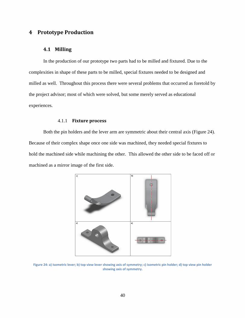
4.1.1 Fixture process
Both the pin holders and the lever arm are symmetric about their central axis (Figure 24).
Because of their complex shape once one side was machined, they needed special fixtures to
hold the machined side while machining the other. This allowed the other side to be faced off or
machined as a mirror image of the first side.
Figure 24: a) Isometric lever; b) top view lever showing axis of symmetry; c) isometric pin holder; d) top view pin holder showing axis of symmetry.

41
The pin holder had a flat bottom and a rounded top. Regular soft jaws were sufficient to
fixture the part for machining the first side, but once that side was machined one of the soft jaws
were machined to hold the round side of the part. In order to effectively fixture the rounded
feature on the pin holder, there needed to be more than one point of contact in that fixture. This
was accomplished by making a “V” indent on the soft jaw that would be on the rounded side
(Figure 25).
Figure 25: Machined soft jaw with transparent pin holder.
Because the lever had a more complex shape, a more complex fixture (Figure 26) had to
be developed to hold it to machine the other side. With the way the lever is shaped it wasn’t as
simple as to design jaws that came in from positive and negative y-axis. There was a concern
with the elastic deformation during machining that would prevent the mirror machining. To
prevent this deflection, the fixture was designed to have a base that two vice grips would
approach from the positive and negative y-directions and from the base a connected rod that goes
through the pivot point of the lever with a tight fit. There is an extrusion from the base that
interfaces with the top face of the lever and the vice grip acting as an extension of the vice grip to
the work piece. The part of the base where the rod is located interfaces with both the positive
and negative approaching vice grips. This fixture acts as a locator to assure the part is in the

42
correct position relative to the tool for machining. The vice grips come in from the positive and
negative y-axis to apply force that keeps the part and fixture in position during machining.
Figure 26 - (left) Orientation of vice grips relative to fixture device (right) Fixture and part with labeled interfaces
4.1.2 Problems
It was advised that the machining of the prototype be started as soon as possible before
the project due date to ensure there was enough time to deal with machining problems if any
arise. This was a good consideration because there were several issues that came up within the
process of trying to manufacture the prototype such as machine time, tooling, error in stock
measurement, and machining for desired tolerances.
4.1.2.1 Reduce machining time
When the first side of the lever arm was machined it was decided to have to the main
shape of the lever machined using a contouring operation. The problem with this was that due to
the shape of the lever and the stock used there was a lot of air machining and this made the
machine run for over three hours just on that one side. To improve this process for the other side
instead of using a contouring operation to create the main shape of the lever, a pocketing
operation was used having the lever as an island and the outer edges of the stock as open edges

43
(Figure 27). This eliminated all the air machining and greatly reduced machining time to be
around a half hour.
Figure 27: a) contouring first side showing unnecessary tool path; b) pocketing operation of second side of lever.
4.1.2.2 Proper tooling for hole operations
When machining the pin holders it was found that a chamfer mill may not be the best
choice for drilling holes. This may be sound obvious to a more experienced machinist, but being
novices this wasn’t immediately obvious. The first pin holder’s hole was machined 0.75in deep
using a 0.375in chamfer mill without any problems. Using the same tools and the same program,
from ESPRIT, on the second part the chamfer mill plunged into and got stuck in the work piece.
After some advice from experienced lab monitors the program was changed so the hole operation
was spotted with the chamfer mill and drilled with a 0.375in drill bit instead.
4.1.2.3 Error between stock size and model in machining
When going from the modeled simulation of machining operations to actual machining
for parts such as the pin holders and the fixture device for the lever arm there was an issue of
extra material being left behind from some facing and contouring operations. After a facing
operation on the pin holder and a contouring operation on the fixture device there was a thin
44
sheet of metal left over in an area where there was expected to be nothing. This may have been
due to human error in measuring the stock for these parts because the stock wasn’t faced on all
sides assuring parallelism between opposite sides and perpendicularity between adjacent sides.
These pieces of extra material were able to be pulled off without damaging any critical features.
In the future, measuring of the stock piece should be done more accurately.
4.1.2.4 Tolerances for holes
After machining the pin holders the holes in the pin holders were observed to have a
different fit on the pin than desired. The tolerance on these holes intended for a locational
clearance fit so that the fit would be tight on the pin holders preventing motion of the pin, but
still allow for hand assembly. There was an agreement between the group that this wouldn’t be
detrimental to the final product and due to the difficulty in getting machine time there wasn’t
another attempt to re-machine them. This acted as a lesson for machining the lever pivot point
so that hole could have the desired tight tolerance. It was found that reaming was a more
accurate machining process for tight tolerance holes. Knowing this, the lever pivot point was
drilled with a 0.4844in drill and reamed with a 0.5in reamer. This resulted in a press fit for the
nylon bushings in the lever pivot point.
4.2 Turning
Two of the components in the braking system were manufactured on a CNC lathe
because of their cylindrical symmetry: the shaft and the pedal. Both operations were fairly
simple, not requiring any special fixtures or tooling. However, the order of machining processes
for the pedal was significant in order to ensure that it could be fixed properly at each step. The
only significant issue encountered in the machining process was the use of a relatively long drill
bit in the drilling of the hole in the pedal. Using a bit that is longer than necessary is undesirable
45
because it causes extra drill wander, which negatively affects tolerances. Since the hole drilled
was going to be tapped, the tolerance on the diameter of the hole was not critical.
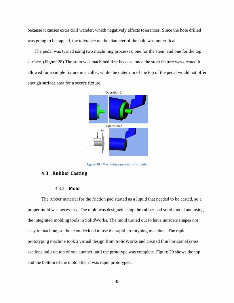
The pedal was turned using two machining processes, one for the stem, and one for the top
surface. (Figure 28) The stem was machined first because once the stem feature was created it
allowed for a simple fixture in a collet, while the outer rim of the top of the pedal would not offer
enough surface area for a secure fixture.
Figure 28 - Machining operations for pedal
4.3 Rubber Casting
4.3.1 Mold
The rubber material for the friction pad started as a liquid that needed to be casted, so a
proper mold was necessary. The mold was designed using the rubber pad solid model and using
the integrated molding tools in SolidWorks. The mold turned out to have intricate shapes not
easy to machine, so the team decided to use the rapid prototyping machine. The rapid
prototyping machine took a virtual design from SolidWorks and created thin horizontal cross
sections built on top of one another until the prototype was complete. Figure 29 shows the top
and the bottom of the mold after it was rapid prototyped.

46
Figure 29 - Rapid prototyped mold
The team decided to use 60A liquid urethane for the rubber pad because of the material
properties (Appendix D). Since the molds were made out of ABS plastic it was ensured that the
urethane could cure at room temperature. Since we had no molding experience we asked for the
help of Kenneth Stafford, a robotics’ team advisor with experience molding the same urethane as
our brake pad would be made of. He advised to add breathing holes to the mold and to pick a non
critical surface of the mold to pour the rubber in because bubbles will form on the top of the
mold. He has tried getting rid of the bubbles by using vibrations and other methods, but all
methods failed to get rid of the bubbles completely.
4.3.2 Casting
4.3.2.1 Prerequisites:
Following Kenneth’s advice the team had to find the best place to inject the urethane,
how many injection holes were needed and their sizes. The team decided that the least critical
part of the rubber pad was the surface that touched the lever, so the injection holes were placed

47
there. We had no real mathematical methods to find out how many injections holes or what size
were needed, so we made the assumption that two 0.25 in diameter holes would suffice. The
team also needed to find how many breathing holes were necessary, but we ran into the same
problem as stated before. Again, we assumed that the more holes the better so we drilled holes at
random of 0.125in diameter. Determining the volume of the part and the amount of urethane
needed to mix were other requirements for the casting process. We used the mass properties from
SolidWorks to find the volume of urethane needed. Also, metal studs were found the same
diameter as the holes we planned to have on the rubber pad. The liquid urethane will not stick to
the metal studs, so once the mold was dry we could remove the pins, leaving the desired holes.
4.3.2.2 Materials:
Materials needed for the casting included (Figure 30):
Needle-less syringe, to inject the urethane into the mold
Measuring cups, to make sure the proportions of the mixing are exact
Silicon spray to make sure the mold is lubricated and rubber won’t stick
Metal studs, for holes
Mold top and bottom
Figure 30 - Materials for rubber casting

48
4.3.2.3 Procedure
1. Spray the silicon on the mold and make sure it is well lubricated
2. Spray silicon on the metal studs and put them into the holes inside the mold
3. Mix for 2 minutes maximum, because instructions said that the rubber would start curing
in 10 minutes, so we figured that 8 minutes of injecting should be enough
4. Use the syringe to put the urethane mixture inside of the closed mold.
5. Leave it closed for about 8 hours, but it wouldn’t be fully cured for at least a week.
4.3.3 Problems
As expected, the team ran into many problems during the casting process. First, the
syringe was too small and the mixture was much denser than expected so it was very difficult to
inject the mixture. In fact, the urethane started curing inside of the syringe so we couldn’t use it
anymore (Figure 31). When the syringe became useless, 10 minutes had already passed so all of
the liquid urethane was already dried. When we opened the mold we noticed that we didn’t
accomplish much by injecting the urethane because it was pretty much empty inside.
Figure 31 - Dried rubber inside syringe
4.3.4 Casting (Second Try)
With our knowledge of the previously failed casting experiment the team decided to try
the casting again but with a different technique. Instead of injected the liquid urethane, we
decided to make a box the same size as the mold in order to fit the bottom side of the mold in it.
The box was much taller than the mold because our strategy was to pour all the urethane into the
box and then put the top of the mold on top and close it. This strategy was messy but it prevented

49
the mold from curing before we had the chance to pour it all in. As shown in Figure 32 the
rubber pad casted very well, but in Figure 33 it can be seen that the casting wasn’t perfect
because the corners are missing. This corner was important because this is where the screws
holes were suppose to be, but team decided that this cast was good enough and that we could
work around that by making screws holes elsewhere.
Figure 32 - Rubber Pad casted
Figure 33 - Rubber Pad missing piece
4.4 General Assembly
To assemble the completed prototype (Figure 34) three sub-assemblies had to be
assembled. These assemblies were the pedal-sub, the lever-shaft-pad-sub, and the board-sub.
Figure 34: Exploded assembly of brake system showing all parts without board

50
4.4.1 Lever-shaft-pad-sub
For the lever-shaft-pad-sub (Figure 35) the bushings were pressed into the lever pivot
point. One of the bushings was cut ~0.25in shorter so both of them could fit. Once these
bushings were pressed in place they were difficult to take out without defecting them. A
machine bolt was screwed through the other hole of the lever, from the bottom, and a shaft on
top of the lever screwed tightly. The pad was place around the bottom of the lever so the curve
of the pad followed the curve of the lever and was bolted on the sides.
Figure 35: Lever-shaft-pad-sub
4.4.2 Pedal-return-sub
To assemble the pedal-return-sub (Figure 36) the threaded bolt was tightly screwed
through the stem of the pedal. The spring was placed around the stem of the pedal with the small
diameter of the spring touching the bottom face of the pedal and the large diameter away from
that face.
Figure 36: Pedal-return-sub

51
4.4.3 Board-sub
In order to make the holes in the board for the board-sub a positioning assembly needed
to be built. To do this the pin holders were placed on both sides of the lever pivot point of the
lever-shaft-pad-sub and the pin was put through the pin holders and fixed with a nut on the
threaded end of the pin. This positioning assembly was placed on the bottom of the board near
the back truck with the pin holders in front and lever in back. Once the positioning assembly
was in place, the location of the 0.19in holes, for the fixture bolts, and a 1.25in hole, for the
grommet, were marked and drilled. The 10-32 machine bolts and grommet were then put into
place from the top completing the board-sub.
Figure 37: (left) position assembly placement; (right) board-sub
4.4.4 Final assembly
The pin holders were taken off the lever and put on the bolts under the board without nuts
in place. This was done to keep the pin holders loose for proper placement of the lever-shaft-
pad-sub, accounting for the curve about some boards’ axis of motion. The lever-shaft-pad-sub
was the placed between the pin holders and pin was placed through the pin holders similar to
Figure 37. Nuts were tightly applied to the bolts and threaded pin. The pedal-return-sub was
then screwed into the top of the shaft from the top of the board so the board is between the shaft
and return mechanism. Once the final assembly was complete the pedal was pressed a few times
to test the brake motion before riding.

52
5 Testing and Analysis
Testing was performed to verify that the braking system meets its functional requirements
and to measure its performance. The braking system was tested for normal ride-ability by several
volunteers as well as the team members. Stopping distance testing was also carried out using the
breaking system and a foot braking method. Critical dimensions of components in the system
were also measured to see how well they met the desired tolerances.
5.1. Functional Requirement testing
Once the board and braking system were assembled, each component was tested for
functionality. A temporary machine screw was used for attaching the rubber pad because of the
casting problems (section 4). Most of the components passed the functionality test, except the pin
and the spring which were satisfactory because they performed their function with minor flaws.
Two of the components failed, which made the braking unusable. Table 8 below shows the
summary of the test.
Component Result Comments Picture
Lever Arm Passed
Pin holders Passed
Pedal Passed
Nylon
bushings
Passed
Pin Satisfactory The thread doesn’t go all the way
through the pin holder.
Spring Satisfactory Not stiff enough, goes in hole
and wobbles.
Shaft Fail Too long (when rider steps on
board the brake pad touches the
ground because of the deflection
of the board)
Slight Corrosion on threads.
Rubber pad Fail Temporary attachment screw
touched the ground before the
pad.
Table 8 – Initial functionality test results

53
In the figures in Table 8, the top of temporary screw can be seen before the test painted
with the red marker and after the test with the marker scratched off from having contact with the
ground. Also, the rubber pad can be noticed almost touching the ground with no rider on the
board because the shaft was too long.
At this point testing the brake as a system was not possible until the two components that
failed could pass the functionality test. A short term solution was identified in order to test the
performance of the brake as a system, but the failed components will need to be iterated and
redesigned.
5.1.1 Solution for testing braking function
Modifications were made to the prototype so that the braking functionality could be
tested relatively quickly. The machine screw that the shaft attaches to was shortened, and the
locknuts were removed, consequently removing the ability to adapt the clearance of the pad from
the ground. The threaded rod that attaches the shaft to the pedal was lengthened. The temporary
machine screw holding the pad was replaced by adding two additional holes on each side of the
rubber pad, for a total of six screws.
5.1.2 Initial riding test results
During the initial riding test, the front surface of the brake pad ran into a bump on the
ground. This can be fixed by bringing the surface of the pad higher on the lever, and tapering the
part of the pad that doesn’t contact the ground so that it ends flush with the lever surface. The
spring rate was not high enough to provide comfortable control over the braking. The positioning
of the pedal on the board affected normal riding because it was found to be a natural position for
the rear foot to be placed during riding. At higher speeds the braking was found to be quite
consistent, but at lower speeds it became less constant and more subject to jerkiness.
54
5.2. Normal riding test
We had several volunteers try the brake and give feedback on how it felt to ride the board
with the brake, and the functionality of the brake. Some users reported that the brake is too
sensitive (so did we) but we got used it quickly. The main reasons for the high sensitivity can be
attributed to a spring that is not stiff enough to provide proper resistance to the rider’s weight.
Also, the brake pad material is too soft, which causes sharp spikes in deceleration at lower
speeds due to the pad catching on the road surface. Users could ride the board normally, but the
presence of the pedal on the board surface was something that required a conscious effort to
avoid. Because the longboard used for testing is relatively short, the pedal occupies a space that
is a natural footing position. It is simple to adjust to a stance with the foot in front of the pedal,
but this shortens the rider’s stance, which decreases his/her stability. One of the major problems
during testing was that different stances and different rider weights cause varying board flexes,
which changes the clearance of the pad above the road. The pad was observed to hit the ground
while going over large bumps and cracks in the ground. The variability in clearance based on
rider weight and stance calls for a larger amount of adjustability than was originally designed for.
This will be discussed further in chapter 6 in the iterations section.
5.3. Stopping distance testing
The stopping distance test was performed to compare our braking system with the foot
braking method (Figure 38). Both braking methods were executed on the same hill and were
analyzed based on stopping distance and stopping time.

55
Figure 38 - (left) braking with braking system, (right) braking with foot
5.1.3 Method
Markings were placed at 2 ft intervals along the road (see Figure 39) so that the position
of the board could be determined from video footage. For the braking system, the team
conducted 3 trials with the same user to get an initial velocity at the designated marking where
the user would start braking. The initial velocity was taken as the average velocity over 6ft. The
initial velocity averaged over the three trials was approximately 19.8 ft/sec. For the foot braking
test, the user started from the same place as in the braking system test, but started braking before
getting to the designated marking as a precaution to prevent falling. The intention was to have
identical initial velocities for all tests, but they ended up varying slightly.
Figure 39 - Markings along the road in the testing area

56
To obtain a position plot from the video, data was taken every 5 frames on the video and
the position was recorded using the tape markings. The position of the board was recorded at
each point to within a 0.5ft resolution based on the perspective and clarity of the video. Since the
camera was fixed at the bottom of the hill, the markings were clearer as the rider passed the
location of the camera; hence a 0.2ft resolution was available.
5.2 Results
With the data from the video, position vs. time plots were made in Excel (Figure 40). From these plots, fourth order polynomial regression lines were obtained (
Table 9) and plotted. These functions were then derived and plotted using MathCad to obtain
velocity and acceleration functions of time.
Figure 40 - Position vs. time plots for stopping distance test
Foot Brake - 1 y = -0.0957x4 + 0.6755x
3 - 3.8554x
2 + 21.129x - 0.0129 R² = 0.9997
Foot Brake - 2 y = 0.2366x4 - 2.1318x
3 + 3.0077x
2 + 19.248x - 0.1588 R² = 0.9997
Braking System - 1 y = -0.3352x4 + 1.0706x
3 - 3.8476x
2 + 18.203x - 1.0186 R² = 0.9997
Braking System - 2 y = 0.2104x4 - 1.265x
3 - 0.7024x
2 + 17.112x + 0.038 R² = 0.9995
Table 9 – Regression functions for position vs. time from stopping distance tests
05
10152025303540455055
0 1 2 3 4 5
Position (ft)
t (seconds)
Position vs. Time During Braking
Braking System - 1
Foot Brake - 1
Foot Brake - 2
Braking System - 2
Poly. (Braking System - 1)
Poly. (Foot Brake - 1)
Poly. (Foot Brake - 2)
Poly. (Braking System - 2)
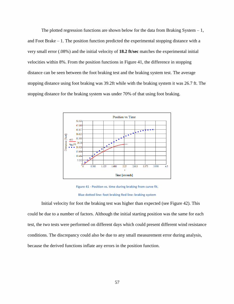
57
The plotted regression functions are shown below for the data from Braking System – 1,
and Foot Brake – 1. The position function predicted the experimental stopping distance with a
very small error (.08%) and the initial velocity of 18.2 ft/sec matches the experimental initial
velocities within 8%. From the position functions in Figure 41, the difference in stopping
distance can be seen between the foot braking test and the braking system test. The average
stopping distance using foot braking was 39.2ft while with the braking system it was 26.7 ft. The
stopping distance for the braking system was under 70% of that using foot braking.
Figure 41 - Position vs. time during braking from curve fit.
Blue dotted line: foot braking Red line: braking system
Initial velocity for foot the braking test was higher than expected (see Figure 42). This
could be due to a number of factors. Although the initial starting position was the same for each
test, the two tests were performed on different days which could present different wind resistance
conditions. The discrepancy could also be due to any small measurement error during analysis,
because the derived functions inflate any errors in the position function.

58
Figure 42 - Velocity vs. time during braking from curve fit
Blue dotted line: foot braking Red line: braking system
5.1 Tolerance testing
The design contains certain tolerances to achieve critical dimensions like fits between
components. The actual dimensions were measured to verify that the desired tolerance was
achieved. For the fit between the pin holders and the pin, a locational clearance fit was desired.
This fit provided that the components would fit together snugly and stationary, and could be
assembled and disassembled by hand easily. The actual fit between the two components was a
clearance of 0.003in (see Table 10), which falls into class LC 9 (Lieu & Sorby, 2009). This
ended up allowing free rotation of the pin in the pin holders. This fit was not as snug as desired
because it allowed for rotation, but still was tight enough so that no rattling or undesired
translation occurred. A fit that both allows easy assembly, and prevents rotation of the pin in the
pin holders could be achieved with a tighter locational clearance fit, but was found to not be
extremely critical, as the system performs satisfactorily as initially machined. It was difficult to
find shoulder bolt pins with tight tolerances that are low in cost. However, a drilling and reaming
operation could be used for the pin holder holes because on a CNC machine this does not
significantly increase the machining time, and tightens the tolerance of the hole significantly.

59
Feature Exact dimension
(in)
Tolerance (in)
Actual dimension (in)
Measuring tolerance (in)
Pin holder hole 1 0.375 +0.006 0.376 +/- 0.001
Pin holder hole 2 0.375 +0.006 0.376 +/- 0.001
Lever pivot hole 0.5 +0.006 +/- 0.001
Pin diameter 0.375 -0.004 0.373 +/- 0.001
Bushing inner diameter 0.38 +/- 0.001
Bushing outer diameter +/- 0.001
Table 10 - Nominal and measured sizes for critical dimensions

60
6 Iterations:
The initial riding and functional requirement testing brought about several design
changes that future iterations of this prototype should include. While the prototype test was a
success, several improvements could still be made. Future iterations of the design could fine tune
certain aspects that were overlooked during the design of this prototype. Such iterations include
the need to make the brake adaptable, improve the return mechanism, make it sleeker, reduce
mass of the system, and improve design and material selection for the rubber pad.
After the braking system was assembled with the board, the first thing the team did was
try to ride it normally. Once we stepped on the board, we noticed that the board wouldn’t move
because the board flexing caused the rubber pad to touch the ground. There are many factors that
dictate how much clearance the rubber pad needs to have from the ground in order not to touch
the ground in the “off” position, so the system has to be highly adaptable. These factors include
the material that the board is comprised of, the rider’s weight, the rider’s stance on the board, and
the maximum tilt of the board during turning. Although we tried to design an adaptable system
our attempt came up short.
Another improvement that could be made is to have a better return mechanism. Although
the spring fulfilled its function, the spring constant has to be higher in order to keep the brake
from bouncing up and down and to provide more resistance when a load is applied. We also had
trouble finding a conical spring with the same inner small diameter bigger than the diameter of
the pedal rod. For this reason, future iterations need to find the conical spring with higher spring
constant first and then design the pedal around that.
Aesthetic appeal is an important factor in longboarding equipment. Evidence of this is
present in the various designs of boards as well as the artwork that many of these boards include.
61
Strongly addressing this need may make the design more marketable to the current longboarding
population. Future iterations of the prototype should reflect this need.
The rubber used for the brake pad worked very well for testing purposes. The team did
notice that the brake was wearing out a little faster than expected. Future work should be done to
estimate the wear of the pad and find which rubber hardness would optimize braking
performance and wear. The rubber used was 60A urethane, but because wear is inversely
proportional to the hardness of the material, the harder the rubber the less it will wear. Also,
some redesign of the shape of the rubber pad would be helpful in order to account for
inconsistency in road surface.
When we had volunteers try out the braking system no instructions were given to them.
The reason for this was to see if the system was intuitive. It turned out that everybody knew that
stepping on the pedal would cause the braking system to activate, but we did notice the location
of their feet was different for many subjects. The position of the pedal on the board makes the
stance of the rider shorter and a little awkward because the board is relatively short and the pedal
is where the rider would usually place their back foot. The activation system was designed so
that the rider would place their back foot in front of the pedal and slide their heel back, but we
noticed some riders felt more comfortable placing their foot behind the pedal and sliding their
foot forward. Future research should find how wide the average longboarder stance is and use
this as a lower limit to know the minimum length limit of the board for the pedal not to be
intrusive. Although the pedal’s shape allows the user to activate from any side, the pedal is
leaning forward so it’s easier to activate from the front. Future iterations should consider making
the pedal equally accessible depending if the rider’s foot is placed in the back or in front of the
pedal.

62
All the components of the braking system were overdesigned and as a result of this
several components are not optimized in mass, such as the lever and pin holders. All components
had safety factors over 2, most being well over 2. This means that the thickness of the
components could be reduced in order to reduce cost and weight. Using some high strength
polymers could be a solution to reduce the weight of the shaft and pedal. The pin holders and the
lever could be redesigned so they can also be smaller and weigh less. A more thorough material
selection could be a solution for this.
Overall, the prototype the team designed and tested was more of a proof of concept. Now
that we know it works, a lot of work could be done to optimize the components of the braking
system.

63
7 Conclusion
The braking system fulfills its main functional requirement which is to provide the ability
to control the speed of the board and its rider and the ability to make it attachable to existing
boards. The braking system allowed for increased control and safety during riding that is
currently not available on longboards. It also provided stability while braking and constant
braking while turning.
After using the braking system on the board for a few months, the team considered using
some of the ideas that were discarded at the beginning of the design process. One of the major
changes would be where the friction is applied. As mentioned previously, one of the problems to
applying friction to the ground is the uncontrollable variance on road surfaces. Some roads are
very rocky and have cracks, while other roads are very smooth and this affects the ability to use
the brake effectively. Now that the team figured this out experimentally, we believe applying
friction to the wheels might be the safer and more controllable choice. Applying friction to the
wheels has some negative attributes, like uneven wear of wheels, but our most important
customer needs are safety and reliability and these could be negatively affected in the current
prototype by uncontrolled factors.
Another consideration for future iterations is to have more specific limits to a “comfortable”
riding stance. Some statistical data might be needed in order to find the average width of a rider’s
stance. By having this data, future prototypes can provide a lower limit to the length of the board
so that the activation system doesn’t interfere with the rider’s normal riding stance. Another
consideration would be to look at previous patents and use one of the activation systems that this
group discarded.

64
Overall, the team is satisfied by the performance of the prototype. As our testing and
analysis section shows, at the same average initial velocity, our braking system stops the board
and rider in a faster time and shorter distance when compared to foot braking. While the MQP
team provided an excellent proof of concept, the design leaves much to be desired, as discussed
in the previous sections.

65
8 Bibliography
Berry, G. A. (2002). Patent No. 6820881. United States.
Johnson, E. E. (1977). Patent No. 4088334. United States.
Kemper E. Lewis, W. C. (2006). In Decision making in engineering design (pp. 136-146). ASME Press.
L3m0n, T. (2005, January 20). Longboard Directory. Retrieved September 25, 2009, from Longboard
Skateboard Tutorials, Tips, Skills and Tips. How to Slide. How to Stop. Carving.:
http://www.longboarddirectory.com/disciplines.html
Lieu, D. K., & Sorby, S. (2009). visualization, modeling, and graphics for Engerineering Design. Clifton
Park, NY: Delmar.
Lowery, F. (1977). Patent No. 4099734. United States.
Maloney, M. J. (1978). Patent No. 4166519. United States.
Noble, A. (1997, 5 4). STRESS CONCENTRATION. Retrieved 3 24, 2010, from www.sv.vt.edu:
http://www.sv.vt.edu/classes/MSE2094_NoteBook/97ClassProj/anal/noble/stress_conc.html
Page, J. (2006, July 31). Heading straight toward an injury? Deseret News .
SkateBrake's Technology. (2009). Retrieved September 10, 2009, from Skatebrake:
http://www.skatebrake.com/technology.html
Yogi. (2009, August 09). POGO Brake. Retrieved September 2, 2009, from Silverfish longboarding:
http://www.silverfishlongboarding.com/Articles/Press_Releases_&_Retail_News/Pogo-Brake/

66
9 Appendices
APPENDIX A – Existing Designs
We looked at 6 existing designs, 4 patents, and 2 currently on the market. Below is a list of the
designs with brief descriptions and pictures.
# Name Image
1 SkateBrake
2 Pogo Brake
3 5
th Wheel
4 Brush
5 Drum
6 Side Lever

67
We will describe each existing brake design in more detail broken down by 5 different functional
requirements of the braking system. These can be seen in the table below.
FR
:
1 Provide Controlled Activation of Brake
# Design
Name
Design Parameter Image
1 SkateBrake - Hand lever
attached to
bowden cable
2 Pogo Brake - Plastic pedal
attached to vertical
shaft
- Located in front of
the rear trucks
3 5
th wheel - Pedal fixed to
block
- Hangs off back of
the deck
4 Brush - Angled flat pedal
sliding against
vertical shaft
5 Drum Brake - Pedal attached to
curved metal shaft
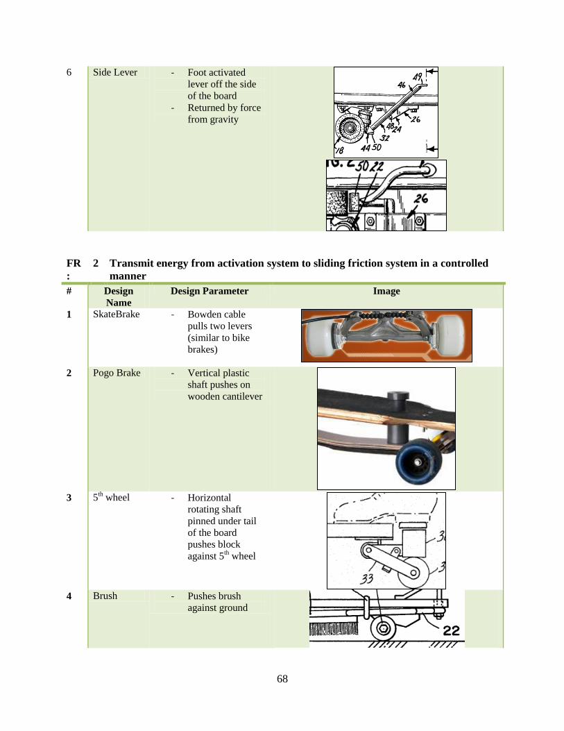
68
6 Side Lever - Foot activated
lever off the side
of the board
- Returned by force
from gravity
FR
:
2 Transmit energy from activation system to sliding friction system in a controlled
manner
# Design
Name
Design Parameter Image
1 SkateBrake - Bowden cable
pulls two levers
(similar to bike
brakes)
2 Pogo Brake - Vertical plastic
shaft pushes on
wooden cantilever
3 5
th wheel - Horizontal
rotating shaft
pinned under tail
of the board
pushes block
against 5th wheel
4 Brush - Pushes brush
against ground

69
5 Drum Brake - Vertical metal
shaft attached to
brake pad
6 Side Lever - Metal lever pivots
on rotating pin
- Attached to brake
pad at the opposite
end of the pedal
FR
:
3 Provide friction interface with a controlled normal force
# Design
Name
Design Parameter Image
1 SkateBrake - The two levers
press disc brake
pads against inside
of wheels
2 Pogo Brake - Wooden
Cantilever presses
friction pad
surface against
ground
3 5
th wheel - Horizontal
rotating shaft
pushes 5th wheel
to ground, then the
block presses
against the wheel

70
4 Brush -
5 Drum Brake - Vertical shaft
pushes brake pad
against drum
surface
6 Side Lever - Lever pushes
brake pads against
the front surface
of the rear wheels
FR
:
4 Transfer Frictional Load to the Board (Attachment)
# Design
Name
Design Parameter Image
1 SkateBrake - Frictional load
transferred
through the
wheels, which are
pinned to the
trucks 2 Pogo Brake - Frictional load
transferred
through wooden
shaft to bolted
plate under the
deck
- Attached with
bolts to deck

71
3 5th wheel - Frictional load
transferred to
bolted plate on
deck
4 Brush - Shaft with brush
on it is attached to
a ball joint that is
bolted to the deck
5 Drum Brake - Frictional load
transferred
through the
wheels, which are
pinned to the
trucks
6 Side Lever - Frictional load
transferred
through the
wheels, which are
pinned to the
trucks
FR
:
5 Return braking system to original position
# Design
Name
Design Parameter Image
1 SkateBrake - Spring in the hand
lever applies a
compressive force
to the Bowden
cable

72
2 Pogo Brake - Wooden
Cantilever acts as
a spring
3 5
th wheel - Vertically
mounted spring
attached to shaft
pushes shaft back
to initial position
4 Brush - Elastic band
attached to the
deck pulls the
shaft back up
5 Drum Brake - Metal plate
attached to deck
and shaft acts as a
cantilever spring
6 Side Lever - Larger moment on
the front end of
the lever causes
return initial
position

73
Appendix B – Acclaro File screenshot with all FRs and DPs

74

75
APPENDIX C – Iterations of lever arm and pin holder
The reason there are so many iterations to the lever arm is because we intended to place the
activation system behind the trucks, but then we noticed we wouldn’t have enough clearance of
the ground, so the whole idea was eliminated.

76
The pin holder has many iterations because at first we didn’t think of manufacturability or cost of
materials. As we progressed through the iterations, it is obvious by the figure above that we tried
to reduce the material wasted, facilitate the manufacturability and reduce stress concentrations.

77
APPENDIX D - Liquid Urethane material properties

78
APPENDIX E – Aluminum 6061 T6 material properties
Property
Name
Value Units Value
Type
Elastic
modulus
6.9e+010 N/m^2 Constant
Poisson's ratio 0.33 NA Constant
Shear modulus 2.6e+010 N/m^2 Constant
Mass density 2700 kg/m^3 Constant
Tensile
strength
3.1e+008 N/m^2 Constant
Yield strength 2.75e+008 N/m^2 Constant
Thermal
expansion
coefficient
2.4e-005 /Kelvin Constant
Thermal
conductivity
166.9 W/(m.K) Constant
Specific heat 896 J/(kg.K) Constant
Hardening
factor (0.0-1.0;
0.0=isotropic;
1.0=kinematic)
0.85 NA Constant

79
APPENDIX F – Low Carbon Steel

80
APPENDIX G – Zinc Plated Steel
Same properties Low Carbon steel but with a coat of zinc to prevent corrosion

81
APPENDIX H – Calculations
static y forces
clearance during turning
.21187
spring constant (lbs/in
mlever .66lb 0.299kg
mactivation .21187kglcm 3.38in 0.086m
llever 5.22in 0.133mmlever mactivation 0.511kg
Fspring
mlever g lcm
llever
mactivation g 3.98N
cwheel 1.23in
wboard 8in
turn atancwheel
wboard .5
turn 17.093deg
wpad 2in
cpad tan turn wpad .5 0.308in
thpad .5in
kspring 7.81lbf
in
clearance ground 1in thpad 0.5in
v .52 5 5 preloadFspring
kspring
0.115in