brake master (yl rebuild - gavilan...
TRANSCRIPT
(Concluded from precedingpage)
the internal workings of a magneto with burned grease, bronze bearing material, and electrode contaminants.
Hold the distributor block up to the light and look closely at the electrode area for signs of carbon arcing and material degradation. Sunlight works best for this check and will easily show the "rainbow" look of distributor crossfire or arcing between electrodes.
You need to see that before going through any cleaning process. If you have one of the old, black-colored distributor blocks, take it outside and throw it as far away as possible. Do everyone a favor and replace that old-style block with the new brown polyester block. It's money well spent.
OccaSionally, we still see the midgeneration, green distributor block. This should also be tossed due to some problems with failing distributor gear bushings. It isn't often, however, that you see these blocks installed in even the oldest of magnetos.
Look closely at the both sides of the distributor block for cracking that occurs around the pressed-in bearing. Some of this cracking is okay and is common to the old, black distributor block. The newer, brown block does not seem to crack as often, but is still susceptible to the problem.
Make sure you pay close attention to the block. In all magnetos, regardless of make or model, if distributor crossfire occurs you can plan on making major engine repairs. This is the only area of a magneto, aside from impulse coupling problems, that has a potential to destroy the engine by firing a cylinder out of sequence.
This magneto can quit, it can cough, sputter, backfire and spit, but if the block cross-fires (arcing between two adjacent electrodes) and does so at a high power setting (like climb power), the misfired piston will be destroyed in short order.
When in doubt, spend your money on a new block. Also, check for cracking, electrode erosion, plug tower degradation or any other reason for replacement.
Next month, we'll finish our inspection and reassemble this beastie. Then comes the part many find most difficult-timing the thing to the engine. Don't despair! It's not that hard, and all will be revealed next month.
www.lightplane-maintenance.com
Shop Work Basics
Brake Master (yl Rebuild The brake master cylinder can last for many troublejree hours with minimal care. Here's how to do it.
BY MIKE BERRY, IA
Last issue's article on brake bleeding generated additional questions on the master cylinder itself, so we added this expanded article on the master cylinder, plus some additional tips on bleeding the system once the master cylinder is rebuilt. Extra tips are included for Pipers.
The call came at 2 AM. The pilot of a Boeing 737 mashed down on the brakes a little too hard and the aircraft was stuck solid to the cool Montana ramp. The
heat generated by the melted brake discs wasn't enough to blow the tire but the ground crew gave the dull-red glow on each main wheel a wide berth.
Unable to taxi from the gate, the captain requested maintenance assistance in freeing the brake packs. He didn't consider the enormous mechanical advantage found between the master cylinders and the main-wheel brake assemblies. He also failed to comprehend the magnitude of the problem.
It is said that the secret of patience is in doing something else in the meanwhile. The maintenance crew decided to have coffee while the brakes cooled off on their own. The captain decided to "break 'em loose" by using whatever power setting was required to effect the desired result.
In the end, the "result" was predictable; a spare airplane was flown in from San Francisco, resulting in missed connections for about 48 passengers, and a written reprimand to the captain for leaving 150 feet of Goodyear rubber on the tarmac. It's amazing how much ruin can be generated by that little cylinder attached to the end of your toe.
DESCRIPTION AND TYPES The brake system master cylinder is a simple device that pumps
fluid under pressure in one direction while relieving pressure and filling the cylinder in the other. Its purpose, of course, is to push the brake caliper puck against a brake pad, which, in turn, pushes against the brake disc. Each main wheel brake has its own master cylinder for individual brake selection and the degree of braking can be varied depending on runway conditions.
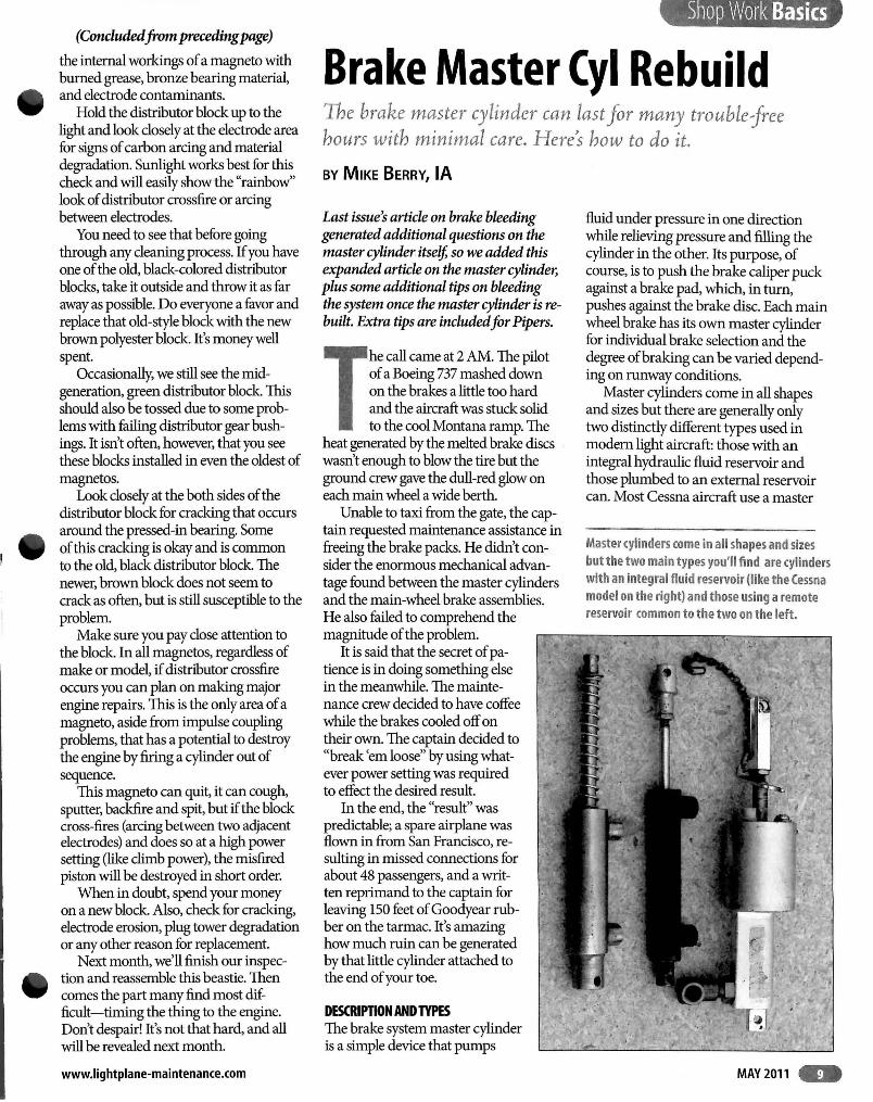
Master cylinders come in all shapes and sizes but there are generally only two distinctly different types used in modem light aircraft: those with an integral hydraulic fluid reservoir and those plumbed to an external reservoir can. Most Cessna aircraft use a master
Master cylinders come in all shapes and sizes but the two main types you'll find are cylinders with an integral fluid reservoir (like the Cessna model on the right) and those using a remote reservoir (ommon to the two on the left.
MAY2011 ..

Screwing the inner housing out of the reservoir body will allow for O-ring and packing replacement. Be sure the reservoir is clean and free of all dirt.
cylinder with an attached reservoir bowl. A plastic plug is screwed into the top of the cylinder, and filling the reservoir is accomplished by using a squirt can of 5606 (H being the latest version), a long hose, and the Braille method of aircraft servicing.
Piper and Beechcraft, among others, generally use a master cylinder with an external hydraulic reservoir. The
The inner workings of the Cessna master cylinder can be accessed by removing the set screw and turning the inner housing out of the reservoir body.
.. MAY 2011
real advantage in this design is in the servicing of the system. It seems every Cessna made has a fluid-soaked section of carpet around the left rudder pedals while most all other airplanes stay reasonably clean in that area.
LOCK-O-SEALS Master cylinder operation is Simple. Pushing the piston
into the cylinder closes a spring-loaded fill valve and pressurizes the fluid in the cylinder. The resulting pressure and flow is transmitted to the brake wheel caliper, which moves the brake puck against the disc.
When the piston is allowed to retract, the spring-loaded fill valve opens, allowing reservoir fluid to enter the cylinder. The cylinder will only fill with enough hydraulic fluid to make up for any loss in moving the pucks in the caliper-very little circulation of fluid ever takes place in normal service.
Regardless of the style, the master cylinder is comprised of a single piston and a few O-rings. The body is equipped with fittings and a series oflinkages for dual pedal operation and the installation allows for pivoting on both ends. The
most complex part of the system is the fill valve and its operation. It operation is also the most problematic.
The spring-loaded fill valve is nothing more than an O-ring seal attached to a floating washer or spacer that moves against spring pressure, sealing the reservoir supply from the pressure side of the cylinder. There are several names for the assembly but in a generic way this fill valve is called a Lock-O-Seal.
The name is derived from Cessna's version of the seal that is a flat steel washer into which has been fitted an O-ring. This one-piece pack is then installed on the shaft and is located against the piston. The same kind of arrangement is made for other styles of master cylinders as well.
As the piston is moved up and down, the Lock-O-Seal alternately
seals and then opens with each movement of the piston. If the seal is cut, ripped, chaffed, or just plain worn out, the brake will feel mushy, and braking action will be greatly diminished.
PROBLEM IDENTIFICATION The degree to which the Lock-O-Seal leaks will determine the failure mode for the cylinder. A slow leak will prOvide a spongy pedal feel. If the seal is cut or missing, there will be no pedal action at all. In all cases, master cylinder failure can be separated from other brake system problems by recognizing whether or not fluid movement can be felt in the pedals.
Brake systems that have trapped air in the calipers or lines can feel soft but it's possible to still feel fluid movement through the master cylinder. In cases like this, pumping the brakes will eventually provide a stiff (relatively) pedal once all the air in the lines has been compressed as much as pOSSible.
Failures in the master cylinder, though, can be identified by the flat feel of the pedal. There will be little if any resistance to piston movement and the only thing felt in the pedals will be the return-spring action. Generally speaking, when the fill-valve fails (assuming the system is full of fluid), the pedal will go all the way to the floor without providing even a hint of any braking action.
At this point, master cylinder rebuild will be required. Fortunately, the job is easy and requires no special tools or equipment. It does require A&P supervision for certified aircraft, however.
REMOVAl AND RESEAL The most difficult part of rebuilding the master cylinder is gaining access to the component. Stuck behind the rudder pedals, the master cylinders are usually mounted to structures underneath the floorboards or intertwined in an array of tubes and linkages.
Piper cylinders are the easiest to remove but you pay for the convenience in another way. Bleeding the brake system on many Piper aircraft can be an exercise in pure frustration. More about that later.
For most installations, you'll need a Phillips screwdriver, a set of open-ended wrenches, a cotter pin puller, a good set of Allen wrenches, and some #4 plugs to cap the hydraulic lines after they're
LIGHT PLANE MAINTENANCE

removed from the cylinder. It would also be helpful to have a good flashlight and several shop rags at hand.
.A Removing the master cylinder reW' quires no special instructions; however, it
will require that your body yield to some contortions usually seen at the circus. To make matters worse, you'll need to do this while holding on to various tools and supplies.
If you're patient, the job will go smoothly, but even then it can draw out some behaviors you may have thought were only the afflictions of youth. Like what happened when your neighbor's dog left a gift for you in your yard.
It would be advisable to look closely at how the master cylinder is attached to the brake linkages. Take a photo, make a drawing or have a diagram handy.
Note the position of any washers, spacers, and overlapping link arms and rod ends. Also, be sure to loosen the brake lines before removing the master cylinder mounting hardware. Then cap all lines and fittings.
Once removed, the cylinder can be disassembled and cleaned. On Cessna
_ master cylinders, remove the setscrew ,., located along the side of the cylinder
toward the top. 'Then unscrew the cover. When loose, the cover will pull out of the body, taking the rod, piston, and Locka-Seal assembly as a complete unit. On Piper and Beech aircraft, remove the snap ring located in the clevis end of the cylinder and pull the rod and piston assemblyout.
Check the fill-valve seal (or Lock-OSeal) for condition and make sure nothing is lying in the bottom of the master cylinder body. Remove all a-ring seals and packings and lay them off to the side. The Lock-a-Seal, regardless of make, is held to the rod with a nut, washer, and spring.
Note the position of these parts before disassembly and draw a picture of the fit, if necessary. Clean all parts in solvent and air dry. Check for scoring on the cylinder walls and make certain any nicks or gouges are removed from the piston rod.
Also, check any gland nuts or inserts .. for wear. The piston rod will move in and ., out of the cylinder end while it rides on
an internal O-ring seal. Often, the rod is subjected to a side load that wears away at the aluminum gland nut. Check for any
www.lightplane-maintenance.com
excessive wear in this area. It will be helpful to leave the clevis pin attached to the piston rod so rudder pedal rigging will remain unchanged.
00 NOT DAMAGE LOCK-O-SEAL
ASSEMBLY AND INSTALlATION All seals, gaskets, and packings should be replaced with new. Parts are readily available and can be ordered from your local shop. The most expensive item will be the Lock-a-Seal but when totaled, you'll likely spend under $20 for all the parts you need.
Replacing a-rings and seals is no problem, but the Lock-a-Seal needs to be properly adjusted in order to provide the check-valve action required to fill the cylinder. After confirming that all the parts are installed in their proper locations' adjust the nut and spring-loaded piston so that there is no clearance between the piston and the Lock-a-Seal.
Then back off on the nut to allow for a 0.040-inch measured clearance between the piston and the seal. Other brands of master cylinders may be adjusted in a similar fashion but remember that if the clearance is too large or too small, you'll need to pump the brakes to get the desired result.
a-rings should be bathed in clean 5606H hydraulic fluid prior to assembly. Be sure to remove any dirt or debris from the master cylinder reservoir or pressure chamber. 'The old 5606G and new 5606H fluids are compatible (except natural rubber a-rings may not be OK with H).
Reinstalling the master cylinder is accomplished by reversing the removal process. Make sure to cotter pin any castle nuts and clevis pins and ensure that there is no binding or catching of the linkages during full application of the rudder pedals. The cylinder needs to float freely through all pedal ranges without interference.
Connect the hydraulic lines but do not tighten the "B" nuts. 'They'll need to be loose during the bleeding procedure .
REMOVING THE AIR There are as many opinions about brake bleeding as there are about engine
Most master cylinders have some form of a lock-O-Seal fill valve. Typically, a spring-loaded piston will move against the seal, closing off the reservoir from the pressure side of the cylinder until the brake is released. The piston then moves away from the seal and fluid is allowed to fill the chamber.
break-in procedures. Some methods are simple and straightforward while others are wrought with complex maneuvers and multiple functions. All of them will accomplish the same thing with the only variable being the time it takes to complete the job.
Of the various makes and models of brake and master cylinder configurations, the Cessna system is the easiest to bleed. Piper aircraft, on the other hand, have four vertically mounted master cylinders with a fifth parking brake cylinder fixed to the panel. 'This system is difficult to bleed in the conventional manner and requires some special considerations during the procedure. For all aircraft other than the Piper brand, a bottom-totop bleeding procedure will work well.
Once the master cylinders are reinstalled, attach a clear hose to the end of a hand-held squirt can full of Mil Spec 5606 hydraulic fluid, loosen the brake bleeder screw on the wheel brake caliper, and slide the clear hose over the screw.
Be sure to pump out any air trapped in the clear hose before attaching the line to the brake screw. 'Then, loosen the fittings on the brake lines attached to the master cylinder and remove the filler plug from the top of the cylinder. While your assistant pumps the fluid up to the master cylinder, you will need to monitor what air and oil seeps from the loose fittings .
Keep plenty of rags available to soak up the draining fluid. When it looks like only clear fluid is leaking from the lines,
MAY2011 ..
1Sl-_--10
NOTE
,)1 ,A
I
I I I
12
11
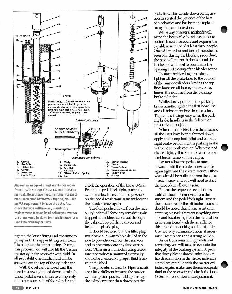
Filler plug (17) must be vented so pressure cannot build up in the reservoir during brake operation. Remove plug and dr1ll 1/16" hole, 30 0 from vertical, If plug Is not vented.
o. 040 ±O. 005 INCH
ASSEMBLY OF PISTON -1. Clevis 7. Body 13. Piston Spring 2. Jamb Nut 8. Reservoir 14. Piston 3. Piston Rod 9. O-Ring 15. Lock-O-Seal 4. Cover 10. Cylinder 16. Compensating Sleeve 5. Setscrew 11. Piston Return Spring _ 17. Filler Plug ; 6. Cover Boss 18. Screw 12. Nut
Above is an image of a master cylinder repair from a 19705 vintage Cessna 182 maintenance manual. Always have the current maintenance manual on hand before tackling the job-it's an FAA requirement to have the data. Also, check that you will have any mandatory replacement parts on hand before you start or the plane (ould be down for maintenance for a long time waiting for parts.
tighten the lower fitting and continue to pump until the upper fitting runs clear. Then tighten the upper fitting. During this process, you will also fill the Cessna master cylinder reservoir with fluid. In all probability, hydraulic fluid will be spewing out the top of the cylinder, too.
With the oil can removed and the bleeder screw tightened down, stroke the brake pedal several times to completely fill the pressure side of the cylinder and
.. MAY 2011
check the operation of the Lock-a-Seal. Even if the pedal feels tight, pump the cylinder a few times and hold pressure on the pedal while your assistant loosens the bleeder screw again.
The fluid pushed down from the master cylinder will force any remaining air trapped at the bleed screw out through the caliper. Top off the reservoir and install the plastic plug.
It should be noted that the filler plug must have a 1I16-inch hole drilled in the side to provide a vent for the reservoir and to accommodate any fluid expansion. Other aircraft models using a separate reservoir can mounted externally should be checked for proper fluid levels when finished.
The procedures used for Piper aircraft are a little different because the master cylinder piston pushes fluid up through the cylinder rather than down into the
brake line. This upside-down configuration has tested the patience of the best of mechanics and has been the topic of many hangar discussions.
While any of several methods will work, the best we've found uses a top-tobottom bleed procedure and requires the capable assistance of at least three people. One will monitor and top off the external reservoir during the bleeding procedure, the next will pump the brakes, and the last helper will need to coordinate the opening and closing of the bleeder screw.
To start the bleeding procedure, tighten all the brake lines to the bottom of the master cylinders, leaving the top lines loose on all four cylinders. Also, loosen the exit line from the parkingbrake cylinder.
While slowly pumping the parking brake handle, tighten the first loose line and all subsequent lines in succession. Tighten the fittings only when the parking brake handle is in the full out (or pressurized) position.
When all air is bled from the lines and all the lines have been tightened down, apply and pump both pilot and co-pilot right brake pedals and the parking brake with one smooth motion. When the pedals feel tight, yell to your assistant to open the bleeder screw on the caliper.
Do not allow the pedals to move upward until the bleeder screw is once again tight and the system secure. Otherwise, air will be pulled in from the loose bleeder screw and you will need to start the procedure all over again.
Repeat the sequence several times until all the air is removed from the system and the pedal feels tight. Repeat the procedure for the left brake pedals. It should be noted that if your assistant is entering his twilight years (anything over 40), and is suffering from the natural loss in hearing found with the so afflicted, this procedure could go on indefinitely. Use two-way communications, if necessary. Two tin cans and a string will do.
Aside from reinstalling panels and carpeting, you will need to evaluate the integrity of the brakirlg system. A pedal that slowly bleeds down under load or has dead motion in the stroke indicates a problem remains with the master cylinder. Again, make sure there's adequate fluid in the reservoir and check the Locka-Seal for condition and adjustment.
LIGHT PLANE MAINTENANCE