bowthorpe emp lv/mv outdoor surge arresters · all our arrester production facilities have...
TRANSCRIPT

Bowthorpe EMP LV/MV Outdoor Surge Arresters
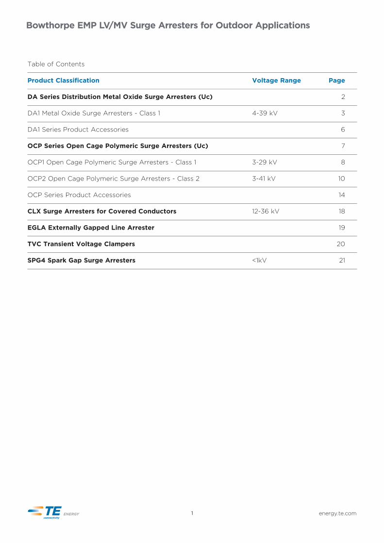
Table of Contents
Product Classification Voltage Range Page
DA Series Distribution Metal Oxide Surge Arresters (Uc) 2
DA1 Metal Oxide Surge Arresters - Class 1 4-39 kV 3
DA1 Series Product Accessories 6
OCP Series Open Cage Polymeric Surge Arresters (Uc) 7
OCP1 Open Cage Polymeric Surge Arresters - Class 1 3-29 kV 8
OCP2 Open Cage Polymeric Surge Arresters - Class 2 3-41 kV 10
OCP Series Product Accessories 14
CLX Surge Arresters for Covered Conductors 12-36 kV 18
EGLA Externally Gapped Line Arrester 19
TVC Transient Voltage Clampers 20
SPG4 Spark Gap Surge Arresters <1kV 21
Bowthorpe EMP LV/MV Surge Arresters for Outdoor Applications
energy.te.com1

energy.te.com 2
TE Connectivity Bowthorpe EMP LV/MV Outdoor Surge Arresters
Bowthorpe EMP pioneered the development of polymeric composite housed surge arresters in the early 1980’s and since then has a proven service experience across the globe, operating in the worlds toughest environments.
Bowthorpe EMP surge arresters provide active over voltage protection that contributes directly to improved reliability of your system, reducing lost minutes and protecting expensive assets.
Bowthorpe EMP DA silicone surge arresters have been designed and tested to meet our customers demands with reliability and offering improved operational performance. The DA development was based on more than 40 years of experience in arrester design and manufacture within TE Energy.
The DA series is tested and qualified as per IEC 60099-4 standards and all test reports are independently certified. 1) Proven moisture sealing technology2) Non-tracking insulating silicone
materials. 3) Fully integrated, single piece and
void-less design. 4) Reliable earth lead disconnect5) Safe mode of failure6) Quality
DA Series Distribution Metal Oxide Surge Arresters
Sealing All arrester cores are encapsulated in silicone insulating housing. A per-manent chemical bond connects the arrester core and the non-tracking silicone housing. This invisible inter-face prevents moisture from entering during severe thermal fluctuations due to normal climatic and energy absorption events.
Polymer housing Non-tracking and hydrophobic silicone insulating material is used for DA arrester housings. The DA surge arrester series is available with standard or extra creepage distance. The housing material has proven performance in long term TERT and UV aging tests and proven resistance to flammability.
Integrated design Manufacturing integrates all compo-nents in a single piece. There are no glued interfaces. The design is void and gap free ensuring peak perfor-mance under the harshest conditions.
Reliable and consistent ELDOur robust earth lead disconnect, (ELD) offers operational reliability and consistency. It was designed to operate in event of arrester failure, removing earth connection and fault from line. It can be shipped and stored restriction free.
Safe mode of failure Our high energy arresters are tested in accordance with the pre-failing mode of failure test in IEC 60099-4. This testing has proven the DA1 surge arrester series safe and predictable failure characteristics.
Quality The DA series arrester is manufactured to international quality standards in TE Connectivity production facilities. We perform 100% routine testing on arresters:1) Visual inspection2) Reference voltage test3) Partial discharge test

TE Connectivity Bowthorpe EMP LV/MV Outdoor Surge Arresters
energy.te.com3
Qualification testingDecades of insulating materials, arrester design and development experience has been combined to create the DA series arrester. The basic construction comprises of high energy ZnO varistors, assembled within a flame retardant composite laminate tube. The following design IEC 60099-4 design type tests have been carried out on the DA series arresters:
1) Insulation withstand tests on the arrester housing2) Residual voltage tests3) Long-duration current impulse withstand test4) Operating duty tests5) Short-circuit tests6) Internal partial discharge tests7) Test of the bending moment8) Weather Ageing Test9) Power –frequency voltage versus time characteristics
on an arrester
The silicone insulating material has been designed and optimised for arrester application. The following additional testing was performed in the qualification of the silicone: 1) Tracking and Erosion2) UV testing3) Thermal endurance4) Dielectric testing5) Flammability testing.6) Long term water immersion testing
Production and quality All our arrester production facilities have implemented QC and QA procedures according to international standards to ensure test programs that guarantee quality conforming products. 100% of all Varistors are tested and stamped with unique varistor residual and reference voltage. The following tests are performed on varistors:
1) Residual voltage2) Reference voltage3) Leakage current4) Physical examination to screen damaged varistors5) LOT test: High current impulse test6) LOT test: Aging test
At the end of the arrester assembly process, the following mandatory IEC tests are completed on every arrester: - Visual inspection - Reference voltage test - PD testing.
Birdcap
Corrosion resistantaluminium fittings
Silicone rubber housing Mould in Place
ZnO varistors
Flame retardantglass filled epoxy laminate
DA1 Metal Oxide Surge Arresters - Class 1
Bracket ELD
Earth clamp
TE Connectivity Bowthorpe EMP LV/MV Outdoor Surge Arresters
energy.te.com 4
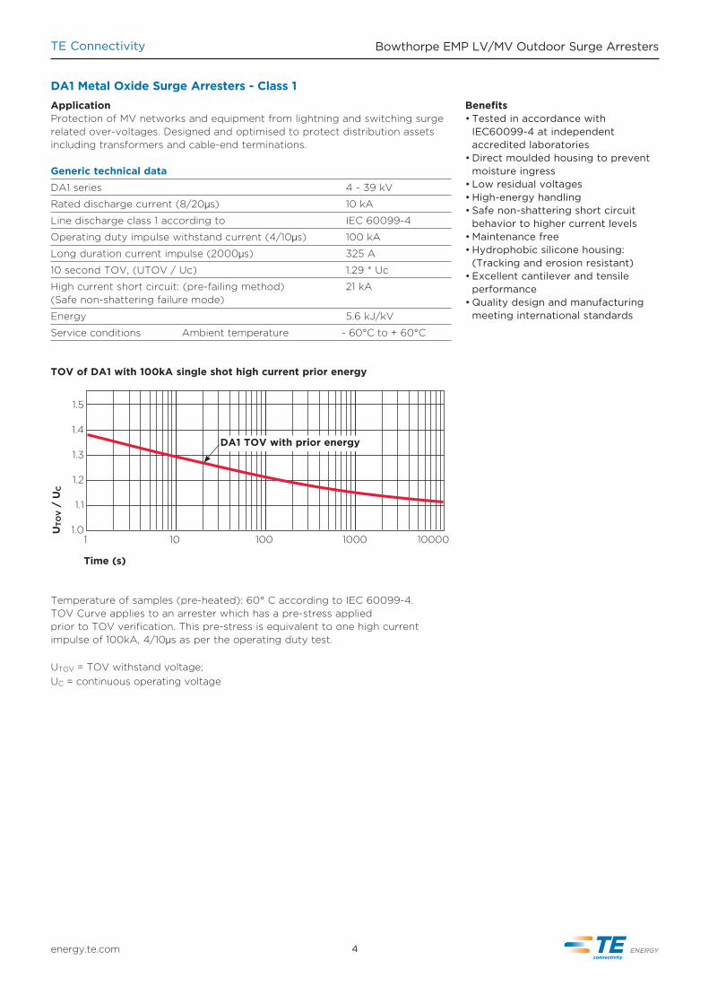
DA1 Metal Oxide Surge Arresters - Class 1ApplicationProtection of MV networks and equipment from lightning and switching surgerelated over-voltages. Designed and optimised to protect distribution assets including transformers and cable-end terminations.
Generic technical dataDA1 series 4 - 39 kV
Rated discharge current (8/20µs) 10 kA
Line discharge class 1 according to IEC 60099-4
Operating duty impulse withstand current (4/10µs) 100 kA
Long duration current impulse (2000µs) 325 A
10 second TOV, (UTOV / Uc) 1.29 * Uc
High current short circuit: (pre-failing method) 21 kA(Safe non-shattering failure mode)
Energy 5.6 kJ/kV
Service conditions Ambient temperature - 60°C to + 60°C
Benefits • Tested in accordance with
IEC60099-4 at independent accredited laboratories
• Direct moulded housing to prevent moisture ingress
• Low residual voltages• High-energy handling• Safe non-shattering short circuit
behavior to higher current levels• Maintenance free• Hydrophobic silicone housing:
(Tracking and erosion resistant)• Excellent cantilever and tensile
performance• Quality design and manufacturing
meeting international standards
Temperature of samples (pre-heated): 60° C according to IEC 60099-4. TOV Curve applies to an arrester which has a pre-stress appliedprior to TOV verification. This pre-stress is equivalent to one high currentimpulse of 100kA, 4/10µs as per the operating duty test.
UTOV = TOV withstand voltage;UC = continuous operating voltage
1.5
1.4
1.3
1.2
1.1
1.0
Time (s)
1 10000100010010
UTO
V /
UC
DA1 TOV with prior energy
TOV of DA1 with 100kA single shot high current prior energy
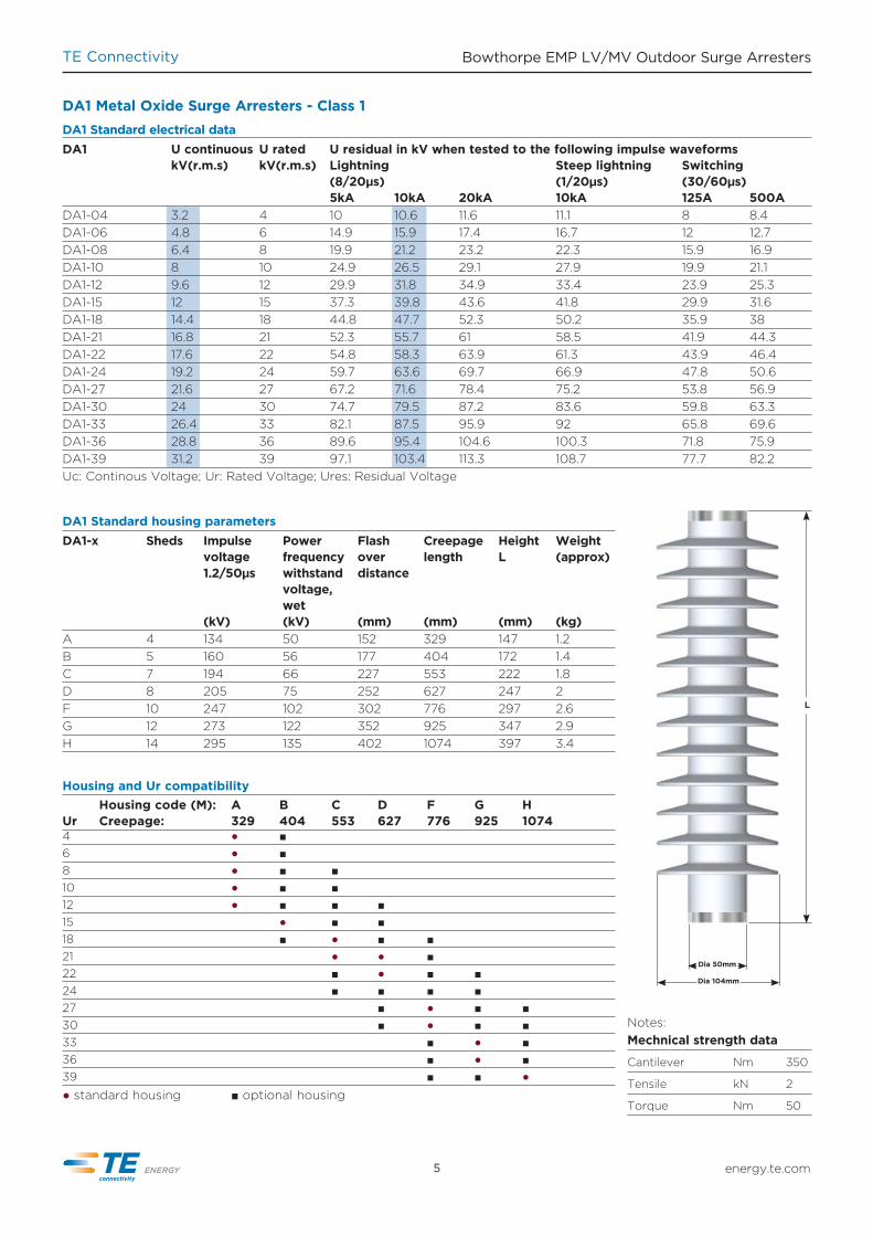
DA1 Standard electrical dataDA1 U continuous U rated U residual in kV when tested to the following impulse waveforms kV(r.m.s) kV(r.m.s) Lightning Steep lightning Switching (8/20µs) (1/20µs) (30/60µs) 5kA 10kA 20kA 10kA 125A 500ADA1-04 3.2 4 10 10.6 11.6 11.1 8 8.4DA1-06 4.8 6 14.9 15.9 17.4 16.7 12 12.7DA1-08 6.4 8 19.9 21.2 23.2 22.3 15.9 16.9DA1-10 8 10 24.9 26.5 29.1 27.9 19.9 21.1DA1-12 9.6 12 29.9 31.8 34.9 33.4 23.9 25.3DA1-15 12 15 37.3 39.8 43.6 41.8 29.9 31.6DA1-18 14.4 18 44.8 47.7 52.3 50.2 35.9 38DA1-21 16.8 21 52.3 55.7 61 58.5 41.9 44.3DA1-22 17.6 22 54.8 58.3 63.9 61.3 43.9 46.4DA1-24 19.2 24 59.7 63.6 69.7 66.9 47.8 50.6DA1-27 21.6 27 67.2 71.6 78.4 75.2 53.8 56.9DA1-30 24 30 74.7 79.5 87.2 83.6 59.8 63.3DA1-33 26.4 33 82.1 87.5 95.9 92 65.8 69.6DA1-36 28.8 36 89.6 95.4 104.6 100.3 71.8 75.9DA1-39 31.2 39 97.1 103.4 113.3 108.7 77.7 82.2Uc: Continous Voltage; Ur: Rated Voltage; Ures: Residual Voltage
TE Connectivity Bowthorpe EMP LV/MV Outdoor Surge Arresters
energy.te.com5
DA1 Metal Oxide Surge Arresters - Class 1
Housing code (M): A B C D F G H Ur Creepage: 329 404 553 627 776 925 10744 ● ■ 6 ● ■ 8 ● ■ ■ 10 ● ■ ■ 12 ● ■ ■ ■ 15 ● ■ ■ 18 ■ ● ■ ■ 21 ● ● ■ 22 ■ ● ■ ■ 24 ■ ■ ■ ■ 27 ■ ● ■ ■30 ■ ● ■ ■33 ■ ● ■36 ■ ● ■39 ■ ■ ●● standard housing ■ optional housing
Housing and Ur compatibility
L
Dia 50mm
Dia 104mm
Notes: Mechnical strength data
Cantilever Nm 350
Tensile kN 2
Torque Nm 50
DA1 Standard housing parametersDA1-x Sheds Impulse Power Flash Creepage Height Weight voltage frequency over length L (approx) 1.2/50µs withstand distance voltage, wet (kV) (kV) (mm) (mm) (mm) (kg)A 4 134 50 152 329 147 1.2B 5 160 56 177 404 172 1.4C 7 194 66 227 553 222 1.8D 8 205 75 252 627 247 2F 10 247 102 302 776 297 2.6G 12 273 122 352 925 347 2.9H 14 295 135 402 1074 397 3.4

TE Connectivity Bowthorpe EMP LV/MV Outdoor Surge Arresters
energy.te.com 6
DA1 Product Accessories - Class 1
Line lead accessories
Y Y M - 1 2 3 4 5 6 - P Naming convention cross reference: DA1 = series type: DA1 for 10kA, class1 arrester. YY = Ur see page 5 M = housing code see page 5
B xxxxx Birdcap with F accessory
H xxxxx M12 Cap screw & spring washer
M xxxxx Exposed stud for line lead connection
O xxxxx No stud. No accessories
1
E xxxxx Birdcap with M accessory
F xxxxx Exposed stud for lug connection
xx H xxx M12 Cap screw & spring washer
xx M xxxExposed stud for line lead connection
xx O xxxNo stud. No accessories
Earth lead accessories:
xx D xxx Disconnect + M accessory
xx E xxx Disconnect + F accessory
xx F xxx Exposed stud for lug connection
3
Mounting bracket options:
xxxxx 0 No option
xxxxx 1 NEMA Cross arm bracket
6
O M H F B P xxxxx S-Clamp
Q xxxxx L-Clamp
Packaging I Individual Packing (1 arrester per carton) S 3 Pack (3 arresters per carton)
P
Ordering example: BOW-DA1-12A-F0E0B0-IAll fastners M12 unless stated
BOW-DA1-
E
Mounting brackets:
xxxx A x Straight 2 hole mounting bracket*
xxxx B x Insulating bracket*
xxxx C xDIN metal bracket, (stainless)*
xxxx E xDIN metal bracket, (galvanised)*
xxxx N x No mounting accessories
5
*only available in –I packaging option
Line lead optionsx 0 xxxx No Line Lead Wirex 1 xxxx 0.5m 16mm2 Copper Line Lead & one M12 lugx 2 xxxx 1m 16mm2 Copper Line Lead & one M12 lugx 3 xxxx 1m 16mm2 Copper Line Lead & no lug
x 4 xxxx 0.5m 35mm2 Copper Line Lead & one M12 lugx 5 xxxx 1m 35mm2 Copper Line Lead & one M12 lugx 6 xxxx 1m 35mm2 Copper Line Lead & no lug
2
For addition lead options, please contact support team at:[email protected]
Earth lead optionsxxx 0 xx No Earth Lead Wirexxx 1 xx 0.5m 16mm2 Copper Earth Lead & one M12 lugxxx 2 xx 1m 16mm2 Copper Earth Lead & one M12 lugxxx 3 xx 1m 16mm2 Copper Earth Lead & no lug
4xxx 4 xx 0.5m 35mm2 Copper Earth Lead & one M12 lugxxx 5 xx 1m 35mm2 Copper Earth Lead & one M12 lugxxx 6 xx 1m 35mm2 Copper Earth Lead & no lug
For addition lead options, please contact support team at:[email protected]

TE Connectivity Bowthorpe EMP LV/MV Outdoor Surge Arresters
OCP series constructionAt the core of the Bowthorpe EMP OCP design is our improved ZnO varistor disk, which has superior ther-mal and electrical characteristics and stability. The resulting new varistor and OCP design combination has resulted in superior energy handling and TOV performance. This superior thermal behavior yields products with:
• Excellent TOV performance.• Safe, non-shattering failure in the
short circuit test by pre-failing to higher fault currents.
• High energy handling capability.
The crimped structural construction ensures light weight product with optimal mechanical strength. The manufacturing process ensures void free construction and optimum interface sealing. This is achieved by bonding the silicone housing directly to the ZnO discs and aluminium fittings using a TE Connectivity proprietary bonding solution.
OCP silicone hydrophobic features• Alternating sheds for superior
pollution flash over resistance• Superior TERT performance• Housing tested to IEC 1000hr
salt fog test• Constant voltage: 4.5kV, >360min Step voltage: >300min - All eventual failures by erosion
only, ie no tracking in voltage test
Excellent hydrophobicity Safe short circuit failure Superior TERT performance
1
2
3
4
Bowthorpe EMP pioneered the development of polymeric housed surge arresters in the early 1980’s and has a proven service experience across the globe, operating in the worlds toughest environments.
Bowthorpe EMP “OCP” silicone surge arresters have been designed and tested to meet customers toughest environmental conditions and to meet the requirements of IEC60099-4.
Benefits• Tested in accordance with
IEC60099-4 at independent accredited laboratories
• Superior protection margins• Direct molded housing to prevent
moisture ingress• Low residual voltages• High-energy handling• Superior TOV performance• Safe non-shattering short circuit
behavior to higher current levels• Maintenance free• Hydrophobic silicone housing:
(Tracking and erosion resistant)• Excellent cantilever and tensile
performance• Excellent mechanical, vibration and
impact withstand capability• Quality design and manu facturing,
ISO 9001 and 14001 compliant
OCP Series Open Cage Polymeric Surge Arresters
The construction of the OCP design comprises of:1 ZnO, (Zinc Oxide) varistors2 TE Connectivity proprietary silicone
housing3 Flame retardant FRP structure4 Corrosion resistant aluminium
fittings
energy.te.com7

TE Connectivity Bowthorpe EMP LV/MV Outdoor Surge Arresters
energy.te.com 8
Application Protection of MV networks and equipment from lightning and switching surge related over-voltages in areas with relatively high iso-keraunic levels. Suitablefor both outdoor and indoor use to protect transformers and cable end terminations.
Generic technical dataOCP1 S/L Series 3-29kV Uc
Rated discharge current (8/20µs) 10kA
Line discharge class 1 according to IEC 60099-4
Operating duty impulse withstand current (4/10µs) 100kA
Long duration current impulse (2000µs) 350A
High current short circuit: (pre-failing method) 25kA(Safe non-shattering failure mode)
Energy 2 Long duration impulses 4.1kJ/kVUc
Service conditions Ambient temperature - 60°C to + 60°C
OCP1 Open Cage Polymeric Surge Arresters - Class 1
1.5
1.4
1.3
1.2
1.1
1.0
Time (s)
1 10000100010010
UTO
V /
UC
Temporary overvoltage (TOV) of OCP1 with prior energy
TOV Curve
Temperature of samples (pre-heated): 60° C according to IEC 60099-4. TOV Curve applies to an arrester which has a pre-stress appliedprior to TOV verification. This pre-stress is equivalent to one high currentimpulse of 100kA, 4/10µs as per the operating duty test.
UTOV = TOV withstand voltage;UC = continuous operating voltage
Birdcap
Corrosion resistantaluminium fittings
Silicone rubber housing Mould in Place
ZnO varistors
Flame retardantFRP structure
Bracket ELDEarth clamp

TE Connectivity Bowthorpe EMP LV/MV Outdoor Surge Arresters
L
Dia 97mmDia 119mm
Notes: Mechnical strength data
Cantilever Nm 350
Tensile kN 2
Torque Nm 50
For accessory and ordering information, please refer to page 14
Tested in accordance with IEC 60099-4
OCP1-xxS Standard housing parametersOCP1 Sheds Impulse Power Flash Creepage Height Weight voltage frequency over length L (approx) 1.2/50µs withstand distance voltage, wet (kV) (kV) (mm) (mm) (mm) (kg)03 5 145 47 176 380 183 1.804 5 145 47 176 380 183 1.805 5 145 47 176 380 183 1.806 5 145 47 176 380 183 1.808 5 145 47 176 380 183 1.809 5 145 47 176 380 183 1.810 5 145 47 176 380 183 1.812 5 145 47 176 380 183 1.815 7 165 57 214 505 220 2.218 9 180 70 254 632 260 2.6520 9 180 70 254 632 260 2.6521 11 200 80 293 758 299 2.122 11 200 80 293 758 299 2.124 11 200 80 293 758 299 2.129 13 230 95 334 885 340 3.4
OCP1-xxL Extended housing parametersOCP1 Sheds Impulse Power Flash Creepage Height Weight voltage frequency over length L (approx) 1.2/50µs withstand distance voltage, wet (kV) (kV) (mm) (mm) (mm) (kg)03 7 165 57 214 505 220 2.204 7 165 57 214 505 220 2.205 7 165 57 214 505 220 2.206 7 165 57 214 505 220 2.208 7 165 57 214 505 220 2.209 7 165 57 214 505 220 2.210 7 165 57 214 505 220 2.212 7 165 57 214 505 220 2.215 9 180 70 254 632 260 2.6518 11 200 80 293 758 299 320 11 200 80 293 758 299 321 13 230 95 334 885 340 3.422 13 230 95 334 885 340 3.424 13 230 95 334 885 340 3.4
energy.te.com9
OCP1 Standard electrical dataOCP1 U continuous U rated U residual in kV when tested to the following impulse waveforms kV(r.m.s) kV(r.m.s) Lightning Steep lightning Switching (8/20µs) (1/20µs) (30/60µs) 5kA 10kA 20kA 10kA 125A 500A3 3 3.75 9.77 10.37 11.48 11.28 7.81 8.084 4 5 13.03 13.83 15.31 15.04 10.42 10.775 5 6.25 16.29 17.29 19.14 18.8 13.02 13.466 6 7.5 19.55 20.75 22.97 22.56 15.62 16.158 8 10 26.06 27.66 30.62 30.08 20.83 21.549 9 11.25 29.32 31.12 34.45 33.84 23.44 24.2310 10 12.5 32.58 34.58 38.28 37.6 26.04 26.9212 12 15 39.1 41.5 45.94 45.12 31.25 32.315 15 18.75 48.87 51.87 57.42 56.4 39.06 40.3818 18 22.5 58.64 62.24 68.9 67.68 46.87 48.4620 20 25 65.16 69.16 76.56 75.2 52.08 53.8421 21 26.25 68.42 72.62 80.39 78.96 54.68 56.5322 22 27.5 71.68 76.08 84.22 82.72 57.29 59.2224 24 30 78.19 82.99 91.87 90.24 62.5 64.6129 29 36.35 94.48 100.28 111 109.04 75.52 78.07Uc: Continous Voltage; Ur: Rated Voltage; Ures: Residual Voltage

TE Connectivity Bowthorpe EMP LV/MV Outdoor Surge Arresters
energy.te.com 10
ApplicationProtection of MV networks, sensitive equipment and substations from lightning and switching surge related over-voltages in areas with relatively high iso-keraunic levels.
Generic technical data
OCP2 S/L series 3-29kV Uc
Rated discharge current (8/20µs) 10kA
Line discharge class 2 according to IEC 60099-4
Operating duty impulse withstand current (4/10µs) 100kA
Long duration current impulse (2000µs) 530A
High current short circuit: (pre-failing method) 40kA(Safe non-shattering failure mode)
Energy 2 Long duration impulses 6.0kJ/kVUc
Service conditions Ambient temperature - 60°C to + 60°C
Temperature of samples (pre-heated): 60° C according to IEC 60099-4. TOV Curve applies to an arrester which has a pre-stress applied prior to TOV verification. This pre-stress is equivalent to two long duration current impulses having duration of 2000µs and total energy equal to 6.0 kJ/kV Uc.
UTOV = TOV withstand voltage;UC = continuous operating voltage
OCP2 Open Cage Polymeric Surge Arresters - Class 2
1.5
1.4
1.3
1.2
1.1
1.0
Time (s)
1 10000100010010
UTO
V /
UC
Temporary overvoltage (TOV) of OCP2 with prior energy
TOV Curve
Birdcap
Corrosion resistantaluminium fittings
Silicone rubber housing Mould in Place
ZnO varistors
Flame retardantFRP structure
Bracket ELDEarth clamp
TE Connectivity Bowthorpe EMP LV/MV Outdoor Surge Arresters
energy.te.com11
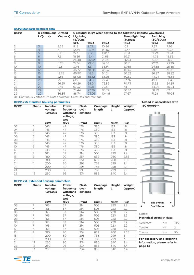
OCP2-xxS Standard housing parametersOCP2 Sheds Impulse Power Flash Creepage Height Weight voltage frequency over length L (approx) 1.2/50µs withstand distance voltage, wet (kV) (kV) (mm) (mm) (mm) (kg)03 5 145 47 176 380 183 1.804 5 145 47 176 380 183 1.805 5 145 47 176 380 183 1.806 5 145 47 176 380 183 1.808 5 145 47 176 380 183 1.809 5 145 47 176 380 183 1.810 5 145 47 176 380 183 1.812 5 145 47 176 380 183 1.815 7 165 57 214 505 220 2.218 9 180 70 254 632 260 2.6520 9 180 70 254 632 260 2.6521 11 200 80 293 758 299 2.122 11 200 80 293 758 299 2.124 11 200 80 293 758 299 2.129 13 230 95 334 885 340 3.4
OCP2-xxL Extended housing parametersOCP2 Sheds Impulse Power Flash Creepage Height Weight voltage frequency over length L (approx) 1.2/50µs withstand distance voltage, wet (kV) (kV) (mm) (mm) (mm) (kg)03 7 165 57 214 505 220 2.204 7 165 57 214 505 220 2.205 7 165 57 214 505 220 2.206 7 165 57 214 505 220 2.208 7 165 57 214 505 220 2.209 7 165 57 214 505 220 2.210 7 165 57 214 505 220 2.212 7 165 57 214 505 220 2.215 9 180 70 254 632 260 2.6518 11 200 80 293 758 299 320 11 200 80 293 758 299 321 13 230 95 334 885 340 3.422 13 230 95 334 885 340 3.424 13 230 95 334 885 340 3.4
L
Dia 97mmDia 119mm
Notes: Mechnical strength data:
Cantilever Nm 350
Tensile kN 2
Torque Nm 50
For accessory and ordering information, please refer to page 14
Tested in accordance with IEC 60099-4
OCP2 Standard electrical dataOCP2 U continuous U rated U residual in kV when tested to the following impulse waveforms kV(r.m.s) kV(r.m.s) Lightning Steep lightning Switching (8/20µs) (1/20µs) (30/60µs) 5kA 10kA 20kA 10kA 125A 500A3 3 3.75 9.18 9.72 10.84 10.1 7.37 7.764 4 5 12.24 12.96 14.46 13.47 9.83 10.355 5 6.25 15.3 16.2 18.07 16.84 12.29 12.946 6 7.5 18.36 19.44 21.68 20.21 14.75 15.538 8 10 24.48 25.92 28.91 26.94 19.66 20.79 9 11.25 27.54 29.16 32.53 30.31 22.12 23.2910 10 12.5 30.6 32.4 36.14 33.68 24.58 25.8812 12 15 36.72 38.88 43.37 40.42 29.5 31.0615 15 18.75 45.90 48.6 54.21 50.52 36.87 38.8218 18 22.5 55.08 58.32 65.05 60.62 44.24 46.5820 20 25 61.2 64.8 72.28 67.36 49.16 51.7621 21 26.25 64.26 68.04 75.89 70.73 51.62 54.3522 22 27.5 67.32 71.28 79.51 74.1 54.08 56.9424 24 30 73.44 77.76 86.74 80.83 58.99 62.1129 29 36.35 88.74 93.96 104.81 97.67 71.28 75.05Uc: Continous Voltage; Ur: Rated Voltage; Ures: Residual Voltage

TE Connectivity Bowthorpe EMP LV/MV Outdoor Surge Arresters
energy.te.com 12
Generic technical data
OCP2 M/ML series 26-41kV Uc
Rated discharge current (8/20µs) 10kA
Line discharge class 2 according to IEC 60099-4
Operating duty impulse withstand current (4/10µs) 100kA
Long duration current impulse (2000µs) 530A
High current short circuit: (pre-failing method) 40kA(Safe non-shattering failure mode)
Energy 2 Long duration impulses 6.0kJ/kVUc
Service conditions Ambient temperature - 60°C to + 60°C
Temperature of samples (pre-heated): 60° C according to IEC 60099-4. TOV Curve applies to an arrester which has a pre-stress applied prior to TOV verification. This pre-stress is equivalent to two long duration current impulses having duration of 2000µs and total energy equal to 6.0 kJ/kV Uc.
UTOV = TOV withstand voltage;UC = continuous operating voltage
OCP2 M/ML Open Cage Polymeric Surge Arresters - Class 2
1.5
1.4
1.3
1.2
1.1
1.0
Time (s)
1 10000100010010
UTO
V /
UC
Temporary overvoltage (TOV) of OCP2 with prior energy
TOV Curve
Birdcap
Corrosion resistantaluminium fittings
Silicone rubber housing Mould in Place
ZnO varistors
Flame retardantFRP structure
Bracket ELD
Earth clamp

TE Connectivity Bowthorpe EMP LV/MV Outdoor Surge Arresters
energy.te.com13
L
Dia 107mmDia 137mm
OCP2-xxM Standard housing parametersOCP2-xxM Sheds Impulse Power Flash Creepage Height Weight voltage frequency over length L (approx) 1.2/50µs withstand distance voltage, wet (kV) (kV) (mm) (mm) (mm) (kg)26 11 204 98 339 970 343 3.6527 11 204 98 339 970 343 3.6529 11 204 98 339 970 343 3.6530 11 204 98 339 970 343 3.6533 13 228 110 378 1125 383 4.1536 13 228 110 378 1125 383 4.1539 15 250 122 418 1279 423 4.6540 15 250 122 418 1279 423 4.6541 15 250 122 418 1279 423 4.65
OCP2-xxML Extended housing parametersOCP2-xxML Sheds Impulse Power Flash Creepage Height Weight voltage frequency over length L (approx) 1.2/50µs withstand distance voltage, wet (kV) (kV) (mm) (mm) (mm) (kg)26 13 228 110 378 1125 383 4.1527 13 228 110 378 1125 383 4.1529 13 228 110 378 1125 383 4.1530 15 250 122 418 1279 423 4.6531 15 250 122 418 1279 423 4.6533 15 250 122 418 1279 423 4.6536 15 250 122 418 1279 423 4.65
Notes: Mechnical strength data
Cantilever Nm 350
Tensile kN 2
Torque Nm 50
For accessory and ordering information, please refer to page 14
Tested in accordance with IEC 60099-4
OCP2-xxM Standard electrical dataOCP2-xxM U continuous U rated U residual in kV when tested to the following impulse waveforms kV(r.m.s) kV(r.m.s) Lightning Steep lightning Switching (8/20µs) (1/20µs) (30/60µs) 5kA 10kA 20kA 10kA 125A 500A26 26 32.5 79.6 84.2 94 87.6 63.9 67.327 27 33.75 82.6 87.5 97.6 90.9 66.4 69.929 29 36.35 88.7 94 104.8 97.9 71.3 75.130 30 37.5 91.8 97.2 108.4 101 73.7 77.633 33 41.25 101 106.9 119.3 111.1 81.1 85.436 36 45 110.2 116.6 130.1 121.2 88.5 93.239 39 48.75 119.3 126.4 140.9 131.4 95.9 100.940 40 50 122.4 129.6 144.6 134.7 98.3 103.541 41 51.25 125.5 132.8 148.2 138.1 100.8 106.1Uc: Continous Voltage; Ur: Rated Voltage; Ures: Residual Voltage

TE Connectivity Bowthorpe EMP LV/MV Outdoor Surge Arresters
energy.te.com 14
b a a
OCP series naming and order query description: Example: OCP = “Open Cage Polymeric” Minimum clearances following IEC 60071-2 for
altitudes up to 1000 m
Additional accessory options available on request. Please contact: [email protected] with your specific requirement.All fastners M12 unless stated
OCP0 – 12S – ABC
Earth lead accessories
OCP Series Product Accessories
Line discharge class:1 = 10kA, 100kA high current, class 12 = 10kA, 100kA high current, class 2
Uc: 3, 4, 5, 6, 8, 9, 10, 12, 15, 18, 20, 21, 22, 24, 29, 30, 33, 36, 39, 40, 41
Housing size: S / M = standard creepageL / ML = extended creepage
Accessory selectionM = Mounting bracketE = Earth connectionL = Line connection
OCP1 – 12S – MEL
Mounting accessories
B xxStraight 2 hole mounting bracket
A B xxInsulating bracket
B B xxDIN metal bracket
C B xxNo mounting accessories
N
M
x D xDisconnect & M accessory
x F xExposed stud for lug connection
x H xM12 cap screw & spring washer
x M xExposed stud for line lead connection
x L xExposed stud for 2 lug connection
x N xExposed stud. No accessories
x E xDisconnect & F accessory
E
xx FExposed stud for lug connection
xx EBirdcap with M accessory
xx BBirdcap with F accessory
xx LExposed stud for 2 lug connection
xx MExposed stud for line lead connection
xx NExposed stud. Noaccessories
xx PS-Clamp
xx QL-Clamp
xx HM12 cap screw & spring washer
Line lead accessoriesL
TE Connectivity Bowthorpe EMP LV/MV Outdoor Surge Arresters
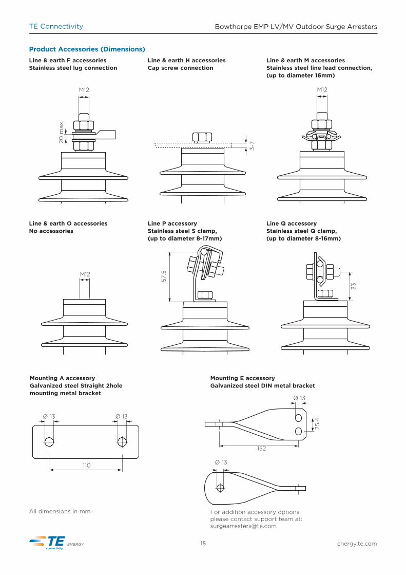
M12
20 m
axLine & earth F accessoriesStainless steel lug connection
Product Accessories (Dimensions)Line & earth M accessoriesStainless steel line lead connection, (up to diameter 16mm)
M12
57.5
Line P accessoryStainless steel S clamp, (up to diameter 8-17mm)
33
Line Q accessoryStainless steel Q clamp, (up to diameter 8-16mm)
Ø 13
25.4
152
Ø 13
Mounting E accessoryGalvanized steel DIN metal bracket
Ø 13 Ø 13
110
Mounting A accessoryGalvanized steel Straight 2hole mounting metal bracket
For addition accessory options, please contact support team at: [email protected]
Line & earth H accessoriesCap screw connection
3-7
Line & earth O accessoriesNo accessories
M12
All dimensions in mm.
energy.te.com15

TE Connectivity Bowthorpe EMP LV/MV Outdoor Surge Arresters
energy.te.com 16
Product Accessories (Dimensions)
25
M12
Ø 13
14.5
25.4
152
Line B & E accessoriesTracking and erosion resistantbird protection cover
Line D & E accessoriesEarth lead disconnect
Mounting C accessoryStainless steel DIN metal bracket
All dimensions in mm.
For addition accessory options, please contact support team at: [email protected]
Galvanized steel NEMA cross arm mounting bracket
57
68.5-101.5
105-
131
9

TE Connectivity Bowthorpe EMP LV/MV Outdoor Surge Arresters
Product Accessories (Dimensions)
Ø 13
202
157.5
Mounting B accessoryInsulating brackets
Ur > 24kVUc > 19kV
146
101.5
Ø 13
Ur 0-12.5kVUc 0-10kV
All dimensions in mm.
For addition accessory options, please contact support team at: [email protected]
129.5
Ø 13
174
Ur 13-24kVUc 10.1-19kV
energy.te.com17

TE Connectivity Bowthorpe EMP LV/MV Outdoor Surge Arresters
energy.te.com 18
Protection system CLX for medium-voltage covered conductor overhead linesAn absolute must when covered con-ductor systems are used, CLX prevents covered conductors from melting and falling down to earth when lightning strikes generating overvoltages in overhead lines. CLX guides the light-ning discharge current to ground, preventing the insulator from flashing over and stops the high energy of the power frequency follow-on current. In addition, the CLX protected over-head lines should see a considerable reduction in power supply interruptions
Generic technical data CLX-xx series 12-36 kV UcRated discharge current (8/20µs) 10 kAOperating duty impulse withstand current (4/10µs) 65 kAHigh current short circuit: (pre-failing method) 25 kA(Safe non-shattering failure mode) Service conditions Ambient temperature - 60°C to + 60°C Mechanical strength data Cantilever 250 NmTorque 50 Nm
Typical setup for 12 kV rated system Voltage applications
>100
191
47
CLX Surge Arresters for Covered Conductors during storms. This makes it attractive also for bare conductor distribution systems. Even in case of accidental bridging CLX will not cause a phase-to-ground fault. The CLX device contains a Metal Oxide Resistive Element and an external series gap to isolate the Metal Oxide Resistive Element from the system. The CLX device is installed next to the line / post insulators and can be adapted to most system appli-cations. The series gap will be realized by different brackets, electrodes and connectors. TE Connectivity offers engineering support to optimize the use of CLX.
Standard electrical dataCLX Lightning current Steep lightning current Lightning Impulse Spark-over Voltage impulse 8/20 µs: impulse 1/20 µs: Standard: Steep-wet: 5 kA 10 kA 20 kA 10 kA 1.2/50 µs 1000 kV/µs CLX-12S 29.3 31.5 35.6 34.6 97 175CLX-24S 48.9 52.5 59.4 57.6 100 263CLX-36S 78.2 84.0 95.0 92.2 130 294
Metal oxide resistive elements housing parametersCLX-xxS Sheds Impulse voltage Power frequency Flash over Creepage Height Weight 1.2/50µs withstand distance length L (approx) voltage, wet (kV) (kV) (mm) (mm) (mm) (kg)CLX-12S 5 145 47 176 379 183 1.4CLX-24S 7 165 57 214 503 220 1.65CLX-36S 11 200 80 293 755 299 2.1

energy.te.com19
TE Connectivity Bowthorpe EMP LV/MV Outdoor Surge Arresters
Sparkover Voltage
Residual Voltage
100 kV
50 kV
1 10 20 µs
Sparkover Voltage
Residual Voltage
150 kV
50 kV
100 kV
1 10 20 µs
10 kV System 20 kV System
Protection system EGLA for medium-voltage transformer overhead linesThis type of surge arresters is designed to protect the insulator assembly at transformers from the lightning over-voltages. It is connected in parallel to the insulator assembly. It is defined as a device that contains a non-linear metal oxide resistor element in its arrester body (EGLA) and an external
Without EGLA Protecting the network from an overvoltage without EGLA can result in a temporary loss of power. The duration of power loss depends on the current protection settings.
With EGLALightning protection with the EGLA arrester. The EGLA will maintain the integrity of the network.
The pictures below show different constructions of the EGLA system.
EGLA Externally Gapped Line Arrester series gap to isolate the EGLA from the system. The protection is accom-plished by raising the spark-over level of the external series gap to a level that isolates the arrester from power frequency overvoltages and from the worst case switching overvoltages expected on the line which it is applied. The external series gap acts as an iso-lating apparatus in the event of arrester body failure.

energy.te.com 20
TE Connectivity Bowthorpe EMP LV/MV Outdoor Surge Arresters
TVC Transient Voltage Clampers
M 12 Stainlesssteel termination
Zinc oxidevaristor core
UV stable tracking resistant
housing
Current-voltage characterisitc for ZnO varistor
Current (Amps/mm2)
20°C
60°C
Continuous operating voltage
Protection against Switching over-voltages
Rated voltage
Protection against Lightning over-voltages
Pre-break-down region
Breakdown region High currentregion
120°C
Vo
ltag
e (V
/mm
)
Transient Voltage Clampers are designed under the same principle as LV voltage surge arresters; however applications are more specific.
IntroductionIn the UK where severe lightning is often accompanied by poor pole earthing resistance, the secondary LV distribution system is subjected tohigh voltage surges due to lightning current seeking alternate ground paths through the low-voltage circuits. The typical mode of failure of a pole mounted transformer is for the low voltage winding to flash over to the transformer tank due to the relatively high voltage developed across the pole earth resistance. The high voltage arrester does not prevent this type of failure. However, to remove this source of failure (or back flash over) a TVC may be placed between the neutral bushing and the tank.
What is a transient voltage clamper, TVCA TVC is used to protect against the internal failure of a pole mounted transformer (PMT) due to “back flashover” between the transformer tank and the LV winding bushing. A “back flashover” on a PMT will cause permanent damage to the transformer internal solid insulation.
Conditions of use1) TVC’s are useful when there is very high resistivity pole grounding con-ditions e.g. hot, sandy, rocky ground. Under these soil conditions an earth resistance of 10 ohms or less may be difficult to achieve; resistance maybe variable throughout the year.2) TVC’s are useful when the LV earth “downstream” from the PMT is lower than at the pole earth resistance. 3) Best used in conjunction with HV and LV surge arresters (cannot be used instead).
Principle of operationTVCs incorporate a gapless metal oxide varistor, MOV design that under steady state conditions maintains the line-to-ground voltage across the TVCs terminals. When overvoltagesoccur, the TVC conducts current to earth, limiting the overvoltage to below the required protection levels. Upon passage of the overvoltage condition, the TVC returns to a highly non-linear steady state condition that conducts very minimal 10’s of Hz power current.
Generic technical dataTVC-1 4.8 kV Uc / 6 kV Ur
Rated discharge current (8/20µs) 5 kA
Operating duty impulse withstand current (4/10µs) 65 kA
High current short circuit (pre-failing method) 25 kA(Safe non-shattering failure mode)
Service conditions Ambient temperature - 40°C to + 40°C

energy.te.com21
TE Connectivity Bowthorpe EMP LV/MV Outdoor Surge Arresters
The Bowthorpe EMP SPG4 Spark Gap is designed for use with traction circuits to provide virtually instantaneous protection of both equipment and personnel from power system faults. The unit also provides protection against lightning generated voltages which would otherwise cause damage to signalling and cable circuits.
The SPG4 is constructed in stainless steel of rugged design allowing the SPG to be installed in harsh environ-ments such as track side locations without additional weather protection.
Max open circuit voltage 300v RMS
Min spark over voltage 50/60Hz 400v RMS
Max spark over voltage 50/60HZ 900v RMS
0.1 second current carrying capacity 10kA
0.5 second current carrying capacity 5kA
Time to gap short circuit 5 microseconds
High current withstand based on 4/10 microsecond wave 65kA (2 shots)
Number of operations based on 10kA 8/20 microsecond wave 20
Typical applications• Protection between overhead catenary
structure earth and system earth.• Protection between indirectly
earthed systems and system or ground earth.
• Protection of single bonded power cable circuits.
• Protection of intermediate junction on cross bonded power cable systems.
• Protection of cathodic protection power supplies.
• Protection of low voltage DC power supplies.
Features• Suitable for use on circuits where
standing/induced voltages do not exceed 110v RMS.
• Fast operation – Typical 5 microseconds with 11kA fault current.
• Internal spark gap module unit can be replaced using a special tool after fault current operation.
• Fail safe feature ensures safety to personnel and equipment.
• Service proven performance.• High internal impedance with low
capacitance – does not interfere with track signalling circuits.
SPG4 Spark Gap Surge Arresters
Technical characteristicsThe SPG4 Spark Gap operates to short circuit with power system fault current. All lightning induced overvoltages are passed to earth without permanent connection to earth
M12 stainless steel line stud
Stainless steel outer housing
35 mm
86 mm
44 mm
Insulator
Stainless steel shakeproof washers and lock nuts
Stainless steel shakeproof washers and lock nuts
M12 stainless steel earth stud
50 mm

energy.te.com 22
TE Connectivity Bowthorpe EMP LV/MV Outdoor Surge Arresters
Contact us at: [email protected]
Other products and brochures available from TE Energy
Asset protection
Low-voltage surge arresters
Insulation enhancement systems for substations and overhead lines. Designed to prevent unplanned outages due to accidential bridging.
LV arresters are used to provide protection for LV overhead lines, consumer in-house supplies, distribution tranformers and other applicances.
Metal oxide varistor distribution arresters for indoor and outdoor applications for protection of overhead lines, DC locomotives and switchgear applications.
Porcelain and polymeric series parallel and single column contructed arresters for protection of transmission systems up to 550 kV.
Insulators and insulating components/housings providing reliable solutions for power utilities and railway customers with installations in high pollution environments and applications up to 400 kV.
Insulators for applications up to system voltages of 132 kV. This range of insulators offers a cost-effective solution for low and medium polluted environments.
Medium-voltage surge arresters
High-voltage surge arresters
Polymeric insulators
Porcelain insulators
Contact us at: [email protected]
Contact us at: [email protected]
Contact us at: [email protected]
Contact us at: [email protected]
Contact us at: [email protected]

About TE Connectivity
TE Connectivity is a global, $14 billion company that designs and manufactures approximately 500,000 products that connect and protect the flow of power and data inside the products that touch every aspect of our lives. Our nearly 100,000 employees partner with customers in virtually every industry – from consumer electronics, energy and healthcare, to automotive, aerospace and communication networks – enabling smarter, faster, better technologies to connect products to possibilities.
More information on TE Connectivity can be found at: www.te.com
LV/MV Product ManagementTE Connectivity LimerickInternational Science CentreBlock 1, University Of Limerick (N.T.P.)CastletroyCo. Limerick. Ireland
Phone: + 353 61 470 800Email: [email protected]
energy.te.com
EP
P 1
09
8 4
/14
While TE Connectivity (TE) has made every reasonable effort to ensure the accuracy of the information in this catalog, TE does not guarantee that it is error-free, nor does TE make any other representation, warranty or guarantee that the information is accurate, correct, reliable or current. TE reserves the right to make any adjustments to the information contained herein at any time without notice. TE expressly disclaims all implied warranties regarding the information contained herein, including, but not limited to, any implied warranties of merchantability or fitness for a particular purpose. The dimensions in this catalog are for reference purposes only and are subject to change without notice. Specifications are subject to change without notice. Consult TE for the latest dimensions and design specifications. Bowthorpe EMP, TE Connectivity and TE connectivity (logo) are trademarks. Other logos, product and company names mentioned herein may be trademarks of their respective owners. © 2014 TE Connectivity family of companies. All Rights Reserved
TE Energy – innovative and economical solutions for the electrical power industry: cable accessories, connectors & fi ttings, insulators & insulation, surge arresters, switching equipment, street lighting, power measurement and control.