bow and stern sinkage coefficients for cargo ships in
TRANSCRIPT

Bow and Stern Sinkage Coefficients for Cargo Ships in Shallow Open Water
The 3rd-place winner of the 2017 PIANC De Paepe-Willems Award
1
Bow and Stern Sinkage Coefficients for Cargo Ships in Shallow Open Water
Jeong Hun Ha1* and Tim Gourlay2 1Centre for Marine Science and Technology, Curtin University, Perth, Australia
2Perth Hydro Pty Ltd, Perth, Australia
*Lead author: [email protected]
Abstract
In this paper, we develop sinkage coefficients for ships in shallow open water, or harbour
approach channels with minimal transverse restriction. These sinkage coefficients may be
used for under-keel clearance management by ports, pilots, and deck officers. The
coefficients are calculated using slender-body shallow-water theory applied to 12 published
hull forms. Results are condensed into sinkage coefficient ranges for container ships, oil
tankers, bulk carriers, and membrane LNG carriers. Limitations on use of the coefficients
are suggested, based on ship and navigation channel dimensions. Examples are given for
container ships, bulk carriers, and LNG carriers in Australian ports.
Keywords: Sinkage; Approach channel; Shallow water; Ship hulls; Ship under-keel clearance
1. Introduction
When a ship is under way in shallow calm water, it experiences a downward sinkage and
dynamic trim change, which are collectively called “squat”. This is a Bernoulli effect, whereby
the free surface drops as water is accelerated along the sides of the ship. The ship then sinks
hydrostatically into its own wave trough, bringing it closer to the seabed. Squat has been a
significant contributing factor in several grounding incidents (Nautical Institute, 2015).
The recent PIANC guidelines for harbour approach channels (Permanent International
Association of Navigation Congresses (PIANC), 2014) contain information on suitable squat
allowances for different types of ships and channels. The methods are semi-empirical, and
several (Hooft, 1974; Huuska, 1976; ICORELS, 1980; Millward, 1992) are based on the
slender-body analysis of Tuck (1966) for ships in shallow open water. According to that theory,
the midship, bow, and stern sinkage may be written
2
2
2
1 h
h
PP
s_midmid
F
F
LCS
(1)
2
2
2
1h
h
PP
s_bowbow
F
F
LCS
(2)
Bow and Stern Sinkage Coefficients for Cargo Ships in Shallow Open Water
The 3rd-place winner of the 2017 PIANC De Paepe-Willems Award
2
2
2
2
1 h
h
PP
s_sternstern
F
F
LCS
(3)
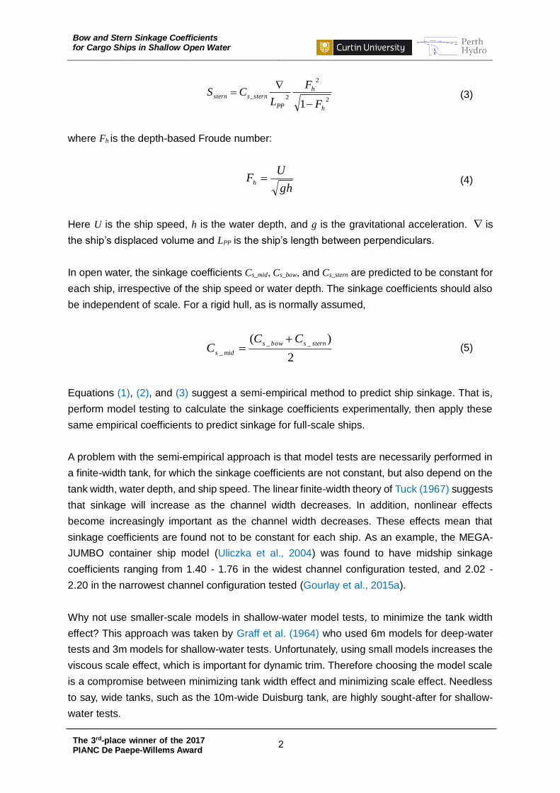
where Fh is the depth-based Froude number:
gh
UF
h (4)
Here U is the ship speed, h is the water depth, and g is the gravitational acceleration. is
the ship’s displaced volume and LPP is the ship’s length between perpendiculars.
In open water, the sinkage coefficients Cs_mid, Cs_bow, and Cs_stern are predicted to be constant for
each ship, irrespective of the ship speed or water depth. The sinkage coefficients should also
be independent of scale. For a rigid hull, as is normally assumed,
2
)(__
_
sternsbows
mids
CCC
(5)
Equations (1), (2), and (3) suggest a semi-empirical method to predict ship sinkage. That is,
perform model testing to calculate the sinkage coefficients experimentally, then apply these
same empirical coefficients to predict sinkage for full-scale ships.
A problem with the semi-empirical approach is that model tests are necessarily performed in
a finite-width tank, for which the sinkage coefficients are not constant, but also depend on the
tank width, water depth, and ship speed. The linear finite-width theory of Tuck (1967) suggests
that sinkage will increase as the channel width decreases. In addition, nonlinear effects
become increasingly important as the channel width decreases. These effects mean that
sinkage coefficients are found not to be constant for each ship. As an example, the MEGA-
JUMBO container ship model (Uliczka et al., 2004) was found to have midship sinkage
coefficients ranging from 1.40 - 1.76 in the widest channel configuration tested, and 2.02 -
2.20 in the narrowest channel configuration tested (Gourlay et al., 2015a).
Why not use smaller-scale models in shallow-water model tests, to minimize the tank width
effect? This approach was taken by Graff et al. (1964) who used 6m models for deep-water
tests and 3m models for shallow-water tests. Unfortunately, using small models increases the
viscous scale effect, which is important for dynamic trim. Therefore choosing the model scale
is a compromise between minimizing tank width effect and minimizing scale effect. Needless
to say, wide tanks, such as the 10m-wide Duisburg tank, are highly sought-after for shallow-
water tests.

Bow and Stern Sinkage Coefficients for Cargo Ships in Shallow Open Water
The 3rd-place winner of the 2017 PIANC De Paepe-Willems Award
3
Some authors have tried to capture the dependence on channel width through empirical
corrections to the sinkage coefficients (PIANC, 2014). While this might work well for the ship
models and channels used to develop the correction, the physics might not be adequately
captured to be able to apply these methods to a wide range of ships.
We would recommend that complete numerical simulations be performed for ships in channels.
For moderate-width channels, the linear slender-body theory of Tuck (1967) may be used; for
narrow channels, the nonlinear Rankine-source method (e.g. von Graefe, 2014) may be used;
for very narrow channels, the nonlinear hydraulic theory of Gourlay (1999) may be used.
RANS methods are also becoming increasingly common for modelling ship sinkage and trim,
especially in confined waterways (Mucha et al., 2014).
Here, we concentrate on waterways with minimal transverse restriction, such as open
waterways or dredged channels, which are common for port approach channels on the
Australian continental shelf. For these types of waterways, we develop sinkage coefficients
that may be used for under-keel clearance management. The coefficients are calculated using
the slender-body theory of Tuck (1966) for open water; Tuck (1967) for canals; and Beck et al.
(1975) for dredged channels. The methods are implemented in the computer code
“ShallowFlow” developed at the Centre for Marine Science and Technology, Curtin University
(Gourlay, 2014). For wide channels, slender-body theory has been shown to give good results
for container ships at model scale (Gourlay et al., 2015a), container ships at full scale (Gourlay,
2008a), bulk carriers and tankers at model scale (Gourlay, 2006; Gourlay et al., 2016), and
bulk carriers and tankers at full scale (Gourlay, 2008b; Ha et al., 2016).
2. Cargo ship types and representative ship models
While lines plans for merchant cargo ships are generally confidential, many ship hull forms for
research objectives have been developed over the years. Here, 12 published representative
ship models have been chosen for analysis. These fall into the categories of container ships,
bulk carriers, oil tankers, or membrane LNG carriers. Oil tankers and bulk carriers are grouped
together due to parallels in hull shape between them.
Ships carrying different types of cargo have evolved to have different hull shapes. Shipping
containers are fairly low density and need to be transported quickly, so container ships tend
to have low block coefficient, to maximize waterplane area for their displacement and give an
efficient hull shape. Bulk carriers and tankers have high-density cargo with less requirement
for speed, so the hull shapes tend to have high block coefficient, to maximize deadweight
capacity at the expense of hull efficiency. Membrane LNG carriers are generally in between
container ships and tankers in terms of hull shape and block coefficient, but have shallower
draught because of their low-density cargo.

Bow and Stern Sinkage Coefficients for Cargo Ships in Shallow Open Water
The 3rd-place winner of the 2017 PIANC De Paepe-Willems Award
4
In this paper, we shall be focussing only on container ships, bulk carriers, oil tankers, and
membrane LNG carriers, which are the hull types we shall be analysing. Therefore, these
results are not directly applicable to other cargo ship types, such as Ro-Ro vessels, car
carriers, livestock carriers, Moss LNG carriers, LPG carriers, and warships.
The container ships modelled are:
“Duisburg Test Case” (“DTC”, 355m LPP), designed by the University of Duisburg-
Essen, Germany in 2012, representative of a 14,000 TEU Post-Panamax container
ship (El Moctar et al., 2012)
“KRISO Container Ship” (“KCS”, 230m LPP), designed by Korean Research Institute
Ships and Ocean Engineering (KRISO) in 1997, representative of a 3,600 TEU
Panamax container ship (Lee et al., 2003)
“JUMBO” (320m LPP), designed by SVA Potsdam, Germany in 1995, representative of
a 5,500 TEU Post-Panamax container ship (Uliczka et al., 2004)
“MEGA-JUMBO” (360m LPP), designed by VWS Berlin, Germany in 2001, the design
ship for the Jade Weser port in Germany, representative of a 12,000 TEU Post-
Panamax container ship (Uliczka et al., 2004)
“FHR Ship D” (291.13m LPP), designed by Flanders Hydraulics Research and Ghent
University, Belgium in 1996-2000, representative of a Post-Panamax container ship
(Gourlay et al., 2015b; Vantorre and Journée, 2003)
“FHR Ship F” (190m LPP), designed by Flanders Hydraulics Research and Ghent
University, Belgium in 1996-2000, representative of a Panamax container ship
(Gourlay et al., 2015b; Vantorre and Journée, 2003)
The oil tankers modelled are:
“KRISO Very Large Crude Oil Carrier” (“KVLCC”, 320m LPP), designed by Korean
Research Institute Ships and Ocean Engineering (KRISO) in 1997, representative of
a 300,000 DWT oil tanker (Larsson et al., 2003; Van et al., 1998)
“KRISO Very Large Crude Oil Carrier 2” (“KVLCC2”, 320m LPP), designed by Korean
Research Institute Ships and Ocean Engineering (KRISO) in 1997, representative of
a 300,000 DWT oil tanker, the second version of the KVLCC with more U-shaped stern
frame-lines (Larsson et al., 2003; Van et al., 1998)
The bulk carriers modelled are:
“Japan 1704B standard series” (6m model LPP), designed by National Maritime
Research Institute (NMRI, former Ship Research Institute of Japan), representative of
a Panamax bulk carrier (Yokoo, 1966)

Bow and Stern Sinkage Coefficients for Cargo Ships in Shallow Open Water
The 3rd-place winner of the 2017 PIANC De Paepe-Willems Award
5
“Japan Bulk Carrier” (“JBC”, 280m LPP), designed by National Maritime Research
Institute (NMRI, former Ship Research Institute of Japan), Yokohama National
University, and Ship Building Research Centre of Japan, representative of a Post-
Panamax bulk carrier (NMRI, 2015)
“FHR Ship G” (180m LPP), designed by Flanders Hydraulics Research and Ghent
University, Belgium in 1996-2000, representative of a Panamax bulk carrier (Gourlay
et al., 2015b; Vantorre and Journée, 2003)
The membrane LNG carrier modelled is:
“KRISO Liquefied Natural Gas Carrier” (“KLNG”, 266m LPP), designed by Korean
Research Institute Ships and Ocean Engineering (KRISO) in 2003, representative of
a 138,000 m3 membrane LNG carrier (Van et al., 2003, 2006)
In this paper, hull shapes of the above 12 ships have been developed from supplied IGES files
and the published lines plans using Rhino, AutoCAD, and Maxsurf Modeler. Calculated details
of the modelled vessels are given in Table 1 and Table 2. Note that some of the particulars
have been calculated from the modelled vessels and are approximate. Longitudinal centre of
buoyancy (LCB) and longitudinal centre of floatation (LCF) are given as % of LPP forward of
aft perpendicular (AP). Block coefficient is the ratio of displacement to (LPP.Beam.Draught).
Dimensions of the Japan 1704B are at model scale, as no full-scale dimensions were specified.
Table 1.
Details of the container ships used for numerical calculations.
Particulars
Container ships
DTC KCS JUMBO MEGA-
JUMBO
FHR
Ship D
FHR
Ship F
LPP (m) 355.00 230.00 320.00 360.00 291.13 190.00
Beam (m) 51.00 32.20 40.00 55.00 40.25 32.00
Draught (m) 14.50 10.80 14.50 16.00 15.00 11.60
Block coefficient (-) 0.660 0.650 0.721 0.681 0.604 0.600
Displacement (m3) 173,337 52,013 133,901 215,775 106,226 42,338
Max. section area
(m2) 730.02 342.42 564.22 867.53 593.13 365.02
LCB (%) 49.04 48.52 49.30 49.97 47.05 47.74
LCF (%) 45.38 44.33 45.84 49.12 44.54 45.43
Bow and Stern Sinkage Coefficients for Cargo Ships in Shallow Open Water
The 3rd-place winner of the 2017 PIANC De Paepe-Willems Award
6
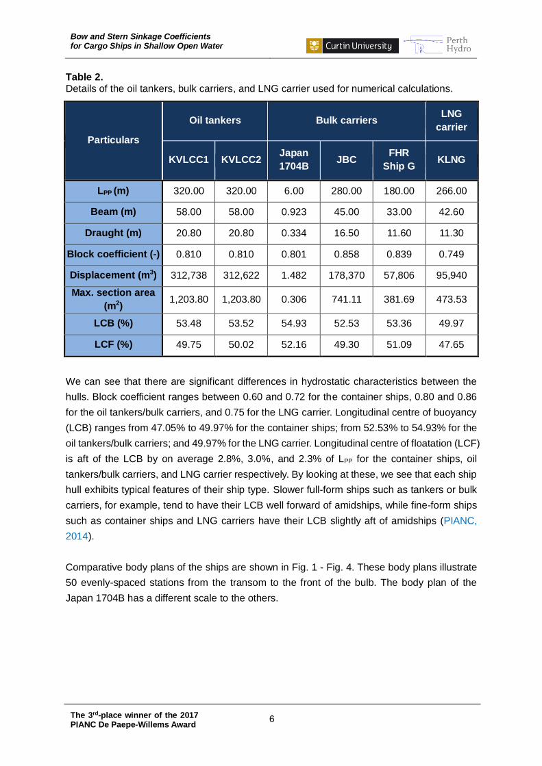
Table 2. Details of the oil tankers, bulk carriers, and LNG carrier used for numerical calculations.
Particulars
Oil tankers Bulk carriers LNG
carrier
KVLCC1 KVLCC2 Japan
1704B JBC
FHR
Ship G KLNG
LPP (m) 320.00 320.00 6.00 280.00 180.00 266.00
Beam (m) 58.00 58.00 0.923 45.00 33.00 42.60
Draught (m) 20.80 20.80 0.334 16.50 11.60 11.30
Block coefficient (-) 0.810 0.810 0.801 0.858 0.839 0.749
Displacement (m3) 312,738 312,622 1.482 178,370 57,806 95,940
Max. section area
(m2) 1,203.80 1,203.80 0.306 741.11 381.69 473.53
LCB (%) 53.48 53.52 54.93 52.53 53.36 49.97
LCF (%) 49.75 50.02 52.16 49.30 51.09 47.65
We can see that there are significant differences in hydrostatic characteristics between the
hulls. Block coefficient ranges between 0.60 and 0.72 for the container ships, 0.80 and 0.86
for the oil tankers/bulk carriers, and 0.75 for the LNG carrier. Longitudinal centre of buoyancy
(LCB) ranges from 47.05% to 49.97% for the container ships; from 52.53% to 54.93% for the
oil tankers/bulk carriers; and 49.97% for the LNG carrier. Longitudinal centre of floatation (LCF)
is aft of the LCB by on average 2.8%, 3.0%, and 2.3% of LPP for the container ships, oil
tankers/bulk carriers, and LNG carrier respectively. By looking at these, we see that each ship
hull exhibits typical features of their ship type. Slower full-form ships such as tankers or bulk
carriers, for example, tend to have their LCB well forward of amidships, while fine-form ships
such as container ships and LNG carriers have their LCB slightly aft of amidships (PIANC,
2014).
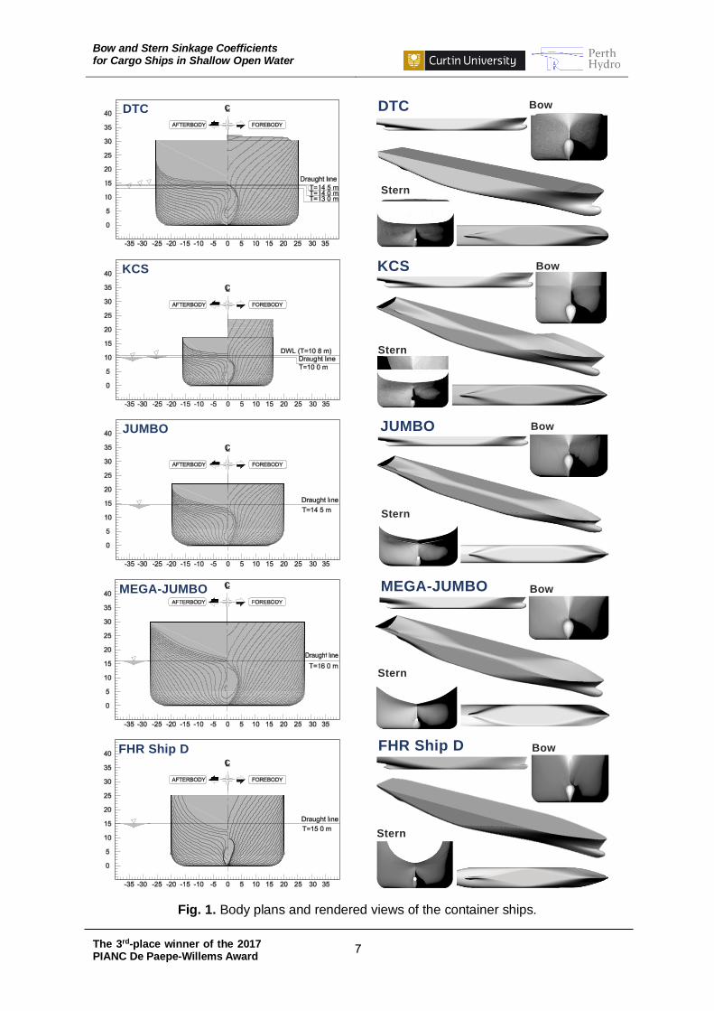
Comparative body plans of the ships are shown in Fig. 1 - Fig. 4. These body plans illustrate
50 evenly-spaced stations from the transom to the front of the bulb. The body plan of the
Japan 1704B has a different scale to the others.
Bow and Stern Sinkage Coefficients for Cargo Ships in Shallow Open Water
The 3rd-place winner of the 2017 PIANC De Paepe-Willems Award
7
Fig. 1. Body plans and rendered views of the container ships.
DTC Bow
Stern
DTC
KCS KCS
Stern
Bow
JUMBO Bow
Stern
JUMBO
MEGA-JUMBO Bow
Stern
MEGA-JUMBO
FHR Ship D Bow
Stern
FHR Ship D
Bow and Stern Sinkage Coefficients for Cargo Ships in Shallow Open Water
The 3rd-place winner of the 2017 PIANC De Paepe-Willems Award
8
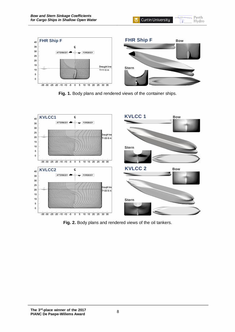
Fig. 1. Body plans and rendered views of the container ships.
Fig. 2. Body plans and rendered views of the oil tankers.
FHR Ship F Bow
Stern
FHR Ship F
KVLCC1 Bow
Stern
KVLCC 1
KVLCC2 Bow
Stern
KVLCC 2
Bow and Stern Sinkage Coefficients for Cargo Ships in Shallow Open Water
The 3rd-place winner of the 2017 PIANC De Paepe-Willems Award
9
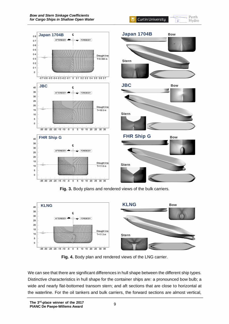
Fig. 3. Body plans and rendered views of the bulk carriers.
Fig. 4. Body plan and rendered views of the LNG carrier.
We can see that there are significant differences in hull shape between the different ship types.
Distinctive characteristics in hull shape for the container ships are: a pronounced bow bulb; a
wide and nearly flat-bottomed transom stern; and aft sections that are close to horizontal at
the waterline. For the oil tankers and bulk carriers, the forward sections are almost vertical,
Japan 1704B Bow
Stern
Japan 1704B
JBC Bow
Stern
JBC
FHR Ship G Bow
Stern
FHR Ship G
KLNG
Stern
BowKLNG
Bow and Stern Sinkage Coefficients for Cargo Ships in Shallow Open Water
The 3rd-place winner of the 2017 PIANC De Paepe-Willems Award
10
and aft sections are not far from vertical, at the waterline. The oil tankers and bulk carriers
have smaller transoms and sharper bow bulbs than the container ships. The KLNG is generally
in between the container ships and the oil tankers with regard to hull shape.
In addition, Fig. 1 - Fig. 4 show the bow, stern, profile, bottom, and perspective views of the
modelled ships, emphasizing each ship type’s features in hull shape. We see that the container
ship hulls have streamlined forward and aft sections, whereas the hulls of the oil tankers and
bulk carriers are very-block with a long parallel midbody. The KLNG hull has a long parallel
midbody and streamlined forward and aft sections.
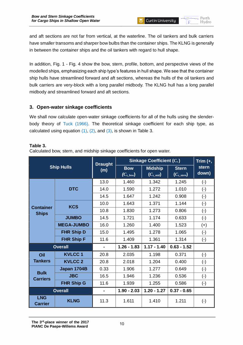
3. Open-water sinkage coefficients
We shall now calculate open-water sinkage coefficients for all of the hulls using the slender-
body theory of Tuck (1966). The theoretical sinkage coefficient for each ship type, as
calculated using equation (1), (2), and (3), is shown in Table 3.
Table 3. Calculated bow, stern, and midship sinkage coefficients for open water.
Ship Hulls Draught
(m)
Sinkage Coefficient (Cs ) Trim (+,
stern
down) Bow
(Cs_bow)
Midship
(Cs_mid)
Stern
(Cs_stern)
Container
Ships
DTC
13.0 1.460 1.342 1.245 (-)
14.0 1.590 1.272 1.010 (-)
14.5 1.647 1.242 0.908 (-)
KCS 10.0 1.643 1.371 1.144 (-)
10.8 1.830 1.273 0.806 (-)
JUMBO 14.5 1.721 1.174 0.633 (-)
MEGA-JUMBO 16.0 1.260 1.400 1.523 (+)
FHR Ship D 15.0 1.495 1.278 1.065 (-)
FHR Ship F 11.6 1.409 1.361 1.314 (-)
Overall - 1.26 - 1.83 1.17 - 1.40 0.63 - 1.52
Oil
Tankers
KVLCC 1 20.8 2.035 1.198 0.371 (-)
KVLCC 2 20.8 2.018 1.204 0.400 (-)
Bulk
Carriers
Japan 1704B 0.33 1.906 1.277 0.649 (-)
JBC 16.5 1.946 1.236 0.536 (-)
FHR Ship G 11.6 1.939 1.255 0.586 (-)
Overall - 1.90 - 2.03 1.20 - 1.27 0.37 - 0.65
LNG
Carrier KLNG 11.3 1.611 1.410 1.211 (-)

Bow and Stern Sinkage Coefficients for Cargo Ships in Shallow Open Water
The 3rd-place winner of the 2017 PIANC De Paepe-Willems Award
11
We see that hull shape is critical for these results. The bow sinkage coefficient for the group
of the oil tankers and bulk carriers, which ranges between 1.90 and 2.03, on average, is 26%
larger than that of the container ships, and 22% larger than the LNG carrier’s value. The
midship sinkage coefficient ranges from 1.17 for the JUMBO of the container ship type through
to 1.41 for the KLNG. In considering the difference between Cs_bow and Cs_stern for the ships,
dynamic trim for the container ships is generally quite small, but some trim quite strongly bow-
down. Similar results were found in full-scale measurements on 16 container ships in Hong
Kong (Gourlay and Klaka, 2007).
Theoretically, the sinkage coefficient in open water is constant for each ship, regardless of the
ship speed or water depth, but does depend on hull shape. Therefore, we offer a guideline
based on Table 3 for making a choice of the sinkage coefficient corresponding to different ship
types. These recommended sinkage coefficients are shown in Table 4.
Table 4.
Recommended sinkage coefficients with respect to ship types in open water.
Ship Types Sinkage Coefficient (Cs )
Bow (Cs_bow) Stern (Cs_stern) Max (Cs_max)
Container Ships 1.3 - 1.8 0.6 - 1.5 1.8
Oil Tankers & Bulk Carriers 1.9 - 2.0 0.4 - 0.7 2.0
LNG Carriers 1.6 1.2 1.6
4. Limitations on using the sinkage coefficients for different bathymetries
If we wish to put limitations on using the sinkage coefficients, we can compare how the sinkage
coefficient is changing with channel dimensions. We consider three idealised types of
approach channel, as defined in PIANC (2014), and shown in Fig. 5.
Fig. 5. Channel configurations: unrestricted (open-water); restricted (dredged); and canal.
h
Unrestricted Channel
h
W
hT
Slope n = run/rise
Restricted Channel
h
W
Slope n = run/rise
Canal
Bow and Stern Sinkage Coefficients for Cargo Ships in Shallow Open Water
The 3rd-place winner of the 2017 PIANC De Paepe-Willems Award
12
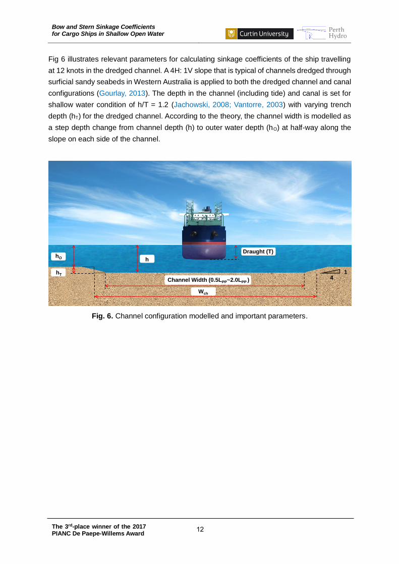
Fig 6 illustrates relevant parameters for calculating sinkage coefficients of the ship travelling
at 12 knots in the dredged channel. A 4H: 1V slope that is typical of channels dredged through
surficial sandy seabeds in Western Australia is applied to both the dredged channel and canal
configurations (Gourlay, 2013). The depth in the channel (including tide) and canal is set for
shallow water condition of h/T = 1.2 (Jachowski, 2008; Vantorre, 2003) with varying trench
depth (hT) for the dredged channel. According to the theory, the channel width is modelled as
a step depth change from channel depth (h) to outer water depth (hO) at half-way along the
slope on each side of the channel.
Fig. 6. Channel configuration modelled and important parameters.
Channel Width (0.5LPP~2.0LPP )
hO h
Draught (T)
Wch
14
hT
Bow and Stern Sinkage Coefficients for Cargo Ships in Shallow Open Water
The 3rd-place winner of the 2017 PIANC De Paepe-Willems Award
13
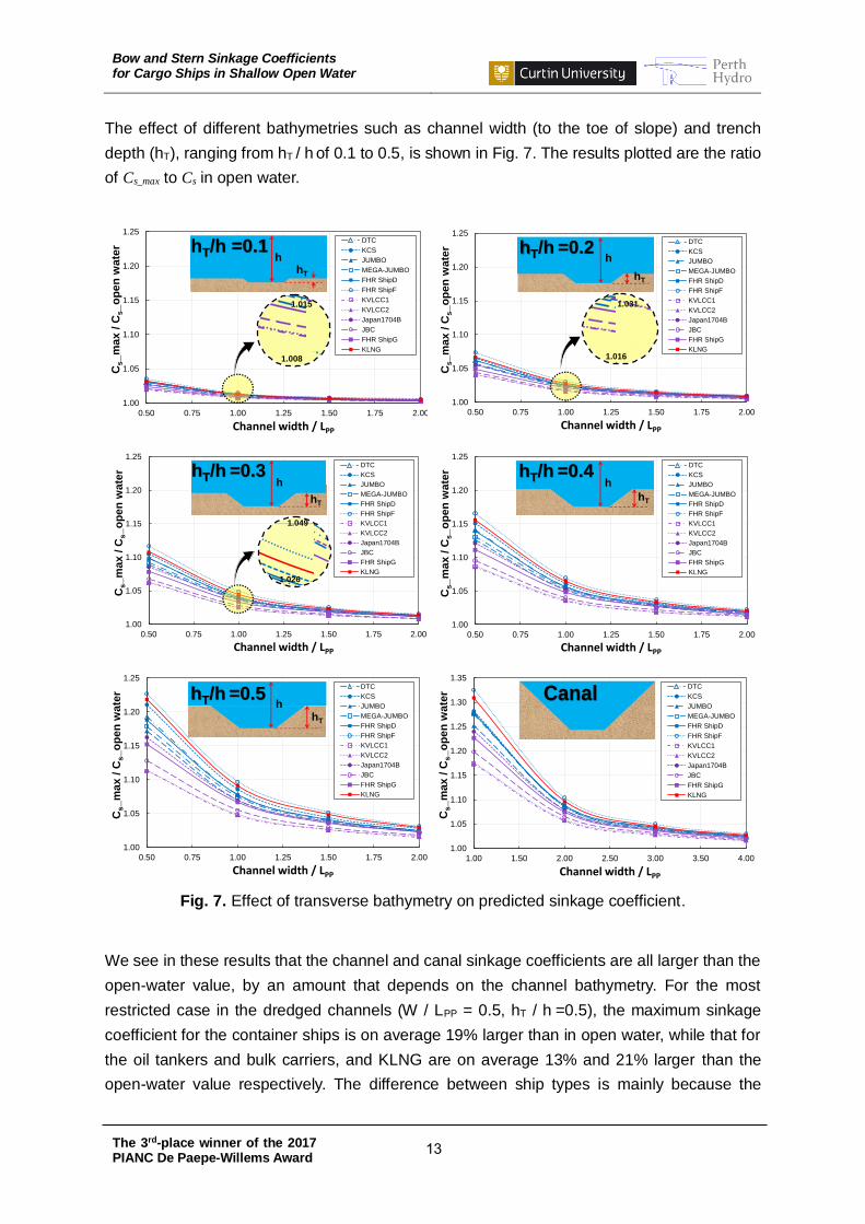
The effect of different bathymetries such as channel width (to the toe of slope) and trench
depth (hT), ranging from hT / h of 0.1 to 0.5, is shown in Fig. 7. The results plotted are the ratio
of Cs_max to Cs in open water.
Fig. 7. Effect of transverse bathymetry on predicted sinkage coefficient.
We see in these results that the channel and canal sinkage coefficients are all larger than the
open-water value, by an amount that depends on the channel bathymetry. For the most
restricted case in the dredged channels (W / LPP = 0.5, hT / h =0.5), the maximum sinkage
coefficient for the container ships is on average 19% larger than in open water, while that for
the oil tankers and bulk carriers, and KLNG are on average 13% and 21% larger than the
open-water value respectively. The difference between ship types is mainly because the
1.00
1.05
1.10
1.15
1.20
1.25
0.50 0.75 1.00 1.25 1.50 1.75 2.00
Cs_m
ax /
Cs_o
pen
wate
r
Channel width / LPP
DTC
KCS
JUMBO
MEGA-JUMBO
FHR ShipD
FHR ShipF
KVLCC1
KVLCC2
Japan1704B
JBC
FHR ShipG
KLNG
hhT/h =0.1
hT
1.015
1.008
1.00
1.05
1.10
1.15
1.20
1.25
0.50 0.75 1.00 1.25 1.50 1.75 2.00
Cs_m
ax /
Cs_o
pen
wate
r
Channel width / LPP
DTC
KCS
JUMBO
MEGA-JUMBO
FHR ShipD
FHR ShipF
KVLCC1
KVLCC2
Japan1704B
JBC
FHR ShipG
KLNG
hhT/h =0.2
hT
1.031
1.016
1.00
1.05
1.10
1.15
1.20
1.25
0.50 0.75 1.00 1.25 1.50 1.75 2.00
Cs_
max
/ C
s_
op
en
wa
ter
Channel width / LPP
DTC
KCS
JUMBO
MEGA-JUMBO
FHR ShipD
FHR ShipF
KVLCC1
KVLCC2
Japan1704B
JBC
FHR ShipG
KLNG
hT/h =0.3
hT
h
1.049
1.026
1.00
1.05
1.10
1.15
1.20
1.25
0.50 0.75 1.00 1.25 1.50 1.75 2.00
Cs_
ma
x /
Cs_
op
en
wa
ter
Channel width / LPP
DTC
KCS
JUMBO
MEGA-JUMBO
FHR ShipD
FHR ShipF
KVLCC1
KVLCC2
Japan1704B
JBC
FHR ShipG
KLNG
hhT/h =0.4
hT
1.00
1.05
1.10
1.15
1.20
1.25
0.50 0.75 1.00 1.25 1.50 1.75 2.00
Cs_m
ax /
Cs_o
pen
wate
r
Channel width / LPP
DTC
KCS
JUMBO
MEGA-JUMBO
FHR ShipD
FHR ShipF
KVLCC1
KVLCC2
Japan1704B
JBC
FHR ShipG
KLNG
hhT/h =0.5
hT
1.00
1.05
1.10
1.15
1.20
1.25
1.30
1.35
1.00 1.50 2.00 2.50 3.00 3.50 4.00
Cs_
ma
x /
Cs_
op
en
wa
ter
Channel width / LPP
DTC
KCS
JUMBO
MEGA-JUMBO
FHR ShipD
FHR ShipF
KVLCC1
KVLCC2
Japan1704B
JBC
FHR ShipG
KLNG
Canal
Bow and Stern Sinkage Coefficients for Cargo Ships in Shallow Open Water
The 3rd-place winner of the 2017 PIANC De Paepe-Willems Award
14
transverse restriction increases the midship sinkage, but not the dynamic trim (Gourlay et al.,
2015a).
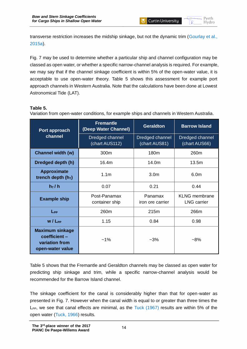
Fig. 7 may be used to determine whether a particular ship and channel configuration may be
classed as open water, or whether a specific narrow-channel analysis is required. For example,
we may say that if the channel sinkage coefficient is within 5% of the open-water value, it is
acceptable to use open-water theory. Table 5 shows this assessment for example port
approach channels in Western Australia. Note that the calculations have been done at Lowest
Astronomical Tide (LAT).
Table 5.
Variation from open-water conditions, for example ships and channels in Western Australia.
Port approach
channel
Fremantle
(Deep Water Channel) Geraldton Barrow Island
Dredged channel
(chart AUS112)
Dredged channel
(chart AUS81)
Dredged channel
(chart AUS66)
Channel width (w) 300m 180m 260m
Dredged depth (h) 16.4m 14.0m 13.5m
Approximate
trench depth (hT) 1.1m 3.0m 6.0m
hT / h 0.07 0.21 0.44
Example ship Post-Panamax
container ship
Panamax
iron ore carrier
KLNG membrane
LNG carrier
LPP 260m 215m 266m
w / LPP 1.15 0.84 0.98
Maximum sinkage
coefficient –
variation from
open-water value
~1% ~3% ~8%
Table 5 shows that the Fremantle and Geraldton channels may be classed as open water for
predicting ship sinkage and trim, while a specific narrow-channel analysis would be
recommended for the Barrow Island channel.
The sinkage coefficient for the canal is considerably higher than that for open-water as
presented in Fig. 7. However when the canal width is equal to or greater than three times the
LPP, we see that canal effects are minimal, as the Tuck (1967) results are within 5% of the
open water (Tuck, 1966) results.

Bow and Stern Sinkage Coefficients for Cargo Ships in Shallow Open Water
The 3rd-place winner of the 2017 PIANC De Paepe-Willems Award
15
5. Conclusions
For under-keel clearance management, sinkage coefficients have been developed for use in
open waterways or dredged channels. The ships considered here for calculating the sinkage
coefficients are of a broad range of ships: the DTC, KCS, JUMBO, MEGA-JUMBO, FHR Ship
D, and FHR Ship F for container ships; the KVLCC1 and KVLCC2 for oil tankers; the Japan
1704B, JBC, and FHR Ship G for bulk carriers; and the KLNG for membrane LNG carriers.
The following conclusions are drawn from the study:
The sinkage coefficient in open water varies from ship hull to ship hull, but
distinguishing characteristics depending on ship type are observed
Guidelines are suggested corresponding with three categories: container ships; oil
tankers/bulk carriers; and LNG carriers
Changes in outer water depth, or trench depth, of dredged channels substantially affect
ship sinkage
Blockage effects on the ships are found to be significant in canals
Acknowledgements
The authors would like to acknowledge:
Dr Evert Lataire and Prof. Marc Vantorre from Ghent University, and Dr Guillaume
Delefortrie from Flanders Hydraulics Research, for providing hull information for the FHR
Ships D, F, and G
Dr Klemens Uliczka from BAW Hamburg, for providing hull information for the JUMBO and
MEGA-JUMBO ships
Dr Suak Ho Van from KRISO, for providing hull information for the KLNG ship
References
Beck, R.F., Newman, J.N., and Tuck, E.O. (1975): “Hydrodynamic forces on ships in dredged
channels”, Journal of Ship Research, 19(3), p.166–171.
El Moctar, O., Shigunov, V., and Zorn, T. (2012): “Duisburg Test Case: Post-panamax container
ship for benchmarking”, Ship Technology Research Schiffstechnik, 59(3), p.50-64.
Gourlay, T.P. (1999): “The effect of squat on steady nonlinear hydraulic flow past a ship in a
channel”, Ship Technology Research Schiffstechnik, 46(4), p.217-222.
Gourlay, T.P. (2006): “Flow beneath a ship at small under keel clearance”, Journal of Ship
Research, 50(3), p.250-258.
Bow and Stern Sinkage Coefficients for Cargo Ships in Shallow Open Water
The 3rd-place winner of the 2017 PIANC De Paepe-Willems Award
16
Gourlay, T.P. (2008a): “Dynamic draught of container ships in shallow water”, International
Journal of Maritime Engineering, 150(A4), p.43-56.
Gourlay, T.P. (2008b): “Validation of KeelClear software in Torres Strait”, CMST Report 2008-
05.
Gourlay, T.P. (2013): “Ship squat in non-uniform water depth”, In: Proceedings of the Coasts
& Ports 2013 Conference, Manly, Australia.
Gourlay, T.P. (2014): “ShallowFlow: a program to model ship hydrodynamics in shallow water”,
In: Proceedings of the ASME 33rd International Conference on Ocean, Offshore and Arctic
Engineering, OMAE 2014, San Francisco, California, USA.
Gourlay, T.P., Ha, J.H., Mucha, P., and Uliczka, K. (2015a): “Sinkage and trim of modern
container ships in shallow water”, In: Proceedings of the Coasts & Ports 2015 Conference,
Auckland, New Zealand.
Gourlay, T.P. and Klaka, K. (2007): “Full-scale measurements of containership sinkage, trim
and roll”, Australian Naval Architect, 11(2), p.30–36.
Gourlay, T.P., Lataire, E., and Delefortrie, G. (2016): “Application of potential flow theory to
ship squat in different canal widths”, In: Proceedings of the 4th International Conference on
Ship Manoeuvring in Shallow and Confined Water, MASHCON 2016, Hamburg, Germany.
Gourlay, T.P., von Graefe, A., Shigunov, V., and Lataire, E. (2015b): “Comparison of AQWA,
GL RANKINE, MOSES, OCTOPUS, PDSTRIP and WAMIT with model test results for cargo
ship wave-induced motions in shallow water”, In: Proceedings of the ASME 34th International
Conference on Ocean, Offshore and Arctic Engineering, OMAE 2015, St. John's,
Newfoundland, Canada.
Graff, W., Kracht, A., and Weinblum, G. (1964): “Some extensions of D. W. Taylor’s standard
series”, Transactions of the Society of Naval Architects and Marine Engineers, 72, p.374-401.
Ha, J.H., Gourlay, T.P., and Nadarajah, N. (2016): “Measured ship motions in Port of Geraldton
approach channel”, In: Proceedings of the 4th International Conference on Ship Manoeuvring
in Shallow and Confined Water, MASHCON 2016, Hamburg, Germany.
Hooft, J.P. (1974): “The behaviour of a ship in head waves at restricted water depth”,
International Shipbuilding Progress, 244(21), 367.
Huuska, O. (1976): “On the evaluation of underkeel clearances in Finnish waterways”, Helsinki
University of Technology, Ship Hydrodynamics Laboratory, Otaniemi, Report No. 9.
ICORELS (International Commission for the Reception of Large Ships) (1980): “Report of
Working Group IV”, PIANC Bulletin No. 35, Supplement.
Jachowski, J. (2008): “Assessment of ship squat in shallow water using CFD”, Archives of
Civil and Mechanical Engineering, 8(1), p.27-36.
Bow and Stern Sinkage Coefficients for Cargo Ships in Shallow Open Water
The 3rd-place winner of the 2017 PIANC De Paepe-Willems Award
17
Larsson, L., Stern, F., and Bertram, V. (2003): “Benchmarking of computational fluid dynamics
for ship flows: The Gothenburg 2000 Workshop”, Journal of Ship Research, 47(1), p.63-81.
Lee, S.J., Koh, M.S., and Lee, C.M. (2003): “PIV velocity field measurements of flow around
a KRISO 3600TEU container ship model”, Journal of Marine Science and Technology, 8(2),
p.76-87.
Millward, A. (1992): “A comparison of the theoretical and empirical prediction of squat in
shallow water”, International Shipbuilding Progress, 39(417), p.69-78.
Mucha, P., el Moctar, O., and Böttner, U.C. (2014): “Technical note: PreSquat - Workshop on
numerical prediction of ship squat in restricted waters”, Ship Technology Research
Schiffstechnik, 61(3), p.162-165.
Nautical Institute (2015): “Navigation Accidents and their Causes”, The Nautical Institute
Publications.
NMRI (2015): Tokyo 2015, “A Workshop on CFD in Ship Hydrodynamics”, [Online], Available:
http://www.t2015.nmri.go.jp
PIANC (2014): “Harbour Approach Channels Design Guidelines”, PIANC Report No. 121.
Tuck, E.O. (1966): “Shallow water flows past slender bodies”, Journal of Fluid Mechanics, 26,
p.81-95.
Tuck, E.O. (1967): “Sinkage and trim in shallow water of finite width”, Schiffstechnik, 14, p.92-
94.
Uliczka, K., Kondziella, B., and Flügge, G. (2004): “Dynamisches fahrverhalten sehr großer
containerschiffe in seitlich begrenztem extremen Flachwasser”, HANSA, 141.
Van, S.H., Kim, W.J., Yoon, H.S., Lee, Y.Y., and Park, I.R. (2006): “Flow measurement around
a model ship with propeller and rudder”, Experiments in Fluids, 40(4), p.533-545.
Van, S.H., Kim, W.J., Yim, D.H., Kim, G.T., Lee, C.J., and Eom, J.Y. (1998): “Flow
measurement around a 300K VLCC model”, In: Proceedings of the Annual Spring Meeting,
The Society of Naval Architects of Korea (SNAK), Ulsan, Korea, p.185-188.
Van, S.H., Yoon, H.S., Lee, Y.Y., Park, I.R., Lee, C.J., and Kim, W.J. (2003): “Measurement of
flow around KRISO 138K LNG carrier model”, Journal of the Society of Naval Architects of
Korea, 40(2), p.1-10.
Vantorre, M. (2003): “Review of practical methods for assessing shallow and restricted water
effects”, In: International Conference on Marine Simulation and Ship Manoeuvrability,
MARSIM 2003, Kanazawa, Japan, WS-4-1-WS-4-11.
Vantorre, M. and Journée, J.M.J. (2003): “Validation of the strip theory code SEAWAY by
model tests in very shallow water”, In: Numerical Modelling Colloquium, Flanders Hydraulics
Research, Antwerp, Belgium, DUT-SHL Report Nr. 1373-E.

Bow and Stern Sinkage Coefficients for Cargo Ships in Shallow Open Water
The 3rd-place winner of the 2017 PIANC De Paepe-Willems Award
18
von Graefe, A. (2014): “A Rankine source method for ship-ship interaction and shallow water
problems”, University of Duisburg-Essen, Ph.D. Thesis.
Yokoo, K. (1966): “Systematic series model tests in Japan concerning the propulsive
performance of full ship forms”, Japan Shipbuilding and Marine Engineering, 1(2), p.13–22.
About the author
Jeong Hun Ha is a Ph.D. candidate at the Centre for Marine Science
and Technology (CMST) at Curtin University, Australia. His Ph.D.
thesis is about ship under-keel clearance in port approach channels.
His background is as a Korean civil engineer in the design of port and
coastal structures.
Tim Gourlay is Director of Perth Hydro Pty Ltd and supervising Jeong
Hun Ha’s Ph.D. thesis. He undertakes research and consulting work
in ship under-keel clearance for ports in Australia and internationally.
He is the author of ShallowFlow and SlenderFlow software, and has
conducted full-scale ship motion measurements on 60 cargo ship
transits through navigation channels.