boundary element analysis of mixed-mode stress...
TRANSCRIPT
EC26,8
1056
Engineering Computations:International Journal for Computer-Aided Engineering and SoftwareVol. 26 No. 8, 2009pp. 1056-1073# Emerald Group Publishing Limited0264-4401DOI 10.1108/02644400910996899
Received 14 April 2008Revised 17 September 2008Accepted 13 March 2009
Boundary element analysis ofmixed-mode stress intensity
factors in an anisotropic cuboidwith an inclined surface crack
Chia-Hau Chen and Chao-Shi ChenDepartment of Resources Engineering, National Cheng Kung University,
Tainan, Taiwan
Ernian PanDepartment of Civil Engineering, University of Akron, Akron, Ohio, USA
Han-Chou TsengDepartment of Resources Engineering, National Cheng Kung University,
Tainan, Taiwan, and
Pao-Shan YuDepartment of Hydraulic and Ocean Engineering,National Cheng Kung University, Tainan, Taiwan
Abstract
Purpose – The purpose of this paper is to present special nine-node quadrilateral elements to discretizethe un-cracked boundary and the inclined surface crack in a transversely isotropic cuboid under auniform vertical traction along its top and bottom surfaces by a three-dimensional (3D) boundary elementmethod (BEM) formulation. The mixed-mode stress intensity factors (SIFs),KI, KII and KIII, are calculated.Design/methodology/approach – A 3D dual-BEM or single-domain BEM is employed to solve thefracture problems in a linear anisotropic elastic cuboid. The transversely isotropic plane has anarbitrary orientation, and the crack surface is along an inclined plane. The mixed 3D SIFs are evaluatedby using the asymptotical relation between the SIFs and the relative crack opening displacements.Findings – Numerical results show clearly the influence of the material and crack orientations on themixed-mode SIFs. For comparison, the mode-I SIF when a horizontal rectangular crack is embeddedentirely within the cuboid is calculated also. It is observed that the SIF values along the crack frontare larger when the crack is closer to the surface of the cuboid than those when the crack is far awayfrom the surface.Research limitations/implications – The FORTRAN program developed is limited to regularsurface cracks which can be discretized by the quadrilateral shape function; it is not very efficient andsuitable for irregular crack shapes.Practical implications – The evaluation of the 3D mixed-mode SIFs in the transversely isotropicmaterial may have direct practical applications. The SIFs have been used in engineering design toobtain the safety factor of the elastic structures.Originality/value – This is the first time that the special nine-node quadrilateral shape function hasbeen applied to the boundary containing the crack mouth. The numerical method developed can beapplied to the SIF calculation in a finite transversely isotropic cuboid within an inclined surfacecrack. The computational approach and the results of SIFs are of great value for the modeling anddesign of anisotropic elastic structures.
Keywords Surface properties of materials, Stress (materials), Physical properties of materials,Elastic analysis
Paper type Research paper
The current issue and full text archive of this journal is available atwww.emeraldinsight.com/0264-4401.htm
The project is sponsored by NCKU under grant number R046. The authors thank the reviewersand Editor for their beneficial comments and suggestions.
Mixed-modestress intensity
factors
1057
1. IntroductionDefects are commonly originated from the free surface. They are inherent to thestructural materials or are developed during manufacturing and fabrication. Thus,study of surface cracks is fundamental to fracture analysis of the involved structure.Regardless of how a surface crack is initiated or introduced in a component, accurateprediction of the fracture conditions (i.e. mixed-mode stress intensity factors (SIFs)) isvery important in solid mechanics. There are three basic modes of crack tipdeformation in the fracture process: mode-I (tension, opening), mode-II (in-plane shear,sliding) and mode-III (out-of-plane shear, tearing). The fracture mechanical safety of asolid elastic structure can be designed depended on these SIFs (Toribio and Kharin,1997). Therefore, evaluation of SIFs along the crack front in linear elastic fracturemechanics has been considerably investigated. However, accurate calculation of SIFsfor three-dimensional (3D) crack surface is still an important computational issue infracture mechanics.
Irwin first introduced the SIFs to describe the stress and displacement fields near acrack tip in 1957 (Irwin, 1957), and obtained an approximate solution for the cracksurface problem in 1962 (Irwin, 1962). Literature associated with this problem is quiteextensive and various numerical techniques have been proposed to obtain 3D SIFs infracture problems. Mi and Aliabadi (1992) presented the 3D dual boundary elementmethod (dual-BEM) for linear elastic crack problems, and used it to overcome thenumerical difficulties associated with the two mathematically identical sides of a crack.Singh et al. (1998) obtained the SIFs using the concept of a universal crack closureintegral in 3D isotropic elastic materials. Pan and Yuan (2000) applied the especial nine-node elements to discretize the un-cracked boundary and the crack surface in aninfinite space or a finite cube, and also derived the relation between SIFs and therelative crack opening displacements (CODs) technique. Lazarus et al. (2001) comparedthe mixed-mode I-II or I-II-III SIFs between the theoretical analyses and theexperimental results in the brittle solid considering the crack front rotation orsegmentation. A new 3D variable-order singular boundary element was presented byZhou et al. (2005). These elements can be used for both straight and curved crack frontsin the embedded penny-shaped homogeneous and bi-material interface crack problems.Leung and Su (1995) used the finite element methods (FEM) to investigate the stressdistribution and the variation of the mode-I SIF near the mid-plane of the specimen. Heet al. (1997) proposed a 3D COD correlation formula to calculate SIFs in 3D fractureproblems by using FEM in which the 20-node collapsed iso-parametric quarter-pointelements were adopted. Ayatollahi and Hashemi (2007) carried out a 3D finite elementanalysis to investigate the effect of asymmetric composite reinforcement on the cracktip parameters KI, KII and T-stress. Yue et al. (2007) employed the dual-BEM in theircalculation of the 3D SIFs of an inclined square crack within a bi-material cuboid.
In recent years, BEM provides a powerful alternative to FEM particularly in theanalysis of 3D fracture problems where better accuracy are required such as damagedmaterial (Hatzigeorgiou and Beskos, 2002); dynamic material (Ariza and Dominguez,2004); bi-material (Noda et al., 2006; Qin et al., 2008); thermo-elastic material (dell’Erbaand Aliabadi, 2000); magneto-electro-elastic material (Zhao et al., 2007); non-linearsurface crack (Liu et al., 1999); multiple-crack (Lo et al., 2005; Popov et al., 2003); crackgrowth (Blackburn, 1999); or where the physical domain extends to infinity (Pan andYuan, 2000). The most important feature of BEM is that it requires only 2D meshing ofthe 3D crack surface and the un-crack boundary. BEM is based on the boundaryintegral equations of displacement and traction, which both being evaluated directly on

EC26,8
1058
the boundary. Hence, boundary element codes can be very conveniently used withexisting solid modelers and surface mesh generators. This advantage is particularlyimportant for design as the process usually involves a series of modifications, whichare more difficult to carry out using FEM. In BEM, the usage of quadrilateralcollocation shape functions is a popular method as adopted by many scholars (Arizaet al., 1997; Partheymuller et al., 2000; Ong and Lim, 2005; Mezrhab and Bouzidi, 2005;Guzina et al., 2006).
In this paper, we present the special nine-node quadrilateral collocation shapefunctions to descretize (or approximate) the surface crack on the partial boundary. Acombination of the dual-BEM (or single-domain BEM) and the relative COD isemployed to analyze the mixed 3D SIFs in a transversely isotropic cuboid with anyoriented isotropic plane and varying crack plane orientation. Numerical results on theedge crack case show that material and crack orientations can significantly influencethe mixed SIFs along the front of the edge crack. Our results on the embedded crackcase show that when one of the crack fronts moves to the boundary of the cuboid, thecorresponding mixed SIFs can be significantly increased.
2. Global and local coordinate system relationsIn the present paper, a 3D boundary element analysis is carried out to obtain mode-I,mode-II and mode-III SIFs along the crack front of a rectangular surface crack in acuboid subjected to a tension loading �0 (Figure 1). The orientation between thematerial and crack are described respectively by the relation between the global (x, y, z)and local material (x0, y0, z0), and between the global (x, y, z) and local crack (x00, y00, z00)coordinate systems. The surface crack is on the (x00-y00) plane with its normal being the
Figure 1.An edge rectangularcrack (2a � a) within afinite cuboid (w � t � h)under a uniform normalstress �0 along thez-direction
Mixed-modestress intensity
factors
1059
z00-axis, and is located inside a transversely isotropic elastic finite domain witharbitrarily oriented transverse isotropy. In the material coordinate, the local z0-axis isalong the symmetry axis of the transversely isotropic material, and the local (x0-y0)plane is parallel to the isotropic plane of the material. The inclined angle is defined asthe angle between the global horizontal plane (x-y) and the material isotropic (x0-y0)plane. � is the dip orientation between the y-axis and the inclined plane. In the cracksurface, the crack angle � is defined as the angle between the global horizontal (x-y)plane and the crack surface (x00-y00) plane.
It is obvious that the transformations between the local material (x0, y0, z0) and global(x, y, z) coordinates and between the local crack (x00, y00, z00) and global (x, y, z) can bedescribed by the following relations:
x0
y0
z0
264
375 ¼
cos� �sin � 0
cos sin � cos cos � �sin
sin sin� sin cos � cos
264
375
x
y
z
264
375 ð1Þ
x00
y00 þ 0:5a
z00
264
375 ¼
1 0 0
0 cos � sin �
0 �sin � cos �
264
375
x
yþ 0:5t
z
264
375 ð2Þ
where a is the width of the surface crack along y00-axis; t is the width of the cuboidalong y-axis.
3. Boundary integral equationsThe displacement and traction boundary integral equations for solving 3D linearelastic fracture problems with cracks are based on the dual-BEM (Aliabadi, 1997) or thesingle-domain BEM (Pan, 1997) approach. We assume that the finite domain underconsideration is bounded by an outer boundary S with given boundary conditions.Inside there is a crack described by its surface � (where � ¼ �þ ¼ ���, withsuperscripts ‘‘þ’’ and ‘‘�’’ denoting the positive and negative sides of the crack). Wefurther assume that the tractions on both sides of the crack are equal and opposite.Then the single-domain BEM formulation consists of the following displacement andtraction boundary integral equations (Pan and Amadei, 1996a):
cijðySÞujðySÞ þðS
ujðxSÞT�ijðyS;xSÞ � tjðxSÞU �
ij ðyS;xSÞh i
dSðxSÞ
¼ �ð�
�ujðx�ÞT�ijðyS;x�þÞ
h id�ðx�þÞ ð3Þ
0:5�Tlðy�Þ þ nmðy�þÞðS
clmikT�ij;kðy�þ ;xSÞujðxSÞdSðxSÞ
þ nmðy�þÞð�
�ujðx�ÞclmikT�ij;kðy�þ ;x�þÞ
h id�ðx�þÞ
¼ nmðy�þÞðS
clmikU�ij;kðy�þ ;xSÞTjðxSÞdSðxSÞ ð4Þ
where cij are coefficients that depend only upon the local geometry of the uncrackedboundary at yS. A point on the positive (or negative) side of the crack is denoted by x�þ
EC26,8
1060
(or x�� ), and on the uncracked boundary by both xS and yS. Also in Equation (3),uj and tj represent the displacements and tractions on the boundary (or crack surface),and U �
ij and T�ij are the Green’s functions for displacements and tractions in
general anisotropic elastic solid (Pan and Yuan, 2000). nm is the unit outward normalof the positive side of the crack surface at y�þ and clmik is the fourth-order stiffnesstensor of the anisotropic medium; U �
ij;k and T�ij;k are, respectively, the derivatives of the
Green’s displacements and tractions with respect to the source point (Pan and Amadei,1996b).
The strong singularity of T�ij on the left-hand side of Equation (3) can be avoided
by the rigid-body motion method. At the same time, the calculation of cij can also beavoided. The second integral term on the left-hand side has only a weak singularity,and is integrable. Equations (3) and (4) form a pair of boundary integral equations,called single-domain BEMs, and they can be applied to generally anisotropic media.They can be discretized and solved numerically for the unknown boundarydisplacements (or the relative CODs on the crack surface) and tractions. However,before we apply these single-domain BEMs to calculate the mixed SIFs, we first brieflypresent the special elements and the technique for evaluating the 3D SIF.
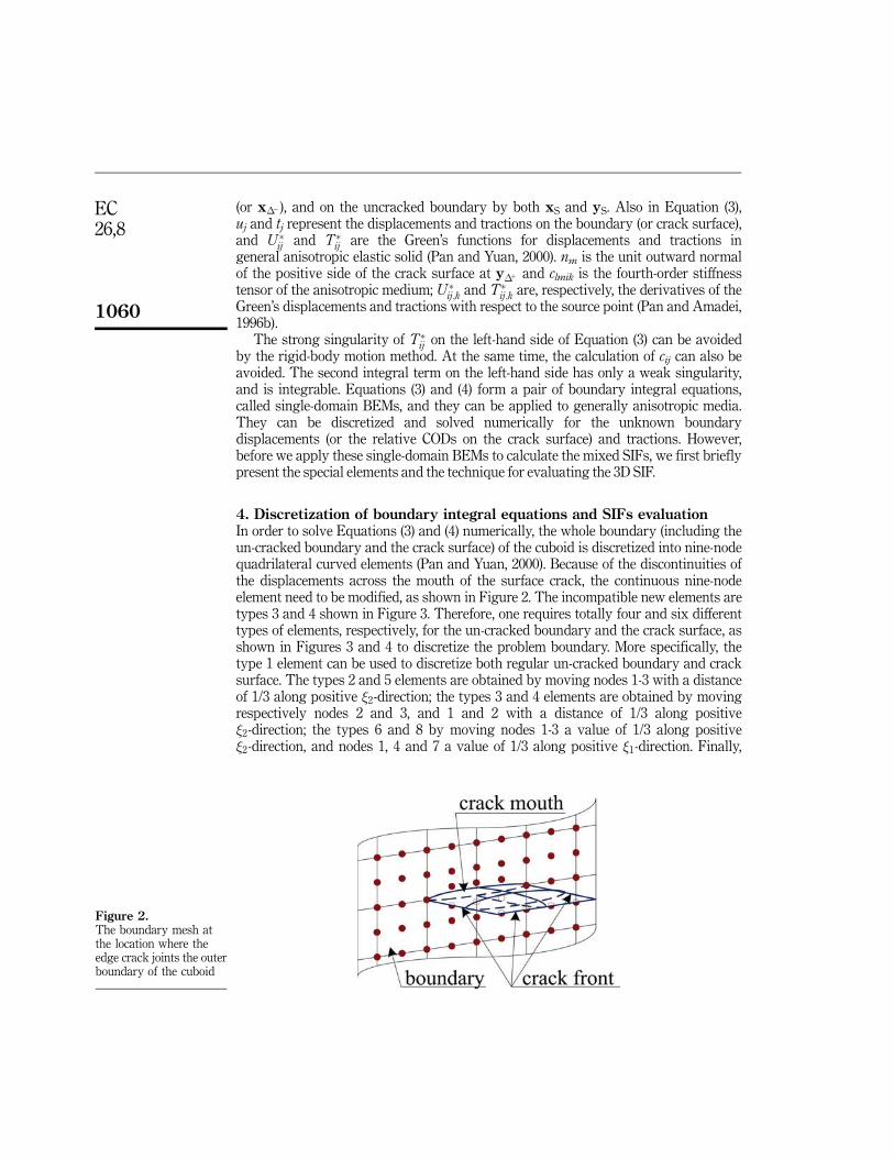
4. Discretization of boundary integral equations and SIFs evaluationIn order to solve Equations (3) and (4) numerically, the whole boundary (including theun-cracked boundary and the crack surface) of the cuboid is discretized into nine-nodequadrilateral curved elements (Pan and Yuan, 2000). Because of the discontinuities ofthe displacements across the mouth of the surface crack, the continuous nine-nodeelement need to be modified, as shown in Figure 2. The incompatible new elements aretypes 3 and 4 shown in Figure 3. Therefore, one requires totally four and six differenttypes of elements, respectively, for the un-cracked boundary and the crack surface, asshown in Figures 3 and 4 to discretize the problem boundary. More specifically, thetype 1 element can be used to discretize both regular un-cracked boundary and cracksurface. The types 2 and 5 elements are obtained by moving nodes 1-3 with a distanceof 1/3 along positive �2-direction; the types 3 and 4 elements are obtained by movingrespectively nodes 2 and 3, and 1 and 2 with a distance of 1/3 along positive�2-direction; the types 6 and 8 by moving nodes 1-3 a value of 1/3 along positive�2-direction, and nodes 1, 4 and 7 a value of 1/3 along positive �1-direction. Finally,
Figure 2.The boundary mesh atthe location where theedge crack joints the outerboundary of the cuboid

Mixed-modestress intensity
factors
1061
types 7 and 9 are obtained by moving nodes 1-3 a value of 1/3 along positive�2-direction and nodes 3, 6, 9 a value of 1/3 along negative �1-direction.
The global coordinates (xi), displacements (ui) and tractions (ti) at any point withinone element on the un-cracked boundary can be expressed as:
xið�Þ ¼X9j¼1
�jð�Þxji; uið�Þ ¼X9j¼1
�jð�Þ uji; tið�Þ ¼X9j¼1
�jð�Þ tji ; i ¼ 1; 2; 3 ð5Þ
where the subscript i denotes the component of nodal coordinates and the superscript jdenotes the number of nodes. The shape functions �j ( j ¼ 1-9) are functions of theintrinsic coordinates (�1, �2), and their expressions for different elements are listed inthe Appendix.
Similarly, the relative CODs �ui (�ui ¼ u�þi � u��i ) on the crack surface can beapproximated as:
�ui ¼X9j¼1
�j �uji; i ¼ 1; 2; 3 ð6Þ
Figure 3.Four different types of
elements for un-crackedboundaries

EC26,8
1062
However, for the relative CODs on the crack element near a crack front, the crack shapefunctions are multiplied by suitable weight functions for accurate evaluation of the SIFs.It is well-known that for a crack in a homogeneous and anisotropic solid, the relativeCODs are proportional to
ffiffiffir
p, where r is the distance behind the crack tip (front).
Therefore, for element types 5-7 (Figure 4), we employ the following approximation forthe relative CODs:
Figure 4.Six different types ofelements for the cracksurface

Mixed-modestress intensity
factors
1063
�ui ¼X9j¼1
ffiffiffiffiffiffiffiffiffiffiffiffiffiffiffiffið1þ �2Þ
p�j�uji; i ¼ 1; 2; 3 ð7Þ
where �j are again the shape functions given in the Appendix.In addition, we use the following two approximations for element types 8 and 9,
respectively:
�ui ¼X9j¼1
ffiffiffiffiffiffiffiffiffiffiffiffiffiffiffiffiffiffiffiffiffiffiffiffiffiffiffiffiffiffiffiffið1þ �1Þð1þ �2Þ
p�j�uji; i ¼ 1; 2; 3 ð8Þ
�ui ¼X9j¼1
ffiffiffiffiffiffiffiffiffiffiffiffiffiffiffiffiffiffiffiffiffiffiffiffiffiffiffiffiffiffiffiffið1� �1Þð1þ �2Þ
p�j�uji; i ¼ 1; 2; 3 ð9Þ
Once the relative CODs are solved in the global coordinates, they can be transformedto the local coordinates (or the crack tip coordinates) to find the SIFs. Assuming thatthe crack front is smooth and that the crack tip is away from the corner, then theasymptotic expansion of the relative COD field near the crack tip (front) satisfiesthe generalized plane strain condition in the local coordinates. Actually, if we let r bethe distance behind the crack front, then in terms of the relative CODs in the crack-tipcoordinate, the three SIFs can be expressed as follows:
KII
KI
KIII
8<:
9=; ¼ 2
ffiffiffiffiffi2r
�
rL�1
�u1�u2�u3
8<:
9=; ð10Þ
where L is the Barnett-Lothe tensors (Ting, 1996) which depends only on theanisotropic properties of the solid in the crack front coordinates. The normalized SIFs(FI, FII and FIII) can be calculated as follows:
FI
FII
FIII
8<:
9=; ¼ ��1
0
ffiffiffiffiffiffi1
�a
r KI
KII
KIII
8<:
9=; ð11Þ
where �0 is the applied vertical traction in the problem to be discussed below.
5. Numerical results and discussionConsider a linearly elastic, homogeneous, and transversely isotropic cuboid withdimension w � t � h, as shown in Figure 1. Let x, y and z be the global Cartesiancoordinates with their origin in the center of the cuboid. A rectangular surface crack of2a � a is located in the cuboid with one of its sides along the edge of the cuboid. A localcoordinate system (x00, y00, z00) is attached to the crack with its z00-axis normal to thecrack surface. The angle of crack orientation � is defined as the angle between theglobal horizontal (x-y) plane and the crack (x00-y00) plane.
The cracked finite cuboid is under a uniform normal tensile stress �0 applied at thetop and bottom faces, as shown in Figure 1. In the numerical example, the cuboid size ischosen to be w/t ¼ 2, h/t ¼ 4 and the size of rectangular crack 2a/t ¼ 1. The materialof the cuboid is a transversely isotropic marble and its elastic properties were obtained
EC26,8
1064
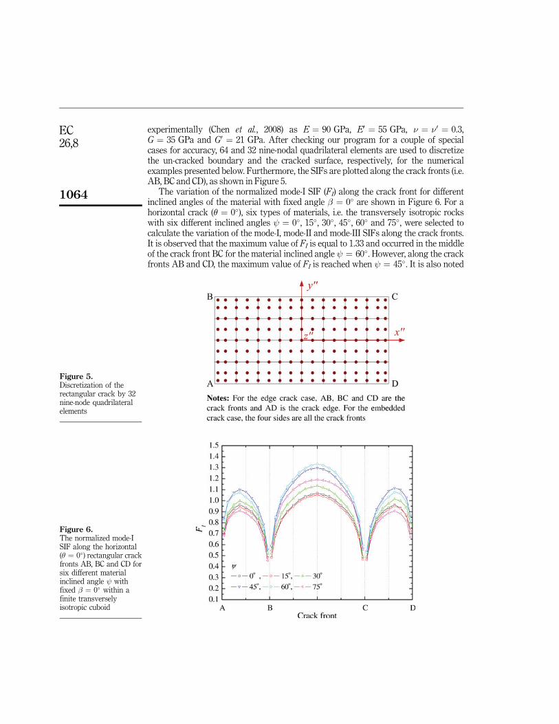
experimentally (Chen et al., 2008) as E ¼ 90 GPa, E0 ¼ 55 GPa, � ¼ �0 ¼ 0.3,G ¼ 35 GPa and G0 ¼ 21 GPa. After checking our program for a couple of specialcases for accuracy, 64 and 32 nine-nodal quadrilateral elements are used to discretizethe un-cracked boundary and the cracked surface, respectively, for the numericalexamples presented below. Furthermore, the SIFs are plotted along the crack fronts (i.e.AB, BC and CD), as shown in Figure 5.
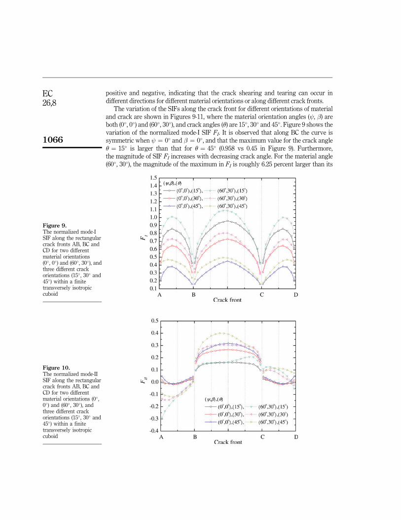
The variation of the normalized mode-I SIF (FI) along the crack front for differentinclined angles of the material with fixed angle � ¼ 0� are shown in Figure 6. For ahorizontal crack (� ¼ 0�), six types of materials, i.e. the transversely isotropic rockswith six different inclined angles ¼ 0�, 15�, 30�, 45�, 60� and 75�, were selected tocalculate the variation of the mode-I, mode-II and mode-III SIFs along the crack fronts.It is observed that the maximum value of FI is equal to 1.33 and occurred in the middleof the crack front BC for the material inclined angle ¼ 60�. However, along the crackfronts AB and CD, the maximum value of FI is reached when ¼ 45�. It is also noted
Figure 5.Discretization of therectangular crack by 32nine-node quadrilateralelements
Figure 6.The normalized mode-ISIF along the horizontal(� ¼ 0�) rectangular crackfronts AB, BC and CD forsix different materialinclined angle withfixed � ¼ 0� within afinite transverselyisotropic cuboid

Mixed-modestress intensity
factors
1065
that the SIF FI is symmetric along the crack fronts AB and CD only when ¼ 0�. It isalso interesting that since the material dip angle � ¼ 0� and crack angle � ¼ 0�, theSIF FI is symmetric with respect to the middle point of the crack front BC, and that theSIF FI along AB is the same as that along DC. Furthermore, the magnitude of FI alongBC is, in general, larger than that along AB or CD for a given material angle .
Figures 7 and 8 show, respectively, the variation of the normalized mode-II SIF (FII)and mode-III (FIII) along the crack fronts AB, BC and CD for different material angle (� ¼ 0�) with fixed angle orientation (� ¼ 0�). Compared to Figure 6, we observed thatthe magnitude of the SIF for mode II and III is much smaller than that for mode-I.We also noted from Figures 7 and 8 that the SIF value for mode II and III can be both
Figure 7.The normalized mode-IISIF along the horizontal
(� ¼ 0�) rectangular crackfronts AB, BC and CD for
six different materialinclined angle withfixed � ¼ 0� within a
finite transverselyisotropic cuboid
Figure 8.The normalized mode-IIISIF along the horizontal
(� ¼ 0�) rectangular crackfronts AB, BC and CD for
six different materialinclined angle withfixed � ¼ 0� within a
finite transverselyisotropic cuboid
EC26,8
1066
positive and negative, indicating that the crack shearing and tearing can occur indifferent directions for different material orientations or along different crack fronts.
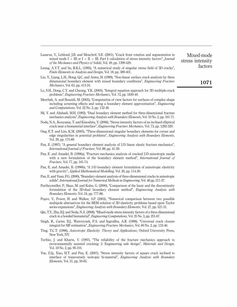
The variation of the SIFs along the crack front for different orientations of materialand crack are shown in Figures 9-11, where the material orientation angles ( , �) areboth (0�, 0�) and (60�, 30�), and crack angles (�) are 15�, 30� and 45�. Figure 9 shows thevariation of the normalized mode-I SIF FI. It is observed that along BC the curve issymmetric when ¼ 0� and � ¼ 0�, and that the maximum value for the crack angle� ¼ 15� is larger than that for � ¼ 45� (0.958 vs 0.45 in Figure 9). Furthermore,the magnitude of SIF FI increases with decreasing crack angle. For the material angle(60�, 30�), the magnitude of the maximum in FI is roughly 6.25 percent larger than its
Figure 9.The normalized mode-ISIF along the rectangularcrack fronts AB, BC andCD for two differentmaterial orientations(0�, 0�) and (60�, 30�), andthree different crackorientations (15� , 30� and45�) within a finitetransversely isotropiccuboid
Figure 10.The normalized mode-IISIF along the rectangularcrack fronts AB, BC andCD for two differentmaterial orientations (0�,0�) and (60�, 30�), andthree different crackorientations (15�, 30� and45�) within a finitetransversely isotropiccuboid

Mixed-modestress intensity
factors
1067
value at the center of BC, due to the effects of inclined angle and dip angle. Themaximum value for the crack angle � ¼ 15� is larger than that � ¼ 45� (1.09 vs 0.49 inFigure 9). It is noted that the magnitude of FI along AB and CD is roughly the same asthat along BC. As for the mode-II and mode-III, we observed from Figures 10 and 11that the SIF variation for the shearing and tearing modes FII and FIII is muchcomplicated than that of FI. Similar to Figures 7 and 8 for � ¼ 0� and � ¼ 0�, shearingand tearing in different directions can be observed along different crack fronts.
We study the effect of the crack distance (to the free edge of the cuboid) on the SIFs.Different distance ratios d/t (¼0, 0.05, 0.1, 0.15, 0.2 and 0.25) are selected, whilst thecrack size is kept constant, as shown in Figure 12. The material angles are also fixed at ¼ �¼ 0�. The results of the mode-I SIF FI for the edge crack (i.e. d/t ¼ 0) as well asthe embedded crack (i.e. d/t ¼ 0.05, 0.1, 0.15, 0.2 and 0.25) are plotted in Figure 13. It isnoted that when d/t ¼ 0 the crack front DA becomes the crack mouth. Our numericalresults show that the FI value increases with decreasing distance d/t, and that theresults along the crack front AB are the same as that along CD due to the symmetry ofthe problem. It is interesting to observe that the maximum SIF along DA is larger thanthat along BC (1.17 vs 1.07). This phenomenon is due to the fact that the crack front
Figure 11.The normalized mode-IIISIF along the rectangularcrack fronts AB, BC and
CD for two differentmaterial orientations
(0�, 0�) and (60�, 30�), andthree different crack
orientations (15�, 30� and45�) within a finite
transversely isotropiccuboid
Figure 12.An embedded horizontalrectangular crack locatedon the z ¼ 0 plane of afinite cuboid. The crackfront AD intercepts theouter boundary of thecuboid when the crackmoves to the surfacealong the negative
y-direction

EC26,8
1068
along DA is closer to the edge of cuboid than the front BC. When the crack is located inthe center of cuboid (d/t ¼ 0.25), the SIF variation becomes the same along the crackfronts BC and DA. The maximum SIF values along different crack fronts for differentdistance d/t are presented in Table I in order to show quantitatively those the effect ofthe crack distance on the SIFs.
Finally, we also study the interactive effect of two edged cracks on SIFs, as shown inFigure 14. The relative distance ratio L/t (¼0.3, 0.5 and 0.7) are selected to discuss thevariation of the normalized mode-I, mode-II and mode-III SIFs along the crack front BC.For two horizontal cracks (� ¼ 0�), the results of the normalized SIFs with the sevendifferent material inclined angle ¼ 0� to 90� (� is fixed at 30�) are plotted inFigure 15. It is observed that the maximum value of FI is equal to 1.64 and occurred inthe L/t ¼ 0.3 for the material inclined angle ¼ 45�. However, the magnitude of SIFFI decreases with increasing distance ratio L/t. It is noted that the interactive effect oftwo edged rectangular cracks is changed with respect to both the distance ratio andmaterial angle. For the mode-II and mode-III SIFs, we observed from Figure 15 that themagnitudes of FI and FII along crack front BC are large variation when ¼ 45�. Whenthe material angle is fixed at ¼ �¼ 0�, the maximum normalized mode-I SIF valuesalong the crack fronts AB, BC and CD are presented in Table II. The result shows thatthe values of SIF FI decreases with increasing distance ratio L/t (0.3 to 0.8) in order tosignify the interactive effect of the relative crack distance on the SIFs.
Figure 13.Normalized mode-I SIFalong the crack fronts AB,BC, CD and DA fordifferent crack distance(to the boundary of thecuboid) d/t from 0 to 0.25
Table I.Maximum normalizedmode-I SIF along thecrack fronts AB, BC, CDand DA of therectangular crack fordifferent crack distance(to the outer boundaryof the cuboid) d/t
d/tCrack front
AB BC CD DA
0 0.951 1.066 0.951 �0.05 0.896 1.067 0.896 1.1730.1 0.866 1.011 0.866 1.0800.15 0.849 0.993 0.849 1.0340.2 0.839 0.986 0.839 1.0050.25 0.836 0.990 0.836 0.990

Mixed-modestress intensity
factors
1069
Figure 14.Two edged horizontal
rectangular cracks locatedon the z ¼ 0 plane of a
finite cuboid
Figure 15.Normalized SIFs on x ¼ 0along the crack front BCfor three different crackinteractive distances L/t
and seven differentmaterial inclined angle with fixed � ¼ 30� within
a finite transverselyisotropic cuboid
Table II.Maximum normalizedmode-I SIF along the
crack fronts AB, BC andCD of two edged
rectangular cracks fordifferent relative
distance L/t
L/tCrack front
AB BC CD
0.3 1.193 1.408 1.1930.4 0.988 1.120 0.9880.5 0.862 0.959 0.8620.6 0.745 0.831 0.7450.7 0.617 0.697 0.6170.8 0.477 0.574 0.477

EC26,8
1070
6. ConclusionsIn this study, the normalized mode-I, mode-II and mode-III SIFs along the crack front ofa rectangular crack in a cuboid are calculated based on the dual-BEM or the single-domain BEM. Both the crack orientation and material orientation (including theinclined angle and dip angle) of the transversely isotropic cuboid can be varied. A set ofsix special nine-node quadrilateral elements are introduced to approximate the crackfront and the mixed 3D SIFs are evaluated using the asymptotical relation between theSIFs and the relative COD via the Barnett-Lothe tensor. Numerical examples of themixed 3D SIFs are presented for the transversely isotropic cracked cuboid under auniform vertical traction on its top and bottom surfaces. Results show that for ahorizontal edge crack, the mode-I is symmetric with respect to the middle of the crackfront when the material inclined angle ¼ 0� (� ¼ 0�); otherwise the SIF values areasymmetric. Variations of the SIFs for mode-II and mode-III along the crack fronts arecomplicated with shearing and tearing in different directions being observed. For anembedded rectangular crack, it is observed that when the crack moves away from theedge, the mode-I SIF will be reduced. For two edged rectangular cracks, the interactiveeffect on SIFs is varied with both the material orientation and relative crack distance.
References
Aliabadi, M.H. (1997), ‘‘Boundary element formulations in fracture mechanics’’, AppliedMechanics Review, Vol. 50, pp. 83-96.
Ariza, M.P. and Dominguez, J. (2004), ‘‘Dynamic BE analysis of 3-D cracks in transverselyisotropic solids’’, Computer Methods in Applied Mechanics and Engineering, Vol. 193,pp. 765-79.
Ariza, M.P., Saez, A. and Dominguez, J. (1997), ‘‘A singular element for three-dimensional fracturemechanics analysis’’, Engineering Analysis with Boundary Elements, Vol. 20, pp. 275-85.
Ayatollahi, M.R. and Hashemi, R. (2007), ‘‘Computation of stress intensity factors (KI, KII) andT-stress for cracks reinforced by composite patching’’, Composite Structure, Vol. 78,pp. 602-9.
Blackburn, W.S. (1999), ‘‘Three dimensional calculation of growth of cracks starting in parallelplanes by boundary elements’’, Internal Journal of Fatigue, Vol. 21, pp. 933-9.
Chen, C.H., Chen, C.S. and Wu, J.H. (2008), ‘‘Fracture toughness analysis on cracked ring disks ofanisotropic rock’’, Rock Mechanics and Rock Engineering., Vol. 41 No. 4, pp. 539-62.
dell’Erba, D.N. and Aliabadi, M.H. (2000), ‘‘On the solution of three-dimensional thermoelasticmixed-mode edge crack problems by the dual boundary element method’’, Engineering.Fracture Mechanics, Vol. 66, pp. 269-85.
Guzina, B.B., Pak, R.Y.S. and Martınez-Castro, A.E. (2006), ‘‘Singular boundary elements forthree-dimensional elasticity problems’’, Engineering Analysiswith Boundary Elements,Vol. 30, pp. 623-39.
Hatzigeorgiou, G.D. and Beskos, D.E. (2002), ‘‘Static analysis of 3D damaged solids and structuresby BEM’’, Engineering Analysis with Boundary Elements, Vol. 26, pp. 521-6.
He, W.J., Lin, Y. and Ding, H.J. (1997), ‘‘A three-dimensional formula for determining stressintensity factors in finite element analysis of cracked bodies’’, Engineering FractureMechanics, Vol. 57 No. 4, pp. 409-15.
Irwin, G.R. (1957), ‘‘Analysis of stresses and strains near the end of a crack traversing a plate’’,Journal of Applied. Mechanics, Vol. 24, pp. 361-4.
Irwin, G.R. (1962), ‘‘Crack extension force for a part-through crack in a plate’’, Journal of AppliedMechanics, Transactions ASME, Vol. 29 No. 4, pp. 651-4.
Mixed-modestress intensity
factors
1071
Lazarus, V., Leblond, J.B. and Mouchrif, S.E. (2001), ‘‘Crack front rotation and segmentation inmixed mode I þ III or I þ II þ III. Part I: calculation of stress intensity factors’’, Journalof the Mechanics and Physics of Solids, Vol. 49, pp. 1399-420.
Leung, A.Y.T. and Su, R.K.L. (1995), ‘‘A numerical study of singular stress field of 3D cracks’’,Finite Elements in Analysis and Design, Vol. 18, pp. 389-401.
Liu, Y., Liang, L.H., Hong, Q.C. and Antes, H. (1999), ‘‘Non-linear surface crack analysis by threedimensional boundary element with mixed boundary conditions’’, Engineering FractureMechanics, Vol. 63, pp. 413-24.
Lo, S.H., Dong, C.Y. and Cheung, Y.K. (2005), ‘‘Integral equation approach for 3D multiple-crackproblems’’, Engineering Fracture Mechanics, Vol. 72, pp. 1830-40.
Mezrhab, A. and Bouzidi, M. (2005), ‘‘Computation of view factors for surfaces of complex shapeincluding screening effects and using a boundary element approximation’’, Engineeringand Computations, Vol. 22 No. 2, pp. 132-48.
Mi, Y. and Aliabadi, M.H. (1992), ‘‘Dual boundary element method for three-dimensional fracturemechanics analysis’’,Engineering Analysis with Boundary Elements, Vol. 10 No. 2, pp. 161-71.
Noda, N.A., Kouyama, T. and Kinoshita, Y. (2006), ‘‘Stress intensity factors of an inclined ellipticalcrack near a biomaterial interface’’, Engineering Fracture Mechanics, Vol. 73, pp. 1292-320.
Ong, E.T. and Lim, K.M. (2005), ‘‘Three-dimensional singular boundary elements for corner andedge singularities in potential problems’’, Engineering Analysis with Boundary Elements,Vol. 29, pp. 175-89.
Pan, E. (1997), ‘‘A general boundary element analysis of 2-D linear elastic fracture mechanics’’,International Journal of Fracture, Vol. 88, pp. 41-59.
Pan, E. and Amadei, B. (1996a), ‘‘Fracture mechanics analysis of cracked 2-D anisotropic mediawith a new formulation of the boundary element method’’, International Journal ofFracture, Vol. 77, pp. 161-74.
Pan, E. and Amadei, B. (1996b), ‘‘A 3-D boundary element formulation of anisotropic elasticitywith gravity’’,Applied Mathematical Modelling, Vol. 20, pp. 114-20.
Pan, E. and Yuan, F.G. (2000), ‘‘Boundary element analysis of three-dimensional cracks in anisotropicsolids’’, International Journal for Numerical Methods in Engineering, Vol. 48 pp. 211-37.
Partheymuller, P., Haas, M. and Kuhn, G. (2000), ‘‘Comparison of the basic and the discontinuityformulation of the 3D-dual boundary element method’’, Engineering Analysis withBoundary Elements, Vol. 24, pp. 777-88.
Popov, V., Power, H. and Walker, S.P. (2003), ‘‘Numerical comparison between two possiblemultipole alternatives for the BEM solution of 3D elasticity problems based upon Taylorseries expansions’’, Engineering Analysis with Boundary Elements, Vol. 27, pp. 521-31.
Qin, T.Y., Zhu, B.J. and Noda, N.A. (2008), ‘‘Mixed-mode stress intensity factors of a three-dimensionalcrack in a bonded biomaterial’’,Engineering Computations, Vol. 25 No. 3, pp. 251-67.
Singh, R., Carter, B.J., Wawrzynek, P.A. and Ingraffea, A.R. (1998), ‘‘Universal crack closureintegral for SIF estimation’’, Engineering Fracture Mechanics, Vol. 60 No. 2, pp. 133-46.
Ting, T.C.T. (1996), Anisotropic Elasticity: Theory and Applications, Oxford University Press,New York, NY.
Toribio, J. and Kharin, V. (1997), ‘‘The reliability of the fracture mechanics approach toenvironmentally assisted cracking: 2. Engineering safe design’’, Materials and Design,Vol. 18 No. 2, pp. 95-101.
Yue, Z.Q., Xiao, H.T. and Pan, E. (2007), ‘‘Stress intensity factors of square crack inclined tointerface of transversely isotropic bi-material’’, Engineering Analysis with BoundaryElements, Vol. 31, pp. 50-65.

EC26,8
1072
Zhao, M.H., Fan, C.Y., Liu, T. and Yang, F. (2007), ‘‘Extended displacement discontinuity Green’sfunctions for three-dimensional transversely isotropic magneto-electro-elastic media andapplications’’, Engineering Analysis with Boundary Elements, Vol. 31, pp. 547-58.
Zhou, W., Lim, K.M., Lee, K.H. and Tay, A.A.O. (2005), ‘‘A new variable-order singular boundaryelement for calculating stress intensity factors in three-dimensional elasticity problems’’,International Journal of Solids and Structures, Vol. 42, pp. 159-85.
Appendix: six shape functions for the nine special element typesI. Shape functions for element type 1
�1 ¼ 0:25�1�2ð�1 � 1Þð�2 � 1Þ�2 ¼ 0:5�2ð1� �21Þð�2 � 1Þ�3 ¼ 0:25�1�2ð�1 þ 1Þð�2 � 1Þ�4 ¼ 0:5�1ð�1 � 1Þð1� �22Þ�5 ¼ ð1� �21Þð1� �22Þ�6 ¼ 0:5�1ð�1 þ 1Þð1� �22Þ�7 ¼ 0:25�1�2ð�1 � 1Þð�2 þ 1Þ�8 ¼ 0:5�2ð1� �21Þð�2 þ 1Þ�9 ¼ 0:25�1�2ð�1 þ 1Þð�2 þ 1Þ
ðA1Þ
II. Shape functions for element types 2 and 5
�1 ¼ 0:45�1�2ð�1 � 1Þð�2 � 1Þ�2 ¼ 0:9�2ð1� �21Þð�2 � 1Þ�3 ¼ 0:45�1�2ð�1 þ 1Þð�2 � 1Þ�4 ¼ 0:75�1ð�1 � 1Þð1� �2Þð�2 þ 2=3Þ�5 ¼ 1:5ð�21 � 1Þð�2 � 1Þð�2 þ 2=3Þ�6 ¼ 0:75�1ð�1 þ 1Þð1� �2Þð�2 þ 2=3Þ�7 ¼ 0:3�1�2ð�1 � 1Þð�2 þ 2=3Þ�8 ¼ 0:6�2ð1� �21Þð�2 þ 2=3Þ�9 ¼ 0:3�1�2ð�1 þ 1Þð�2 þ 2=3Þ
ðA2Þ
III. Shape functions for element types 6 and 8
�1 ¼ 0:81�1�2ð�1 � 1Þð�2 � 1Þ�2 ¼ 1:35�2ð1� �1Þð�1 þ 2=3Þð�2 � 1Þ�3 ¼ 0:54�1�2ð�1 þ 2=3Þð�2 � 1Þ�4 ¼ 1:35�1ð�1 � 1Þð1� �2Þð�2 þ 2=3Þ�5 ¼ 2:25ð1� �1Þð�1 þ 2=3Þð1� �2Þð�2 þ 2=3Þ�6 ¼ 0:9�1ð�1 þ 2=3Þð1� �2Þð�2 þ 2=3Þ�7 ¼ 0:54�1�2ð�1 � 1Þð�2 þ 2=3Þ�8 ¼ 0:9�2ð1� �1Þð�1 þ 2=3Þð�2 þ 2=3Þ�9 ¼ 0:36�1�2ð�1 þ 2=3Þð�2 þ 2=3Þ
ðA3Þ

Mixed-modestress intensity
factors
1073
IV. Shape functions for element types 7 and 9
�1 ¼ 0:54�1�2ð�1 � 2=3Þð�2 � 1Þ�2 ¼ �1:35�2ð1� �1Þð�1 � 2=3Þð�2 � 1Þ�3 ¼ 0:81�1�2ð�1 þ 1Þð�2 � 1Þ�4 ¼ 0:9�1ð�1 � 2=3Þð1� �2Þð�2 þ 2=3Þ�5 ¼ �2:25ð1þ �1Þð�1 � 2=3Þð1� �2Þð�2 þ 2=3Þ�6 ¼ 1:35�1ð�1 þ 1Þð1� �2Þð�2 þ 2=3Þ�7 ¼ 0:36�1�2ð�1 � 2=3Þð�2 þ 2=3Þ�8 ¼ �0:9�2ð1þ �1Þð�1 � 2=3Þð�2 þ 2=3Þ�9 ¼ 0:54�1�2ð�1 þ 1Þð�2 þ 2=3Þ
ðA4Þ
V. Shape functions for element type 3
�1 ¼ 0:25�1�2ð�1 � 1Þð�2 � 1Þ�2 ¼ 0:9�2ð1� �21Þð�2 � 1Þ�3 ¼ 0:45�1�2ð�1 þ 1Þð�2 � 1Þ�4 ¼ 0:5�1ð�1 � 1Þð1� �22Þ�5 ¼ 1:5ð�21 � 1Þð�2 � 1Þð�2 þ 2=3Þ�6 ¼ 0:75�1ð�1 þ 1Þð1� �2Þð�2 þ 2=3Þ�7 ¼ 0:25�1�2ð�1 � 1Þð�2 þ 1Þ�8 ¼ 0:6�2ð1� �21Þð�2 þ 2=3Þ�9 ¼ 0:3�1�2ð�1 þ 1Þð�2 þ 2=3Þ
ðA5Þ
VI. Shape functions for element type 4
�1 ¼ 0:45�1�2ð�1 � 1Þð�2 � 1Þ�2 ¼ 0:9�2ð1� �21Þð�2 � 1Þ�3 ¼ 0:25�1�2ð�1 þ 1Þð�2 � 1Þ�4 ¼ 0:75�1ð�1 � 1Þð1� �2Þð�2 þ 2=3Þ�5 ¼ 1:5ð�21 � 1Þð�2 � 1Þð�2 þ 2=3Þ�6 ¼ 0:5�1ð�1 þ 1Þð1� �22Þ�7 ¼ 0:3�1�2ð�1 � 1Þð�2 þ 2=3Þ�8 ¼ 0:6�2ð1� �21Þð�2 þ 2=3Þ�9 ¼ 0:25�1�2ð�1 þ 1Þð�2 þ 1Þ
ðA6Þ
Corresponding authorChao-Shi Chen can be contacted at: [email protected]
To purchase reprints of this article please e-mail: [email protected] visit our web site for further details: www.emeraldinsight.com/reprints