bottom and surface proximity effects on the added mass of … · · 2016-06-03potentialfunction...
TRANSCRIPT

BOTTOM AND SURFACE PROXIMITY EFFECTSON THE ADDED MASS OF RANKINE OVOIDS
Monty George Ftckel

Library
Naval Postgraduate SchoolMonterey, Calitornia 93940

NAVAL POSTGRADUATE SCHOOLMonterey, California
THESISBottom and Surface Proximity Effectson the Added Mass of Rankine Ovoids
by
Monty George Fickel
Thesis Advisor T. Sarpkaya
December 1973
AppAovzd jjo-t pubtic. fizZdja^z; di&^t/ubation imturuXtd.
Tl585i5 3


Bottom and Surface Proximity Effectson the Added Mass of Rankine Ovoids
by
Monty George FickelLieutenant, United States Navy
B.S., Oklahoma University, 1965
Submitted in partial fulfillment of therequirements for the degree of
MASTER OF SCIENCE IN MECHANICAL ENGINEERING
from the
NAVAL POSTGRADUATE SCHOOLDecember 1973

ri €5 '.

i-ibrary
't^y.Ca/;forn(a 93940
ABSTRACT
The free-surface and bottom-proximity effects on the
added mass of Rankine ovoids of various length-to-diameter
ratios were experimentally investigated by vertically oscil-
lating the ovoids normal to their major axis.
The results have shown that the bottom-proximity increases
the added mass and the free-surface proximity decreases it.
Furthermore, the added mass increases with increasing length-
to-diameter ratio, i.e., for more cylinder-like ovoids, and
approaches that predicted analytically for an infinitely long
cylinder. Finally, an appropriate analysis based on the
strip-method and the cylinder results has shown that the
bottom-proximity effect on the added mass of Rankine ovoids
may be predicted with sufficient accuracy. The prediction
of the surface-proximity effect requires more refined methods.


TABLE OF CONTENTS
I. INTRODUCTION-- 7
II. DEFINITION OF THE BODY SHAPE AND THEGOVERNING PARAMETERS 10
III. EXPERIMENTAL EQUIPMENT AND PROCEDURE -- 15
IV. DISCUSSION OF RESULTS- 27
V. CONCLUSIONS 39
LIST OF REFERENCES 40
INITIAL DISTRIBUTION LIST-- 41
FORM DD 1473-- --- 42


LIST OF FIGURES
1. Definition of a Rankine ovoid 10
2. Definition of the basic parameters 12
3. Overall view of the experimental equipment 16
4. Test bodies 17
5. Detail views of the vibration system 18
6. Preloading effects 20
7. Calibration curve used for the Rankine ovoidhaving L/D = 7.65 23
8. Calibration curve used for the Rankine ovoidhaving L/D = 6.4 24
9. Calibration curve used for the Rankine ovoidhaving L/D = 5.33- 25
10. Calibration curve used for the Rankine ovoidhaving L/D = 4.0 26
n. Added-mass coefficient for the Rankine ovoidwith L/D = 7.65 32
12. Added-mass coefficient for the Rankine ovoidwith L/D=6.4 33
13. Added-mass coefficient for the Rankine ovoidwith L/D = 5.33 - - 34
14. Added-mass coefficient for the Rankine ovoidwith L/D = 4.0 35
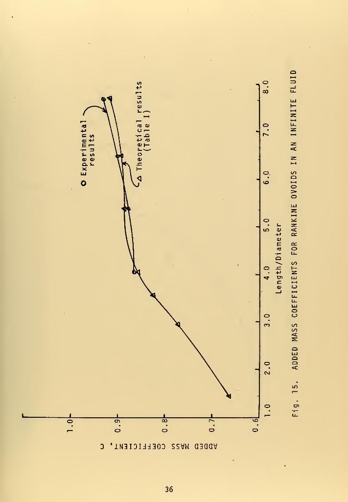
15. Added-mass coefficients for Rankine ovoids in aninfinite fluid 36
16. The wal
1
-proximi ty effect on the added mass of a
circular cylinder 37
17. The free-surface proximity effect on the added massof a circular cylinder 38


Symbol
a
C
U
D
L
K
TB#_
W
"a
T
f
5
n
Q
S.G.
NOMENCLATURE
Descripti on
distance to source or sink from origin ofcoordinate system
added mass coefficient
free stream velocity, uniform flow
diameter of Rankine ovoid at mid-length
length of Rankine ovoid
distance from centerline of Rankine ovoidto rigid bottom
distance from centerline of Rankine ovoidto free surface
test body number
weight of test body
added weight
displaced weight
total weight
period of oscillation
frequency of oscillation
L/D
b/D
h/D
potential function
stream function
radius of Rankine ovoid
source or sink strength
specific gravity


ACKNOWLEDGEMENTS
The author wishes to thank Professor T. Sarpkaya for
suggesting the research topic and for his guidance throughout
the investigation, from its inception to the completion of
the final manuscript.


I. INTRODUCTION
One of the most important problems in the design of
bodies moving through a fluid is the evaluation of the iner-
tial resistance of the fluid when the body is subjected to
accelerations or decelerations. This inertial resistance
affecting body motion is usually described in terms of an
apparent increase in the mass (added mass) of the body. The
fundamental concepts of the added mass and the historical
developments are amply described in most hydrodynamics books
(e .g. Robertson [1]) .
The added mass and the added-mass-moment of inertia are^ in
general, functions of the shape of the body, the direction
of body motion, the existing state of fluid motion (e.g.
motion from rest, motion from one steady state to another,
deceleration to rest from a steady state), the physical
properties of the fluid (i.e., density, viscosity, and
compressibility), and the proximity of other bodies, rigid
boundaries, or a free surface (fluid interface). Although in
theory the added-mass and added-mass-moment of inertia
coefficients can be computed for any body shape and flow
combination, the actual solution of the problem often proves
mathematically intractable. The greatest difficulties are
encountered in determining the added mass for bodies accelera-
ting from a state of steady motion and for bodies which are


not deeply submerged (bodies near a free surface) or bodies
which are too deeply submerged (near the ocean bottom).
Considerable analytical and experimental work has been
done on the determination of the added mass of bodies of
relatively simple shape immersed in a fluid medium of
infinite extent [1]. Good agreement has been obtained
between analytical and experimental results where the body
or the fluid is accelerated from rest. The understanding
and evaluation of the added mass for bodies accelerating
from a steady state (with separated fluid motion) to another
state are still at a formative stage and most of the current
design is based on empirical formulas (e.g., Morrison,
et al [2]) .
Concerning the effects of the free-surface or bottom
proximity on the added-mass coefficient, relatively few
analytical and experimental studies have been carried out
(e.g., Waugh and Ellis [3], Sarpkaya [4], Garrison [5],
Garrison and Berklite [6]). The analytical methods are
based on the image method, distributed sources, finite
element technique, etc. Experimental methods are based
mostly on the determination of the change of frequency of
the body oscillation in air and water. Analytical methods
are particularly convenient when the effect of damping is
ignored and the added-mass coefficient is rendered indepen-
dent of the frequency of oscillation of the body.


Rankine ovals and ovoids constitute a large family of
plane and axisymmetric bodies of special interest to hydro-
dynamicists and naval engineers. The added-mass coefficients
for these bodies may easily be calculated since only simple
singularities are involved in their definition in fluids of
Infinite extent. When these bodies are in the proximity of
a free surface and/or rigid boundary, however, the determina-
tion of the added mass is considerably complicated by the
need to introduce additional isolated or distributed
singularities. The problem is further complicated when the
free surface can be taken nei ther as a rigi d surface nor as a
surface of zero potential [1]. Under these circumstances,
it may be preferable to resort to simple experimental
techniques to determine the effect of the surface or bottom
proximity on the added mass of bodies of arbitrary shape.
The present work consists of the experimental determina-
tion of the added mass of Rankine ovoids of various length-
to-diameter ratios positioned at various distances from the
free surface or rigid bottom. The bodies were vibrated along
a line normal both to the free surface of the fluid and the
major axis of the body. The added-mass coefficients were
determined in terms of the appropriate governing parameters.
The results are in conformity with the previous findings for
other types of bodies in that the proximity of the free
surface decreases the added mass, whereas the proximity of
the rigid bottom increases it [3].


II. DEFINITION OF THE BODY SHAPE AND THE GOVERNING PARAMETERS
Rankine ovoids are the type of axisymmetric bodies
obtained by placing a three-dimensional (point) source and
sink, each of strength Q, at equal distances "a" from the
origin along a line parallel to a uniform flow. Potential
and stream functions are written in terms of the bipolar
coordinate system shown in Fig. 1 as:
^ = -Q/A-rrr-j + Q/47Tr2 + Ux
ij; = -Qcose^/^^ + Qcos02/^^ + U
(1)
CO
P(x,a))
*-X
Fig. 1. DEFINITION OF A RANKINE OVOID
The equation of the body contour is obtained by equating
the stream function to zero,
2t*J = 2^ (cose^ - cose2)
In terms of the parameter m = /Q/ZirUa^ one has,
o0)
(2)
—- = m^ (cose-j - cose2)
10


or. 0)= m
x+a x-a
/oT^+Tx+TP" /(D^ + (x-a)
(3)
Apparently, the absolute size of the body is controlled by
the source-sink distance "2a", whereas the length-to-diameter
ratio is determined by the parameter m. Since a stagnation
point exists at x=±L/2 taking the derivative of the potential
along the x-axis and equating it to zero, one has.
- 1]1
2m'(4)
The diameter at x=0 is obtained from Eq . (3) as,
4a24a
(5)
Since neither L/2 nor D/2 can be simply solved for, the
relationship between m and L/D must be evaluated numerically.
Results of such calculations are presented in Table I.
As discussed previously, the added-mass coefficient depends
upon the body shape, body motion, properties of the fluid
medium, and the proximity of either a free surface or rigid
boundary. In this work, the effects of the body shape and
the proximity of the free surface or rigid bottom were con-
sidered. For the Rankine ovoid, body shape is characterized
by the length-to-diameter ratio. The free-surface or the
bottom-proximity effect may be expressed in terms of the
ratios b/D and h/D (see Fig. 2). Thus, one has
added massC = -TTHncn1.rJHm.cc = f ( L / D , b / D , h / D
)
displaced mass ^ » / /(6)
n


provided that the viscous and compressibility effects are
ignored. Defining 6=L/D, n=b/D, and C=h/D, Eq. (6) may be
written as
C = f(6,n.C) (7)
If we consider the effects of the free-surface and bottom
proximity independently, by taking h/D=<» and b/D=°°
respectively, then we have
C = fi(6,n)» (free-surface proximity effect)
C = fpC^,?)* (bottom proximity effect)
J
(8a)
(8b)
7~7 7—7
—
7^—? 7—7—
7
/ / /—7
—
TT-
Fig. 2. DEFINITION OF THE BASIC PARAMETERS
It is the experimental determination of the functional rela-
tionships represented by Eqs. (8a) and (8b) that constitutes
the essence of this work.
As cited earlier, the viscous and compressibility effects
were ignored. The effect of compressibility may be neglected
when 27TfD/c<<l , where c is the speed of sound in the fluid
medium [7]. In fact, taking c=4700 ft/sec, and D=2 inches
(the largest value used in this work), one finds that f must
be considerably smaller than 4490 cps. As to the effect of
12


viscosity, an analysis of the forces acting on bodies oscil-
lating recti li nearly in a viscous fluid about a mean position
reveals that one part of the force results from the added
mass and is in phase with the oscillation. The second part
of the force, which opposes the body movement, is out of
phase with the acceleration and is thus a damping force pro-
ducing a decay in oscillation. The analytical results also
show that for small amplitudes of oscillation (up to about
D/10), the viscosity effects on added mass are quite
negligible [7].
13


Ul
E01
•— evj ro ^=1fe =<te =<»: =»fe
CD CQ CQ 03
I U) C £= I (/)
r— lO '^ '^ 'r— *0
Xn- E E Xr-(U O) 3 =S (DO)
«t.
at"Oc
>»u
tf)
1 (/)
•r- (O
X r—0) C7>
(O rO
C9T •*
CO
s.0)
+J +J • ^—
»
^ « F— •
C7>5 Q. V)•r- u> E<U«4- •1- CJ>
3 OT3.-^
+J a-—
^
.C 1 <u •
o>xi en CO•1- 3 s- E<U (O a> CT>
(/) 3^-^ E—
'
a:LUh- !-> .—>.
LU ^<-^ •
s: cn >, (/)
< •r- S- Eac 0) XI D>< 3--^«—
'
1—
•
o.
LU o-K
_J •—
1
*CO o<: > T
II1— o
UJ»LU
II^ O fT•
h-
1
:m£ &.z o«c (4-q:
00 CVJ CVJ 0000 VO VO 00I— 00 CO I—
f— CM
CO
in
Cft
CTl
vo
C\J I—
<y»
ro 00 o CM00 CO CT> 1^
f— f— CO
<T> CJ»
Lf> cn CO 00r— m LO in
CM CO
00
r-. «:!- >—CJ> "^d- r^ro in CO
lO^ o
o — —
roCO
oo00
COCO
CM
VO
CM
00
u:>
00
>»
a.s~ta
in CM in I— I— CM inI— <T> CO VO CM r^ VOa> 00 CO CO CO r^ VO
CM in ooin CO CM I—
r— o Ln CMlO o CO ^ 1— r>.
^^ o CM CO ^ ino • • • • •
CO ro 00in VO r^00 o '^
o — CM
O «* CT»
r— 00 en I— oCM CM I— I— VO
C7) o•r- s-LU a.
0) >>0) ^C/>
T3a>
• ctn •r-
XJ <oc •->
0)o
-aQ) 10
C7» 4->
C r—<o 3r— «/)
«4- (Us-
.C•-> r—•r- <a
S u•r-
m +JOi >»c n—o ta^- c
«(AQi osz 0)
uCM CM CM CM CM CM CO CO lO
CM
VO VO ^o *:»- ^— CM O^- r— CM ^ O o oo o O O O '- ^ o
o o O O O o o ,_
0)>
14


III. EXPERIMENTAL EQUIPMENT AND PROCEDURE
The experimental equipment consisted of a four-feet square
plexiglass tank with an adjustable false bottom, a pair of
parallel cantilever beams, a vibration triggering device, a
bridge amplifier meter, and a Monsanto programmable counter
timer.
Important considerations in the setting up of the
apparatus were the avoidance of the boundary-layer separation
and extraneous disturbances, adjustability of the position
of the test body relative to the free surface or solid
bottom, and the adoption of a suitable and repeatable
calibration procedure.
The test bodies (Fig. 4) were made of plexiglass or
aluminum and attached to the cantilever beams by two arms
(Fig. 5). An ideal solution to this aspect of the instru-
mentation would have been the use of "action at a distance"
whereby the body would be vibrated in the fluid without any
material involvement. Such a method was not explored
primarily because of the inordinate amount of instrumentation
required.
The detrimental effect of the use of two arms to attach
the test body to the cantilever beams was reduced by using
two thin-walled tubes rather than solid rods. Significant
reduction in weight and sufficient rigidity were realized in
this manner. An experimental comparison of the effect of the
arms (without the body) in air and water was performed. The
15


X
a:
D1
16


UJh—
t
QO
oo
en
17


o
1—L±J
Q
cn
18


results shown in Table II indicate that the axial frequency
of the vibration of the arms is little affected by immersion
in water.
TABLE II
FREQUENCY COMPARISON FOR EMPTY ARMS IN AIR AND IN WATER
* 2**Depth of arms Frequencysubmerged(i nches)
5
10
15
20
30
in ai;
(cps)'
1560
1580
1440
1508
1467
Frequency'in water(cps)2
1555
1590
1452
1524
1469
t**Rati
(col. 2/col. 3)
1 .0047
0.994
0.993
0.990
0.999
Length of arms below cantilever beams are equal for airand water
**Average of ten readings
Possible buoyant force effects due to the displacement of
water by the arms was considered, and found to have an effect
of 0.09% on frequency squared readings. This experiment was
performed using the fourth test body at a depth of ten inches
and by comparing the data with and without the added weight
equal to the displaced water.
Initially it was intended that the variation of the free-
surface or bottom proximity would be accomplished by changing
the length of the supporting tubes to the test body. However,
it was found that the preloading of the cantilever beams
resulted in the non-reproduci bi 1 i ty of the data. This pre-
loading is illustrated in Fig. 6 (beam deflections exaggerated)
19


f^ = 58-58 cps fjj = 57.95 cps
fjj = 580 09 cps
Fi . 6. PRELOADING EFFECTS
This difficulty was overcome by installing a stiffener bar
(Fig. 5) with the beams unloaded and subsequently varying
the free surface or bottom proximity by changing the water
level or adjusting the elevation of the false bottom.
A vibration triggering device was employed to insure
consistent initial deflections and to eliminate the human
element. It was designed to be adjustable in length so that
the variation of the natural deflection of the beams due to
the differing weights of the test bodies could be compensated
for. The triggering device was adjusted to provide an initial
deflection of 1/16 inch for all test bodies, thereby meeting
the criteria previously discussed concerning the effect of
viscosity, i.e., deflection <D/10.
20


The programmable counter-timer was used in the period-
averaging mode, with readings taken in milliseconds. It was
"zeroed" prior to each triggering, whereas the bridge
amplifier was "zeroed" prior to each set of ten runs for a
single data point.
The test bodies were weighed in air and in water on a
beam balance to determine their actual weight and the weight
of the water displaced. The results are shown in Table I.
Calibration curves were obtained for each test body,
utilizing clamped-on surcharges of known weight. Care was
exercised to distribute the weights symmetrically on the
test body. The data were plotted with period squared as
abscissa and known total weight as the ordinate in view of
their projected use.
A data run for a test body consisted of ten readings at
each variation of its position from the free surface or rigid
bottom, varying only one of these distances during a given
run. Calibration checks were performed before and after each
run
.
An initial "proof test" was performed using a cylinder
with end plates as the test body, and an added-mass coeffi-
cient of 0.988 was obtained, as compared to its theoretical
value of 1.0.
The major source of experimental error resulted from the
variation of period of vibration at a data point. For this
reason, the average of ten readings taken at each data point
was used to calculate the added mass. The root-mean-square
21


deviation from the average of the ten readings taken at any
given data point was found to be _< 0.02 milliseconds. This
deviation results in an error _<±0.5 gram in the determination
of total weight from the calibration curves. Since the added-
mass coefficient was calculated using added weight (W =W.-W),a u
this factor resulted in a deviation £ 0.0O6 in the added-mass
coefficient. Errors in test body weights and displaced
weights were negligible in comparison, being accurate within
±0.05 gram.
22


o inin «x>
CVi •
CM p^
II
ao _ioCM oCM CM z
^—^ t—
1
«/) >a •a:
c 3:oo Q
O.QJ I—
1
If) 10
CM r— O
T3 2:0) <i- q;
1— ITS
CM 3 UJcr zcC/1 t-
c ai
•r- U--M
ID (O Q.— LxJ
CM 1— 00•r- rj
t/) LU>Qc:
«f- ID
-0 2:CM
•r- 1—
1
t- 1—Q) <O- OH
QQt—
1
ir> _J(Tk ctf—
oo CT
(•siu6) (saBueijDjns uoLt^ejqLLeQ pue ploaq) ^qBiaM Le:^Oi
23


om
in u)1— -o
cou(U(A
•r-
O «—IT) t—
0)u
crCO
oo
4-»
(O
O «—LO I—CO •-I— o
«/)o
o -oo oCO •!-
r- S-
(U
oLT)
CVJ
ooCVJ
II
o_l
at—
I
o>
a:
a:o
O
CQ
00
en
oo o ooin
o oo oCO
(sui6) (sa6aeqDuns uoLt^euqLLeo pue ploaq :m6LaM) L^^oi
24


oo COo COCM •
N
QO ^«^
O C\J _la\ ^—^1— U) C3
"O Zc >—»
o >u <3:
0) 3:(/I
"f— oo r— 1—
1
o t— o00 •1— >*"" E o
LlJ
-o zQ) 1—
•
i~ i^(0 zo 3 <o CT a:
r^ t/7
4-> cc« o
o r— U-o r—vo •r— Qr— O LU
</) OOo ZD
*t- LUo >
O -o IDo o C_>
ID •1—
r— s- z:(U oa. 1—
t
1—
COO 1—
1
O -J'^^ <ct— o
ooCO
CT>
CD
Ooen
oo00
oo oovo
ooLO
(•sai6) (s36jieLj3uns uoL:;Bjqi[e3 pue ploaq) ^mBiaf/i ie:^oi
25


ooo>
o
o II
o00 Q^- CM —
^
^—>^ _iin-a C3c Zo 1—
1
u >o. <u •a:
o CO DCr*^ •1—
^ 1— o1— 1—
f
•1— oE >"^^ o-o IJJ
o (U zo S- 1—
1
VO fO :>^
^— 3 2:cr <cCO q;
LU
-Mto a:
Lf> t—*"
[^Li-
UJ10 >
M-
^«* -0^- 1—
1
•1— 1—S- <c(U orQ. CO
1—
•
-J<c
CO
ooCM
CTl
oo oo00
oo1^
oo oo oo
suj6) sa6wieL|Duns U0L:^eJqLLe^ pue PLOAQ) ^ij6l9m i^^oi
26


IV. DISCUSSION OF RESULTS
The added-mass coefficients for each test body, as deter-
mined experimentally, are shown in Figs. 11 through 14 as a
function of the free-surface or rigid-bottom proximity.
Figure 15 shows the relationship between the body shape
(L/D ratio) and the added-mass coefficient in a fluid of
infinite extent.
The added-mass coefficients shown in Fig. 15 were obtained
from Figs. 11 through 14, using the apparent constant value
attained beyond the distance at which the free surface or
rigid bottom appeared to exert very little or no influence.
The increase in C as L/D increases is as expected, since a
cylinder may be considered to be a Rankine ovoid with an
infinite L/D ratio, and since the added-mass coefficient for
a cylinder is larger than that for a finite axisymmetric
body (e.g., for a cylinder C = 1 whereas for a sphere
C = 0.5)
.
The free-surface and bottom-proximity effects are shown
in Figs. 11 through 14. The rate of change of the added-mass
coefficient as the proximity decreases is not the same for
all test bodies. The distance at which either the free
surface or rigid bottom ceased to affect the added-mass
coefficient is in proportion to the L/D ratio. This depen-
dency indicates that the influence of the free surface or
rigid bottom is exerted at a greater distance for bodies of
27


larger L/D ratios. The effect of the free-surface proximity
on the added-mass coefficient is more evenly distributed over
the influence distance than the effect of the rigid-bottom
proximity.
The added-mass coefficients determined for test bodies 1,
2, and 3 were independent of L/D for C£l » varying by less
than 4% in this region. This same consistency was obtained
for test bodies 2, 3, and 4 within the same proximity to the
free surface.
The effect of the free surface or bottom proximity on
the added mass of a Rankine ovoid may be calculated through
the use of distributed sources or the finite element method.
The former method requires the determination of the appro-
priate source-strength distribution over the body in such a
manner that the boundary conditions are satisfied both on the
body (zero normal velocity) and the bottom (zero normal
velocity) and/or at the free surface (^—^ + g^A = 0)[1].
As far as the free surface condition is concerned, for low
values of the Froude number F ( F=V//gD' where V is a
characteristic velocity), the second term in
m + g|i =
is negligible and the flow behaves as though the interface
were rigid so that (}) satisfies a second boundary-value problem
At the other extreme, the first term is negligible and the
surface condition corresponds to (^=0 . In terms of the image
method, the low Froude number case involves the normal kind
28


of images (positive), whereas the high Froude number case
involves inverse images. In the transitional regime the
situation is more complex and is frequency dependent.
In the present study, an exact analysis of the dependency
of the added mass of the Rankine ovoids on the bottom or
free-surface proximity has not been attemptted. Instead, an
approximate calculation based on the strip method has been
carried out. The strip method consists of the division of
an axisymmetric body into small axisymmetric cylinders,
evaluation of the added mass of each disk-Hike segment through
the use of the added-mass coefficients obtained for a circular
cylinder of corresponding position relative to the bottom or
free surface, and summing the coefficients for all the
elements. Obviously, this procedure ignores the effect of
the three-dimensionality of the body. Furthermore, the
added-mass coefficients so obtained approach unity for the
infinite fluid case rather than those appropriate for a
Rankine ovoid. Be that as it may, the strUp method provides
a quick estimation of the variation of the added-mass coeffi-
cient with distance to the wall or the free surface.
In the present calculation, the results of the analysis
carried out for a circular cylinder by Mliller [8] and Yamamoto,
et al [9] through the use of doublets and the image method
were used. Figures 16 and 17 show the variation of the
added-mass coefficient for a circular cylinder as a function
of distance from the wall and the free surface (only the high
29


Froude number or ()) = case) respectively. Evidently, Fig. 16
also represents the effect of the free-surface proximity for
the low Froude number or -^y = case.
The added-mass coefficients calculated through the use
of Figs. 16 and 17 and the strip method are shown on Figs. 11
through 14. It is apparent from a comparison of the cal-
culated results with those obtained experimentally that the
strip method yields fairly accurate results, particularly
for bodies close to a rigid plane wall. As expected, the
calculations become increasingly more accurate as L/D
increases and the proximity to the wall decreases. As noted
previously, the limiting values corresponding to the infinite
fluid case differ significantly because of the role played by
the three-dimensionality of the body. In other words, in
the close vicinity of a wall, the wal 1 -proximi ty effect
outweighs the three-dimensionality effect.
The added-mass coefficients calculated through the use
of the strip method for the free surface case (both for (|) =
and -g^=0 conditions) are not as satisfactory as those calcu-
lated for the rigid wall case. Be that as it may, a careful
examination of the experimental data and the calculated
results shows that one could predict with a sufficient degree
of accuracy the effect of both the wall and free-surface
proximity if one were to shift the calculated curves downward
so that their asymptotic values coincided with those obtained
experimentally. This procedure is rather appealing considering
30


the fact that the added-mass coefficients for Rankine bodies
immersed in an infinite fluid may be calculated (see Table I)
thus providing the the asymptotic values to be used for the
procedure suggested above. Finally, it should be noted that
the added-mass coefficients discussed above are not the same
for the Rankine ovoids moving against the wall (or the free
surface) or parallel to it. This is true only for a circular
cylinder.
31


o
0>
a.•^s.+j(/)
E >>o J3+*+J ,^~» -oo 00 (U
ja II+J
tr (O
T3 1^•r— +j 3o> (O o•^ ^-&- 0) ro
o OC7> <o 1
r\
I
(U
« 8> II --^
I— II
to kjS Q}
U I—•r- S_^4-> O (O
O O (U
O) <u
x: «- «/)
+j o—
-
G<1Q)ufO^-s.3M<UQ}.^~»
i- IT)
*- II
«jj<
CT>
C 4->
t— nj
IDO lO
« t- •
LD 0) r««
<u II
E<o o't— "^.^
o _i
o zc•r- h^o 1—
«
> 3oO Q• <u 1-^
^ c O•^ 5»^ ocfO UJon z"^ 1—
1
0) i^o z:c <rO q:4->
to LlJ
o •1^ 3:• Q 1—
CO>> Qi•!-> O•r— u.E•r- »—X z:o UJs- 1—
1
O- o1—
1
U-• • U-
o o LU• •r— o
CVJ oOl 00
CO
oo
ID
OO)
LT) n C\J r- O CT>
o00
o oCO
o o
3 *:^U9L0L^^903 SSBW pappv
32


Q}
O5 >,
o (O4-» o»J..^-^
O LO^ II
tr-o•r- +*cn lO
•r—
s- Q)
OO) «o
c:«4-•r- s-
.C 3o (/)
<0
o (Us- <u
a. s-
a-«4-«o •^.^
-e-4^
a(OM-S-
3«/)
O)
s- inM- II
o>c +->
•1- (O
o E(O oo +J$- -MQ. OQ-JDro
O
(U
II
o
o
o
«o 3:•r- I—Q H-l
3-o•I- QO •-> OO >O
c<aa:
(Uoc«34->
(/)
•r—O>>!->
o&-
o a.
CVJ
a:
in
o
I—
I
oc_>
to
ooQ
<st
CT>
3 *:iuaLD 1^:^903 ssbw pappv
33


o
i-
0)4->
O)
ElO
•r—Oo
o •"-
• o^ >o
COCO
in
II
Q
QI—
I
o:>o
rO <a:
OC or
<U LUO DC
o c h-• rO
CO 4-> o:U) o•r- u.O
h->» z!-> LU•r- t—
1
E (_>
•r— 1—
1
X U.o U-s- LlJ
o D. o• o
CM• • ooo oo•r- <:+* 2:»oq: o
UJoo
CO
o>
in CO cvj
o00
o o Oin
o
3 t^uaioL^^aoQ ssbw pappv
34


. "Oo
/—<^—
N
JCD> C7>
+J
c c 0)
E•r- •!-
(/) (O
lO to a.
0) <u•^"
&. s- i-
o o *->
c <u (/)
i-"0>>
UJ»W» -Oir .11
-
-o o -o^—y—
^
+J
E «o
O ^~
+* 34->-— oo in f""
Xi II(O
^ o^
1
•r- +*cn «o•r— \
$- 0)\O)
cn <o
C «4-
•1- $-
^ 3O to(O
O 0)
s- <u
o. $-
D.«^«o
»4
»4
oIQ
13
<u
S- lf>
«4- II
C 4->
•r- «0
o Eto oo +->
S- +Ja. o
o o• •
in
II
s- o<u "•
—
4-> _j0)
E JC(O H-•1— 1—
•
o 3o -o O
• •r— t—
1
**. o o> >o o(U LUc z•r- 1—
1
-^ iZc srlO <ca: q:
0) UJo u n:
• c »—CO ro
»-> an«/) o•r- U-O
1—>> z4-> UJ•1— 1—
1
E o•r- 1—
1
X U-o U-
o s- UJ• O- o
CVJ o.. ooo oo•r- <:4-> s:to
a: QUJOQ
in
ocn
3 •^uaiDi^^soQ SSCW-P9PPV
35

M O00
o
o. (/)• o
vo 1—
1
o>o
inJ- z:0) <4-> q:(U
E DC<o o
oCO
^ I—4-> z:
C I—
I
o
oo
oCVJ
oo
LD
en
o00
o ovo
o
3 *iN3IDIJJ303 SSVW QHOaV
36


.3.«/)
oO L
jQ1=
Q.
-O T3
NsNV^^^'^^^
DC
o
toto<
aa<:
o
CJ
CO
oeo >-^^ I—JH I—
I
C\J
Xo
VO
oo
o^
oCM
00 t^ CM
37

0)o10
u3M **
a01 vt0> o{. u
COCO
ao
oI—
o
CO H-
1
• Xo o
ot:
D_q:
UJ LUO Qca: 2:U- 1—
1
CVJ Qi _l• rs >-o t/> o
UJ q;UJ cCa: _iU- IDoUJ q:
I— o
oo
C7)
38

V. CONCLUSIONS
The effects of the free-surface and plane-wall proximity
on the added-mass coefficient of Rankine ovoids oscillating
vertically have been determined experimentally.
The results have shown that the bottom proximity increases
the added mass and the free-surface proximity decreases it.
Furthermore, the added mass increases with increasing length-
to-diameter ratio and approaches that predicted analytically
for an infinitely long cylinder. An approximate analysis
based on the strip method and the cylinder results has shown
that the bottom-proximity effect on the added mass of Rankine
ovoids may be predicted with sufficient accuracy. Finally,
it is noted that both the bottom and free-surface effects may
be predicted to a first order of approximation by matching
the asymptotic values of the added-mass coefficients for the
cylinder and the Rankine ovoids.
39

LIST OF REFERENCES
1. Robertson, J. M., Hydrodynamics in Theory and Application ,
Prentice-Hall, Inc., Englewood Cliffs, N. J., 1965.
2. Morrison, J. R., ejt aj_, "The Force Exerted by SurfaceWaves on Piles," Transactions, AIME , Vol. 189, 1950.
3. Waugh, J. G., and Ellis, A. T., "Fluid Free SurfaceProximity Effect on a Sphere Vertically Accelerated fromRest," J. Hydronauti cs , Vol. 3, No. 4, Oct. 1969.
4. Sarpkaya, T., "Added Mass of Lenses and Parallel Plates,"J. Engineering Mechanics Division Proceedings, ASCE ,
Vol . 86, No. EMS, June 1960.
5. Garrison, C. J., "Added Mass of a Circular Cylinder inContact with a Rigid Boundary," J . Hydronauti cs , Vol. 6,No. 1 , Jan. 1972.
6. Garrison, C. J., and Berklite, R. B., "Impulsive Hydro-dynamics of Submerged Rigid Bodies," J. EngineeringMechanics Division, Proceedings, ASCE , Vol. 99, No. EMI,Feb. 1973.
7. Rosenhead, L., ed.. Laminar Boundary Layers , OxfordUniversity Press, Oxford, 1963.
8. Muller, von Wilhelm, "Systeme von Doppelquel 1 en in derebenen Strbmung, insbesondere die Strbmung urn zweiKreiszyli nder, " Ztschr, fiir Angew. Math, und Mech., Bund 9,Helf 3, pp 200-213, Juni 1929.
9. Yamamoto, T., Nath, J., and Slotta, L., "Yet AnotherReport on Cylinder Drag or Wave Force on HorizontalSubmerged Cylinders," Oregon State University BulletinNo. 47, April 1973, Corvalis, Oregon.
40


INITIAL DISTRIBUTION LIST
1. Defense Documentation CenterCameron StationAlexandria, Virginia 22314
2. Library, Code 0212Naval Postgraduate SchoolMonterey, California 93940
3. Chairman, Code 59Department of Mechanical EngineeringNaval Postgraduate SchoolMonterey, California 93940
4. Professor T. Sarpkaya, Code 59ScDepartment of Mechanical EngineeringNaval Postgraduate SchoolMonterey, California 93940
5. Professor C. J. Garrison, Code 59GmDepartment of Mechanical EngineeringNaval Postgraduate SchoolMonterey, California 93940
6. LT Monty G. Fickel , USN978 Madison St.Monterey, California 93940
No. Copies
2
41


UNCLASSIFIEDSECURITY CLASSIFICATION OF THIS PAGE (Whmn Oa(a En»»r«d)
REPORT DOCUMENTATION PAGE READ INSTRUCTIONSBEFORE COMPLETING FORM
REPORT NUMBER 2. GOVT ACCESSION NO. 3. RECIPIENT'S CATALOG NUMBER
4. riTLZ (and Subtitle)
Bottom and Surface Proximity Effectson the Added Mass of Rankine Ovoids
5. TYPE OF REPORT ft PERIOD COVERED
Master ' s Thesi s
;
December 1973« PERFORMING ORG. REPORT NUMBER
7. AUTHORr*;
Monty George Fickel
•. CONTRACT OR GRANT NUMBERC*;
9. PERFORMING ORGANIZATION NAME AND ADDRESS
Naval Postgraduate SchoolMonterey, California 93940
10. PROGRAM ELEMENT, PROJECT. TASKAREA a WORK UNIT NUMBERS
II. CONTROLLING OFFICE NAME AND ADDRESS
Naval Postgraduate SchoolMonterey, California 93940
t2. REPORT DATE
December 197313. NUMBER OF PAGES
4314. MONITORING AGENCY NAME & ADDRESSr// rfi//«fenf from Controlling Oltlcu)
Naval Postgraduate SchoolMonterey, California 93940
15. SECURITY CLASS, (at thit report)
UNCLASSIFIEDISa. DECLASSIFICATION/ DOWN GRADING
SCHEDULE
16. DISTRIBUTION STATEMENT (ol thie Report)
Approved for Public Release; Distribution Unlimited.
17. DISTRIBUTION STATEMENT (ol the abetrmct entered In Block 20, II dillerent horn Report)
18. SUPPLEMENTARY NOTES
19. KEY WORDS (Continue on reveree elde II neceeemry and Identity by block number)
added massvirtual massRankine ovoids
20. ABSTRACT (Continue on reveree elde 11 neceeemry and Identity by block number)
The free-surface and bottom-proximity effects on the addedmass of Rankine ovoids of various length-to-diameter ratioswere experimentally investigated by vectically oscillating theovoids normal to their major axis.
The results have shown that the bottom-proximity increasesthe added mass and the free-surface proximity decreases it.
DD,:°r73 1473(Page 1)
EDITION OF 1 NOV 65 IS OBSOLETES/N 0102-014-6601
I
UNCLASSIFIED
42SECURITY CLASSIFICATION OF THIS PAGE (When Dale Entered)


UNCLASSIFIEDCtCUKITY CLASSIFICATION OF THIS PAGEfHTi.n Data Enfnd)
Furthermore, the added mass increases with increasing length-to-diameter ratio, i.e., for more cylinder-like ovoids, andapproaches that predicted analytically for an infinitely longcylinder. Finally, an appropriate analysis based on thestrip-method and the cylinder results has shown that thebottom-proximity effect on the added mass of Rankine ovoidsmay be predicted with sufficient accuracy. The prediction ofthe surface-proximity effect requires more refined methods.
DD Form 1473 (BACK) iiMriAccicTcn1 Jan 73 UNCLASSI FI ED
S/N 0102-014-6601 security classification of this PACEflWian Dmtm Enffd)
43


ThesisF385
c.l
ThesisF385c.l
1 b 7(^^^
FickelBottom an*! surface
proximity effects on
the added mass of Ran-
kine ovoids.
.

thesF385
Bottom and surface proximity effects on
3 2768 002 00137 2DUDLEY KNOX LIBRARY