bootsmotoren von volkswagen marine… · · 2018-02-08part number manufacturer part number...
TRANSCRIPT

Individual-InstrumentierungIndividual Instrumentation
Einbauanleitung EA02Installation Instruction EA02
Bo
otsm
oto
ren
von
Vo
lksw
ag
en M
ari
ne
TDI 100-5TDI 120-5TDI 150-5TDI 150-5D
SDI 55-5SDI 75-5
SDI 40-4SDI 50-4SDI 60-4
Einbauanleitung EA02Installation Instruction EA02
© 2005 Volkswagen Marine
Die Texte, Abbildungen und Normen in dieser Anleitung basieren auf dem Informations-stand zum Zeitpunkt der Drucklegung. Nachdruck, Vervielfältigung oder Übersetzung,auch auszugsweise, ist ohne schriftliche Genehmigung von Volkswagen Marine nichtgestattet. Alle Rechte nach dem Gesetz über das Urheberrecht bleiben VolkswagenMarine ausdrücklich vorbehalten. Änderungen vorbehalten.Redaktionsschluss 05/05
The texts, illustrations and standards in this manual are based on the information available at the time of print. Reprinting, reproduction or translation, in whole or in part,is not permitted without the written approval of Volkswagen Marine. All rights accordingto the applicable copyright laws are expressly reserved by Volkswagen Marine. Subject to change. Print status 05/05
Postfach/POB 31 11 76, 38231 Salzgitter, GermanyAusgabe/Edition 05/05 Drucknummer/Publication Number 065.A91.A02.00/20
❀ Dieses Papier wurde aus chlorfrei gebleichtem Zellstoff hergestellt.This paper was bleached without the use of chlorine.
EA02_0505_00_20.qxd 03.05.2005 10:47 Uhr Seite 1

1
Individual Instrumentation
Volkswagen Marine offers you the possibility to indivi-dually design your cockpit.You can select from the components described inthese installation instructions.
Safety precautions:
♦ When installing this instrumentation, care must betaken that the electrical lines are carefully and pro-perly laid.
♦ Cable plugs must be plugged in securely and enga-ged to ensure correct functioning.
♦ Additional voltage drops for other instruments ordevices may only be connected to the terminal strip(X14) of the operating unit (max. 2 ampere each forKl.15 -ignition on- and Kl.30 -permanent live-).
♦ The contact on the terminal strip X14-3 -dimmerlighting- should be used for lighting these instru-ments or devices.
General Information:
A comprehensive description of the individual func-tions for the revolution counter’s multifunction displaycan be found in the operation manual and supplemen-tal operation manual in your on-board booklet.
2
Overview of the scope ofsupply
1 - Rev. counter♦ with multi-function display♦ Description ⇒ page 22♦ Display range
0...4000 RPM
2 - Operating unit♦ with connection for diagnostic
system tester
3 - Indicator lamp♦ Qty 3♦ for voltmeter, water tempera-
ture indicator and oil pressureindicator
♦ to be built in to the back of therespective instrument beforeassembly
EA2--0021
1
8
7
2
56 4
3

3
4 - Wiring harness complete♦ Description ⇒ page 9
5 - Ignition switch♦ with 2 ignition keys♦ Description ⇒ page 21
6 - Water temperature indicator♦ Description ⇒ page 19♦ Display range
40°...120°
7 - Oil pressure indicator♦ Description ⇒ page 20♦ Display range
0...5 bar
8 - Voltmeter♦ Description ⇒ page 18♦ Display range
8...16 Volt
EA2--0021
1
8
7
2
56 4
3
4
Listing of instrument set 065 800 547 B:
Quan-tity
Part NumberManufacturer
Part NumberVolkswagen
Marine
Designation
1 - 065 959 714 Operating unit
1 N 02 012 911 065 920 800 Rev. counter
1 N 02 124 106 065 857 002 Oil pressure indicator
1 N 02 321 602 065 857 003 Water temperatureindicator
1 N 02 410 802 065 857 001 Voltmeter
1 32 83 50 065 905 845 Ignition switch
1 - 065 951 307 Buzzer
1 - 065 971 086 Line for voltmeter
1 - 065 971 086 A Line for oil pressureindicator
1 - 065 971 086 B Line for watertemperature indicator
1 - 065 971 086 C Line for rev. counter
1 - 065 971 086 D Line for ignition switch
3 N 05 800 762 2Y1 919 240 Indicator lamp

5
Operating unit (front side)
1 - Operating unit♦ Installation template⇒ page 25
2 - Control lamp for glow plugsystem and engine fault
3 - Button for dimmer regulationof the instrument lighting
4 - Acknowledge button foracoustic signal
5 - Button for multifunction dis-play♦ You will find information on
this in the operation manualand supplemental operationmanual in your on-board boo-klet.
6 - Cover for diagnostic connec-tion♦ Connection ⇒ page 24
EA2--0012
1 3
6
2 4 5
6
Operating unit (rear side)
1 - Operating unit♦ Installation template⇒ page 25
2 - Connection plug T22♦ white♦ from the operating unit to the
central electrical system♦ Contact assignment⇒ page 10
3 - Connection plug T22a♦ from the operating unit to the
flying bridge♦ Contact assignment⇒ page 12
4 - Connection plug T3♦ from the operating unit to the
ignition switch♦ Contact assignment⇒ page 14
5 - Fuse (2 ampere)♦ F2 terminal 30 (Permanent
live)
EA2--0005
14
1
7
2 3 4 5 6
8
13
12 11 10 9

7
Continued
6 - Fuse (2 ampere)♦ F1 terminal 15 (ignition on)
7 - Relay for instrument lighting
8 - Connection plug T5♦ from the operating unit to the
oil pressure indicator♦ Contact assignment⇒ page 16
9 - Connection plug T6♦ from the operating unit to the
water temperature indicator♦ Contact assignment⇒ page 16
10 - Buzzer
11 - Connection plug T12♦ from the operating unit to the
rev. counter♦ Contact assignment⇒ page 15
EA2--0005
14
1
7
2 3 4 5 6
8
13
12 11 10 9
8
12 - Connection plug T4♦ from the operating unit to the
voltmeter♦ Contact assignment⇒ page 14
13 - Connection strip X14♦ Operating unit terminal strip♦ Contact assignment⇒ page 17
14 - Gasket♦ Renew if damaged
EA2--0005
14
1
7
2 3 4 5 6
8
13
12 11 10 9
9
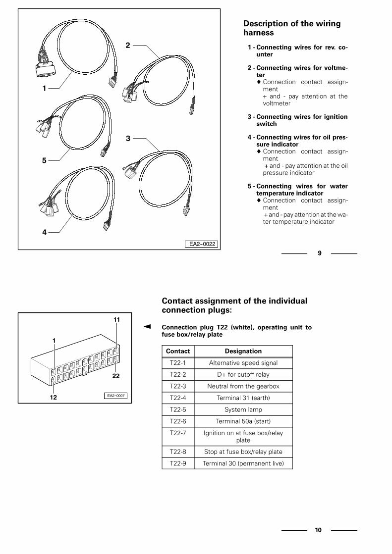
Description of the wiringharness
1 - Connecting wires for rev. co-unter
2 - Connecting wires for voltme-ter♦ Connection contact assign-
ment+ and - pay attention at thevoltmeter
3 - Connecting wires for ignitionswitch
4 - Connecting wires for oil pres-sure indicator♦ Connection contact assign-
ment+ and - pay attention at the oilpressure indicator
5 - Connecting wires for watertemperature indicator♦ Connection contact assign-
ment+ and - pay attention at the wa-ter temperature indicator
EA2--0022
1
5
4
2
3
EA2--0007
1
22
12
11
10
Contact assignment of the individualconnection plugs:
Connection plug T22 (white), operating unit tofuse box/relay plate
Contact Designation
T22-1 Alternative speed signal
T22-2 D+ for cutoff relay
T22-3 Neutral from the gearbox
T22-4 Terminal 31 (earth)
T22-5 System lamp
T22-6 Terminal 50a (start)
T22-7 Ignition on at fuse box/relayplate
T22-8 Stop at fuse box/relay plate
T22-9 Terminal 30 (permanent live)

EA2--0007
1
22
12
11
11
Continued
Contact Designation
T22-10 Water temperature switch
T22-11 Water temperature sender
T22-12 Neutral at fuse box/relay plate
T22-13 Oil pressure switch
T22-14 Sensor for water in fuel
T22-15 Alarm relay acknowledgement
T22-16 Sensor for water level
T22-17 CAN-Low
T22-18 Buzzer
T22-19 Charge monitoring
T22-20 K line
T22-21 Oil pressure sender
T22-22 CAN-High
EA2--0019
12
22
11
1
12
Connection plug T22a (black)Operating unit to the flying bridge
Contact Designation
T22a-1 External speed signal
T22a-2 Instrument lighting earth
T22a-3 Neutral from the main panel
T22a-4 Terminal 31 (earth)
T22a-5 System lamp
T22a-6 Terminal 50a (start)
T22a-7 Terminal 15 (ignition on) fromthe main panel
T22a-8 Stop at fuse box/relay plate(over the main panel)
T22a-9 Terminal 30 (permanent live)
T22a-10 Water temperature switch
T22a-11 NMEA-A (navigation system)
T22a-12 Neutral
T22a-13 Oil pressure switch
T22a-14 Sensor for water in fuel

EA2--0019
12
22
11
1
13
Continued
Contact Designation
T22a-15 Alarm relay acknowledgement
T22a-16 Sensor for water level
T22a-17 CAN-Low
T22a-18 Buzzer
T22a-19 Charge monitoring
T22a-20 Dimmer button
T22a-21 NMEA-B (navigation system)
T22a-22 CAN-High
EA2--0018
13
EA2--0017
1 2
3 4
14
Connection plug T3 (white)Operating unit to the ignition switch
Contact Designation
T3-1 Terminal 30 (permanent live)
T3-2 Terminal 15 (ignition on)
T3-3 Terminal 50a
Connection plug T4 (black)Operating unit to the voltmeter
Contact Designation
T4-1 Terminal 15 (ignition on)
T4-2 Terminal 31 (earth)
T4-3 Instrument lighting
T4-4 D+
EA2--0016
1
7
12
6
15
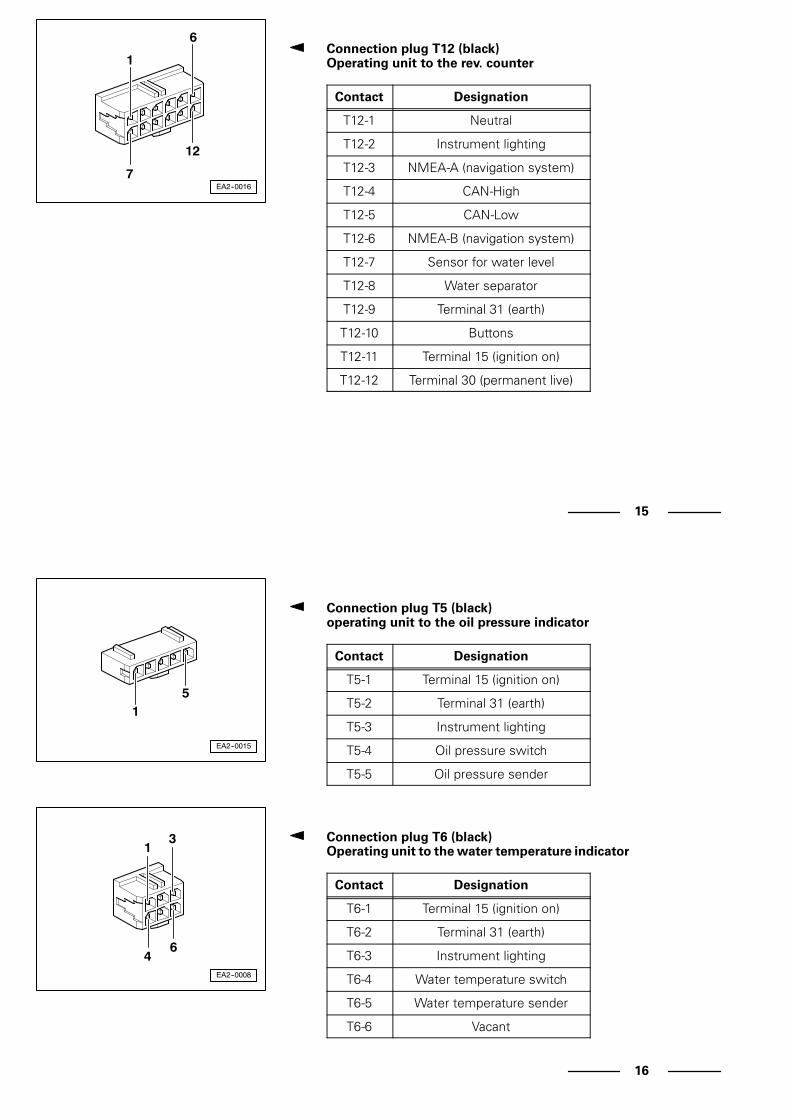
Connection plug T12 (black)Operating unit to the rev. counter
Contact Designation
T12-1 Neutral
T12-2 Instrument lighting
T12-3 NMEA-A (navigation system)
T12-4 CAN-High
T12-5 CAN-Low
T12-6 NMEA-B (navigation system)
T12-7 Sensor for water level
T12-8 Water separator
T12-9 Terminal 31 (earth)
T12-10 Buttons
T12-11 Terminal 15 (ignition on)
T12-12 Terminal 30 (permanent live)
EA2--0015
15
EA2--0008
13
46
16
Connection plug T5 (black)operating unit to the oil pressure indicator
Contact Designation
T5-1 Terminal 15 (ignition on)
T5-2 Terminal 31 (earth)
T5-3 Instrument lighting
T5-4 Oil pressure switch
T5-5 Oil pressure sender
Connection plug T6 (black)Operating unit to the water temperature indicator
Contact Designation
T6-1 Terminal 15 (ignition on)
T6-2 Terminal 31 (earth)
T6-3 Instrument lighting
T6-4 Water temperature switch
T6-5 Water temperature sender
T6-6 Vacant

EA2--0006
17
8
14
17
Terminal strip X14 (grey)Operating unit
Contact Designation
X14-1 NMEA-A (navigation system)
X14-2 NMEA-B (navigation system)
X14-3 Instrument lighting
X14-4 External speed signal
X14-5 Terminal 31 (earth)
X14-6 Terminal 31 (earth)
X14-7 D+ cutoff relay
X14-8 Terminal 15 (ignition on)
X14-9 Terminal 30 (permanent live)
X14-10 Neutral from the gearbox
X14-11 Neutral at fuse box/relay plate
X14-12 Neutral at flying bridge
X14-13 K line
X14-14 Vacant
EA2--0002
A 1
2
3
4
18
Description of the instruments andcomponents:
Voltmeter
Located on the rear side -A- of the voltmeter are theelectrical connections, with the following contact as-signment:
Contact Designation
1 Instrument lighting
2 Warning lamp
3 Terminal 15
4 Terminal 31 (earth)
Note:
When connecting, pay attention to the correct desi-gnation of the contact assignment (+ and -).

EA2--0014
A 1
2
43
5
19
Water temperature indicator
Located on the rear side -A- of the water temperatureindicator are the electrical connections, with the follo-wing contact assignment:
Contact Designation
1 Instrument lighting
2 Warning lamp
3 Water temperature sender
4 Terminal 15
5 Terminal 31 (earth)
Note:
When connecting, pay attention to the correct desi-gnation of the contact assignment (+ and -).
EA2--0003
A 1
2
3
45
20
Oil pressure indicator
Located on the rear side -A- of the oil pressure indica-tor are the electrical connections, with the followingcontact assignment:
Contact Designation
1 Instrument lighting
2 Warning lamp
3 Oil pressure sender
4 Terminal 15
5 Terminal 31 (earth)
Note:
When connecting, pay attention to the correct desi-gnation of the contact assignment (+ and -).
EA2--0004
A
2
3
1
21
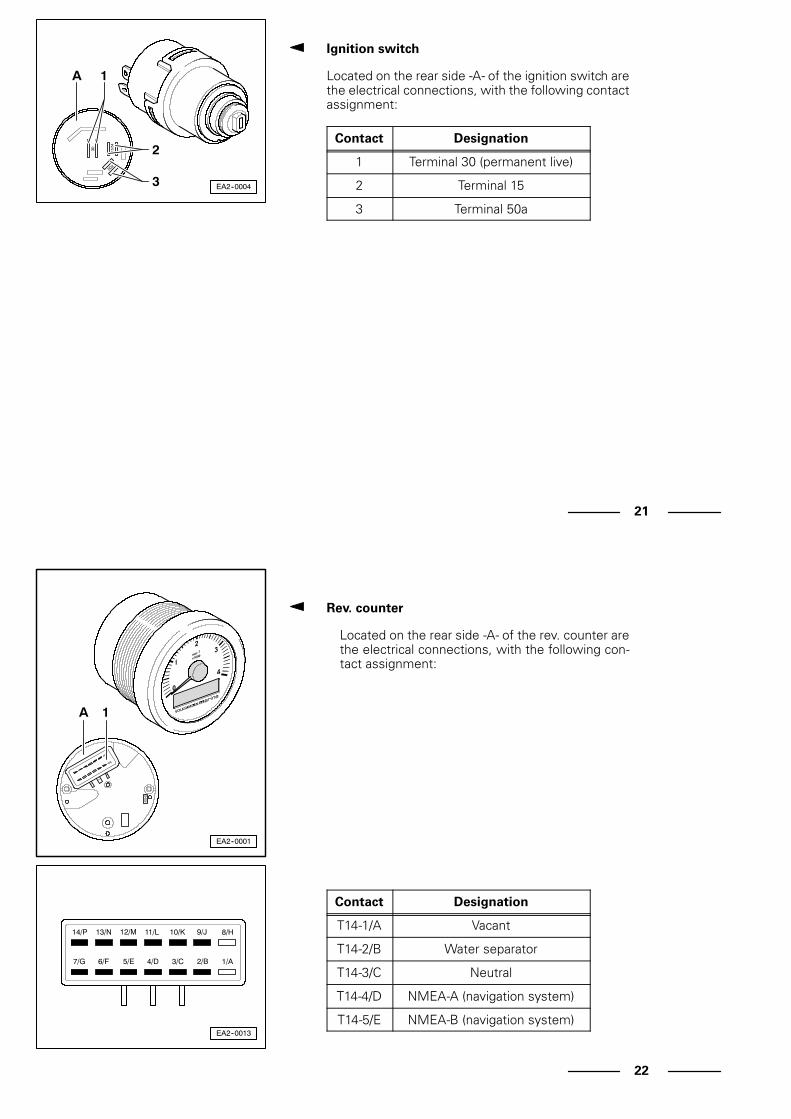
Ignition switch
Located on the rear side -A- of the ignition switch arethe electrical connections, with the following contactassignment:
Contact Designation
1 Terminal 30 (permanent live)
2 Terminal 15
3 Terminal 50a
EA2--0001
1A
EA2--0013
7/G 6/F 5/E 4/D 3/C 2/B 1/A
14/P 13/N 12/M 11/L 10/K 9/J 8/H
22
Rev. counter
Located on the rear side -A- of the rev. counter arethe electrical connections, with the following con-tact assignment:
Contact Designation
T14-1/A Vacant
T14-2/B Water separator
T14-3/C Neutral
T14-4/D NMEA-A (navigation system)
T14-5/E NMEA-B (navigation system)

EA2--0013
7/G 6/F 5/E 4/D 3/C 2/B 1/A
14/P 13/N 12/M 11/L 10/K 9/J 8/H
23
Continued
Contact Designation
T14-6/F Terminal 31 (earth)
T14-7/G Terminal 30 (permanent live)
T14-8/H Vacant
T14-9/J CAN-High
T14-10/K CAN-Low
T14-11/L Probe
T14-12/M Sensor for water level
T14-13/N Instrument lighting
T14-14/P Terminal 15 (ignition on)
EA2--002021
24
Connection for system tester (self-diagnosis)
- Unscrew the 2 fastening screws of the cover on theoperating unit -1-.
- Connect the diagnosis plug -2- from the system te-ster to the operating unit connection.
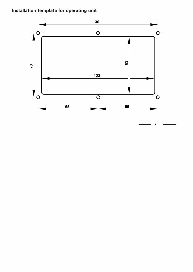
130
123
70
65
63
65
Installation template for operating unit
25

Individual-InstrumentierungIndividual Instrumentation
Einbauanleitung EA02Installation Instruction EA02
Bo
otsm
oto
ren
von
Vo
lksw
ag
en M
ari
ne
TDI 100-5TDI 120-5TDI 150-5TDI 150-5D
SDI 55-5SDI 75-5
SDI 40-4SDI 50-4SDI 60-4
Einbauanleitung EA02Installation Instruction EA02
© 2005 Volkswagen Marine
Die Texte, Abbildungen und Normen in dieser Anleitung basieren auf dem Informations-stand zum Zeitpunkt der Drucklegung. Nachdruck, Vervielfältigung oder Übersetzung,auch auszugsweise, ist ohne schriftliche Genehmigung von Volkswagen Marine nichtgestattet. Alle Rechte nach dem Gesetz über das Urheberrecht bleiben VolkswagenMarine ausdrücklich vorbehalten. Änderungen vorbehalten.Redaktionsschluss 05/05
The texts, illustrations and standards in this manual are based on the information available at the time of print. Reprinting, reproduction or translation, in whole or in part,is not permitted without the written approval of Volkswagen Marine. All rights accordingto the applicable copyright laws are expressly reserved by Volkswagen Marine. Subject to change. Print status 05/05
Postfach/POB 31 11 76, 38231 Salzgitter, GermanyAusgabe/Edition 05/05 Drucknummer/Publication Number 065.A91.A02.00/20
❀ Dieses Papier wurde aus chlorfrei gebleichtem Zellstoff hergestellt.This paper was bleached without the use of chlorine.
EA02_0505_00_20.qxd 03.05.2005 10:47 Uhr Seite 1