boondocker nitrous system installation instructions for ... for skidoo rev.pdf · boondocker...
TRANSCRIPT

BoonDocker Liquid Nitrous – 1589 Hollipark Dr. Idaho Falls, ID 83401 – (208) 542-4411
website: www.boondockers.com - email: [email protected] Revised 01-13-04 Page 1 of 12
BoonDocker Nitrous System Installation Instructions for Skidoo REV Snowmobile
Before you begin, please read all the instructions below and check kit contents. Note: The air box will need to be modified and the sparkplug holder will need to be trimmed off when installing this kit.
Nitrous Kit Contents: Quality check by: ___1 – Nitrous Manifold with fittings installed ___1 – 5-hole nozzle ___1 – plastic vacuum check valve ___1 – 12” x 3/16” vent tubing ___1 – Plastic Barbed Tee – 1/4” ___1 – Plastic barbed Tee – 3/16” ___1 – Nitrous Bottle with valve ___1 – 4AN x 1/8” NPT fitting for bottle ___1 – 1/8” NPT plug for bottle ___1 – REV bottle bracket ___2 – bottle clamps ___1 – high pressure braided hose (52”)
___1 – 12” length of 1/8” black nylon hose ___1 – solenoid ___1 – solenoid holding bracket and self-tapping screw ___1 – 1/8” NPT x 1/8” OD compression fitting for solenoid ___1 – 1/8” NPT fitting with Nitrous Filter for solenoid ___1 – 4AN adapter for Nitrous Filter on solenoid ___1 – pushbutton switch ___1 – mounting clamp for pushbutton switch ___1 – Rectifier ___4 – female electrical connectors ___4 – electrical butt connectors
Tools Required: Drill + bits (3/4”, 1/4”, 1/8”) Wire stripper / crimper tool Side cutters 5/32”and 7/32” allen wrenches Basic wrench set Flat blade screwdriver Hacksaw Teflon Tape
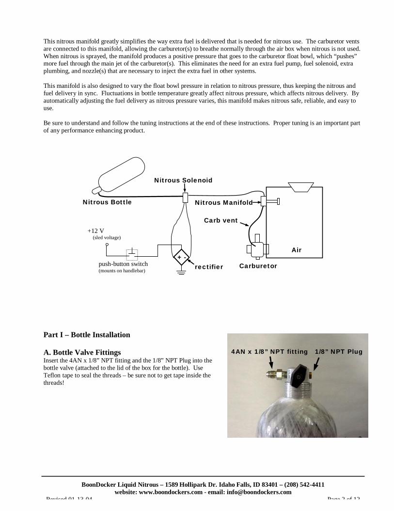
Theory of Operation: A common misconception about nitrous oxide is that it is explosive or flammable. Nitrous by itself does not burn, nor is it explosive. At 565 deg. F, nitrous oxide (N20) breaks apart and forms two parts nitrogen and one part oxygen. Inside an engine, this added oxygen speeds up the combustion process (the nitrogen plays an important part in buffering the reaction). Whenever nitrous is used, additional fuel is necessary, otherwise the added oxygen will act as a blow-torch inside your engine. When used properly, nitrous oxide provides the same benefits as turbo charging or supercharging your engine (extra power is made by burning more fuel and oxygen), but without the added cost or complexities. Below is a diagram of the major components of the Boondocker Liquid Nitrous System. The simplicity of this system makes it the most reliable, easy to tune, and easy to install nitrous system available. By using the existing fuel system (carburetor) to add the required extra fuel for nitrous, the complexity and unreliability of extra components is eliminated. The part that makes the Boondocker nitrous system so unique is our patent pending Nitrous Manifold. This manifold simply mounts on the air box or air filter where it sprays a fine mist of nitrous that is then drawn into the engine through the carburetor(s). This allows the nitrous to be naturally aspirated into the cylinder instead of being forced, which is much friendlier to the motor and allows the nitrous to be used in a much wider range of throttle and rpm settings. (continued on next page)
BoonDocker Liquid Nitrous – 1589 Hollipark Dr. Idaho Falls, ID 83401 – (208) 542-4411
website: www.boondockers.com - email: [email protected] Revised 01-13-04 Page 2 of 12
This nitrous manifold greatly simplifies the way extra fuel is delivered that is needed for nitrous use. The carburetor vents are connected to this manifold, allowing the carburetor(s) to breathe normally through the air box when nitrous is not used. When nitrous is sprayed, the manifold produces a positive pressure that goes to the carburetor float bowl, which “pushes” more fuel through the main jet of the carburetor(s). This eliminates the need for an extra fuel pump, fuel solenoid, extra plumbing, and nozzle(s) that are necessary to inject the extra fuel in other systems. This manifold is also designed to vary the float bowl pressure in relation to nitrous pressure, thus keeping the nitrous and fuel delivery in sync. Fluctuations in bottle temperature greatly affect nitrous pressure, which affects nitrous delivery. By automatically adjusting the fuel delivery as nitrous pressure varies, this manifold makes nitrous safe, reliable, and easy to use. Be sure to understand and follow the tuning instructions at the end of these instructions. Proper tuning is an important part of any performance enhancing product. Part I – Bottle Installation A. Bottle Valve Fittings Insert the 4AN x 1/8” NPT fitting and the 1/8” NPT Plug into the bottle valve (attached to the lid of the box for the bottle). Use Teflon tape to seal the threads – be sure not to get tape inside the threads!
Nitrous Bottle
Nitrous Solenoid
Air
Nitrous Manifold
+ - rectifier push-button switch
(mounts on handlebar)
+12 V (sled voltage)
Carburetor
Carb vent
4AN x 1/8” NPT fitting 1/8” NPT Plug

BoonDocker Liquid Nitrous – 1589 Hollipark Dr. Idaho Falls, ID 83401 – (208) 542-4411
website: www.boondockers.com - email: [email protected] Revised 01-13-04 Page 3 of 12
B. Bottle Mounting Position With nitrous in the bottle, both nitrous liquid and nitrous gas are present under high pressure (760psi at 70 deg F). Due to gravity and acceleration forces, the liquid portion of the nitrous will be at the bottom and rearward parts of the bottle. For this nitrous system to work properly, it is important that nitrous liquid be drawn from the bottle. Nitrous vapor will cause a significant decrease in performance. We prefer not to use a siphon tube inside the bottle since the tube can sometimes come loose and move around inside the bottle. This means the bottle must be mounted so the valve is pointed down and towards the back of the sled as shown. The 2.5lb Aluminum bottle and 2.9lb Carbon fiber bottles use the bracket that mounts to the chain case. The larger 4.1lb Carbon fiber bottle requires that a smaller exhaust canister be used like the one sold by High Performance Sports (HPS) as shown so the bottle can be mounted in front of the canister on the bulkhead. Chain case Bracket Installation:
1. Remove the 3 large nuts that hold the chain case to the bulkhead.
2. Replace each nut with a washer first, and a hex standoff.
3. Mount the bottle mounting plate onto the standoffs using
the supplied bolts.
4. Mount the bottle as shown using the bottle clamps. Bulkhead Bracket Installation: 1. Three holes need to be drilled in the locations shown. Use the
bracket as a template. 2. Use washers to space the bracket away from the bulkhead as shown. 3. Wrap the bottle clamps around the top leg and the middle of the bracket to fasten the bottle as shown.
Front of snowmobile
20 deg to 90 deg Rear of snowmobile
BoonDocker Liquid Nitrous – 1589 Hollipark Dr. Idaho Falls, ID 83401 – (208) 542-4411
website: www.boondockers.com - email: [email protected] Revised 01-13-04 Page 4 of 12
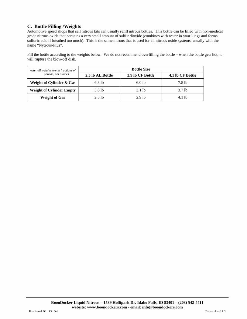
C. Bottle Filling /Weights Automotive speed shops that sell nitrous kits can usually refill nitrous bottles. This bottle can be filled with non-medical grade nitrous oxide that contains a very small amount of sulfur dioxide (combines with water in your lungs and forms sulfuric acid if breathed too much). This is the same nitrous that is used for all nitrous oxide systems, usually with the name “Nytrous-Plus”. Fill the bottle according to the weights below. We do not recommend overfilling the bottle – when the bottle gets hot, it will rupture the blow-off disk.
Bottle Size note: all weights are in fractions of pounds, not ounces 2.5 lb AL Bottle 2.9 lb CF Bottle 4.1 lb CF Bottle
Weight of Cylinder & Gas 6.3 lb 6.0 lb 7.8 lb
Weight of Cylinder Empty 3.8 lb 3.1 lb 3.7 lb
Weight of Gas 2.5 lb 2.9 lb 4.1 lb
BoonDocker Liquid Nitrous – 1589 Hollipark Dr. Idaho Falls, ID 83401 – (208) 542-4411
website: www.boondockers.com - email: [email protected] Revised 01-13-04 Page 5 of 12
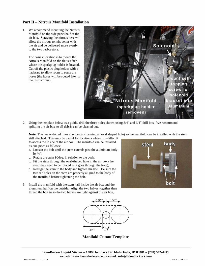
Part II – Nitrous Manifold Installation 1. We recommend mounting the Nitrous
Manifold on the side panel half of the air box. Spraying the nitrous here will allow the nitrous to mix better with the air and be delivered more evenly to the two carburetors.
The easiest location is to mount the Nitrous Manifold on the flat surface where the sparkplug holder is located. Cut off the plastic plug holder with a hacksaw to allow room to route the hoses (the hoses will be routed later in the instructions).
2. Using the template below as a guide, drill the three holes shown using 3/4” and 1/4” drill bits. We recommend
splitting the air box so all debris can be cleaned out.
Note: The heavy dotted lines may be cut (forming an oval shaped hole) so the manifold can be installed with the stem still attached. This may be useful for locations where it is difficult to access the inside of the air box. The manifold can be installed as one piece as follows: a. Loosen the bolt until the stem extends past the aluminum body
by ¼”. b. Rotate the stem 90deg. in relation to the body. c. Fit the stem through the oval-shaped hole in the air box (the
stem may need to be rotated as it goes through the hole), d. Realign the stem to the body and tighten the bolt. Be sure the
two ¾” holes on the stem are properly aligned to the body of the manifold before tightening the bolt.
3. Install the manifold with the stem half inside the air box and the
aluminum half on the outside. Align the two halves together then thread the bolt in so the two halves are tight against the air box.
Manifold Cutout Template
Solenoid
Nitrous Manifold (sparkplug holder
removed)
mount self-tapping
screw for solenoid
bracket into aluminum
0.57” 0.57”
3/4” 1/4”
BoonDocker Liquid Nitrous – 1589 Hollipark Dr. Idaho Falls, ID 83401 – (208) 542-4411
website: www.boondockers.com - email: [email protected] Revised 01-13-04 Page 6 of 12
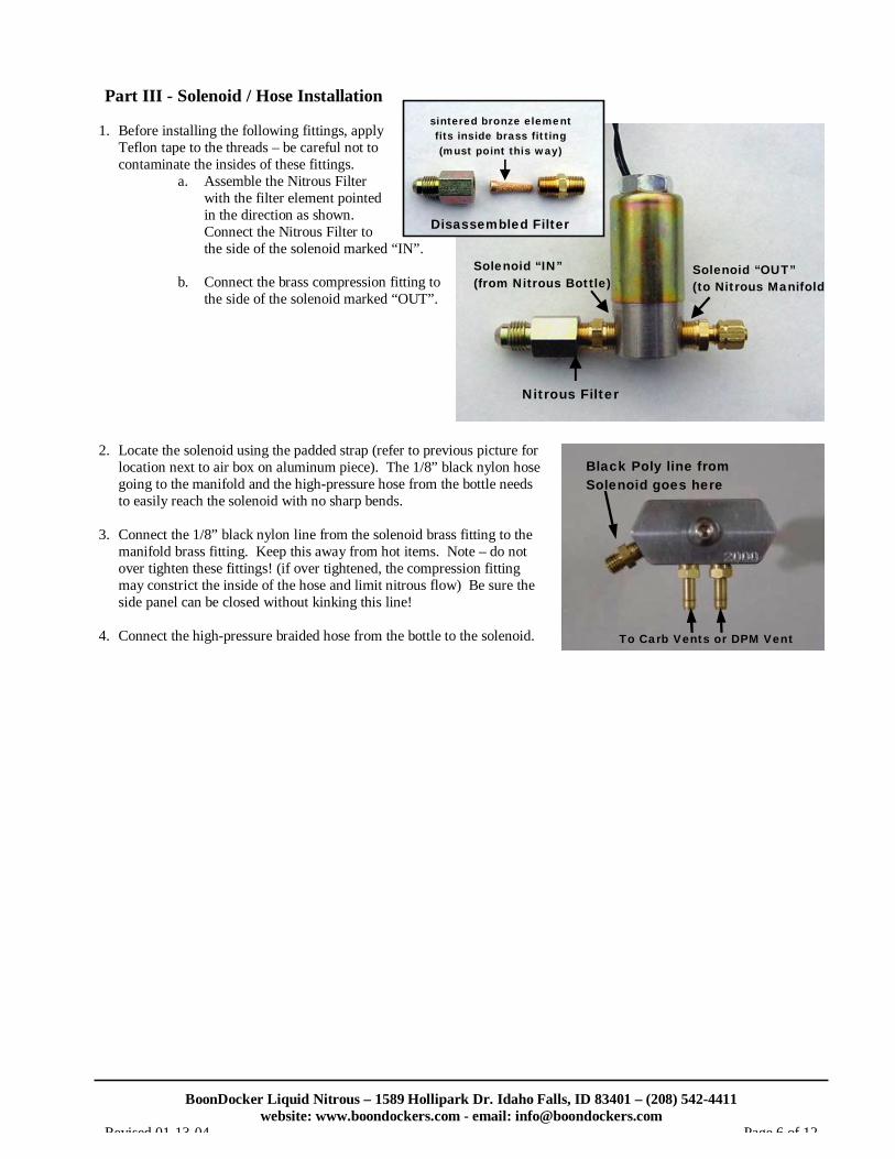
Part III - Solenoid / Hose Installation 1. Before installing the following fittings, apply
Teflon tape to the threads – be careful not to contaminate the insides of these fittings.
a. Assemble the Nitrous Filter with the filter element pointed in the direction as shown. Connect the Nitrous Filter to the side of the solenoid marked “IN”.
b. Connect the brass compression fitting to
the side of the solenoid marked “OUT”. 2. Locate the solenoid using the padded strap (refer to previous picture for
location next to air box on aluminum piece). The 1/8” black nylon hose going to the manifold and the high-pressure hose from the bottle needs to easily reach the solenoid with no sharp bends.
3. Connect the 1/8” black nylon line from the solenoid brass fitting to the
manifold brass fitting. Keep this away from hot items. Note – do not over tighten these fittings! (if over tightened, the compression fitting may constrict the inside of the hose and limit nitrous flow) Be sure the side panel can be closed without kinking this line!
4. Connect the high-pressure braided hose from the bottle to the solenoid.
Nitrous Filter
Solenoid “IN” (from Nitrous Bottle)
Solenoid “OUT” (to Nitrous Manifold)
Disassembled Filter
sintered bronze element fits inside brass fitting (must point this way)
Black Poly line from Solenoid goes here
To Carb Vents or DPM Vent

BoonDocker Liquid Nitrous – 1589 Hollipark Dr. Idaho Falls, ID 83401 – (208) 542-4411
website: www.boondockers.com - email: [email protected] Revised 01-13-04 Page 7 of 12
Part IV - Carb Vent to Nitrous Manifold Installation The nitrous manifold must be able to pressurize the carb float bowl. A. DPM is not used: (refer to the diagram)
Connect the carb vent lines to the nitrous manifold as shown below. Insert a plastic Tee in each line and connect the two vent lines together as shown. The vent lines may need to be lengthened in order to reach the Nitrous Manifold.
B. DPM is used: (refer to the picture and diagram below)
1. Disconnect the DPM vent line from the air box and insert the plastic ¼” barbed Tee.
2. Connect the Plastic Vacuum Check Valve so it is in-line between the original DPM vent on the air box and the ¼” Tee. Be sure the check valve allows air to flow towards the DPM from the air box (White end towards air box vent, Black end points towards DPM). Double check that the check valve flows the right direction by blowing on it both directions. If the check valve is backwards, you will be too lean on nitrous!
3. Connect a 3/16” length of hose from each barbed fitting on the Nitrous Manifold. Tee these together with a
plastic 3/16” Tee, then connect from the other side of this Tee to the ¼” Tee (the 3/16” tubing may need to be stretched to fit on the ¼” barbed Tee).
*Note: Be sure the hoses do not get kinked when the side panel is shut!
Connect Carb vents to Nitrous Manifold
carb carb
Insert Tees and connect vent lines together
carb vents remain connected to DPM
carb carb
DPM
Air box (sidepanel half)
Nitrous Manifold
vacuum check valve must flow in direction towards DPM
Tee
DPM vent
Tee
Vent from DPM
1/4" Tee
Check Valve (white towards airbox, black towards Tee)
3/16" Tee
original DPM airbox vent

BoonDocker Liquid Nitrous – 1589 Hollipark Dr. Idaho Falls, ID 83401 – (208) 542-4411
website: www.boondockers.com - email: [email protected] Revised 01-13-04 Page 8 of 12
Part V – Push-Button Installation The pushbutton switch can be installed on the left handgrip. Shown are directions for installing the button on the left so the button can be pressed with the thumb. There are two clamps in the kit. The one with the screw is only useful if the button needs to be mounted directly to the handlebar. Directions for mounting the button directly to the handgrip using the crimp-on clamp are shown below: 1. Using pliers, bend a hook into one end of the clamp. 2. Connect the clamp to the button as shown. Fit the hooked part of the clamp to the
button so the straight part of the clamp is not connected. 3. Put the button on the left handlebar. With a pen, mark on the clamp where the
mounting hole on the button and the clamp meet. 4. Remove the clamp and cut it approximately ¼” to 3/8” away from the mark. Bend this
end with pliers so it is similar to the other hooked end. 5. Put the button and clamp back on the handlebar. Tighten the clamp with side cutters
so it is just snug. Do not over tighten. 6. The button should appear as shown in the picture.
BoonDocker Liquid Nitrous – 1589 Hollipark Dr. Idaho Falls, ID 83401 – (208) 542-4411
website: www.boondockers.com - email: [email protected] Revised 01-13-04 Page 9 of 12
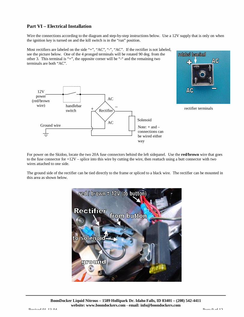
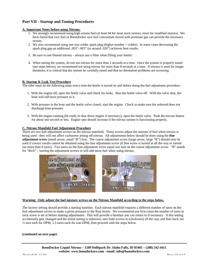
Part VI – Electrical Installation Wire the connections according to the diagram and step-by-step instructions below. Use a 12V supply that is only on when the ignition key is turned on and the kill switch is in the “run” position. Most rectifiers are labeled on the side “+”, “AC”, “-”, “AC”. If the rectifier is not labeled, see the picture below. One of the 4 pronged terminals will be rotated 90 deg. from the other 3. This terminal is “+”, the opposite corner will be “-“ and the remaining two terminals are both “AC”. For power on the Skidoo, locate the two 20A fuse connectors behind the left sidepanel. Use the red/brown wire that goes to the fuse connector for +12V – splice into this wire by cutting the wire, then reattach using a butt connector with two wires attached to one side. The ground side of the rectifier can be tied directly to the frame or spliced to a black wire. The rectifier can be mounted in this area as shown below.
AC
AC
+ _
Solenoid
handlebar switch
12V power
(red/brown wire)
Rectifier
Note: + and – connections can be wired either way
Ground wire
rectifier terminals
BoonDocker Liquid Nitrous – 1589 Hollipark Dr. Idaho Falls, ID 83401 – (208) 542-4411
website: www.boondockers.com - email: [email protected] Revised 01-13-04 Page 10 of 12
Part VII - Startup and Tuning Procedures A. Important Notes before using Nitrous:
1. We strongly recommend using high-octane fuel (at least 94 for most stock motors, more for modified motors). We have found that race fuel or Boondocker race fuel concentrate mixed with premium gas can provide the necessary octane.
2. We also recommend using one size colder spark plug (higher number = colder). In some cases decreasing the spark plug gap an additional .003”-.005” (to around .020”) achieves best results.
3. Be sure to use filtered nitrous – always use a filter when filling your bottle! 4. When tuning the system, do not use nitrous for more than 2 seconds at a time. Once the system is properly tuned
(see steps below), we recommend not using nitrous for more than 8 seconds at a time. If nitrous is used for longer durations, it is critical that the system be carefully tuned and that no detonation problems are occurring.
B. Startup & Leak Test Procedure The rider must do the following steps every time the bottle is turned on and before doing the fuel adjustment procedure.
1. With the engine off, open the bottle valve and check for leaks. Shut the bottle valve off. With the valve shut, the hose will still have pressure in it.
2. With pressure in the hose and the bottle valve closed, start the engine. Check to make sure the solenoid does not discharge hose pressure.
3. With the engine running (be ready to shut down engine if necessary), open the bottle valve. Push the nitrous button for about one second or less. Engine rpm should increase if the nitrous system is functioning properly.
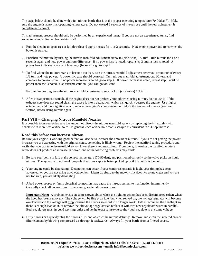
C. Nitrous Manifold Fuel Adjustment Procedure There are two fuel adjustment screws on the nitrous manifold. These screws adjust the amount of fuel when nitrous is being used - they will not affect carburetor jetting off nitrous. All adjustments below should be done using the fine adjustment screw (small arrow, small “R”) first. The coarse adjustment screw (large arrow, large “R”) should only be used if correct results cannot be obtained using the fine adjustment screw (if fine screw is turned in all the way or turned out more than 6 turns). Two turns on the fine adjustment screw equal one turn on the coarse adjustment screw. “R” stands for “Rich” – turning the adjustment screws in will add more fuel when using nitrous. Warning: Only adjust the fuel mixture screws on the Nitrous Manifold according to the steps below. The factory setting should provide a starting baseline. Each nitrous manifold requires a different number of turns on the fuel adjustment screws to make a given pressure to the float bowls. We recommend you first count the number of turns in each screw is set at before making adjustments. This will provide a baseline you can return to if necessary. If this setting accidentally gets changed and the initial setting is unknown, turn both screws in (clockwise) all the way and then back out ½ turn each for DPM, 1.5 turns each for non-DPM, then proceed with the steps below. (continued on next page)
BoonDocker Liquid Nitrous – 1589 Hollipark Dr. Idaho Falls, ID 83401 – (208) 542-4411
website: www.boondockers.com - email: [email protected] Revised 01-13-04 Page 11 of 12
The steps below should be done with a full nitrous bottle that is at the proper operating temperature (70-90deg F). Make sure the engine is at normal operating temperature. Do not exceed 2 seconds of nitrous use until the fuel adjustment is complete and correct. This adjustment process should only be performed by an experienced tuner. If you are not an experienced tuner, find someone who is. Remember, safety first! 1. Run the sled in an open area at full throttle and apply nitrous for 1 or 2 seconds. Note engine power and rpms when the
button is pushed. 2. Enrichen the mixture by turning the nitrous manifold adjustment screw in (clockwise) 1/2 turn. Run nitrous for 1 or 2
seconds again and note power and rpm difference. If no power loss is noted, repeat step 2 until a loss is noted. A power loss indicates you are rich enough (be sure!) - go to step 3.
3. To find where the mixture starts to become too lean, turn the nitrous manifold adjustment screw out (counterclockwise)
1/2 turn and note power. A power increase should be noted. Turn nitrous manifold adjustment out 1/2 turn and compare to previous run. If no power increase is noted, go to step 4. If power increase is noted, repeat step 3 until no power increase is noted. Use extreme caution - you can go too lean!
4. For the final setting, turn the nitrous manifold adjustment screw back in (clockwise) 1/2 turn. 5. After this adjustment is made, if the engine does not run perfectly smooth when using nitrous, do not use it! If the
exhaust note does not sound clean, the cause is likely detonation, which can quickly destroy the engine. Use higher octane fuel, add more ignition retard, reduce the engine’s compression, or reduce the amount of nitrous (see next section) before using nitrous again.
Part VIII – Changing Nitrous Manifold Nozzles It is possible to increase/decrease the amount of nitrous the nitrous manifold sprays by replacing the ¾” nozzles with nozzles with more/less orifice holes. In general, each orifice hole that is sprayed is equivalent to a 3-5hp increase. Read this before you increase nitrous! Be sure your engine is working good before you decide to increase the amount of nitrous. If you are not getting the power increase you are expecting with the original setup, something is likely wrong. Review the manifold tuning procedure and verify that you can tune the manifold so you know there is too much fuel. From there, if leaning the manifold mixture screw does not produce an increase in power, one of the following problems may exist: 1. Be sure your bottle is full, at the correct temperature (70-90 deg), and positioned correctly so the valve picks up liquid
nitrous. The system will not work properly if nitrous vapor is being picked up or if the bottle is too cold. 2. Your engine could be detonating. Detonation can occur if your compression ratio is high, your timing has been
advanced, or you are not using good octane fuel. Listen carefully to the motor - if it does not sound clean and you are not too rich, you are likely detonating.
3. A bad power source or faulty electrical connection may cause the nitrous system to malfunction intermittently.
Carefully check all connections. If necessary, solder all connections. Important Note: A problem exists on some snowmobiles when the lighting system has been disconnected (often when the hood has been removed). The voltage will be fine at an idle, but when revved up, the voltage regulator will become overloaded and the voltage will drop, causing the nitrous solenoid to no longer work. Either reconnect the headlight so there is enough load on it, or remove the old voltage regulator an replace it with two new regulators wired in parallel. Both regulators must in good working order and be the exact same type so they both regulate to the same voltage.
4. Dirty nitrous can quickly plug the nitrous filter and obstruct the nitrous delivery. Remove and clean the sintered bronze
filter element by blowing compressed air through it backwards. Always fill your bottle from a filtered source.

BoonDocker Liquid Nitrous – 1589 Hollipark Dr. Idaho Falls, ID 83401 – (208) 542-4411
website: www.boondockers.com - email: [email protected] Revised 01-13-04 Page 12 of 12
Installing / Removing Nozzles 1. Remove the nitrous manifold from the air box. 2. Use a 7/32” hex wrench to carefully remove/install a
nozzle. Be sure the o-ring is still in place before threading in a new nozzle. Be very careful not to over tighten the plastic nozzle – it needs to be just snug.
3. If you want to increase nitrous delivery, increase the
total number of nozzle holes by one! (ie. go from 7 holes to 8 holes)
4. Retune the nitrous manifold according to the
instructions above. Anytime the orifices are changed, the nitrous manifold pressure will change so retuning is necessary.
Part IX – Warranty, Terms & Conditions Returned Goods – No merchandise will be accepted without prior approval. A RMA number (Return Merchandise Authorization) provided by Boondocker is required before a return will be accepted. A 20% handling and restocking charge will be applied to returned merchandise. No unauthorized returns will be accepted. Limited Warranty – Boondocker warrants its product to the original purchaser against workmanship defects for a period of 90 days, commencing from the date of product delivery to the Consumer. Maximum Liability – The maximum liability of Boondocker in connection with this warranty shall not under any circumstances exceed the price of the product claimed to be defective.
o-ring
nozzle