boogie board manual - erthenvarerthenvar.com/store/download/boogie_board_user_guide.pdf · the...
TRANSCRIPT

BOOGIE BOARDFLATPACK EURORACK
User GuidePreliminary

TABLE OF CONTENTSŸ Table of Contents 2
Ÿ Flatpack Eurorack? 3
Ÿ The Boogie Board 4
Ÿ Magic Bus! 5
Ÿ In The Box 6
Ÿ Is This The Case For Me? 7
Ÿ Example Imperfections 8
Ÿ Technical Specifications 9
Ÿ Instructions 10-16
Ÿ Power Up 17
Ÿ Tips 18

Flatpack Eurorack is our series of low-cost, customizable Eurorack (3U) and Tile (1U) modular synthesizer cases.
Flatpack Eurorack ships as ready-to-assemble kit containing everything you need, much like a piece of Swedish furniture.
In addition, Flatpack Eurorack was designed to fit in a USPS Priority Mail Flat Rate box. This means it can be shipped across the USA at a reasonable price, despite the aluminum and wood included.
The Flatpack Eurorack series houses both the Eurorack 3U format of modules, in addition to our Tile 1U format.
If you aren’t familiar with our Tile line, these utility modules are tiny in size (most are 6 hp wide) and are designed to supplement Eurorack systems, especially smaller setups.
Use Tiles to add utilitarian function without using precious Eurorack hp. Want to send a signal to multiple destinations? Add a Mult. Tame a module with no input attenuators with an Att-Vert attenuverter. Want tactile modulation? Have an FSR.
FLATPACK EURORACK?

You have some idea of our design philosophy behind the Eurorack Flatpack series, now how about some details?
The first Flatpack Eurorack is called Boogie Board. As mentioned, it houses both Euro and Tile modules, to the tune of 60 hp (10 Tile Units). Maximum depth is a deeper-than-skiff 95 mm.
The case is a fully-enclosed box, there are no exposed boards or cables hanging out of the back. The box itself is laser cut and engraved Baltic Birch 1/4” 5-ply wood.
This high-quality wood is sourced at a local lumber yard and is nicer than common plywood. It is pretty, especially once charred by the laser, and has a good strength/weight ratio.
Also included are two pairs of V-Rails, 60 hp (12”) in length. One pair forms the rack for the Euro modules, the other for Tiles. Our M2.5 Square Rail Nuts are loaded into the rails and M2.5 Stainless Steel Phillips 6 mm screws hold the modules in.
M2.5 Square Rail Nuts are also used to hold the case together coupled with M2.5 Stainless Steel 12 mm screws. Details are in the assembly section.
The rails are mounted to a pair of our 3U+1U aluminum brackets, which not only help square everything up, they also provide structural integrity.
THE BOOGIE BOARD.
So, included is a wooden case, rails, hardware. What about power?
Don’t worry, we’ ve got you covered! Included in the kit is our brand new powered bus board, Magic Bus.
What makes it Magic? The Magic Bus features a DC input voltage range of 9-18V. That makes it easy to power with an external battery, allowing the Boogie Board to be a truly portable modular synthesizer.
There are 10x 16-pin shrouded headers for powering Euro modules. The convention is -12V toward the front of the case, with the two horizontal headers having -12V toward the right. If you need help confirming power orientation of your modules, please don’t hesitate to email us.
There are a total of 16x 3-pin Tile power connectors. There are 8x with 15 cm length toward the front of the case, and 8x with 30 cm cables toward the rear of the case.
The Magic Bus is good for up to 1 Amp on the +/-12 V rails and has trimmers for calibrating the power rails to your setup. It is calibrated at the factory for a load of 400 mA on each rail.
There is no on board +5 V regulation, but add a Freelunch for up to 600 mA.
MAGIC BUS!
CaseŸ 1x wooden case (5 pieces: bottom, front, back, left, right)Ÿ 1x scrap piece of wood for testing finishes
MountingŸ 2x pairs of 60 hp V-Rails (4 rails total)Ÿ 2x 3U+1U mounting brackets (left, right)
HardwareŸ 100x M2.5 Square Rail Nuts (24 for case, 40 for Tiles, 36 for Euro)Ÿ 100x M2.5 x 6 mm Stainless Steel Phillips Screws (for Euro/Tiles)Ÿ 18x M2.5 x 12 mm Stainless Steel Phillips Screws (for case)Ÿ 8x #10-24 3/4” Zinc Phillips Screws (for rails)Ÿ 8x #10-24 3/8” 3/32” Hex Black Oxide Set Screws (for rails)Ÿ 4x #6-32 1/2” Zinc Phillips Screws (for brackets)Ÿ 4x #6-32 Stainless Steel Cap Nuts (for brackets)Ÿ 4x 3/8" x 5/32" rubber feetŸ 4x 3/8" x 7/32" rubber feet
PowerŸ 1x Magic Bus powered bus boardŸ 1x 110-240 VAC input, 12 VDC 3 A output line lumpŸ 4x 15 cm Tile Splitters (to power Tiles, attached to bus board)Ÿ 4x 30cm Tile Splitters (to power Tiles, attached to bus board)Ÿ 1x 5.5 x 2.1 mm DC barrel jack with nut (attached to bus board)
IN THE BOX
We set out to create a low-cost case that would work for both modular newbies and pros alike. We didn’t want to compromise on the heart of the system: power.
The Boogie Board is an easy entry-level project. There is no drilling, sawing, gluing, soldering, or other difficult steps. The only tools you need are a small Phillips screwdriver and an allen key.
The case itself ships as raw, laser cut plywood. They are precision cut which makes everything line up and fit nicely.
However, the wood is unfinished. It can be left that way and will make a usable, rustic case. But, with some imagination, elbow grease, and some sand paper, paint, or stain, you can completely customize it!
Despite cutting nice quality wood on a high powered laser, the cases are not flawless. Gaps, knots, and glue variation create some cosmetic issues on the bottom of the cut (inside of the case).
These kind of flaws would normally be taken care of by sanding and finishing, but we do not process the wood after cutting.
We inspect each case before it ships to make sure it meets our quality standards. Please see pictures of imperfections in shipping cases on the following page to see if the Boogie Board is the right case for you.
IS THIS THE CASE FOR ME?

EXAMPLE IMPERFECTIONS
Plywood gap and laser cut imperfections cause by gap (top, inside)
Chipping caused by incomplete cut (bottom, inside)
Incomplete cut caused chipping (side, inside)
Laser floor texture engraved into wood (side, inside)
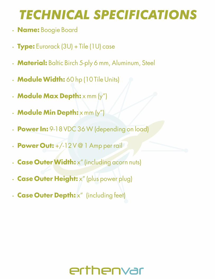
Ÿ Name: Boogie Board
Ÿ Type: Eurorack (3U) + Tile (1U) case
Ÿ Material: Baltic Birch 5-ply 6 mm, Aluminum, Steel
Ÿ Module Width: 60 hp (10 Tile Units)
Ÿ Module Max Depth: x mm (y”)
Ÿ Module Min Depth: x mm (y”)
Ÿ Power In: 9-18 VDC 36 W (depending on load)
Ÿ Power Out: +/-12 V @ 1 Amp per rail
Ÿ Case Outer Width: x” (including acorn nuts)
Ÿ Case Outer Height: x” (plus power plug)
Ÿ Case Outer Depth: x” (including feet)
TECHNICAL SPECIFICATIONS

Step 1: Find a clean work surface and unpack the Boogie Board kit
Step 2: Lay the 4 rails horizontally and stand them on the narrow side. Space them according to the picture, and point the channels inward so those in the 3U section face each other, and the 1U face each other
INSTRUCTIONS
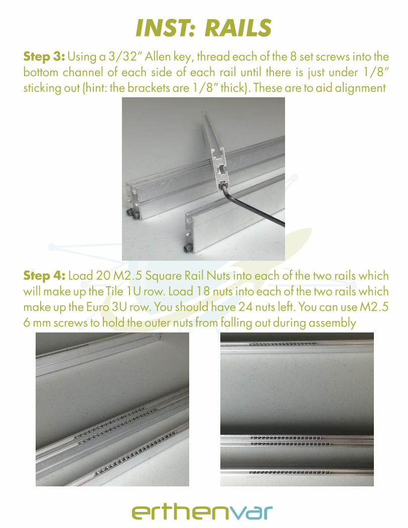
Step 3: Using a 3/32” Allen key, thread each of the 8 set screws into the bottom channel of each side of each rail until there is just under 1/8” sticking out (hint: the brackets are 1/8” thick). These are to aid alignment
Step 4: Load 20 M2.5 Square Rail Nuts into each of the two rails which will make up the Tile 1U row. Load 18 nuts into each of the two rails which make up the Euro 3U row. You should have 24 nuts left. You can use M2.5 6 mm screws to hold the outer nuts from falling out during assembly
INST: RAILS
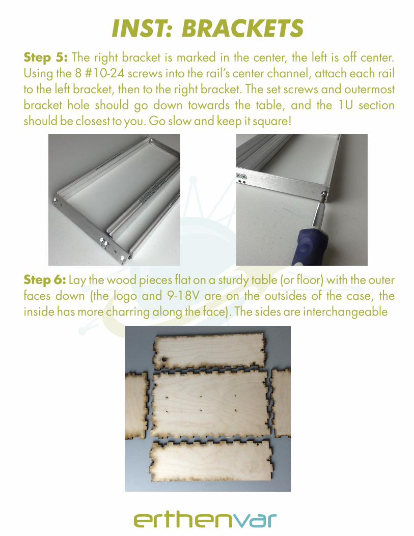
Step 5: The right bracket is marked in the center, the left is off center. Using the 8 #10-24 screws into the rail’s center channel, attach each rail to the left bracket, then to the right bracket. The set screws and outermost bracket hole should go down towards the table, and the 1U section should be closest to you. Go slow and keep it square!
Step 6: Lay the wood pieces flat on a sturdy table (or floor) with the outer faces down (the logo and 9-18V are on the outsides of the case, the inside has more charring along the face). The sides are interchangeable
INST: BRACKETS

Step 7: Slide each piece on to the bottom, starting with the right followed by the front, back, and left. Try and push the pieces on upright (rather than flat and hinging them upward). The pieces will interlock and form a box
Step 8: Take 12 M2.5 12 mm screws, and thread them on 12 Square Rail Nuts until the screw just pokes through the other side. Slide the assemblies into each of the 12 holes around the case (4 each on left, right, and bottom) and tighten with a small Phillips screw driver. Do NOT over tighten
INST: WOODEN CASE

Step 9: Flip the box upside down, take the remaining 6 M2.5 12mm screws, and place them through the bottom of the case. On the inside of the case, tighten a Square Rail Nut on each screw
Step 10: Flip the box over and place the Magic Bus on to the 6 screws. The DC barrel jack should be to the left and the Euro headers to the right. Put a Square Rail Nut on the 6 screws. Push the DC barrel jack through the hole and twist the nut on the outside of the case
INST: MAGIC BUS

Step 11: Take the rail/bracket frame, and place it into the wooden box. The set screws should face down and the Tile row should be in front. Line up the bracket and wooden case holes, and place a #6-32 screw from the inside through each hole
Step 12: Tighten a #6-32 cap nut on on each screw using a Phillips screw driver on the inside and fingers outside. Take care not to smudge the case around the nuts while you hold them
INST: ASSEMBLY

Step 13: Place rubber feet on the 4 corners of the bottom of the case. Included are two thicknesses of feet. If your case does not sit flat on your desk, swap the taller feet in to the corners that are rocking
Step ?: Don’t forget to plan your sanding, staining, and/or painting. Some may prefer to do this as step 1, others as step 14. We recommend removing all metal hardware during finishing. Included is a piece of scrap wood for testing finishes
INST: FINISHING
By now, it’s time to power up your Boogie Board for the first time. Although the Magic Bus is tested at the factory, we recommend powering up before you install your modules.
Take the line lump, plug in the IEC adapter, and plug it into the wall outlet. Then, plug the 5.5 x 2.1 mm tip into the rear of the Boogie Board. In total, 3 amber LEDs should light.
The LED on the far left indicates that input power is present. The top LED in the center indicates that the +12 V rail is active, and the bottom LED in the center indicates that the -12V rail is active. For proper operation, all 3 should be lit.
Ÿ Take care to note the power polarity of your Euro (and Tile) modules
Ÿ Use power estimation tools to figure out how much current you’re using
Ÿ It is unlikely to over-current or over-heat the 60 hp Boogie Board
Ÿ High current applications should pay mind to case temperatures
Ÿ In the event of a power reversal, over-current, or over-heat, the output voltage will drop, and the Magic Bus will let out an audible whine. Unplug the Boogie Board immediately, and investigate the cause
POWER UP!

Ÿ You can touch up blemishes on the charred sides with a dark walnut colored stain (they sell stain pens for around $6) or a black Sharpe
Ÿ The Boogie Board may be disassembled in order for servicing, b ut it is not recommended to take it apart frequently
TIPS