bollettino tecnico technical bulletin · pdf filebollettino tecnico technical bulletin...
TRANSCRIPT

BOLLETTINO TECNICO
TECHNICAL BULLETIN
TECHNISCHE MITTEILUNGEN
BT 008CONNESSIONI ELETTRICHE
ELECTRICAL CONNECTION
ELEKTRISCHE ANSCHLÜSSE

2
Indice / Table of contents / Index / Inhaltsverzeichnis
Sommario / Summary / Inhaltsangabe pag 3
Generalità / Generality / Allgemeines pag 3
Compressori serie H1 monofase / H1 range single phase / Verdichter der H1-Serie einphasig pag 4
compressori serie H1 trifase e SCC / H1 and SCC_1 range three phases / Verdichter der H1-Serie dreiphasig und scc_1 pag 6
compressori serie H2-H32-H34-H54 e SCC_ 32 / H2-H32-H34-H35 and SCC_32 compressor ranges / Verdichter der Serien h2-h32-h34-h35 und scc_32 pag 7
collegamento PWS / PWS connection / PWS-Anschluss pag 7
compressori serie H4-H41-H5-H6-H7 e SCC_4-CD / H4-H41-H5-H6-H7 and SCC4-CD compressor range / Verdichter der Serien H4-H41-H5-H6-H7 und SCC_4 CD pag 12
Modalità di collegamento / Connection mode / Anschlussart pag 13
Indice / Table of contents / Inhaltsverzeichnis

3
Indice / Table of contents / Index / Inhaltsverzeichnis
Vol. Spost.DisplacementVolume bal.
Fördervolumen
[m 3/h]
H40CC 2,89
H50CS 3,86
H75CC 3,86H75CS 5,30
H100CC 5,30H100CS 6,75
H150CC 6,75H150CS 7,71
H180CC 7,71H180CS 8,47
H200CC 8,47H200CS 9,88H220CC 9,88
H220CS 10,85H250CC 10,85
H250CS 12,17H280CC 12,17
H280SB 13,23H280CS 13,23
H290CS 14,74
H300CC 14,74
H300CS 15,94H350CC 15,94
H350SB 17,53H380CC 17,53
H380SB 19,53H390CS 19,53
H392CS 23,31
H403CC 19,98H403CS 22,83
H503CC 22,83
H503CS 26,44H743CC 26,44
H401CS 19,29
H451CC 19,29H451CS 23,13
H551CC 23,13H551CS 27,33
H701CC 27,33H701CS 31,88
H751CC 31,88H751CS 38,06
H801CC 38,06
H851CS 42,81H1001CC 42,81H1001CS 48,82
H1501CC 48,82H1501CS 56,87
H2001CC 56,87H1601CS 63,76
H2201CC 63,76
SerieRangeSerieSerie
ModelloModel
ModèleTyp
H35
H1
H41
H32
H2
Vol. Spost.DisplacementVolume bal.
Fördervolumen
[m 3/h]
H2000CS 75,83
H2500CC 75,83
H2500CS 85,01H3000CC 85,01
H2700CS 92,25H3200CC 92,25
H2900CS 102,35H3400CC 102,35
H3000CS 113,74
H3500CC 113,74H3500CS 127,52
H4000CC 127,52
H4000CS 138,37H4500CC 138,37
H4500CS 153,52H5000CC 153,52
H5000CS 164,30
H5500CC 164,30H5500CS 184,19
H6000CC 184,19H6000CS 199,86
H7500CC 199,86H7501CS 221,75H8001CC 221,75
H7
H6
SerieRangeSerieSerie
ModelloModel
ModèleTyp
H5
Vol. Spost.DisplacementVolume bal.
Fördervolumen
[m3/h]
SCC180B 2.89
SCC250B 3.86
SCC300B 5.3SCC350B 6.75
SCC380B 8.47
SCC500B 13.15SCC750B 16.43
SCC1500B 25.5
SCC1900B 32.5
SCC2000B 38.7SCC2500B 48.8
SCC 4
SCC 32
SerieRangeSerieSerie
ModelloModel
ModèleTyp
SCC 1
Vol. Spost.DisplacementVolume bal.
Fördervolumen
[m 3/h]
CD 150M 1,12
CD 180H 1,12
CD 180M 1,46CD 300H 1,46
CD 300M 1,88CD 350H 1,88
CD 350M 2,39CD 360H 2,39
CD 360M 3,00CD 380H 3,00
CD 380M 3,59
CD 380B 4,50
CD 700H 4,34CD 700M 4,74
CD 750H 4,74CD 750M 5,61
CD 1000H 5,61CD 750B 6,92CD 1000M 6,92CD 1200H 6,92
CD 800B 8,92
CD 1100M 8,92CD 1300H 8,92
CD 1300M 10,12CD 1500H 10,12
CD 1000B 11,62CD 1400M 11,62
CD 1900H 11,62
CD 1200M 9,48CD 1400H 9,48
CD 1500M 11,69
CD 2000H 11,69CD 1200B 13,84CD 2000M 13,84CD 2400H 13,84
CD 1500B 15,72CD 2500H 15,72
CD 2500M 17,84CD 3000H 17,84
CD 2000B 20,25CD 3000M 20,25
CD 3400H 20,25CD 2500B 23,25
CD 3500H 23,25CD 3000B 26,57CD 3500M 26,57
CD 4000H 26,57
SerieRangeSerieSerie
ModelloModel
ModèleTyp
CD 300 SLING DISK
CD 300 OIL
PUMP
CD 400 SLING DISK
CD 400 OIL
PUMP
CD 200
Sommario
Il presente bollettino tecnico descrive la tipologia dei motori elettrici e le istruzioni di collegamento elettrico per le seguenti gamme di compressori prodotti da Officine Mario Dorin e su tutte le unità condensatrici dove sono installati i compressori riportati in tabella.
Summary
Subject of the present bulletin are electrical motor characteristics and electrical connection of following compressor ranges produced by Officine Mario Dorin and condensing units related to each model.
Inhaltsangabe
Die vorliegende technische Anleitung beschreibt die Elektromotortype und schildert die Anweisungen für den elektrischen Anschluss der folgenden Auswahl an Verdichtern, die von Officine Mario Dorin hergestellt werden, sowie die jeweils entsprechenden Verfluessigungssaetze

4
BT_008
GENERALITA’
Il presente bollettino tecnico descrive i collegamenti elettrici previsti per i compressori prodotti da Officine Mario Dorin sulle seguenti gamme di compressori:Serie HSerie HISerie HEXSerie SCCSerie CDE sulle seguenti unità condensatrici su cui sono installati i compressori semiermetici della serie H:Serie AUSerie AUTSerie AULNSerie AUISerie WUSerie RUIl corretto collegamento elettrico, in funzione della tipologia di motore installato sul compressore e della tensione di rete, ècondizione imprescindibile per il corretto funzionamento del compressore. L’errato collegamento elettrico può portare a cortocircuiti e quindi causare la bruciatura del motore elettrico.Installando il compressore in condizioni difformi rispetto a quelle indicate in questo Bollettino Tecnico, si potranno avere condizioni di lavoro non contemplate nella fase di progetto. Il compressore pertanto non garantirà le prestazioni dichiarate e potrebbe andare incontro a a serio danneggiamento. Nel presente Bollettino Tecnico saranno riportati per i vari modelli e gamme gli schemi elettrici di collegamento.Per informazioni relative a compressori speciali contattare il nostro servizio tecnico-commerciale.
attenzioneSi raccomanda di eseguire i collegamenti elettrici in accordo con gli schemi allegati al presente Bollettino Tecnico, e nel rispetto delle norme di sicurezza in vigore nel luogo di installazione.I collegamenti elettrici devono essere eseguiti esclusivamente da personale specializzato; Dorin non sarà responsabile per alcun motivo di danni a cose o persone derivanti da azioni scorrette effettuate sul compressore.Per i requisiti di sicurezza si deve tenere presente , in fase di installazione del compressore, quanto contenuto e riportato nelle istruzioni d’uso e manutenzione fornite a corredo il compressore.Se il compressore è corredato di resistenza carter questa deve essere collegata separatamente in accordo con quanto indicato nello specifico bollettino tecnico BT_001.
GENERALITY
Present bulletin describes the electrical connection suitable for the following compressor ranges produced by Officine Mario Dorin:H rangeHI rangeHEX rangeSCC rangeCD rangeAnd on condensing units where semihermetic compressors belonging to H range are installed:AU rangeAUT rangeAULN rangeAUI rangeWU rangeRU rangeFor a proper operation electrical machines has to be correctly connected to the main voltage supply depending on both electrical motor and supply voltage at the net. An incorrect connection can cause a short circuit and hence a motor burn out. Any connection that is NOT made in accordance with the following recommendations will not guarantee correct functioning of the compressor nor performance data declared in the catalogue.In this Technical Bulletin you will find all the connection diagrams covering all the compressor ranges.
warningIt is recommended that connections be made in accordance with the diagrams enclosed in this Technical Bulletin and also in compliance with local safety regulations and standards.Connections should only be made by qualified personnel. Dorin will not accept any responsibility for any damage to persons, property or machinery of any kind due to incorrect actions on the compressor.For safety requirements, the instructions for use and maintenance, which are supplied with the compressor, MUST always be followed during compressor installation.If the compressor is fitted with a crankcase heater then this must be connected separately in accordance with the specific technical bulletin BT_001.
ALLGEMEINE HINWEISE
Die vorliegenden technischen Informationen beschreiben die elektrischen Anschlüsse, die folgenden Verdichterserien der Firma Officine Mario Dorin vorgesehen sind:Serie HSerie HISerie HEXSerie SCCSerie CDund die auf den nachfolgend aufgeführten Verflüssigungseinheiten vorgesehen sind, auf denen halbhermetische Verdichter der Serie H installiert sind:Serie AUSerie AUTSerie AULNSerie AUISerie WUSerie RUDer korrekte elektrische Anschluss, je nachdem welcher Motor auf dem Verdichter installierter ist und je nach Netzspannung, ist für ein korrektes Funktionieren des Verdichters von unabdingbarer Wichtigkeit. Der falsche elektrische Anschluss kann zu Kurzschlüssen führen und demzufolge einen Elektromotorbrand verursachen.Sollte der Verdichter nicht konform gemäßden Angaben der vorliegenden technischen Informationen installiert werden, können sich Betriebsbedingungen ergeben, die während der Planung nicht berücksichtigt worden sind. Der Verdichter wird demzufolge nicht die erklärten Leistungen erbringen und könnte schwer beschädigt werden. In den vorliegenden technischen Informationen werden je nach Modell- und Serienart die elektrischen Anschlussschemen angegeben.Sollten Sie Informationen bezüglich Spezial-Verdichter benötigen, setzten Sie sich bitte mit unserem technischen-kommerziellen Service in Verbindung.
AchtungEs ist ratsam die elektrischen Anschlüsse gemäß den Schemen der vorliegenden technischen Informationen und gemäß den Sicherheitsvorschriften auszuführen, die am Installationsort rechtsgültig sind.Die elektrischen Anschlüsse müssen ausschließlich durch fachkundiges Personal ausgeführt werden; die Firma Dorin wird in keinem Fall für Schäden an Sachen oder Personen verantwortlich sein, die auf unsachgemäße Eingriffe auf den Verdichter zurückzuführen sind.Hinsichtlich der Sicherheitsvorkehrungen muss während der Installation des Verdichters den Bedienungs- und Wartungsanleitungen gefolgt werden, die zusammen mit dem Verdichter geliefert werden.Sollte der Verdichter mit einer Ölheizung des Kurbelgehäuses ausgestattet sein, so muss diese getrennt angeschlossen werden, so wie in den spezifischen technischen Informationen BT_001 angegeben.

5
BT_008
COMPRESSORI SERIE H1 MONOFASE
I compressori monofase necessitano di un kit di condensatori e di un relay per funzionare correttamente. A seconda del modello prescelto saranno necessari 1 o 2 o 4 condensatori di spunto, in base alla potenza elettrica del motore. Se si utilizzano due condensatori di spunto, questi dovranno essere collegati in serie, come mostrato nella figure sottostanti.Se si utilizzano 4 condensatori di spunto questi dovranno essere montati in serie a due a due. Le due serie vanno poi collegate in parallelo come illustrato nelle figure sottostantiLe tabelle sottostanti riportano i codici dei kit monofase e le caratteristiche tecniche dei condensatori per ogni compressore.
NB: l’omologazione UL è disponibile per un numero di modelli limitato della gamma H1. Contattare il nostro servizio tecnico per la lista esatta.
H1 RANGE SINGLE PHASE
Single phase compressors require a kit comprising of capacitors and relay in order to operate correctly. Depending on the selected model there will be either one or two or four start capacitors rated for the appropriate motor size. If two start capacitors are used then these must be connected in SERIES, as shown on the following diagrams.If four start capacitors are used then make two groups of two capacitors. Connect each two capacitors in SERIES, then connect the two series in PARALLEL as shown in the following pictures.Following table shows capacitor kit codes and capacitor technical characteristics for each model.The diagrams show the connection requirements for each compressor type.NOTE: UL certification is available only for a limited models of H1 range. For a complete list kindly contact our technical department.
ALIMENTAZIONE A 50 E 60 Hz
SUPPLY VOLTAGE 50 AND 60 Hz
EINSPEISUNG 50 UND 60 Hz
Compressore Condensatori di avvio Condensatori di marcia
KITCompressor Starting capacitor Running capacitor
Verdichter Anlauf-Kondensatoren Betriebskondensatoren
No. [µF] No. [µF]
H40CC÷H75CS 1 160 1 16 1RC8021
H100CC÷H100CS 1 250 1 31,5 1RC8041
H150CC÷H150CS 1 300 1 31,5 1RC8061
H180CC÷H200CS 2 300 1 36 1RC8081
H250CC÷H280CC 4 300 1 40 1RC8221
COMPRESSORI UL 60 Hz
UL COMPRESSORS 60 Hz
UL VERDICHTER 60 Hz
Compressore Condensatori di avvio Condensatori di marcia
KITCompressor Starting capacitor Running capacitor
Verdichter Anlauf-Kondensatoren Betriebskondensatoren
No. [mF] No. [mF]
H100CC
2 300 1 40 1RC8211H150CC
H150CS
H180CC÷H200CS 2 300 1 36 1RC8191
H220CC÷H280CC 4 300 1 40 1RC8231
VERDICHTER DER H1 SERIE EINPHASIG
Die einphasigen Verdichter benötigen ein Kondensatoren-Set und ein Relais, um richtig funktionieren zu können. Je nach ausgewähltem Modell und auf Grund der elektrischen Motorleistung werden 1 oder 2 oder 4 Anlaufverdichter notwendig sein. Wenn zwei Anlaufverdichter verwendet werden, so müssen diese hintereinander geschaltet werden, wie in den nachfolgenden Abbildungen dargestellt.Wenn vier Anlaufverdichter gebraucht werden, so müssen diese paarweise hintereinander geschaltet sein. Die zwei Reihen werden parallel geschaltet, wie in den nachfolgenden Abbildungen dargestellt.In den untenstehenden Tabellen sind die Kode-Nummern der einphasigen Sets angegeben sowie die technischen Eigenschaften der Kondensatoren für jeden einzelnen Verdichter.ANMERKUNG: Die UL-Zulassung steht nur einer beschränkten Anzahl von Modellen der H1 Serie zur Verfügung. Setzen Sie sich mit unserem technischen service in Verbindung, um die genaue Liste zu erfragen.

6
BT_008
SCHEMA COLLEGAMENTO ELETTRICO ELECTRICAL CONNECTION ELEKTRISCHES VERBINDUNGSSCHEMA
Schema di collegamento elettrico con 1 o 2 condensatori di spunto
Electrical connection scheme with 1 or 2 start capacitors
Schema der elektrischen Anschlüsse mit 1 oder 2 Anlauf Verdichtern
Schema di collegamento elettrico con 4 condensatori di spunto
Electrical connection scheme with 4 start capacitors
Schema der elektrischen Anschlüsse mit 4 Anlauf Verdichtern
SC1-SC2SC3-SC4
condensatore di spunto
marrone-brown
marrone
start capacitor brown
Anlauf Kondensator braun
RC
condensatore di marcia
nero-black
nero
run capacitor black
Betriebskondensator schwarz
L
linea
grigio-grey
grigio
line grey
Leitung grau
N
neutro
U1-V1-W1U2-V2-W2
passanti filettati
neutral threaded pins
neutral Durchführungen mit Gewinde
terra
1-2
protezione termica
ground thermal protection
Erde Thermoschutzeinrichtung

7
BT_008
COMPRESSORI SERIE H1 TRIFASE E SCC_1
La seguente tabella illustra le tipologie di motore disponibili sui compressori della gamma H1.NB: l’omologazione UL è disponibile per un numero di modelli limitato della gamma H1. Contattare il nostro servizio tecnico per la lista esatta.
H1 AND SCC_1 RANGE THREE PHASES
Following table shows all the motors available on the H1 compressor rangeNOTE: UL certification is available only for a limited models of H1 range. For a complete list kindly contact our technical department.
VERDICHTER DER H1 SERIE DREIPHASIG UND SCC_1
Die folgende Tabelle zeigt die zur Verfügung stehenden Motorentypen der Verdichter der H1 Serie. ANMERKUNG: Die UL-Zulassung steht nur einer beschränkten Anzahl von Modellen der H1-Serie zur Verfügung. Setzen Sie sich mit unserem technischen Service in Verbindung um die genaue Liste zu erfragen.
Y
collegamento a stella
1-2
protezione termica
star connection thermal protection
Stern-Aschluss Thermoschutzvorrichtung
∆
collegamento a triangolo
L1-L2-L3
linea
delta connection line
Dreieck Aschluss Leitung
collegamento a terra
U1-V1-W1U2-V2-W2
passanti
ground connection connection pins
Erdanschluß Verbindungen/Durchführungen
Schema di collegamento elettrico stella/triangolo gamme H1-SCC _1
Star / delata electrical connection scheme H1-SCC_1
Schema der elektrischen Stern/Dreieck Anschlüsse für die Seri en H1-SCC_1
H1
MOTORE ALIMENTAZIONE COLLEGAMENTO
MOTORE SUPPLY VOLTAGE CONNECTION
MOTOR EINSPEISUNG VERBINDUNG
STANDARD380-420 50 Hz / 440-480 60 Hz Υ
220-240 50 Hz / 265-290 60 Hz ∆
60 Hz380-420 Υ
220-240 ∆
200 50-60 Hz 200 50 Hz or 200 60 Hz ∆
UL 208-230/3/60 ∆
8
BT_008
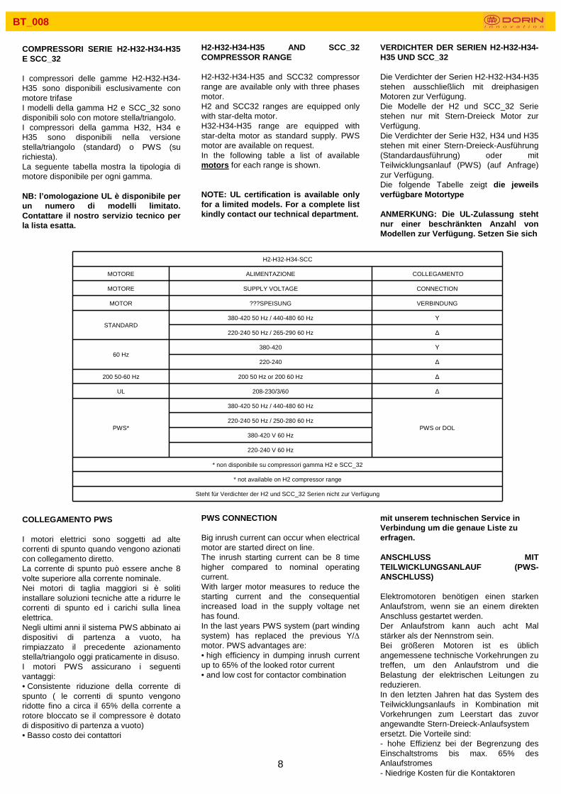
COMPRESSORI SERIE H2-H32-H34-H35 E SCC_32
I compressori delle gamme H2-H32-H34-H35 sono disponibili esclusivamente con motore trifase I modelli della gamma H2 e SCC_32 sono disponibili solo con motore stella/triangolo.I compressori della gamma H32, H34 e H35 sono disponibili nella versione stella/triangolo (standard) o PWS (su richiesta).La seguente tabella mostra la tipologia di motore disponibile per ogni gamma.
NB: l’omologazione UL è disponibile per un numero di modelli limitato. Contattare il nostro servizio tecnico per la lista esatta.
COLLEGAMENTO PWS
I motori elettrici sono soggetti ad alte correnti di spunto quando vengono azionati con collegamento diretto.La corrente di spunto può essere anche 8 volte superiore alla corrente nominale.Nei motori di taglia maggiori si è soliti installare soluzioni tecniche atte a ridurre le correnti di spunto ed i carichi sulla linea elettrica.Negli ultimi anni il sistema PWS abbinato ai dispositivi di partenza a vuoto, ha rimpiazzato il precedente azionamento stella/triangolo oggi praticamente in disuso.I motori PWS assicurano i seguenti vantaggi:• Consistente riduzione della corrente di spunto ( le correnti di spunto vengono ridotte fino a circa il 65% della corrente a rotore bloccato se il compressore è dotato di dispositivo di partenza a vuoto)• Basso costo dei contattori
H2-H32-H34-H35 AND SCC_32 COMPRESSOR RANGE
H2-H32-H34-H35 and SCC32 compressor range are available only with three phases motor.H2 and SCC32 ranges are equipped only with star-delta motor.H32-H34-H35 range are equipped with star-delta motor as standard supply. PWS motor are available on request. In the following table a list of available motors for each range is shown.
NOTE: UL certification is available only for a limited models. For a complete list kindly contact our technical department.
PWS CONNECTION
Big inrush current can occur when electrical motor are started direct on line.The inrush starting current can be 8 time higher compared to nominal operating current.With larger motor measures to reduce the starting current and the consequential increased load in the supply voltage net has found.In the last years PWS system (part winding system) has replaced the previous Y/∆motor. PWS advantages are:• high efficiency in dumping inrush current up to 65% of the looked rotor current• and low cost for contactor combination
VERDICHTER DER SERIEN H2-H32-H34-H35 UND SCC_32
Die Verdichter der Serien H2-H32-H34-H35 stehen ausschließlich mit dreiphasigen Motoren zur Verfügung. Die Modelle der H2 und SCC_32 Serie stehen nur mit Stern-Dreieck Motor zur Verfügung.Die Verdichter der Serie H32, H34 und H35 stehen mit einer Stern-Dreieck-Ausführung (Standardausführung) oder mit Teilwicklungsanlauf (PWS) (auf Anfrage) zur Verfügung. Die folgende Tabelle zeigt die jeweils verfügbare Motortype
ANMERKUNG: Die UL-Zulassung steht nur einer beschränkten Anzahl von Modellen zur Verfügung. Setzen Sie sich
mit unserem technischen Service in Verbindung um die genaue Liste zu erfragen.
ANSCHLUSS MIT TEILWICKLUNGSANLAUF (PWS-ANSCHLUSS)
Elektromotoren benötigen einen starken Anlaufstrom, wenn sie an einem direkten Anschluss gestartet werden.Der Anlaufstrom kann auch acht Mal stärker als der Nennstrom sein.Bei größeren Motoren ist es üblich angemessene technische Vorkehrungen zu treffen, um den Anlaufstrom und die Belastung der elektrischen Leitungen zu reduzieren.In den letzten Jahren hat das System des Teilwicklungsanlaufs in Kombination mit Vorkehrungen zum Leerstart das zuvor angewandte Stern-Dreieck-Anlaufsystemersetzt. Die Vorteile sind: - hohe Effizienz bei der Begrenzung des Einschaltstroms bis max. 65% des Anlaufstromes- Niedrige Kosten für die Kontaktoren
H2-H32-H34-SCC
MOTORE ALIMENTAZIONE COLLEGAMENTO
MOTORE SUPPLY VOLTAGE CONNECTION
MOTOR ???SPEISUNG VERBINDUNG
STANDARD380-420 50 Hz / 440-480 60 Hz Υ
220-240 50 Hz / 265-290 60 Hz ∆
60 Hz380-420 Υ
220-240 ∆
200 50-60 Hz 200 50 Hz or 200 60 Hz ∆
UL 208-230/3/60 ∆
PWS*
380-420 50 Hz / 440-480 60 Hz
PWS or DOL220-240 50 Hz / 250-280 60 Hz
380-420 V 60 Hz
220-240 V 60 Hz
* non disponibile su compressori gamma H2 e SCC_32
* not available on H2 compressor range
Steht für Verdichter der H2 und SCC_32 Serien nicht zur Verfügung

9
BT_008
costruzioneNei motori PWS l’avvolgimento statorico èseparato in due parti (normalmente Y/YY o ∆ /∆ ∆ connection), isolate l’una dall’altra.Le due parti sono poste nelle cave dello statore nella corona degli avvolgimenti.In questa configurazione è possibile azionare gli avvolgimenti uno alla volta ottenendo una consistente riduzione della corrente di spunto.Rispetto all’avviamento Y/∆ è possibile collegare in sequenza il primo avvolgimento e successivamente il secondo senza nessuna interruzione nella erogazione della corrente, evitando così un secondo picco di spunto.Inoltre è possibile utilizzare due contattori di taglia più piccola con un consistente risparmio dei costi di installazione elettrica e dello spazio necessario nel quadro.I motori PWS possono essere collegati anche in modalità DOL (direct on line). Con questo tipo di collegamento i due avvolgimenti possono essere ponticellatiinsieme ed avviati contemporaneamente. Le correnti di spunto del motore elettrico collegato DOL sono simili a quelle assorbite dal motore tradizionale.
Caratteristiche speciali dei motori DorinOfficine Mario Dorin ha sviluppato una lunga esperienza nell’uso dei motori PWS che hanno dimostrato bassi carichi allo spunto, alta efficienza ed eccellente affidabilità.Il dimensionamento generoso del volume del motore e delle sezioni del rotore e dello statore assicurano:• Bassi carichi specifici• Alta coppia di spunto• Alta efficienza• Alto fattore di potenze• Ampio range di applicazione con una grande riserva di potenza
La partizione al 50% degli avvolgimenti garantisce:•Carichi uguali agli avvolgimenti•Campi magnetici bilanciatiI motori PWS sono equipaggiati con 6 sonde PTC che assicurazione una ampia protezione contro:
•Sovraccarico•Raffreddamento insufficiente•Danneggiamento delle fasi
constructionIn PWS motors the stator winding is separated in two parts ( normally Y/YY or ∆/∆ ∆ connection), insulated from each other. They lay in the stator slots at the winding crown.With this system it is possible to switch the windings one by one with a small time delay, obtaining a consistent reduction in the starting current.Comparing with Y/∆ system, in PWS motor it is possible to switch from one energized winding to the other one without any interruption in the voltage supply, eliminating a second current peak.Furthermore two smaller contactors are required, reducing the installation cost and the space in the electrical installation.PWS motor can also be connected in DOL (direct on line) mode. With DOL connection both motor winding are connected together at the electrical plate pins. With this connection inrush current at the motor start up are similar to traditional one.
Special feature of Dorin motorsOfficine Mario Dorin has developed a big
experience in the use of PWS motor resulted in low supply load, high efficiency and reliability.The generous motor volume and the stator and rotor section can ensure:• Low specific load• High torque at the start up• High efficiency• High power factor• Wide application range with a large power reserve.
50% winding partition can ensure:• Equal winding loads• Balanced magnetic field
PWS are equipped with 6 PTC sensor which ensure a complete protection of both winding against:
• Overloading• Insufficient cooling• Phase failure
ersetzt, das heute praktisch außer Gebrauch gekommen ist.Motore mit Teilwicklungsanlauf bieten folgende Vorteile:
• Bedeutende Reduzierung des Anlaufstroms (der Anlaufstrom wird auf ung. 65% des Stromes bei blockiertem Rotor reduziert, wenn der Verdichter mit einer Vorkehrung zur Anlaufentlastungausgestattet ist)• Kostengünstige Installationsschütze
AufbauIn Motoren mit Teilwicklungsanlauf besteht die Statorwicklung aus zwei Teilen (normalerweise eine Y/YY oder eine ∆/∆∆Verbindung), die voneinander isoliert sind.Die zwei Drehstromwicklungen befinden sich in der Wicklungskrone der Statorkammer.Dank dieser Ausführung ist es möglich die Wicklungen nacheinander zu starten, wodurch eine erhebliche Reduzierung des Anlaufstromes erzielt wird.Im Vergleich zum Y/∆ Anlauf ist es möglich die erste Wicklung und, darauf folgend, die zweite Wicklung ohne jegliche Unterbrechung der Stromzufuhr anzuschließen. Dadurch wird eine zweite Stromspitze beim Anlaufen vermieden.Außerdem ist es möglich zwei kleinere Installationsschütze (Kontaktgeber) zu montieren mit einer sich daraus ergebenden, bedeutenden Ersparnis der elektrischen Installationskosten und des benötigten Raumes im Schaltkasten.Die Motoren mit Teilwicklungsanlauf können auch im DOL-Modus (direct on line) angeschlossen werden. Mit dieser Verbindungsart können die zwei Wicklungen untereinander verbunden und gleichzeitig gestartet werden. Der Anlaufstrom des im DOL-Modus verbundenen Elektromotors ähnelt der aufgenommenen Leistung eines herkömmlichen Motors.
Besondere Eigenschaften der Dorin-MotorenOfficine Mario Dorin weist eine beträchtliche Erfahrung in der Anwendung von Motoren mit Teilwicklungsanlauf auf, die sich für einenniedrigen Anlaufstrom, hohe Leistungsfähigkeit und ausgezeichnete Zuverlässigkeit auszeichnen.Die großzügigen Abmessungen des Motorvolumens, sowie der Rotor- und Statorabschnitte, gewährleisten:• geringe spezifische Belastung• Hohes Anlaufdrehmoment• Große Effizienz• Hoher Leistungsfaktor

10
BT_008
Contactor sizingDOL connection: only one contactor must be selected on the basis of the whole maximum operating current (FLA) of the compressor. Maximum operating current is written on the compressor name platePWS connection: with connection two contactors are needed, every one must withstand ½ of maximum operating current (FLA).
Electrical connectionConnect the line and the bridges as indicate in the following scheme.
warningIncorrect connection of terminal leads to magnetic fields rotating in opposite direction. Locked rotor conditions occurs when the motor is switched on with high risk of motor failure.Connect the terminal exactly as indicated in the following scheme.
Delay between contactors connection:In case of PWS connection time delay between two contactors: 0,2-0,4 s.
warningConcrete risk of motor failure occur if time delay is higher than 0,4 s.
Dimensionamento contattoriIn caso di collegamento DOL (direct on line) deve essere selezionato un singolo contattore. Il dimensionamento va effettuato sulla base della massima corrente di funzionamento del compressore (FLA). Il valore della massima corrente di funzionamento è riportato sulla targhetta del compressore.In caso di collegamento PWS ogni contattare deve essere selezionato per sopportare ½ del valore della FLA (massima corrente di funzionamento del compressore).
Connessioni elettricheCollegare le fasi ed i ponticelli esattamente come indicato nello schema di seguito.
attenzioneUna connessione non corretta può creare campi magnetici rotanti in direzioni opposte, creando una situazione simile a quella di rotore bloccato.Collegare le fasi ed I ponticelli esattamente come indicato nello schema.
Ritardo chiusura contattori:In caso di collegamento PWS il ritardo consigliato tra la chiusura dei due contattori è 0,2-0,4 s.
attenzioneUn ritardo maggiore di 0,4 s può causare rischio di rottura del motore elettrico per sovraccarico.
Großer Anwendungsbereich mit großer LeistungsreserveDie 50% Aufteilung der Wicklungen garantiert:• Gleiche Belastung der Wicklungen• Ausgeglichene Magnetfelder
Die Motoren mit Teilwicklungsanlauf sind mit sechs PTC-Sonden ausgestattet die einen sicheren Schutz bieten gegen:• Überlastung• unzureichende Abkühlung• Phasenbeschädigung
Dimensionierung der Installationsschütze / Kontaktgeber
Bei einem DOL (direct on line) Anschluss, muss ein einzelner Kontaktgeber gewählt werden. Die Dimensionierung erfolgt anhand der maximalen Leistungsaufnahme des Betriebsstromes des Verdichters (FLA). Der Wert des maximalen Betriebsstromes ist auf dem Schild des Verdichters angegeben.Beim Anschluss eines Motors mit Teilwicklungsanlauf muss jeder Kontaktgeber ½ des FLA-Wertes aushalten können (maximaler Betriebsstrom des Verdichters).
Elektrische Verbindungen
Die Phasen und die Brücken genauso wie im folgenden Schema angegeben montieren.
Achtung!Ein nicht richtiger Anschluss kann zu Magnetfeldern führen, die in entgegengesetzter Richtung drehen, was zu einem ähnlichen Zustand wie bei einem blockierten Rotor führt.Die Phasen und die Brücken genauso wie im Schema angegeben montieren.
Verspätetes Abschließen der Kontaktgeber:Bei Anschluss mit Teilwicklungsanlauf beträgt die empfohlene Verzögerung der zwei Kontaktgeber 0,2-0,4 Sekunden.
Achtung!Eine Verzögerung die mehr als 0,4 Sekunden beträgt, kann einen Motorschaden wegen Überbelastung verursachen.
11
BT_008
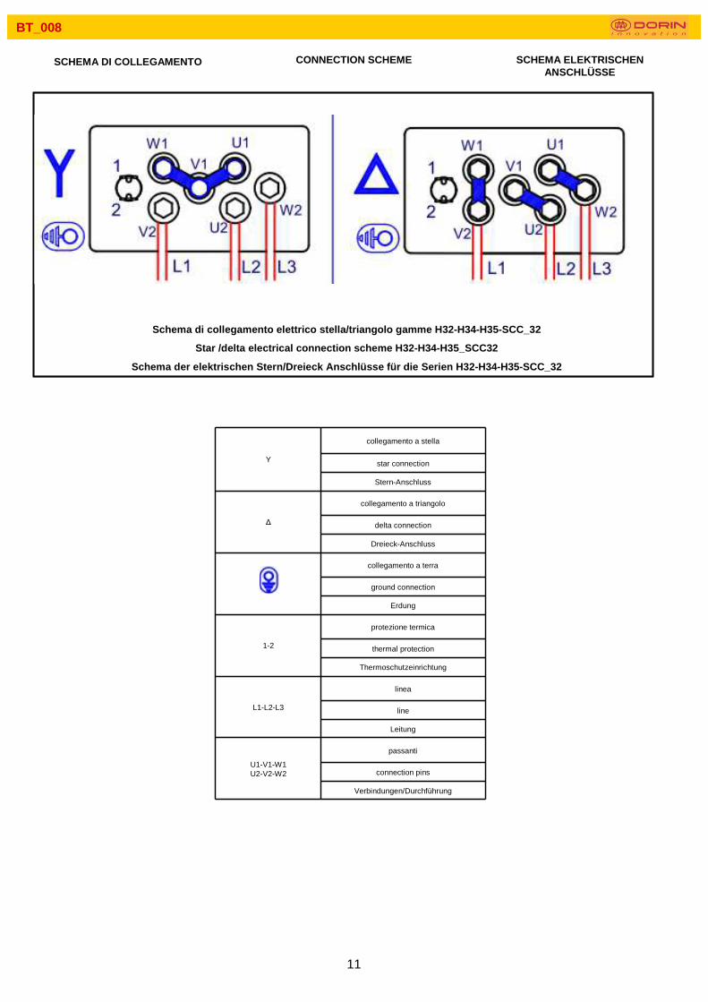
SCHEMA DI COLLEGAMENTO CONNECTION SCHEME SCHEMA ELEKTRISCHEN ANSCHLÜSSE
Y
collegamento a stella
star connection
Stern-Anschluss
∆
collegamento a triangolo
delta connection
Dreieck-Anschluss
collegamento a terra
ground connection
Erdung
1-2
protezione termica
thermal protection
Thermoschutzeinrichtung
L1-L2-L3
linea
line
Leitung
U1-V1-W1U2-V2-W2
passanti
connection pins
Verbindungen/Durchführung
Schema di collegamento elettrico stella/triangolo gamme H32-H3 4-H35-SCC_32
Star /delta electrical connection scheme H32-H34-H35_SCC32
Schema der elektrischen Stern/Dreieck Anschlüsse für die Seri en H32-H34-H35-SCC_32
12
BT_008
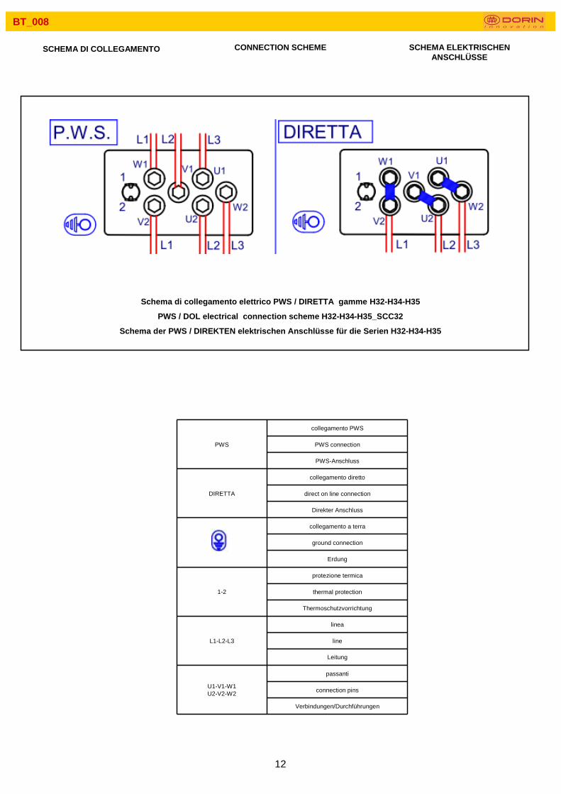
SCHEMA DI COLLEGAMENTO CONNECTION SCHEME SCHEMA ELEKTRISCHEN ANSCHLÜSSE
PWS
collegamento PWS
PWS connection
PWS-Anschluss
DIRETTA
collegamento diretto
direct on line connection
Direkter Anschluss
collegamento a terra
ground connection
Erdung
1-2
protezione termica
thermal protection
Thermoschutzvorrichtung
L1-L2-L3
linea
line
Leitung
U1-V1-W1U2-V2-W2
passanti
connection pins
Verbindungen/Durchführungen
Schema di collegamento elettrico PWS / DIRETTA gamme H32-H34-H 35
PWS / DOL electrical connection scheme H32-H34-H35_SCC32
Schema der PWS / DIREKTEN elektrischen Anschlüsse für die Serien H32-H34-H35

13
BT_008
COMPRESSORI SERIE H4-H41-H5-H6-H7 E GAMME SCC_4 CD
I compressori della serie H4-H5-H6-H7 e CD sono disponibili esclusivamente con motore trifase PWS.La seguente tabella mostra i motori disponibili per queste gamme di compressori.
H4-H5-H6-H7 AND SCC_4 AND CD COMPRESSOR RANGE
H4-H5-H6-H7 e CD range are equipped only with PWS three phases motor.Following table shows available motor type for these compressor ranges
VERDICHTER DER SERIEN H4-H41-H5-H6-H7 UND SCC_4 CD
Die Verdichter der Serien H4-H5-H6-H7 stehen ausschließlich mit dreiphasigen Motoren mit Teilwicklungsanlauf zur Verfügung.Die folgende Tabelle zeigt die für diese Verdichter-Palette zur Verfügung stehenden Motoren.
H4-H5-H6-H7-CD
MOTORE ALIMENTAZIONE COLLEGAMENTO
MOTORE SUPPLY VOLTAGE CONNECTION
MOTOR SPEISUNG VERBINDUNG
STANDARD 380-420 50 Hz / 440-480 60 Hz PWS or DOL
50 Hz 220-240 V
PWS or DOL60 Hz
380-420 V
220-240 V
PWS
collegamento PWS
T'1-T2
protezione termica
PWS connection thermal protection
PWS-Anschluss Thermoschutzvorrichtung
DIRETTA
collegamento diretto
L1-L2-L3
linea
direct on line connection line
Direkter Anschluss Leitung
collegamento a terra
1-2-37-8-9
passanti
ground connection connection pins
Erdanschluß Verbindungen / Durchführungen
Schema di collegamento elettrico PWS / DIRETTA gamme H4-H5-H6- H7 e SCC_4-CD
PWS / DOL electrical connection scheme H4-H5-H6-H7 and SCC_4 -CD
Schema der PWS/ DIREKTEN elektrischen Anschlüsse der Serie n

14
BT_008
MODALITA’ DI COLLEGAMENTO
• Aprire il coperchio della scatola attacchi elettrici;• Realizzare i collegamenti come riportato sull’adesivo all’interno della scatola attacchi elettrici, oppure in accordo a quanto contenuto in questo Bollettino Tecnico;• Utilizzare pressacavi idonei al fine di garantire il grado di protezione originale della scatola stessa;• Collegare la rete elettrica alla morsettiera utilizzando idoneo cavo elettrico isolato;• Serrare perfettamente i collegamenti elettrici nella posizione scelta;• Richiudere il coperchio della scatola terminali.
AttenzioneNon avviare il compressore con la scatola attacchi elettrici aperta
Istruzioni per il collegamento dei ponticelliPer un corretto collegamento dei ponticelli seguire la seguente procedura:� serrare il dado 1 su ogni ponticello� posizionare una rondella 2 su ogni dado� posizionare i ponticelli 3 secondo quanto indicato nello schema attacchi elettrici del compressore� posizionare il capocorda 4 come indicato nello schema attacchi elettrici� posizionare una rondella 5 su ogni passante� serrare il dado 6 su ogni passante.
Durante l’operazione di serraggio del dado 6 mantenere fermo il dado 1 con una seconda chiave. Nota: non serrare il dado 6 senza l’ausilio della chiave per mantenere il dado 1 in posizione.
CONNECTION MODE
• Open the terminal box cover;• Arrange the connection tabs in accordance with the adhesive diagram inside the box or in accordance with this Technical Bulletin;• Use appropriate cable glands to ensure the integrity of the box to original standard;• Connect the wires to the terminals using appropriate insulated cable;• Ensure that the terminals are tightly fastened in the selected position;• Re-fit the terminal box cover.
WarningDo not start compressor with the electrical box open
Electrical bridges installationFor a correct installation of the electrical bridges on the pins follow the procedure:� tighten the nut 1 on every pin� put a washer 2 on every nut� put the bridges on the pins in accordance to the selected scheme� put the cable on the selected pins in accordance to the electrical scheme� put a washer 5 on every pin� tighten the nut 6 on every pin.
During tightening the net 6 hold the nut 1on position using an other wrench. Note: do not tighten the nut 6 without using the other wrench on the nut .
ANSCHLUSSART
• Den Deckel des Elektroschaltkastens öffnen;• Den Anleitungen folgen, die auf dem Etikett beschrieben sind, dass sich im Schaltkasten selber befindet oder folgen Sie den Angaben der vorliegenden technischen Anleitung;• Geeignete Kabelhalter verwenden, um die ursprüngliche Schutzleistung des Kastens selber zu gewährleisten;• Das Stromnetz an die Klemme mit einem geeigneten und isolierten Stromkabel anschließen;• Die elektrischen Verbindungen an der gewünschten Stelle perfekt anziehen;• Den Deckel des Anschlusskastens wieder schließen;Achtung!Den Verdichter nicht bei offenem Anschlusskasten starten
Anleitungen für den Anschluss der BrückenUm die Brücken richtig anzuschließen der nachstehenden Prozedur folgen:� Mutter 1 auf jeder Brücke anziehen� eine Unterlegscheibe 2 auf jede Mutter geben� Brücken 3 gemäß den Anleitungen des Schaltplans des Verdichters platzieren� Kabelschuh 4 wie im Schema der elektrischen Anschlüsse platzieren� eine Unterlegscheibe 5 auf jede Verbindung geben� Mutter 6 auf jeder Verbindung anziehen
Beim Anziehen von Mutter 6, Mutter 1 mit einem zweiten Schlüssel festhalten. Hinweis: Die Mutter 6 nicht ohne Schlüssel anziehen, um Mutter 1 in Stellung zu halten.

15
BT_008
BT_008-12A1LTZ
NOTE NOTE NOTE

OFFICINE MARIO DORIN S.p.A.Via Aretina, 388; 50061 Compiobbi Firenze (Italy)
Tel. +39.055.623211 - Fax +39.055.62321380
www.dorin.com - [email protected]