boiler regulator ecomax860p1-k standard ecomax860p1 … · boiler enters firing-up stage. there is...
TRANSCRIPT
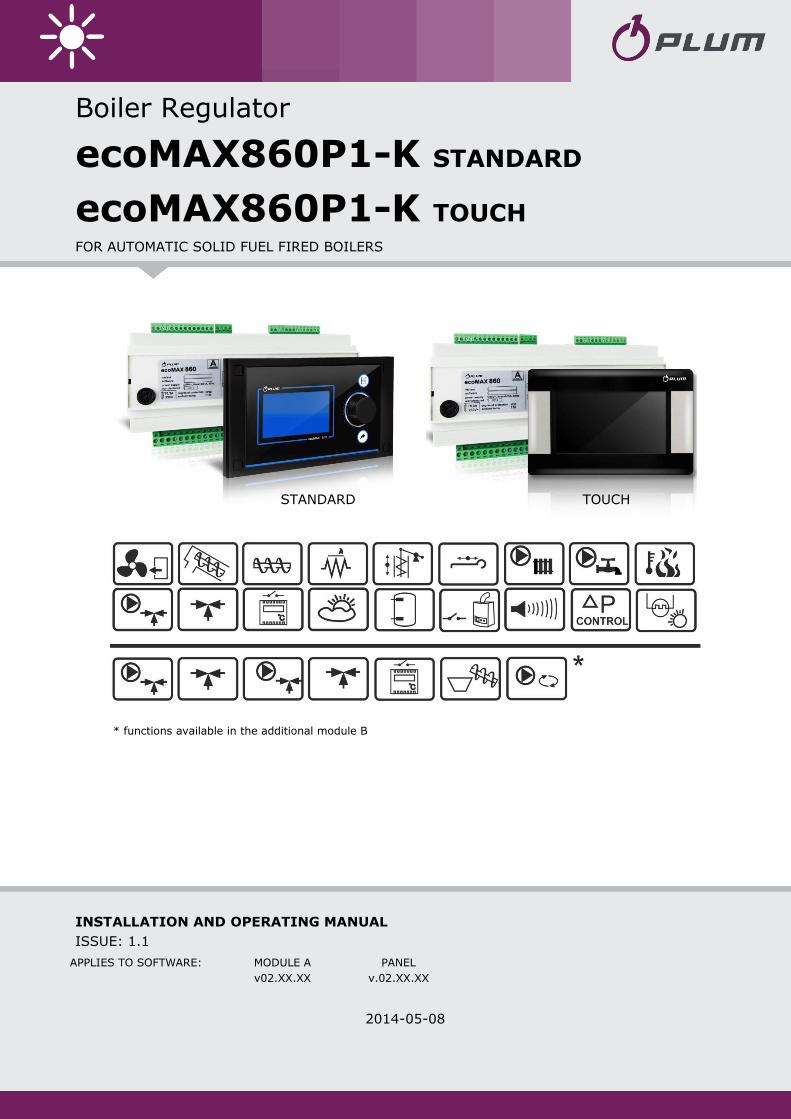
Boiler Regulator
ecoMAX860P1-K STANDARD
ecoMAX860P1-K TOUCH FOR AUTOMATIC SOLID FUEL FIRED BOILERS
* functions available in the additional module B
INSTALLATION AND OPERATING MANUAL
ISSUE: 1.1
2014-05-08
APPLIES TO SOFTWARE: MODULE A PANEL
v02.XX.XX v.02.XX.XX
STANDARD TOUCH

CONTENTS
1 RECOMMENDATIONS REGARDING SAFETY ........ 4
2 GENERAL ............................................................. 5
3 INFORMATION ABOUT DOCUMENTATION ......... 5
4 STORAGE OF DOCUMENTATION ......................... 5
5 APPLIED SYMBOLS .............................................. 5
6 DIRECTIVE WEEE 2002/96/EG ACT ON
ELECTRICAL AND ELECTRONIC EQUIPMENT ................... 5
REGULATOR INSTRUCTION MANUAL ............ 7
7 STRUCTURE – MAIN MENU ................................. 8
8 OPERATING THE REGULATOR ............................. 9
8.1 DESCRIPTION OF DISPLAY MAIN WINDOW – TOUCH
VERSION ............................................................. 9
8.2 SWITCHING ON AND OFF THE BOILER ...................... 10
8.3 MAIN WINDOW IN THE STANDARD VERSION ............ 11
8.4 SETTING PRESET BOILER TEMPERATURE ................... 12
8.5 FIRING-UP ..................................................... 12
8.6 OPERATION ................................................... 12
8.7 SUPERVISION ................................................ 12
8.8 BURNING OFF ................................................ 13
8.9 STANDSTILL ................................................... 13
8.10 DOMESTIC HOW WATER SETTINGS DHW ................ 13
8.11 SETTING PRESET DHW TEMPERATURE ................... 13
8.12 DHW TANK HYSTERESIS ...................................... 13
8.13 ENABLING THE SUMMER FUNCTION .................... 13
8.14 MIXER CIRCUITS SETTINGS ................................... 14
8.15 WEATHER CONTROLLED OPERATION ...................... 15
8.16 DESCRIPTION OF NIGHT TIME DECREASE SETTINGS .... 16
8.17 CIRCULATING PUMP CONTROL .............................. 16
8.18 FUEL LEVEL SETUP .............................................. 17
8.19 OPERATION WITH ADDITIONAL FEEDER ................... 17
8.20 INFORMATION ................................................... 18
8.21 MANUAL CONTROL ............................................ 18
8.22 FAVOURITE MENU .............................................. 18
8.23 ROOM CONTROL PANEL ....................................... 18
REGULATOR INSTALLATION AND SERVICE
SETTINGS MANUAL .................................... 19
9 HYDRAULIC DIAGRAMS ..................................... 20
9.1 DIAGRAM 1 ...................................................... 20
9.2 DIAGRAM 2 ...................................................... 21
9.3 DIAGRAM 3 ...................................................... 22
10 TECHNICAL DATA .............................................. 23
11 CONDITIONS OF STORAGE AND TRANSPORT ... 23
12 REGULATOR INSTALLATION ............................... 23
12.1 ENVIRONMENTAL CONDITIONS .............................. 23
12.2 INSTALLATION REQUIREMENTS .............................. 23
12.3 ASSEMBLY OF CONTROL PANEL .............................. 23
12.4 ASSEMBLY OF TOUCH CONTROL PANEL.................. 24
12.5 DISASSEMBLY OF CONTROL PANEL .......................... 25
12.6 MOUNTING OF WORKING MODULE ........................ 25
12.7 IP PROTECTION RATE ........................................... 26
12.8 CONNECTING ELECTRICAL SYSTEM .......................... 27
12.9 WIRING DIAGRAM .............................................. 28
12.10 CONNECTION OF TEMPERATURE SENSORS ................ 30
12.11 CONNECTING WEATHER SENSOR ............................ 30
12.12 CHECKING TEMPERATURE SENSORS ........................ 30
12.13 CONNECTION OF MIXERS ROOM THERMOSTAT .......... 31
12.14 CONNECTION OF BOILER'S ROOM THERMOSTAT ........ 31
12.15 CONNECTION OF RESERVE BOILER .......................... 31
12.16 CONNECTION OF ALARM SIGNALLING ...................... 32
12.17 CONNECTION OF MIXER ....................................... 33
12.18 CONNECTING TEMPERATURE LIMITER STB ............... 33
12.19 CONNECTING ROOM PANEL .................................. 33
13 SERVICE MENU STRUCTURE .............................. 34
14 SOFTWARE UPGRADE ........................................ 36
15 DESCRIPTION OF ALARMS ................................. 37
16 OTHERS .............................................................. 37
16.1 POWER SUPPLY DECAY ......................................... 37
16.2 ANTI-FREEZING PROTECTION ................................. 37
16.3 FUNCTION OF PROTECTING PUMPS AGAINST
STAGNATION ..................................................... 37
16.4 REPLACEMENT OF MAINS FUSE .............................. 37
16.5 REPLACEMENT OF CONTROL PANEL ........................ 37
17 REVISION HISTORY ............................................ 38

4
1 RECOMMENDATIONS REGARDING
SAFETY
Requirements concerning safety are
described in detail in individual
chapters of this manual. Apart from
them, the following requirements
should in particular be observed.
Before starting assembly,
repairs or maintenance, as well
as during any connection
works, please make sure that
the mains power supply is
disconnected and that terminals
and electric wires are devoid of
voltage.
After the regulator is turned off
using the keyboard, dangerous
voltage still can occur on its
terminals.
The regulator cannot be used at
variance with its purpose.
Additional automatics which
protect the boiler, central
heating (CH) system, and
domestic hot water system
against results of malfunction of
the regulator, or of errors in its
software, should be applied.
Choose the value of the
programmed parameters
accordingly to the given type of
boiler and fuel, taking into
consideration all the operational
conditions of the system.
Incorrect selection of the
parameters can cause
malfunction of the boiler (e.g.
overheating of the boiler, the
flame going back to the fuel
feeder, etc.),
The regulator is intended for
boiler manufacturers. Before
applying the regulator, a boiler
manufacturer should check if
the regulator’s mating with the
given boiler type is proper, and
whether it can cause danger.
The regulator is not an
intrinsically safe device, which
means that in the case of
malfunction it can be the source
of a spark or high temperature,
which in the presence of
flammable dusts or liquids can
cause fire or explosion. Thus,
the regulator should be
separated from flammable
dusts and gases, e.g. by means
of an appropriate body.
The regulator must be installed
by a boiler manufacturer in
accordance with the applicable
safety standards.
The programmed parameters
should only be altered by a
person familiarized with this
manual.
The device should only be used
in heating systems in
accordance with the applicable
regulations.
The electric system in which the
regulator operates must be
protected by means of a fuse,
selected appropriately to the
applied loads.
The regulator cannot be used if
its casing is damaged.
In no circumstances can the
design of the regulator be
modified.
Electronic isolation of the
connected devices is applied in
this regulator.
Keep the regulator out of reach
of children.
5
2 General
The regulator is a modern electronic device
designed to control pellet-fired boiler
operation with optical flame brightness
sensor. The regulator is compatible with an
air pressure sensor allowing for a precise
combustion control.
It can be used to control the operation of an
unregulated central heating circuit, HUW
circuit and three regulated heating circuits.
Preset temperature of heating circuits may
be set on the basis of weather sensor read-
out. A possibility to work together with room
thermostats helps to maintain comfortable
temperature in heated rooms. Moreover, if
needed, the equipment switches on gas -or
oil fired reserve boiler.
The regulator may operate in connection with
additional control panel installed in rooms.
Regulator is easy to operate in an intuitive
manner. It may be used in households and
other similar premises and in light industry
facilities.
3 Information about documentation
The regulator manual is a supplement for the
boiler manual. In particular, except for this
manual, the boiler manual should also be
observed. The regulator manual is divided
into two parts: for user and fitter. Yet, both
parts contain important information,
significant for safety issues, hence the user
should read both parts of the manual.
We are not responsible for any damages
caused by failure to observe these
instructions.
4 Storage of documentation
This assembly and operation manual, as well
as any other applicable documentation,
should be stored diligently, so that it was
available at any time. In the case of removal
or sale of the device, the attached
documentation should be handed over to the
new user / owner.
5 Applied symbols
In this manual the following graphic symbols
are used:
- useful information and tips,
- important information, failure to
observe these can cause damage of
property, threat for human and
household animal health and life.
Caution: the symbols indicate important
information, in order to make the manual more
lucid. Yet, this does not exempt the user from the
obligation to comply with requirements which are
not marked with a graphic symbol.
6 Directive WEEE 2002/96/EG Act on
electrical and electronic equipment
Recycle the product and the
packaging at the end of the
operational use period in an
appropriate manner.
Do not dispose of the product
together with normal waste.
Do not burn the product.


REGULATOR INSTRUCTION MANUAL
ecoMAX860P1-K
8
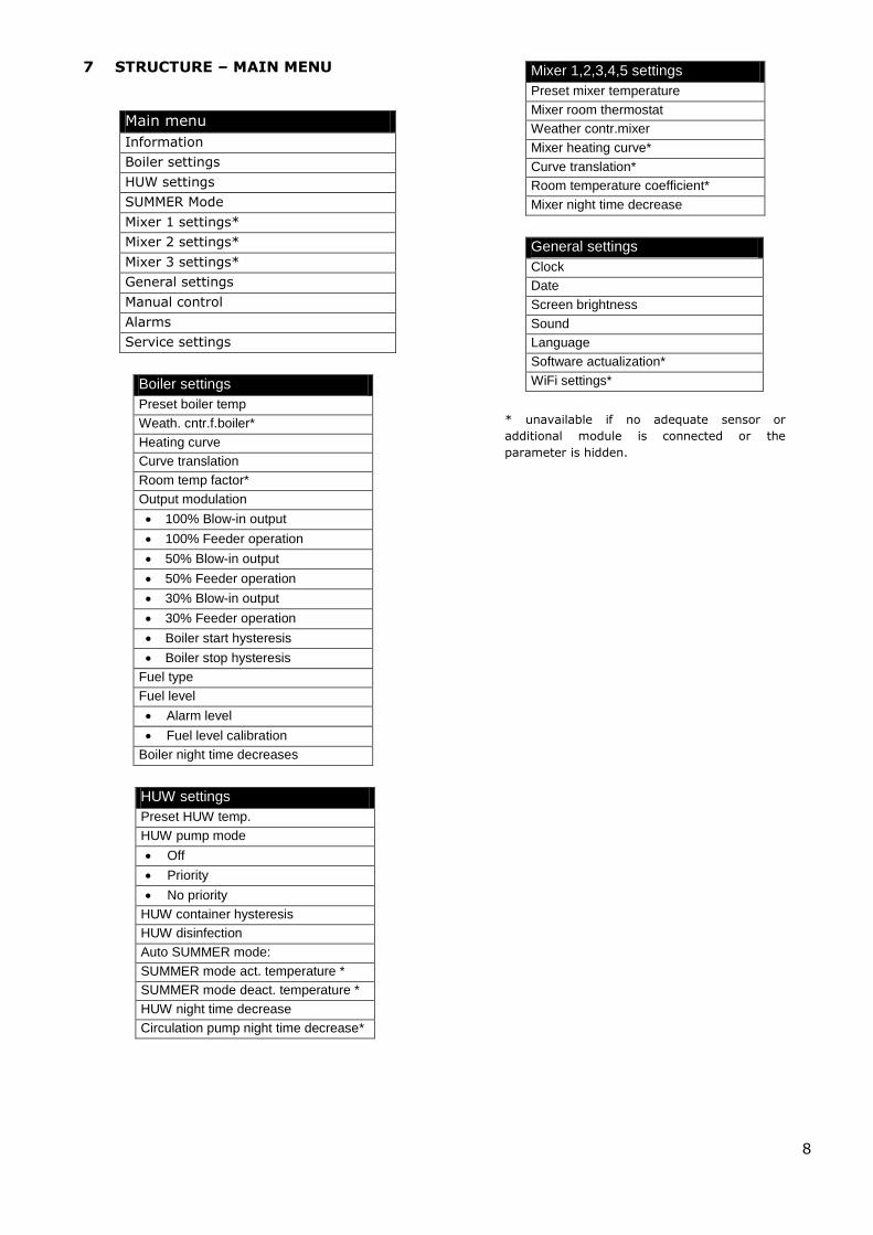
7 STRUCTURE – MAIN MENU
Boiler settings
Preset boiler temp
Weath. cntr.f.boiler*
Heating curve
Curve translation
Room temp factor*
Output modulation
100% Blow-in output
100% Feeder operation
50% Blow-in output
50% Feeder operation
30% Blow-in output
30% Feeder operation
Boiler start hysteresis
Boiler stop hysteresis
Fuel type
Fuel level
Alarm level
Fuel level calibration
Boiler night time decreases
HUW settings
Preset HUW temp.
HUW pump mode
Off
Priority
No priority
HUW container hysteresis
HUW disinfection
Auto SUMMER mode:
SUMMER mode act. temperature *
SUMMER mode deact. temperature *
HUW night time decrease
Circulation pump night time decrease*
Mixer 1,2,3,4,5 settings
Preset mixer temperature
Mixer room thermostat
Weather contr.mixer
Mixer heating curve*
Curve translation*
Room temperature coefficient*
Mixer night time decrease
General settings
Clock
Date
Screen brightness
Sound
Language
Software actualization*
WiFi settings*
* unavailable if no adequate sensor or
additional module is connected or the
parameter is hidden.
Main menu
Information
Boiler settings
HUW settings
SUMMER Mode
Mixer 1 settings*
Mixer 2 settings*
Mixer 3 settings*
General settings
Manual control
Alarms
Service settings

9
8 Operating the regulator
This section briefly describes how the regulator should be operated.
8.1 Description of display main window – touch version
Fig. 1 Display main window.
Legend:
1. Mode of regulator operation: FIRING-UP,
OPERATION, SUPERVISION, BURNING
OFF, STANDSTILL,
2. preset boiler temperature,
3. measured boiler temperature,
4. key to enter ’’Menu” list
5. Information fields:
fan,
feeder 1,
feeder 2,
pump,
lighter,
6. measured temperature of HUW container,
7. preset temperature of HUW container,
8. clock time and weekday
9. outside temperature (weather),
10. field of functions, which modify preset
boiler temperature -meaning of the symbols:
- opening of room thermostat contacts
– preset room temperature has been
reached;
- of preset boiler temperature for
active time intervals;
- increase of preset boiler temperature
for the time of HUW container filling;
- increase of preset boiler temperature
by mixer circuit;
- increase of preset temperature for
buffer loading.
Both, left and right windows may display
different information. By touching the screen,
you may navigate between displayed
information: mixer circuits information
window, HUW window, fuel level window.
To have the fuel level displayed, first enter
the settings acc. sec.8.18. Note: fuel level
may be displayed on ecoSTER-TOUCH room
control panel.
Boiler temperature HUW temperature
OPERATION THU
10
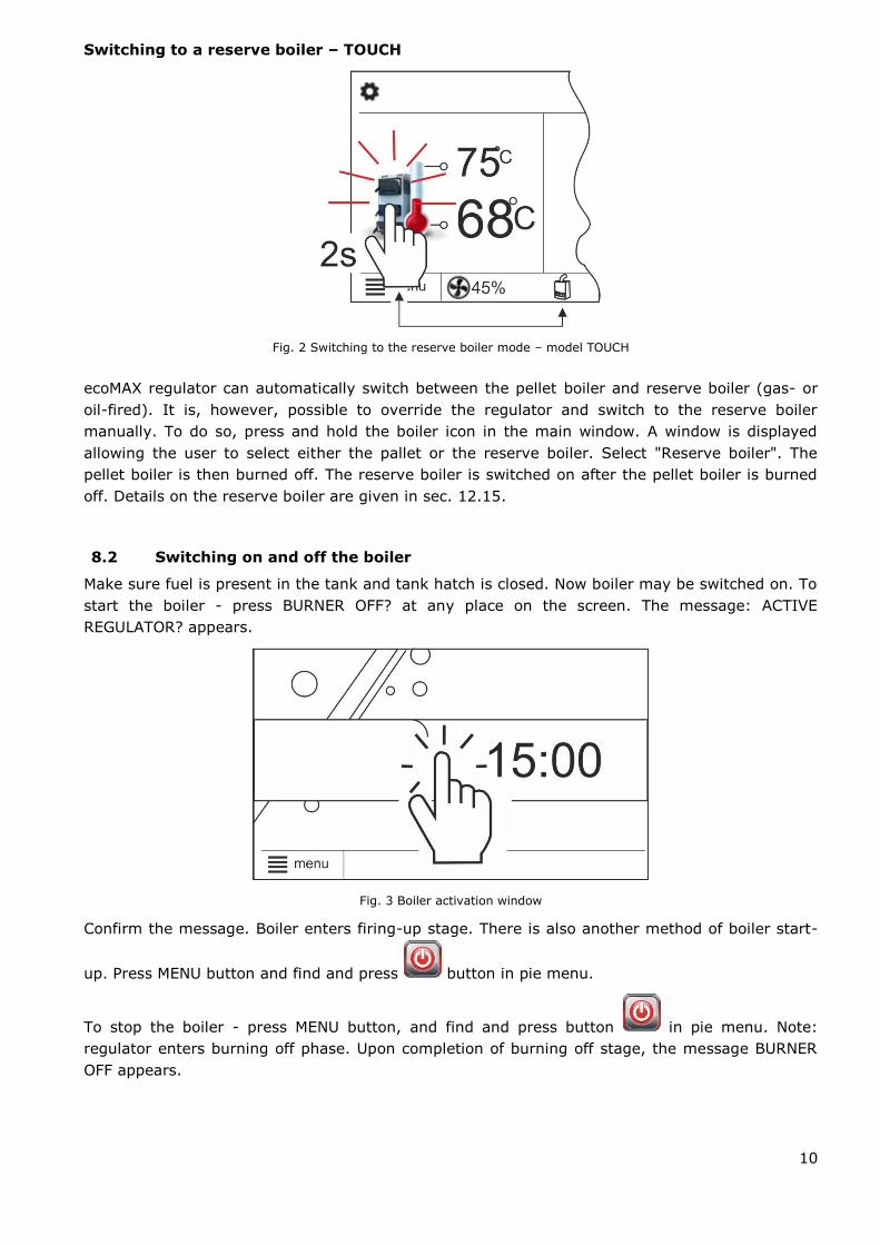
Switching to a reserve boiler – TOUCH
Fig. 2 Switching to the reserve boiler mode – model TOUCH
ecoMAX regulator can automatically switch between the pellet boiler and reserve boiler (gas- or
oil-fired). It is, however, possible to override the regulator and switch to the reserve boiler
manually. To do so, press and hold the boiler icon in the main window. A window is displayed
allowing the user to select either the pallet or the reserve boiler. Select "Reserve boiler". The
pellet boiler is then burned off. The reserve boiler is switched on after the pellet boiler is burned
off. Details on the reserve boiler are given in sec. 12.15.
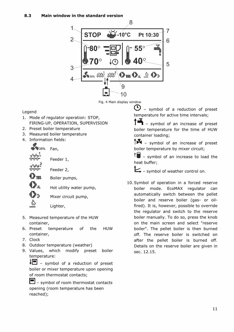
8.2 Switching on and off the boiler
Make sure fuel is present in the tank and tank hatch is closed. Now boiler may be switched on. To
start the boiler - press BURNER OFF? at any place on the screen. The message: ACTIVE
REGULATOR? appears.
Fig. 3 Boiler activation window
Confirm the message. Boiler enters firing-up stage. There is also another method of boiler start-
up. Press MENU button and find and press button in pie menu.
To stop the boiler - press MENU button, and find and press button in pie menu. Note:
regulator enters burning off phase. Upon completion of burning off stage, the message BURNER
OFF appears.
11
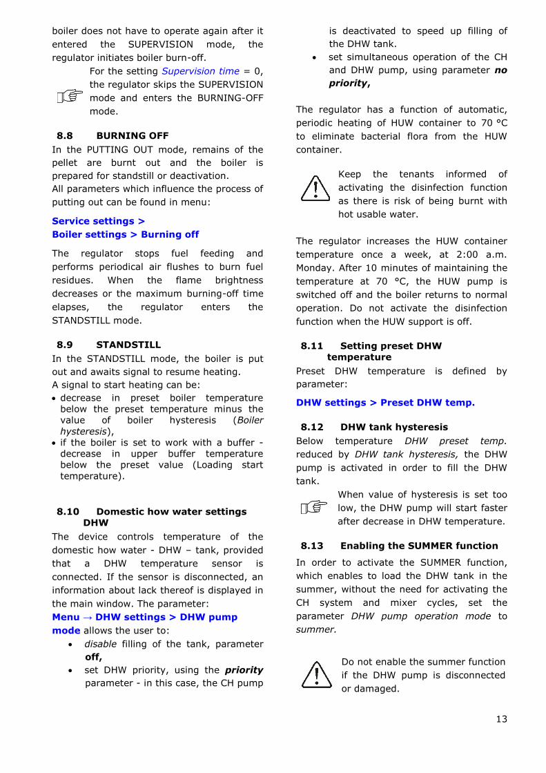
8.3 Main window in the standard version
Fig. 4 Main display window
Legend
1. Mode of regulator operation: STOP,
FIRING-UP, OPERATION, SUPERVISION
2. Preset boiler temperature
3. Measured boiler temperature
4. Information fields:
Fan,
Feeder 1,
Feeder 2,
Boiler pumps,
Hot utility water pump,
Mixer circuit pump,
Lighter,
5. Measured temperature of the HUW
container,
6. Preset temperature of the HUW
container,
7. Clock
8. Outdoor temperature (weather)
9. Values, which modify preset boiler
temperature:
– symbol of a reduction of preset
boiler or mixer temperature upon opening
of room thermostat contacts;
– symbol of room thermostat contacts
opening (room temperature has been
reached);
– symbol of a reduction of preset
temperature for active time intervals;
– symbol of an increase of preset
boiler temperature for the time of HUW
container loading;
– symbol of an increase of preset
boiler temperature by mixer circuit;
– symbol of an increase to load the
heat buffer;
– symbol of weather control on.
10. Symbol of operation in a forced reserve
boiler mode. EcoMAX regulator can
automatically switch between the pellet
boiler and reserve boiler (gas- or oil-
fired). It is, however, possible to override
the regulator and switch to the reserve
boiler manually. To do so, press the knob
on the main screen and select "reserve
boiler". The pellet boiler is then burned
off. The reserve boiler is switched on
after the pellet boiler is burned off.
Details on the reserve boiler are given in
sec. 12.15.

12
8.4 Setting preset boiler
temperature
Preset boiler temperature, just like the
preset mixer circuit temperature, can be set
in the menu (possible settings of these
temperatures are limited by the scope of
their corresponding regulator service
parameters).
Menu→ Boiler settings > Preset boiler
temp.
Menu→ Mixer 1,2,3,4 settings > Preset
mixer temp.
The value set as Preset boiler temp. is
ignored by the regulator if the preset boiler
temperature is controlled by weather sensor.
Regardless of that, the preset boiler
temperature is automatically increased in
order to fill the hot utility water tank and
feed heating mixer cycles.
8.5 FIRING-UP
The FIRING-UP mode is used for automatic
firing-up of furnace in the boiler. Total
duration of the firing-up process depends on
regulator settings (feeder operation time,
heater operation time, etc.) and on the
boiler’s status before firing-up. All
parameters which influence the firing-up
process can be found in menu:
Menu → Service settings >
Boiler settings > Firing-up
If firing up the furnace fails, further attempts
are carried out during which the fuel dose
(feeding time) is reduced to 10% of the dose
in the first attempt.
Consecutive attempts are visualised by
numbers next to the lighter symbol .
After three unsuccessful attempts, an alarm
Failed firing-up attempt is reported. In such
case, the boiler operation is halted. Boiler
operation cannot be continued automatically
- service crew must intervene. After
removing causes of impossibility to fire-up,
the boiler must be restarted.
8.6 OPERATION
The fan operates continuously. Fuel feeder is
activated cyclically. A cycle consists of feeder
operation time and duration of feeding
interval
Parameters related with the Operation mode
are: Feeder operation time and Fan output
in:
Menu → Boiler settings → Output
modulation.
8.7 SUPERVISION
The regulator automatically enters the
SUPERVISION mode without any user's
intervention once actual temperature has
exceeded the boiler preset temperature by
5°C.
In the SUPERVISION mode, the regulator
supervises the fire in the furnace so that it
does not burn off. To achieve that, the
burner power is kept low which together with
correctly adjusted parameters prevents any
increase of the temperature. Burner power in
the SUPERVISION mode and other
SUPERVISION parameters can be found in:
Menu → Service Settings → Burner
Settings → Supervision
SUPERVISION parameters should be set in
accordance with the recommendations of the
boiler or burner manufacturer. They should
be such values so that the fire in the furnace
does not burn off during boiler standstills
(and it should not burn too intensely as the
boiler temperature may increase). Feeder
operation and standstill times in the
SUPERVISION mode are set with the
following parameters: Feeding Time
SUPERVISION, Cycle time SUPERVISION and
Blow-in SUPERVISION mode.
Parameters should be so selected
that the boiler temperature in this
mode gradually drops. Incorrect
settings may lead to boiler
overheating.
The maximum boiler operation time in the
SUPERVISION mode is defined by
Supervision time. If, after this time, the
13
boiler does not have to operate again after it
entered the SUPERVISION mode, the
regulator initiates boiler burn-off.
For the setting Supervision time = 0,
the regulator skips the SUPERVISION
mode and enters the BURNING-OFF
mode.
8.8 BURNING OFF
In the PUTTING OUT mode, remains of the
pellet are burnt out and the boiler is
prepared for standstill or deactivation.
All parameters which influence the process of
putting out can be found in menu:
Service settings >
Boiler settings > Burning off
The regulator stops fuel feeding and
performs periodical air flushes to burn fuel
residues. When the flame brightness
decreases or the maximum burning-off time
elapses, the regulator enters the
STANDSTILL mode.
8.9 STANDSTILL
In the STANDSTILL mode, the boiler is put
out and awaits signal to resume heating.
A signal to start heating can be:
decrease in preset boiler temperature
below the preset temperature minus the
value of boiler hysteresis (Boiler
hysteresis),
if the boiler is set to work with a buffer -
decrease in upper buffer temperature
below the preset value (Loading start
temperature).
8.10 Domestic how water settings
DHW
The device controls temperature of the
domestic how water - DHW – tank, provided
that a DHW temperature sensor is
connected. If the sensor is disconnected, an
information about lack thereof is displayed in
the main window. The parameter:
Menu → DHW settings > DHW pump
mode allows the user to:
disable filling of the tank, parameter
off,
set DHW priority, using the priority
parameter - in this case, the CH pump
is deactivated to speed up filling of
the DHW tank.
set simultaneous operation of the CH
and DHW pump, using parameter no
priority,
The regulator has a function of automatic,
periodic heating of HUW container to 70 °C
to eliminate bacterial flora from the HUW
container.
Keep the tenants informed of
activating the disinfection function
as there is risk of being burnt with
hot usable water.
The regulator increases the HUW container
temperature once a week, at 2:00 a.m.
Monday. After 10 minutes of maintaining the
temperature at 70 °C, the HUW pump is
switched off and the boiler returns to normal
operation. Do not activate the disinfection
function when the HUW support is off.
8.11 Setting preset DHW
temperature
Preset DHW temperature is defined by
parameter:
DHW settings > Preset DHW temp.
8.12 DHW tank hysteresis
Below temperature DHW preset temp.
reduced by DHW tank hysteresis, the DHW
pump is activated in order to fill the DHW
tank.
When value of hysteresis is set too
low, the DHW pump will start faster
after decrease in DHW temperature.
8.13 Enabling the SUMMER function
In order to activate the SUMMER function,
which enables to load the DHW tank in the
summer, without the need for activating the
CH system and mixer cycles, set the
parameter DHW pump operation mode to
summer.
Do not enable the summer function
if the DHW pump is disconnected
or damaged.
14
The SUMMER function can be enabled
automatically, on the basis of readouts from
the weather sensor. This functionality is
enabled with the following parameters:
DHW settings > Auto SUMMER detect.
DHW settings > Activ.temp.SUMMER
DHW settings > Deactiv.temp.SUMMER
8.14 Mixer circuits settings
Settings for the first mixer circuit can be
found in the menu:
Menu → Mixer 1 settings
Settings for other mixers can be accessed in
next menu items and they are identical for
each circuit.
Settings for mixer (without weather
sensor)
It is necessary to manually set the required
water temperature in the heating mixer
circuit using parameter Preset mixer temp.,
e.g. at a value of 50°C. The value should
allow to obtain the required room
temperature.
After connecting room thermostat, it is
necessary to set a value of decrease in
preset mixer temperature by thermostat
(parameters Mixer room therm.) e.g. at 5°C.
This value should be selected by trial and
error. The room thermostat can be a
traditional thermostat (no/nc), or room panel
ecoSTER-TOUCH. Upon activation of the
thermostat, the preset mixer circuit
temperature will be decreased, which, if
proper decrease value is selected, will stop
growth of temperature in the heated room.
Settings for mixer with weather sensor
(without room thermostat ecoSTER-TOUCH)
Set parameter Weather contr.mixer to on.
Select weather curve as per point 8.15
Using parameter Curve translation, set
preset room temperature following the
formula:
Preset room temperature = 20°C + heating
curve translation.
Example.
In this setup, it is possible to connect a room
thermostat which will equalize the inaccuracy
of selecting heating curve, if the selected
heating curve value is too high. In such case,
it is necessary to set the value of preset
mixer temperature decrease by thermostat,
e.g. at 2°C. After opening of the thermostat
contacts, the preset mixer circuit
temperature will be decreased, which, if
proper decrease value is selected, will stop
growth of temperature in the heated room.
Settings for mixer with weather sensor
and with room thermostat ecoSTER-
TOUCH
Set parameter Weather contr.mixer to on.
Select weather curve as per point. 8.15
The ecoSTER-TOUCH regulator automatically
translates the heating curve, depending on
the preset room temperature. The regulator
relates the setting to 20 °C, e.g. for preset
room temperature = 22 °C, the regulator will
translate the heating curve by 2°C, for
preset room temperature = 18 °C, the
regulator will translate the heating curve by
-2 °C. In some cases described in point. 8.15
it may be necessary to fine-tune the heating
curve translation.
In this setup, the ecoSTER-TOUCH room
thermostat can:
- decrease the heating cycle temperature by
a constant value when the preset room
temperature is reached. Analogously, as
specified in the previous point (not
recommended), or
- automatically, continuously correct the
heating cycle temperature.
It is not recommended to use both
options at the same time.
Automatic correction of room temperature is
carried out in accordance with the following
formula:
Correction = (Preset room temperature -
measured room temperature) x room
temperature coefficient /10

15
Example.
Preset temperature in the heated room (set
at ecoSTER200) = 22 °C. Temperature
measured in the room (by ecoSTER200) =
20 °C. Room temp. coeff. = 15.
Preset mixer temperature will be increased
by (22 °C - 20 °C) x 15/10 = 3 °C.
It is necessary to find appropriate value of
the Room temp. coeff. Range: 0…50. The
higher the coefficient, the greater the
correction of preset boiler temperature. If
the setting is “0”, the preset mixer
temperature is not corrected. Note: setting a
value of the room temperature coefficient too
high may cause cyclical fluctuations of the
room temperature!
8.15 Weather controlled operation
Depending on the temperature measured
outside the building, both preset boiler
temperature and temperatures of mixer
circuits can be controlled automatically. If
proper heating curve is selected, the
temperature of the circuits is calculated
automatically, depending on the outdoor
temperature. Thus, if the selected heating
curve is appropriate for the given building,
the room temperature stays more or less the
same, regardless of the temperature outside.
Note: during trial and error selection of
appropriate heating curve, it is necessary to
exclude influence of the room thermostat on
regulator operation (regardless of whether
the room thermostat is connected or not), by
setting the parameter:
Mixer 1 settings > Mixer room therm. to
“0”.
If a room panel ecoSTER200 is connected, it
is also necessary to set the parameter Room
temp. coeff. to “0”.
Guidelines for proper setting
of the heating curve:
- floor heating 0,2 -0,6
- radiator heating 1,0 - 1,6
- boiler 1,8 - 4
Drawing 1 Heating curves.
Guidelines for selection of appropriate
heating curve:
- if the outdoor temperature drops, and the
room temperature increases, the selected
heating curve value is too high,
- if the outdoor temperature drops, and the
room temperature drops as well, the selected
heating curve value is too low,
- if during frosty weather the room
temperature is proper, but when it gets
warmer - it is too low, it is recommended to
increase the Curve translation and to select a
lower heating curve,
- if during frosty weather the room
temperature is too low, and when it gets
warmer - it is too high, it is recommended to
decrease the Curve translation and to select
a higher heating curve.
Buildings with poor thermal insulation require
higher heating curves, whereas for buildings
which have good thermal insulation, the
heating curve can have lower value.
The regulator can increase or decrease the
preset temperature, calculated in accordance
with the heating curve, if it exceeds the
temperature range for the given circuit.
16
8.16 Description of night time
decrease settings
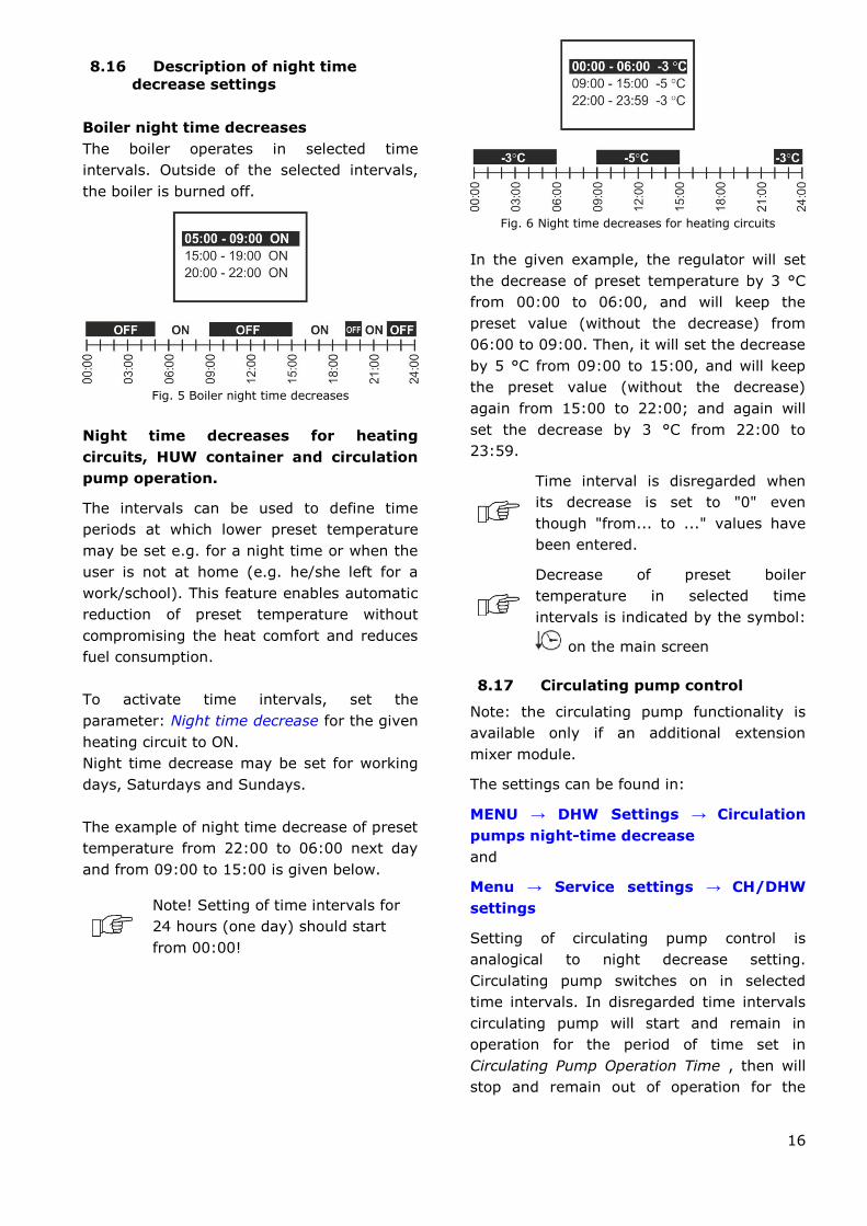
Boiler night time decreases
The boiler operates in selected time
intervals. Outside of the selected intervals,
the boiler is burned off.
Fig. 5 Boiler night time decreases
Night time decreases for heating
circuits, HUW container and circulation
pump operation.
The intervals can be used to define time
periods at which lower preset temperature
may be set e.g. for a night time or when the
user is not at home (e.g. he/she left for a
work/school). This feature enables automatic
reduction of preset temperature without
compromising the heat comfort and reduces
fuel consumption.
To activate time intervals, set the
parameter: Night time decrease for the given
heating circuit to ON.
Night time decrease may be set for working
days, Saturdays and Sundays.
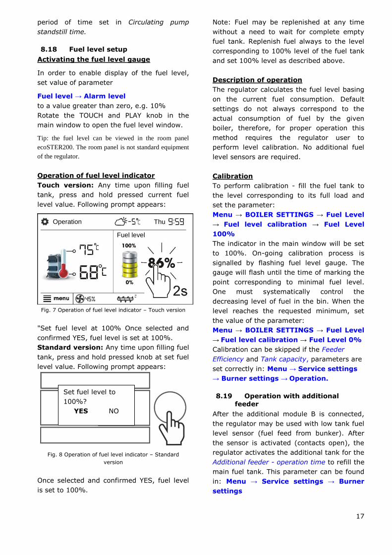
The example of night time decrease of preset
temperature from 22:00 to 06:00 next day
and from 09:00 to 15:00 is given below.
Note! Setting of time intervals for
24 hours (one day) should start
from 00:00!
Fig. 6 Night time decreases for heating circuits
In the given example, the regulator will set
the decrease of preset temperature by 3 °C
from 00:00 to 06:00, and will keep the
preset value (without the decrease) from
06:00 to 09:00. Then, it will set the decrease
by 5 °C from 09:00 to 15:00, and will keep
the preset value (without the decrease)
again from 15:00 to 22:00; and again will
set the decrease by 3 °C from 22:00 to
23:59.
Time interval is disregarded when
its decrease is set to "0" even
though "from... to ..." values have
been entered.
Decrease of preset boiler
temperature in selected time
intervals is indicated by the symbol:
on the main screen
8.17 Circulating pump control
Note: the circulating pump functionality is
available only if an additional extension
mixer module.
The settings can be found in:
MENU → DHW Settings → Circulation
pumps night-time decrease
and
Menu → Service settings → CH/DHW
settings
Setting of circulating pump control is
analogical to night decrease setting.
Circulating pump switches on in selected
time intervals. In disregarded time intervals
circulating pump will start and remain in
operation for the period of time set in
Circulating Pump Operation Time , then will
stop and remain out of operation for the
17
period of time set in Circulating pump
standstill time.
8.18 Fuel level setup
Activating the fuel level gauge
In order to enable display of the fuel level,
set value of parameter
Fuel level → Alarm level
to a value greater than zero, e.g. 10%
Rotate the TOUCH and PLAY knob in the
main window to open the fuel level window.
Tip: the fuel level can be viewed in the room panel
ecoSTER200. The room panel is not standard equipment
of the regulator.
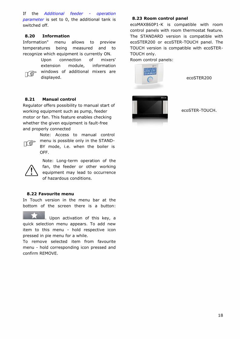
Operation of fuel level indicator
Touch version: Any time upon filling fuel
tank, press and hold pressed current fuel
level value. Following prompt appears:
Fig. 7 Operation of fuel level indicator – Touch version
"Set fuel level at 100% Once selected and
confirmed YES, fuel level is set at 100%.
Standard version: Any time upon filling fuel
tank, press and hold pressed knob at set fuel
level value. Following prompt appears:
Fig. 8 Operation of fuel level indicator – Standard
version
Once selected and confirmed YES, fuel level
is set to 100%.
Note: Fuel may be replenished at any time
without a need to wait for complete empty
fuel tank. Replenish fuel always to the level
corresponding to 100% level of the fuel tank
and set 100% level as described above.
Description of operation
The regulator calculates the fuel level basing
on the current fuel consumption. Default
settings do not always correspond to the
actual consumption of fuel by the given
boiler, therefore, for proper operation this
method requires the regulator user to
perform level calibration. No additional fuel
level sensors are required.
Calibration
To perform calibration - fill the fuel tank to
the level corresponding to its full load and
set the parameter:
Menu → BOILER SETTINGS → Fuel Level
→ Fuel level calibration → Fuel Level
100%
The indicator in the main window will be set
to 100%. On-going calibration process is
signalled by flashing fuel level gauge. The
gauge will flash until the time of marking the
point corresponding to minimal fuel level.
One must systematically control the
decreasing level of fuel in the bin. When the
level reaches the requested minimum, set
the value of the parameter:
Menu → BOILER SETTINGS → Fuel Level
→ Fuel level calibration → Fuel Level 0%
Calibration can be skipped if the Feeder
Efficiency and Tank capacity, parameters are
set correctly in: Menu → Service settings
→ Burner settings → Operation.
8.19 Operation with additional
feeder
After the additional module B is connected,
the regulator may be used with low tank fuel
level sensor (fuel feed from bunker). After
the sensor is activated (contacts open), the
regulator activates the additional tank for the
Additional feeder - operation time to refill the
main fuel tank. This parameter can be found
in: Menu → Service settings → Burner
settings
Set fuel level to
100%?
YES NO
Operation
Fuel level
Thu
18
If the Additional feeder - operation
parameter is set to 0, the additional tank is
switched off.
8.20 Information
Information" menu allows to preview
temperatures being measured and to
recognize which equipment is currently ON.
Upon connection of mixers'
extension module, information
windows of additional mixers are
displayed.
8.21 Manual control
Regulator offers possibility to manual start of
working equipment such as pump, feeder
motor or fan. This feature enables checking
whether the given equipment is fault-free
and properly connected
Note: Access to manual control
menu is possible only in the STAND-
BY mode, i.e. when the boiler is
OFF.
Note: Long-term operation of the
fan, the feeder or other working
equipment may lead to occurrence
of hazardous conditions.
8.22 Favourite menu
In Touch version in the menu bar at the
bottom of the screen there is a button:
. Upon activation of this key, a
quick selection menu appears. To add new
item to this menu - hold respective icon
pressed in pie menu for a while.
To remove selected item from favourite
menu - hold corresponding icon pressed and
confirm REMOVE.
8.23 Room control panel
ecoMAX860P1-K is compatible with room
control panels with room thermostat feature.
The STANDARD version is compatible with
ecoSTER200 or ecoSTER-TOUCH panel. The
TOUCH version is compatible with ecoSTER-
TOUCH only.
Room control panels:
ecoSTER200
ecoSTER-TOUCH.

REGULATOR INSTALLATION AND SERVICE SETTINGS MANUAL
ecoMAX860P1-K
20
9 Hydraulic diagrams
9.1 Diagram 1
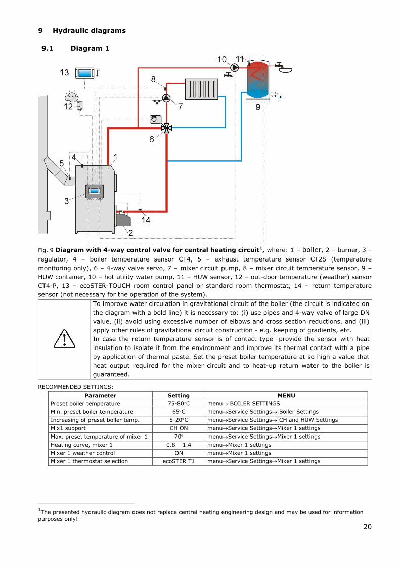
Fig. 9 Diagram with 4-way control valve for central heating circuit1, where: 1 – boiler, 2 – burner, 3 –
regulator, 4 – boiler temperature sensor CT4, 5 – exhaust temperature sensor CT2S (temperature
monitoring only), 6 – 4-way valve servo, 7 – mixer circuit pump, 8 – mixer circuit temperature sensor, 9 –
HUW container, 10 – hot utility water pump, 11 – HUW sensor, 12 – out-door temperature (weather) sensor
CT4-P, 13 – ecoSTER-TOUCH room control panel or standard room thermostat, 14 – return temperature
sensor (not necessary for the operation of the system).
To improve water circulation in gravitational circuit of the boiler (the circuit is indicated on
the diagram with a bold line) it is necessary to: (i) use pipes and 4-way valve of large DN
value, (ii) avoid using excessive number of elbows and cross section reductions, and (iii)
apply other rules of gravitational circuit construction - e.g. keeping of gradients, etc.
In case the return temperature sensor is of contact type -provide the sensor with heat
insulation to isolate it from the environment and improve its thermal contact with a pipe
by application of thermal paste. Set the preset boiler temperature at so high a value that
heat output required for the mixer circuit and to heat-up return water to the boiler is
guaranteed.
RECOMMENDED SETTINGS:
Parameter Setting MENU
Preset boiler temperature 75-80C menu BOILER SETTINGS
Min. preset boiler temperature 65C menuService Settings Boiler Settings
Increasing of preset boiler temp. 5-20C menuService Settings CH and HUW Settings
Mix1 support CH ON menuService SettingsMixer 1 settings
Max. preset temperature of mixer 1 70 menuService SettingsMixer 1 settings
Heating curve, mixer 1 0.8 – 1.4 menuMixer 1 settings
Mixer 1 weather control ON menuMixer 1 settings
Mixer 1 thermostat selection ecoSTER T1 menuService SettingsMixer 1 settings
1The presented hydraulic diagram does not replace central heating engineering design and may be used for information
purposes only!

21
9.2 Diagram 2
Fig. 10 Diagram with heat buffer2, where:1 – boiler, 2 – burner, 3 – regulator, 4 – boiler temperature
sensor, 5 – exhaust temperature sensor (temperature monitoring only), 6 – boiler pump, 7 – heat buffer, 8
– HUW pump, 9 – HUW container, 10 – HUW temperature sensor, 11 – mixing valve servo, 12 – mixer
circuit temperature sensor, 13 – mixer pump, 14 – ecoSTER200 room control panel with room thermostat
feature, 15 – 3-way thermostatic valve to protect return, 16 – upper sensor of buffer temperature, 17 –
lower sensor of buffer temperature, 18 – out-door temperature (weather) sensor.
RECOMMENDED SETTINGS:
Parameter Setting MENU
Preset boiler temperature 80C menuBoiler Settings
Min. preset boiler temperature 75C menuService Settings Boiler Settings
CH Pump Activation Temperature 55C menuService Settings CH and HUW Settings
Activate operation (buffer support) ON menuService Settings Buffer Settings
Buffer loading start temp. 50 menuService Settings Buffer Settings
Buffer loading end temp. 75 menuService Settings Buffer Settings
Mix1 support CH ON menuService SettingsMixer 1 settings
Max. preset temperature of mixer 1 70 menuService SettingsMixer 1 settings
Heating curve, mixer 1 0.8 – 1.4 menuMixer 1 settings
Mixer 1 weather control ON menuMixer 1 settings
Mixer 1 thermostat selection ecoSTER T1 menuService SettingsMixer 1 settings
2 The presented hydraulic diagram does not replace central heating engineering design and may be used for
information purposes only!
22
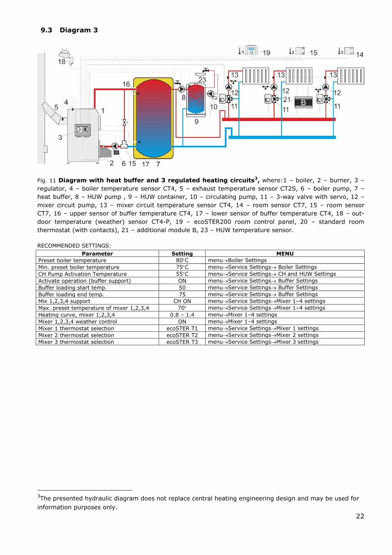
9.3 Diagram 3
Fig. 11 Diagram with heat buffer and 3 regulated heating circuits3, where:1 – boiler, 2 – burner, 3 –
regulator, 4 – boiler temperature sensor CT4, 5 – exhaust temperature sensor CT2S, 6 – boiler pump, 7 –
heat buffer, 8 – HUW pump , 9 – HUW container, 10 – circulating pump, 11 – 3-way valve with servo, 12 –
mixer circuit pump, 13 – mixer circuit temperature sensor CT4, 14 – room sensor CT7, 15 – room sensor
CT7, 16 – upper sensor of buffer temperature CT4, 17 – lower sensor of buffer temperature CT4, 18 – out-
door temperature (weather) sensor CT4-P, 19 – ecoSTER200 room control panel, 20 – standard room
thermostat (with contacts), 21 – additional module B, 23 – HUW temperature sensor.
RECOMMENDED SETTINGS:
Parameter Setting MENU
Preset boiler temperature 80C menuBoiler Settings
Min. preset boiler temperature 75C menuService Settings Boiler Settings
CH Pump Activation Temperature 55C menuService Settings CH and HUW Settings
Activate operation (buffer support) ON menuService Settings Buffer Settings
Buffer loading start temp. 50 menuService Settings Buffer Settings
Buffer loading end temp. 75 menuService Settings Buffer Settings
Mix 1,2,3,4 support CH ON menuService SettingsMixer 1–4 settings
Max. preset temperature of mixer 1,2,3,4 70 menuService SettingsMixer 1–4 settings
Heating curve, mixer 1,2,3,4 0.8 – 1.4 menuMixer 1–4 settings
Mixer 1,2,3,4 weather control ON menuMixer 1–4 settings
Mixer 1 thermostat selection ecoSTER T1 menuService SettingsMixer 1 settings
Mixer 2 thermostat selection ecoSTER T2 menuService SettingsMixer 2 settings
Mixer 3 thermostat selection ecoSTER T3 menuService SettingsMixer 3 settings
3The presented hydraulic diagram does not replace central heating engineering design and may be used for
information purposes only.
23
10 Technical data
Voltage 230V~; 50Hz;
Current consumed by regulator I = 0,04 A4
Maximum rated current 6 (6) A
Regulator protection rating IP20
Ambient temperature 0...50 C
Storage temperature 0...65 C
Relative humidity 5 - 85% without
steam condensation
Measuring range of
temperature sensors CT4 0...100 C
Measuring range of
temperature sensors CT4-P -35...40 C
Accuracy of temperature
measurements with sensors
CT4 and CT4-P
2 C
Terminals
network
screw terminals, wire
cross-section area
0.75 mm2 through
1.5mm2, screwing
torque 0.4Nm,
insulation removed:
6mm
communication
screw terminals, wire
cross-section area up
to 0.75mm2 ,
screwing torque 0.3
Nm, insulation
removed: 6 mm
Display (STANDARD) Graphic
display128x64
Display (TOUCH)
Color display
480x272 with touch
panel
External dimensions 210x115x60 mm
Total weight 1.4 kg
Standards PN-EN 60730-2-9
PN-EN 60730-1
Software class A
Protection class Suitable to build into
Class I devices
4 Power consumed by the regulator itself (with 2 working
modules and a control panel). Total power consumption
depends on the devices connected to the regulator.
Pollution degree
2nd pollution degree
acc. to PN-EN 60730-
1
11 Conditions of storage and
transport
The regulator cannot be exposed to direct
effects of weather, i.e. rain and sunlight.
Storage and transport temperature cannot
exceed the range of -15…65 °C.
During transport, the device cannot be
exposed to vibrations greater than those
typical of normal road transport.
12 REGULATOR INSTALLATION
12.1 Environmental conditions
Due to the risk of fire is prohibited to use the
controller in explosive gas and dust
enviroment (eg coal). Regulator should be
separated using appropriate enclosure.
In addition, controller cannot be used in the
presence of water vapor condensation and be
exposed to water.
12.2 Installation requirements
The regulator should be installed by a
qualified and authorised fitter, in accordance
with the applicable norms and regulations.
The manufacturer bears no responsibility for
damages caused by failure to observe this
manual. The regulator is to be built-in. The
regulator cannot be used as a stand-alone
device. The temperature of the ambient and
the fitting surface cannot exceed the range
of 0 - 50˚C. The device consists of two
modules: control panel and working module.
Both elements are connected with electric
wire.
12.3 Assembly of control panel
Control panel is designed to be attached to a
mounting plate. Provide appropriate heat
insulation between hot boiler walls and
control panel and cable harness. Space
required to assemble control panel of the
regulator is shown in Fig. 12. When installing
follow the instructions given below.

24
STEP 1
A hole must be made in the mounting plate,
in accordance with the drawing below.
Fig. 12 Fitting the regulator in a mounting plate, where:
1 – control panel, 2 – sheet metal screw
2.9x13, 3 – hole plug.
STEP 2
Remove the lid (5), plug the cable (6) and
put the lid (5) back on, securing it with
screws (4). The cable should be lead out
through the round groove in the enclosure.
Fig. 13 Connecting lead to the panel, where: 4- B3x6
screw for thermoplastic materials, 5 – lid, 6 –
lead connecting the control panel with the
executive panel.
Maximum length of the lead (6) is
5m with gauge of 0,5mm2
STEP 3
Screw the panel to the mounting plate using
sheet metal screws, insert the hole plugs.
Fig. 14 Conditions of enclosing the panel, where 1 –
panel, 2 –ventilation holes for air circulation (note: the
holes cannot decrease the required IP protection rate;
ventilation holes are not required if the limiting
temperature of the panel surroundings is not exceeded;
the ventilation holes do not always guarantee that the
temperature of the panel surroundings will be lowered,
in such case use other methods).
12.4 Assembly of TOUCH control panel
Control panel is designed to be attached to a
mounting plate. Provide appropriate heat
insulation between hot boiler walls and
control panel and cable harness. Space
required to assemble the control panel of the
regulator is shown in the figure below. When
installing follow the instructions given below.
25
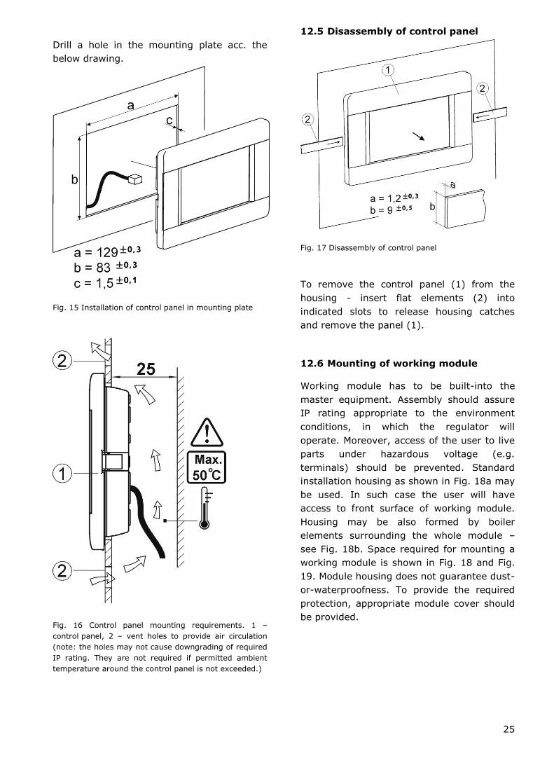
Drill a hole in the mounting plate acc. the
below drawing.
Fig. 15 Installation of control panel in mounting plate
Fig. 16 Control panel mounting requirements. 1 –
control panel, 2 – vent holes to provide air circulation
(note: the holes may not cause downgrading of required
IP rating. They are not required if permitted ambient
temperature around the control panel is not exceeded.)
12.5 Disassembly of control panel
Fig. 17 Disassembly of control panel
To remove the control panel (1) from the
housing - insert flat elements (2) into
indicated slots to release housing catches
and remove the panel (1).
12.6 Mounting of working module
Working module has to be built-into the
master equipment. Assembly should assure
IP rating appropriate to the environment
conditions, in which the regulator will
operate. Moreover, access of the user to live
parts under hazardous voltage (e.g.
terminals) should be prevented. Standard
installation housing as shown in Fig. 18a may
be used. In such case the user will have
access to front surface of working module.
Housing may be also formed by boiler
elements surrounding the whole module –
see Fig. 18b. Space required for mounting a
working module is shown in Fig. 18 and Fig.
19. Module housing does not guarantee dust-
or-waterproofness. To provide the required
protection, appropriate module cover should
be provided.
26
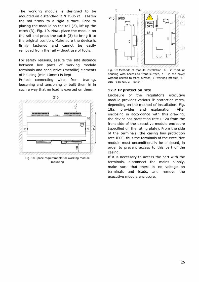
The working module is designed to be
mounted on a standard DIN TS35 rail. Fasten
the rail firmly to a rigid surface. Prior to
placing the module on the rail (2), lift up the
catch (3), Fig. 19. Now, place the module on
the rail and press the catch (3) to bring it to
the original position. Make sure the device is
firmly fastened and cannot be easily
removed from the rail without use of tools.
For safety reasons, assure the safe distance
between live parts of working module
terminals and conductive (metallic) elements
of housing (min.10mm) is kept.
Protect connecting wires from tearing,
loosening and tensioning or built them in in
such a way that no load is exerted on them.
Fig. 18 Space requirements for working module
mounting
Fig. 19 Methods of module installation: a – in modular
housing with access to front surface, b – in the cover
without access to front surface, 1- working module, 2 –
DIN TS35 rail, 3 – catch.
12.7 IP protection rate
Enclosure of the regulator’s executive
module provides various IP protection rates,
depending on the method of installation. Fig.
18a. provides and explanation. After
enclosing in accordance with this drawing,
the device has protection rate IP 20 from the
front side of the executive module enclosure
(specified on the rating plate). From the side
of the terminals, the casing has protection
rate IP00, thus the terminals of the executive
module must unconditionally be enclosed, in
order to prevent access to this part of the
casing.
If it is necessary to access the part with the
terminals, disconnect the mains supply,
make sure that there is no voltage on
terminals and leads, and remove the
executive module enclosure.

27
12.8 Connecting electrical system
Regulator is designed to be fed with 230V~, 50Hz voltage. The electrical system should be:
three core (with protective wire),
in accordance with applicable regulations.
Caution: After the regulator is turned off using the keyboard, dangerous voltage can
occur on the terminals. Before starting any assembly works, you must disconnect the
mains supply and make sure that there is no dangerous voltage on the terminals and
the leads.
The connection wires should not have contact with surfaces of temperature exceeding the
nominal temperature of their operation.
Terminals number 1-15 are intended only for connecting devices with mains supply 230V~.
Terminals 16-31 are intended for cooperation with low voltage devices (below 12 V).
Connecting mains supply 230V~ to terminals 16-31 and to transmission
connectors RS485 will damage the regulator and creates risk of an electric
shock!
Tips of the connected wires, especially power leads, must be secured against splitting by means
of insulated clamp sleeves.
Connect power supply wires to terminals indicated with an arrow.
All peripherals (such like: pumps, RE-marked relays and connected recipients) may be
connected only by qualified persons in accordance with applicable regulations. Safety
precautions to prevent electrocution should be observed.
Regulator should be equipped with a set of pins connected to the 230V AC mains.
Connect protective wire of power supply cable to ground strip linked with metal boiler housing.
Connect coupling to the terminal of the regulator indicated with a sign and to earthing
terminals of devices connected to the regulator, Fig. 20.
28
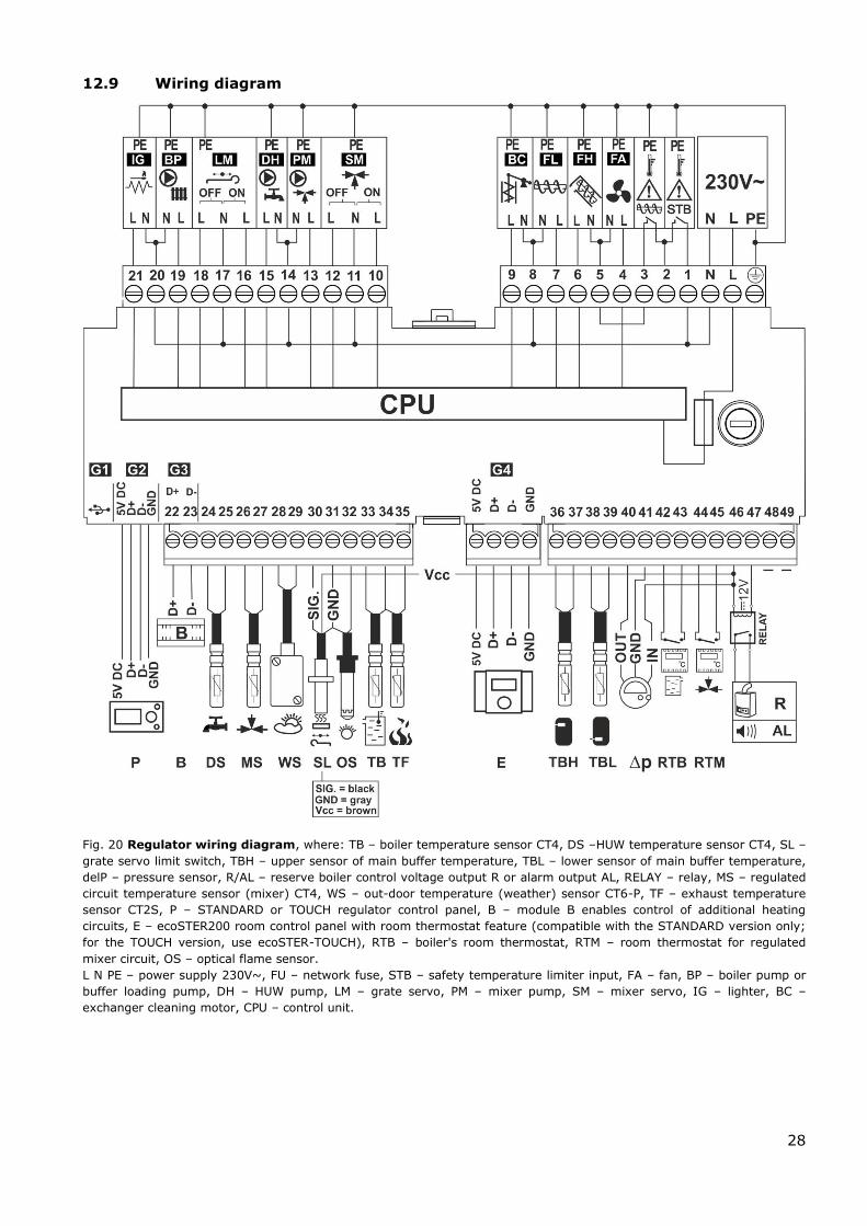
12.9 Wiring diagram
Fig. 20 Regulator wiring diagram, where: TB – boiler temperature sensor CT4, DS –HUW temperature sensor CT4, SL –
grate servo limit switch, TBH – upper sensor of main buffer temperature, TBL – lower sensor of main buffer temperature,
delP – pressure sensor, R/AL – reserve boiler control voltage output R or alarm output AL, RELAY – relay, MS – regulated
circuit temperature sensor (mixer) CT4, WS – out-door temperature (weather) sensor CT6-P, TF – exhaust temperature
sensor CT2S, P – STANDARD or TOUCH regulator control panel, B – module B enables control of additional heating
circuits, E – ecoSTER200 room control panel with room thermostat feature (compatible with the STANDARD version only;
for the TOUCH version, use ecoSTER-TOUCH), RTB – boiler's room thermostat, RTM – room thermostat for regulated
mixer circuit, OS – optical flame sensor.
L N PE – power supply 230V~, FU – network fuse, STB – safety temperature limiter input, FA – fan, BP – boiler pump or
buffer loading pump, DH – HUW pump, LM – grate servo, PM – mixer pump, SM – mixer servo, IG – lighter, BC –
exchanger cleaning motor, CPU – control unit.
29
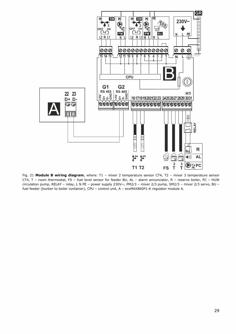
Fig. 21 Module B wiring diagram, where: T1 – mixer 2 temperature sensor CT4, T2 – mixer 3 temperature sensor
CT4, T – room thermostat, FS – fuel level sensor for feeder BU, AL – alarm annunciator, R – reserve boiler, PC – HUW
circulation pump, RELAY – relay, L N PE – power supply 230V~, PM2/3 – mixer 2/3 pump, SM2/3 – mixer 2/3 servo, BU –
fuel feeder (bunker to boiler container), CPU – control unit, A – ecoMAX860P1-K regulator module A.

30
12.10 Connection of temperature
sensors
Sensor wires may be extended using wires of
cross-section area not less than 0.5 mm2.
Total length of wires of each sensor should
not exceed 15 m.
Insert boiler temperature sensor into
thermometer well fastened to boiler shell.
Fasten feeder temperature sensor to the
surface of feeder screw tube. Insert
temperature sensor of HUW container into
thermometer well welded to the container.
The best way to mount mixer temperature
sensor is to insert it into a sleeve located in
the stream of flowing water, however, it is
also allowed to fasten the sensor in a contact
manner provided that the sensor and the
pipe are properly heat-insulated.
Sensors shall be protected against
loosening from surfaces they are
mounted to.
Make sure thermal contact between the
sensors and the surface which temperature is
measured is good. Apply thermal paste to
improve the contact. Pouring sensors with oil
or water is not allowed. Sensor wires should
be separated from power supply wires.
Otherwise, temperature indications may be
erroneous. Min. distance between these
wires should be 10 cm.
Do not allow sensor wires to contact hot
parts of the boiler and heating system. Wires
of temperature sensors are heat resistant to
the temperature not exceeding 100°C.
12.11 Connecting weather sensor
The regulator cooperates only with a weather
sensor of the CT4-P type. The sensor should
be installed on the coldest wall of the
building, usually this is the northern wall,
under a roof. The sensor should not be
exposed to direct sunlight and rain. The
sensor should be fitted at least 2 m above
the ground, far from windows, chimneys and
other heat sources which could disturb the
temperature measurement (at least 1,5 m).
Connect the sensor using cable of 0,5 mm2
cross-section, up to 25 m long. Polarity of
the leads is insignificant. Connect the other
end of the cable to the regulator.
Attach the sensor to the wall using tackbolts.
To access the tackbolts holes, unscrew the
sensor lid.
Fig. 22 Connecting weather senor CT4-P.
12.12 Checking temperature sensors
Temperature sensors CT4/CT4-P/CT2S can
be checked by measuring their resistance at
the given temperature. In the case of finding
significant differences between the value of
measured resistance and the values
presented in the table below, the sensor
must be changed.
CT4
Ambient
temp. °C
Min.
Ω
Rated
Ω
Max.
Ω
0 802 815 828
10 874 886 898
20 950 961 972
25 990 1000 1010
30 1029 1040 1051
40 1108 1122 1136
50 1192 1209 1225
60 1278 1299 1319
70 1369 1392 1416
80 1462 1490 1518
90 1559 1591 1623
100 1659 1696 1733
exhaust CT2S-2, CT6-P
Temp.
°C
Min.
Ω
Rated
Ω
Max.
Ω
0 999.7 1000.0 1000.3
25 1096.9 1097.3 1097.7
50 1193.4 1194.0 1194.6
100 1384.2 1385.0 1385.8
125 1478.5 1479.4 1480.3
150 1572.0 1573.1 1574.2

31
12.13 Connection of mixers room
thermostat
Room thermostat with open contacts reduces
preset temperature of mixer circuit by the
decrement set in:
Menu → Mixer 1,2,3,4,5 settings, →
Mixer room thermostat
Select the value of this parameter so that
once the room thermostat has responded (its
contacts have opened), the temperature in
the room drops.
Other settings - see sec. 8.14
When connecting the ecoSTER room control
panel, make sure the Thermostat select
parameter is set to a correct value.
Menu → Service Settings → Mixer
1,2,3,4,5 settings → Thermostat select.
Details on how to connect room control
panel are given in sect. 12.19.
12.14 Connection of boiler's room
thermostat
Boiler circuit room thermostat may activate
the burner or deactivate CH boiler pump. In
order for the room thermostat to control
boiler operation, set the Thermostat select.
value to standard or ecoSTER T1 (if the
ecoSTER-TOUCH room control panel is
connected)
Menu → Service Settings → Boiler
Settings → Thermostat select.
In order for the room thermostat to control
CH pump operation (without deactivating the
boiler), set the Pump off by therm. value to
YES.
Menu → Service Settings → Boiler
Settings → Pump off by therm.
12.15 Connection of reserve boiler
The regulator can control a reserve boiler
(gas- or oil-fired), eliminating the necessity
of enabling or disabling this boiler manually.
The reserve boiler will be enabled if the
temperature of the boiler drops below
parameter:
Menu → Service Settings → H-output →
Reserve boiler activation temperature
Connection to a reserve boiler, e.g. oil-fired
one, should only be made by a qualified
fitter, in accordance with the technical
documentation of this boiler.
The reserve boiler should be connected via
relay to terminals 46-47
Fig. 23 Model diagram of layout for connecting a reserve
boiler to the ecoMAX800P1-L regulator, where: 1-
regulator ecoMAX800P1-L module B 2 – reserve boiler
(gas- or oil-fired), 3 – Module U3, consisting of relay RM
84-2012-35-1006 and base GZT80 RELPOL.
Standard version of the regulator is not
equipped with a relay.
You have to perform assembly
and installation of the module by
yourself, in conformity with the
applicable standards.
Reserve boiler control is switched off upon
setting the H-output function to the reserve
boiler.
Menu → Service Settings → H-output →
H-output function
The reserve boiler is switched on when there
is no voltage on terminals 46-47. The
reserve boiler is switched off when there is
voltage on terminals 46-47.
When the ecoMAX regulator enters
the STAND-BY mode (OFF), the
reserve boiler is automatically
switched on. The heating system
does not operate.

32
Fig. 245 Hydraulic diagram with reserve boiler, where: 1
– regulator, 2 – reserve boiler, 3 – relay (Fig. 25), 4 –
switching valve (with limit switches).
Fig. 25 Wiring diagram of control of the switching valve
in the reserve boiler, where: 1 – ecoMAX860P1-K
regulator, 2 – reserve boiler, 3 – relay, 5 – switching
valve servo (with limit switches). Note: terminals
5 The presented hydraulic diagram does not replace
central heating engineering design and may be used for
information purposes only.
22,21,24 have to be galvanically insulated from
terminals 12,11,14.
12.16 Connection of alarm signalling
Regulator may announce alarm conditions by
activating an external device (e.g. a bell or
GSM device to send a text message).
Connect alarm annunciator as shown in Fig.
26 through the relay.
Alarm signalling may be deactivated by
setting the H-output function to alarms.
Menu → Service Settings → H-output →
H-output function
Fig. 26 Connection of an external alarm annunciator. 1-
regulator , 2 – external alarm annunciator, 3 – relay.
Have the relay installed by a
qualified technician in line with
current regulations.
Then, select the alarms for which the signal
output should be activated for the system to
operate correctly:
Menu → Service Settings → H-output →
Alarms
Alarms are described in sect. 15.
33
12.17 Connection of mixer
When connecting mixer servo,
take due care to prevent boiler
overheating, which may occur
when the flow of boiler water is
limited. You are advised to get
familiar with the position of the
valve corresponding to its
maximum opening before
commencement of work so that
you may ensure heat collection
from the boiler at any time it is
required by opening it completely.
The regulator works only with mixing valve
servos equipped with limit switches. Use of
other servos is not allowed. The servos of full
turn time from 30 to 255 s may be used.
Description of mixer connection:
Description of mixer connection:
- connect mixer temperature sensor, -
connect mixer pump wiring,
- switch on the regulator and select proper
mixer support in the service menu
MENU SERVICE SETTINGS Mixer 1
Settings
- enter the proper Valve Opening Time in
Service Settings (this time should be
indicated on servo rating plate e.g. 120 s).
- connect power supply to the regulator and
switch on the regulator to start the mixer
pump,
- determine direction of servo closing/
opening. For this purpose, set the selector
located on the housing of the servo to
manual control and find the positions in
which the temperature in mixer circuit is
maximum and minimum (it corresponds to
the setting of the regulator of "100% ON"
and "0% OFF, respectively). Note the
position to verify the connections later,
- disconnect power supply to the regulator,
- connect mixer servo and regulator wiring
according to valve servo manufacturer's
technical documentation. Do not mistake
direction of valve opening with its closing,
- connect regulator power supply and put it
in the STAND-BY mode,
- check whether wires to mixer closing and
opening are not interchanged. To do this,
enter MENU Manual control and open the
mixer by selecting Mix1 Open = ON. When
opening the servo, the temperature on mixer
sensor should increase. If not, disconnect
regulator power supply and switch the wires.
(Note: other reason may be incorrect
mechanical connection of the valve! – refer
to the documentation of valve manufacturer
and check whether the valve is properly
connected).
12.18 Connecting temperature limiter
STB
In order to prevent the boiler from
overheating due to the regulator
malfunction, an STB safety temperature
limiter, or any other appropriate for the
given boiler and heating system, should be
fitted. When the STB is activated, the fan
and fuel feeder motors are disabled.
The STB must have nominal
operating voltage of at least
~230V, and have the applicable
certifications.
12.19 Connecting room panel
The regulator can be equipped with room
panel ecoSTER200, which can serve as:
- room thermostat (supporting up to 3
thermostats),
- boiler control panel,
- alarm signalling device,
- fuel level indicator.
Note: Cross-section area of
wires used to connect ecoSTER-
TOUCH control panel should be:
- 0,5mm2 for ecoSTER200
- 0,75mm2 for ecoSTER-TOUCH
Max. length of wires should not exceed 30 m.
This length may be longer if the wires used
have cross-section area larger than
0.75mm2.
Four-conductor connection:
How to connect – see Fig. 25
Two-conductor connection:
For two-wire connection, power supply of 5 V
DC and rated current of min. 500 mA is
required. Points to supply ecoSTER-TOUCH:
34
Connect GND and +5 V to external source of
supply6. Connect lines D+ and D- acc. wiring
diagram Fig. 25.
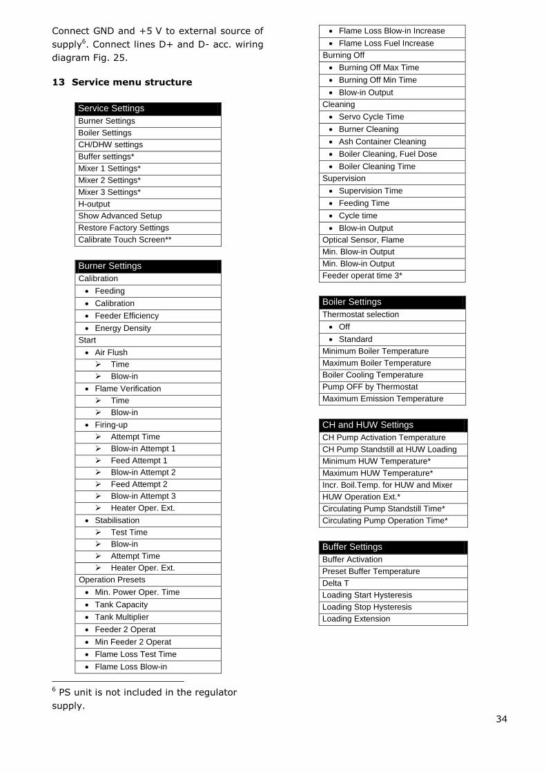
13 Service menu structure
Service Settings
Burner Settings
Boiler Settings
CH/DHW settings
Buffer settings*
Mixer 1 Settings*
Mixer 2 Settings*
Mixer 3 Settings*
H-output
Show Advanced Setup
Restore Factory Settings
Calibrate Touch Screen**
Burner Settings
Calibration
Feeding
Calibration
Feeder Efficiency
Energy Density
Start
Air Flush
Time
Blow-in
Flame Verification
Time
Blow-in
Firing-up
Attempt Time
Blow-in Attempt 1
Feed Attempt 1
Blow-in Attempt 2
Feed Attempt 2
Blow-in Attempt 3
Heater Oper. Ext.
Stabilisation
Test Time
Blow-in
Attempt Time
Heater Oper. Ext.
Operation Presets
Min. Power Oper. Time
Tank Capacity
Tank Multiplier
Feeder 2 Operat
Min Feeder 2 Operat
Flame Loss Test Time
Flame Loss Blow-in
6 PS unit is not included in the regulator
supply.
Flame Loss Blow-in Increase
Flame Loss Fuel Increase
Burning Off
Burning Off Max Time
Burning Off Min Time
Blow-in Output
Cleaning
Servo Cycle Time
Burner Cleaning
Ash Container Cleaning
Boiler Cleaning, Fuel Dose
Boiler Cleaning Time
Supervision
Supervision Time
Feeding Time
Cycle time
Blow-in Output
Optical Sensor, Flame
Min. Blow-in Output
Min. Blow-in Output
Feeder operat time 3*
Boiler Settings
Thermostat selection
Off
Standard
Minimum Boiler Temperature
Maximum Boiler Temperature
Boiler Cooling Temperature
Pump OFF by Thermostat
Maximum Emission Temperature
CH and HUW Settings
CH Pump Activation Temperature
CH Pump Standstill at HUW Loading
Minimum HUW Temperature*
Maximum HUW Temperature*
Incr. Boil.Temp. for HUW and Mixer
HUW Operation Ext.*
Circulating Pump Standstill Time*
Circulating Pump Operation Time*
Buffer Settings
Buffer Activation
Preset Buffer Temperature
Delta T
Loading Start Hysteresis
Loading Stop Hysteresis
Loading Extension
35
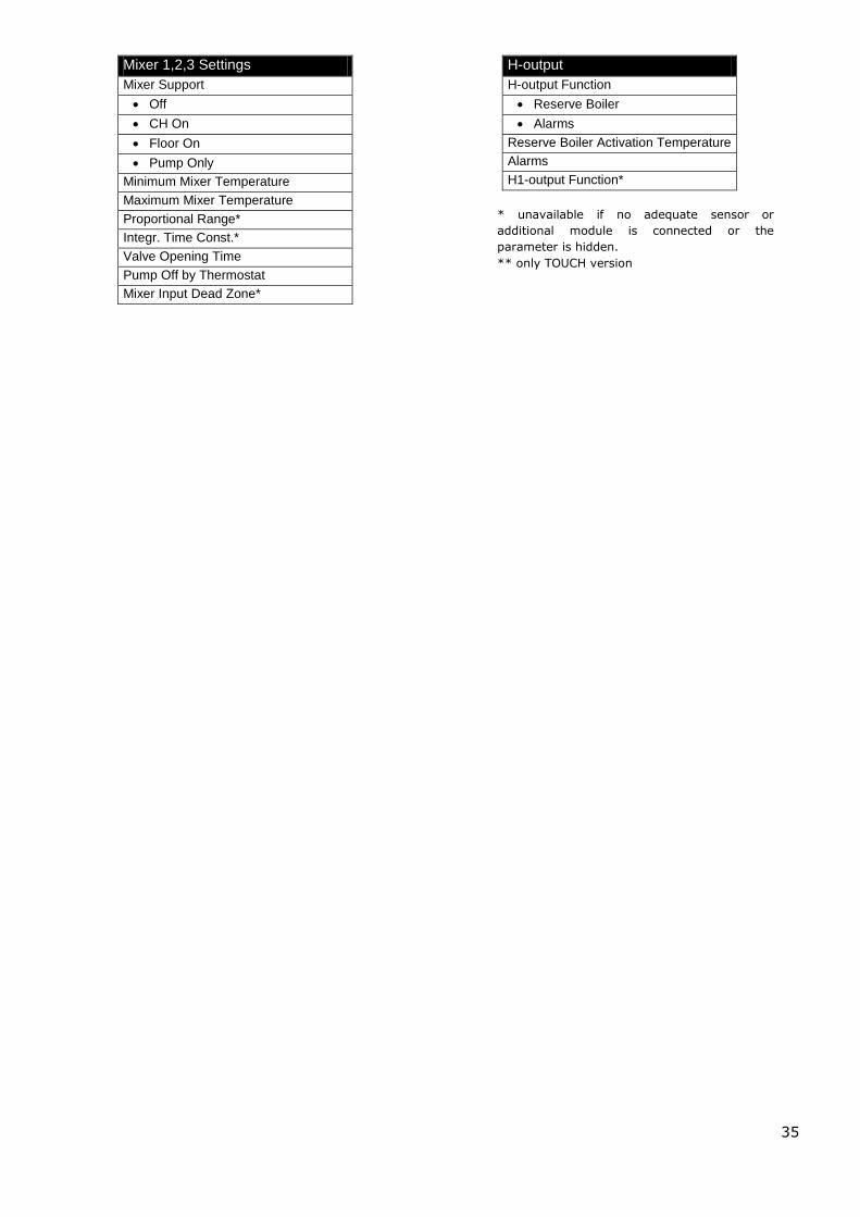
Mixer 1,2,3 Settings
Mixer Support
Off
CH On
Floor On
Pump Only
Minimum Mixer Temperature
Maximum Mixer Temperature
Proportional Range*
Integr. Time Const.*
Valve Opening Time
Pump Off by Thermostat
Mixer Input Dead Zone*
H-output
H-output Function
Reserve Boiler
Alarms
Reserve Boiler Activation Temperature
Alarms
H1-output Function*
* unavailable if no adequate sensor or
additional module is connected or the
parameter is hidden.
** only TOUCH version
36
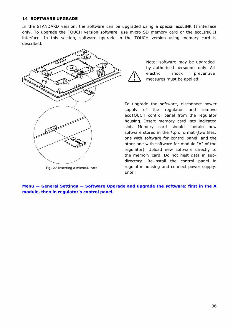
14 SOFTWARE UPGRADE
In the STANDARD version, the software can be upgraded using a special ecoLINK II interface
only. To upgrade the TOUCH version software, use micro SD memory card or the ecoLINK II
interface. In this section, software upgrade in the TOUCH version using memory card is
described.
Note: software may be upgraded
by authorised personnel only. All
electric shock preventive
measures must be applied!
To upgrade the software, disconnect power
supply of the regulator and remove
ecoTOUCH control panel from the regulator
housing. Insert memory card into indicated
slot. Memory card should contain new
software stored in the *.pfc format (two files:
one with software for control panel, and the
other one with software for module "A" of the
regulator). Upload new software directly to
the memory card. Do not nest data in sub-
directory. Re-install the control panel in
regulator housing and connect power supply.
Enter:
Menu → General Settings → Software Upgrade and upgrade the software: first in the A
module, then in regulator's control panel.
Fig. 27 Inserting a microSD card
37
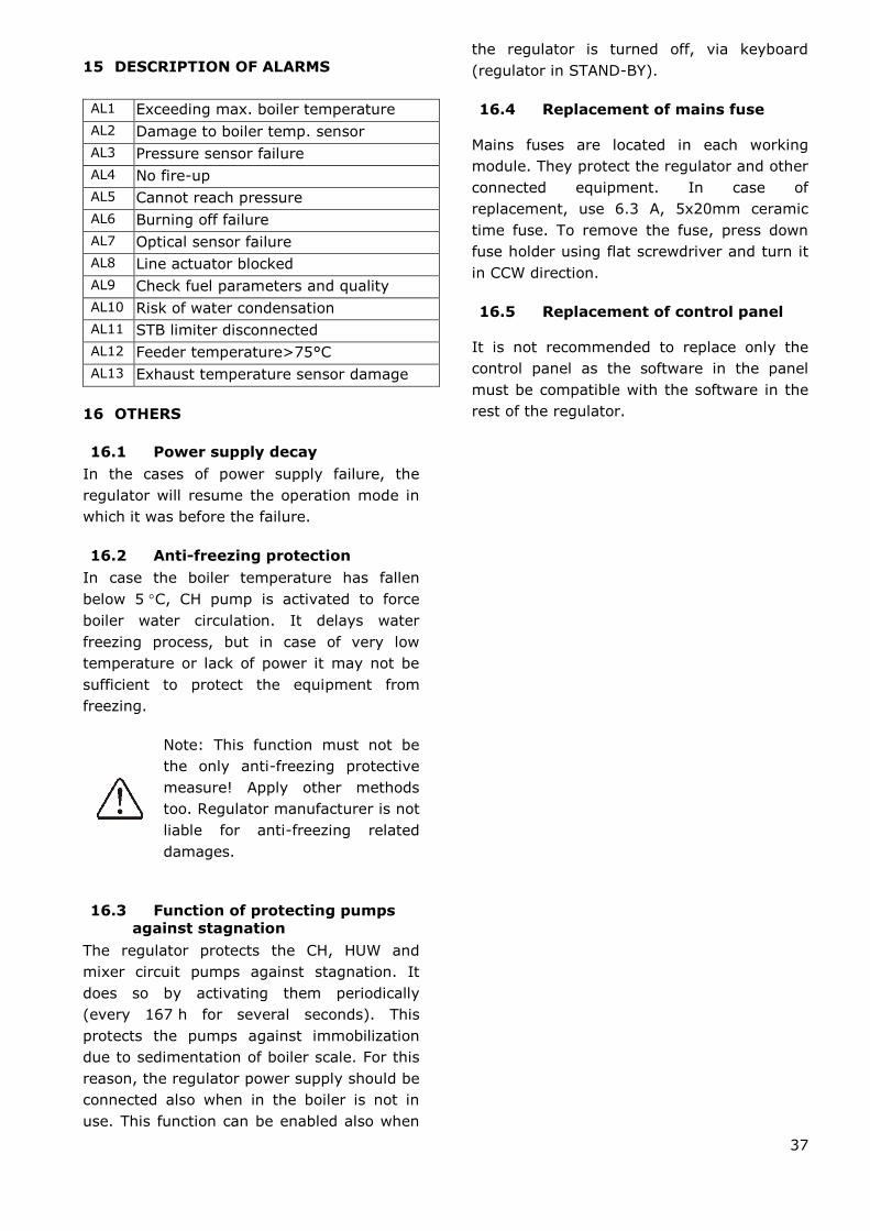
15 DESCRIPTION OF ALARMS
AL1 Exceeding max. boiler temperature
AL2 Damage to boiler temp. sensor
AL3 Pressure sensor failure
AL4 No fire-up
AL5 Cannot reach pressure
AL6 Burning off failure
AL7 Optical sensor failure
AL8 Line actuator blocked
AL9 Check fuel parameters and quality
AL10 Risk of water condensation
AL11 STB limiter disconnected
AL12 Feeder temperature>75°C
AL13 Exhaust temperature sensor damage
16 OTHERS
16.1 Power supply decay
In the cases of power supply failure, the
regulator will resume the operation mode in
which it was before the failure.
16.2 Anti-freezing protection
In case the boiler temperature has fallen
below 5 C, CH pump is activated to force
boiler water circulation. It delays water
freezing process, but in case of very low
temperature or lack of power it may not be
sufficient to protect the equipment from
freezing.
Note: This function must not be
the only anti-freezing protective
measure! Apply other methods
too. Regulator manufacturer is not
liable for anti-freezing related
damages.
16.3 Function of protecting pumps
against stagnation
The regulator protects the CH, HUW and
mixer circuit pumps against stagnation. It
does so by activating them periodically
(every 167 h for several seconds). This
protects the pumps against immobilization
due to sedimentation of boiler scale. For this
reason, the regulator power supply should be
connected also when in the boiler is not in
use. This function can be enabled also when
the regulator is turned off, via keyboard
(regulator in STAND-BY).
16.4 Replacement of mains fuse
Mains fuses are located in each working
module. They protect the regulator and other
connected equipment. In case of
replacement, use 6.3 A, 5x20mm ceramic
time fuse. To remove the fuse, press down
fuse holder using flat screwdriver and turn it
in CCW direction.
16.5 Replacement of control panel
It is not recommended to replace only the
control panel as the software in the panel
must be compatible with the software in the
rest of the regulator.

17 Revision history
Issue 1.1 – Changed Fig. 20


Ignatki 27a, 16-001 Kleosin Poland
phone +48 85 749-70-00 fax +48 85 749-70-14
www.plum.pl
www.plumelectronics.eu