boiler installation instructions for ru 1s … · boiler section onto the inserted nipples until...
TRANSCRIPT
11/07/00
BOILER INSTALLATION INSTRUCTIONS FOR RU 1S / BRU 1 RU 2S / BRU 2 RU 3S
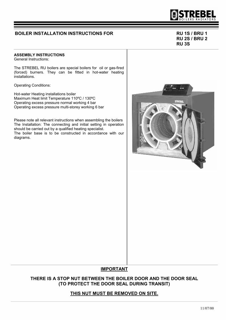
ASSEMBLY INSTRUCTIONS General Instructions: The STREBEL RU boilers are special boilers for oil or gas-fired (forced) burners. They can be fitted in hot-water heating installations. Operating Conditions: Hot-water Heating installations boiler Maximum Heat limit Temperature 110ºC / 130ºC Operating excess pressure normal working 4 bar Operating excess pressure multi-storey working 6 bar Please note all relevant instructions when assembling the boilers The Installation: The connecting and initial setting in operation should be carried out by a qualified heating specialist. The boiler base is to be constructed in accordance with our diagrams.
IMPORTANT
THERE IS A STOP NUT BETWEEN THE BOILER DOOR AND THE DOOR SEAL (TO PROTECT THE DOOR SEAL DURING TRANSIT)
THIS NUT MUST BE REMOVED ON SITE.

ASSEMBLY INSTRUCTIONS FOR:
Page 2 11/07/00
CONTENTS:
Assembly instructions & tools
Boiler base details & Important assembly advice
Wall clearance dimensions
Pulling up sections
Pulling up sections
Positioning & Influence of baffles
Diagram of RU1 injector tube
Fitting the flue-gas collector hood
Fitting the rear wall protective refractory
Converting the burner door hinge
Assembly of boiler connections
Assembling the jackets and insulation
BRU 1s Bicalor assembly completion
BRU 1s Bicalor jacket & insulation assembly
Assembling the burner
Gas connections
Opening & closing burner door
Wiring details for control panel
RU 2s Assembly section
Fig. 1.2 through to Fig. 8.2 with corresponding notes
RU 2s Jacket assembly
RU 3s Assembly section
Fig. 1.3 through to Fig. 8.3 with corresponding notes
RU 3s Jacket assembly
Page :
3
4
5
6
7
8
9
10
10
10
11
12
13
14
15
16
17
18
22 & 23
27 & 28

ASSEMBLY INSTRUCTIONS FOR:
Page 3 11/07/00
ASSEMBLY INSTRUCTIONS Please follow the installation instructions very carefully. The installation of all RU and BRU boilers are very similar through the RU 1, RU 2, RU 3, & BRU 1, & BRU 2. For all installations please follow the instructions for the RU1 model and, if installing the RU 2 or RU 3 models, refer to the relevant information in the appendix at the rear of this manual when prompted. Information given in the appendix will allow for the differences between models and guide installers through the entire RU and BRU range of boilers. ASSEMBLY TOOL A bar pulling-up tool, which is returnable after assembly has been successfully completed, is made available for assembling the boiler block. The complete pulling-up tool RU 1S consists of the following 1) Pulling-up flange for the rear, intermediate & top front section 4) Pulling-up flange at the top front section 2.1) Basic bar 2.2) Extension 2.3) End piece 3.1) Free running ratchet spanners. 3.2) Stop pins 3.3) Pulling-up nut with thrust bearing Items needed for construction: flat chisel, mallet, brush, small round smoothing file, emery cloth, cleanser (e.g. petroleum), inspection lamp, spanner. Note: RU 2s Pulling-up tools shown in Fig. 4.2 and RU 3s tools in Fig. 8.3. Advice on the use of the Pulling-up tool. 1) The pulling-up flanges (1) at the rear section are screwed
onto the boiler flow and return connections. 2) The basic bars (2) are inserted through the openings of the
pulling-up flanges and ports so that the screw ends are situated out of the ports at the front. (The basic bars can be extended, as necessary.)
3) The pulling-up flanges (1) at the intermediate section or front section are pushed over the basic bar screw end from the front.
4) The Stop pins (3.2) are inserted at the back through one of the transverse borings of the pulling-up bar.
5) The pulling-up nuts (3.3) are screwed onto the basic bar screw end, from the front until they take up the slack on the pulling up tool flanges.
6) The free-running ratchets (3.3) are on the pulling-up nuts.
Pulling-up Tools
Using Pulling-up Tools
ASSEMBLY INSTRUCTIONS FOR: RU 1s Assembly

ASSEMBLY INSTRUCTIONS FOR:
Page 4 11/07/00
Boiler base The boiler base is to be constructed in accordance with the base plans. The boiler block may stand on an iron frame set in concrete but is not essential. The boiler must stand on a level non-combustible base which is capable of adequately supporting the weight of the boiler, water content and any ancillary equipment. (Dimensions for optional TICO Sound reducing framework shown opposite). (Fig 2.2 & Fig 3.2 are for RU 2s and Fig 2.3 & Fig 3.3 are for RU 3s). Important Assembly Advice: Please read through before starting the assembly! The boiler is normally delivered in individual sections, which are assembled on site as a boiler block using tapered nipples. The individual weights of the boiler components are as follows: Rear section approx. 195kg Intermediate section approx. 185kg Front section with burner door approx. 285kg Front section without burner door approx. 192kg Burner door approx. 93kg Flue gas collection housing approx. 39kg
NOTE: Weights for RU 2s (Fig 1.2) & RU 3s (Fig 1.3) are shown in appendix at rear.
The watertight joint between two boiler sections is a high-precision press fit between the boiler nipple and nipple port. The block assembly must be carried out accordingly with precision. The following points should be observed during assembly: No damage to the nipple and borings should be apparent. Before a nipple is inserted and a section fitted, the nipple and the boring should be inspected. Any damage, e.g. to the face of the boring, destroys the nipple seal and leads to leakage. Attention! Slight damage (transport damage) to the faces of the boiler nipple or to the nipple ports (A) can be corrected with a small smoothing file and emery cloth without affecting the water tightness of the joint. − The accompanying nipple jointing oil sealing compound
serves as a lubricant as well as a waterproof seal and must be used.
− During the assembly no dirt should be allowed to remain on the nipples or in the boring. These should be inspected during each assembly phase, but particularly before fixing on the pulling-up flanges. Particles of dirt, which are not removed, can lead to leakage.
− During the boiler block assembly take care that the various boiler sections are fitted to the various positions, depending on the model.
− Boiler nipples and nipple ports must align exactly at all stages of the assembly. An inclined inserted nipple leads to leakage.
In addition, certain specific points should be observed at each stage.
Diagram showing nipple and boring.
Thickness of base = 60mm min.
Base Dimensions
A B
RU 1s-4 1350 440
RU 1s-5 1550 640
RU 1s-6 1750 840
RU 1s-7 1950 1040
RU 1s-8 2150 1240
RU 1s-9 2350 1440
Thickness = 20mm
TICO Sound reducing framework
A B
RU 1s-4 780 420
RU 1s-5 980 620
RU 1s-6 1180 820
RU 1s-7 1380 1020
RU 1s-8 1580 1220
RU 1s-9 1780 1420
ASSEMBLY INSTRUCTIONS FOR: RU 1s Assembly
ASSEMBLY INSTRUCTIONS FOR:
Page 5 11/07/00
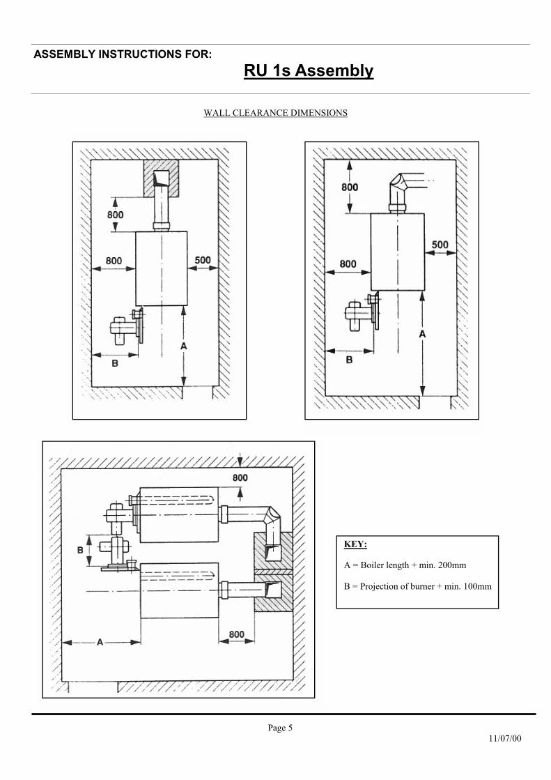
WALL CLEARANCE DIMENSIONS
KEY: A = Boiler length + min. 200mm B = Projection of burner + min. 100mm
ASSEMBLY INSTRUCTIONS FOR: RU 1s Assembly

ASSEMBLY INSTRUCTIONS FOR:
Page 6 11/07/00
Stage 1: Drive nipple into nipple port with care Inspect nipple and nipple port for damage. Smear nipple jointing oil sealing compound over nipple and boring. Gently drive nipple into flow and return nipple ports using a mallet or synthetic hammer. The nipples must remain firm and exactly vertical in the nipple ports and must be able to take the next boiler section without twisting from nipple ports. Take care, twisted nipples lead to leakage. Stage 2: Before offering up the boiler section to both inserted nipples. Inspect nipple and nipple port for damage. Smear nipple jointing oil sealing compound over nipple and nipple port. Place boiler mastic sealing strand into sealing grooves as shown in diagram opposite (see Fig. 6.2 For RU 2s and Fig. 7.3 For RU 3s). Place boiler section in front of both inserted nipples. Raise the boiler section onto the inserted nipples using a flat chisel under the section feet. The inserted nipples must stand approx. 1 to 2 mm higher than the boring of the section, which is to be joined. Using a crowbar, raise the boiler section onto the inserted nipples until nipple and nipple ports mate and hold. Inspect boring once again for any dirt deposits before fixing the pulling-up flanges. Remove dirt deposits if necessary. Stage 3: To assemble boiler sections using pulling-up tool. Take care during the pulling-up process that the clearance between both boiler and section is even. If the clearance is uneven insert a flat chisel into the narrow point and continue pulling-up until the clearance is even again.
Driving Nipple into Boring
Diagram showing mastic placement
Raising sections to ensure nipples and borings mate
ASSEMBLY INSTRUCTIONS FOR: RU 1s Assembly
ASSEMBLY INSTRUCTIONS FOR:
Page 7 11/07/00
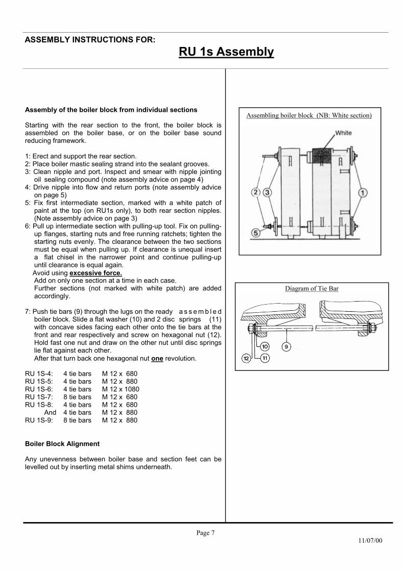
Assembly of the boiler block from individual sections Starting with the rear section to the front, the boiler block is assembled on the boiler base, or on the boiler base sound reducing framework. 1: Erect and support the rear section. 2: Place boiler mastic sealing strand into the sealant grooves. 3: Clean nipple and port. Inspect and smear with nipple jointing oil sealing compound (note assembly advice on page 4) 4: Drive nipple into flow and return ports (note assembly advice on page 5) 5: Fix first intermediate section, marked with a white patch of paint at the top (on RU1s only), to both rear section nipples. (Note assembly advice on page 3) 6: Pull up intermediate section with pulling-up tool. Fix on pulling- up flanges, starting nuts and free running ratchets; tighten the starting nuts evenly. The clearance between the two sections must be equal when pulling up. If clearance is unequal insert a flat chisel in the narrower point and continue pulling-up until clearance is equal again. Avoid using excessive force. Add on only one section at a time in each case. Further sections (not marked with white patch) are added accordingly. 7: Push tie bars (9) through the lugs on the ready a s s e m b l e d boiler block. Slide a flat washer (10) and 2 disc springs (11) with concave sides facing each other onto the tie bars at the front and rear respectively and screw on hexagonal nut (12). Hold fast one nut and draw on the other nut until disc springs lie flat against each other. After that turn back one hexagonal nut one revolution. RU 1S-4: 4 tie bars M 12 x 680 RU 1S-5: 4 tie bars M 12 x 880 RU 1S-6: 4 tie bars M 12 x 1080 RU 1S-7: 8 tie bars M 12 x 680 RU 1S-8: 4 tie bars M 12 x 680 And 4 tie bars M 12 x 880 RU 1S-9: 8 tie bars M 12 x 880 Boiler Block Alignment Any unevenness between boiler base and section feet can be levelled out by inserting metal shims underneath.
Diagram of Tie Bar
Assembling boiler block (NB: White section)
ASSEMBLY INSTRUCTIONS FOR: RU 1s Assembly
ASSEMBLY INSTRUCTIONS FOR:
Page 8 11/07/00
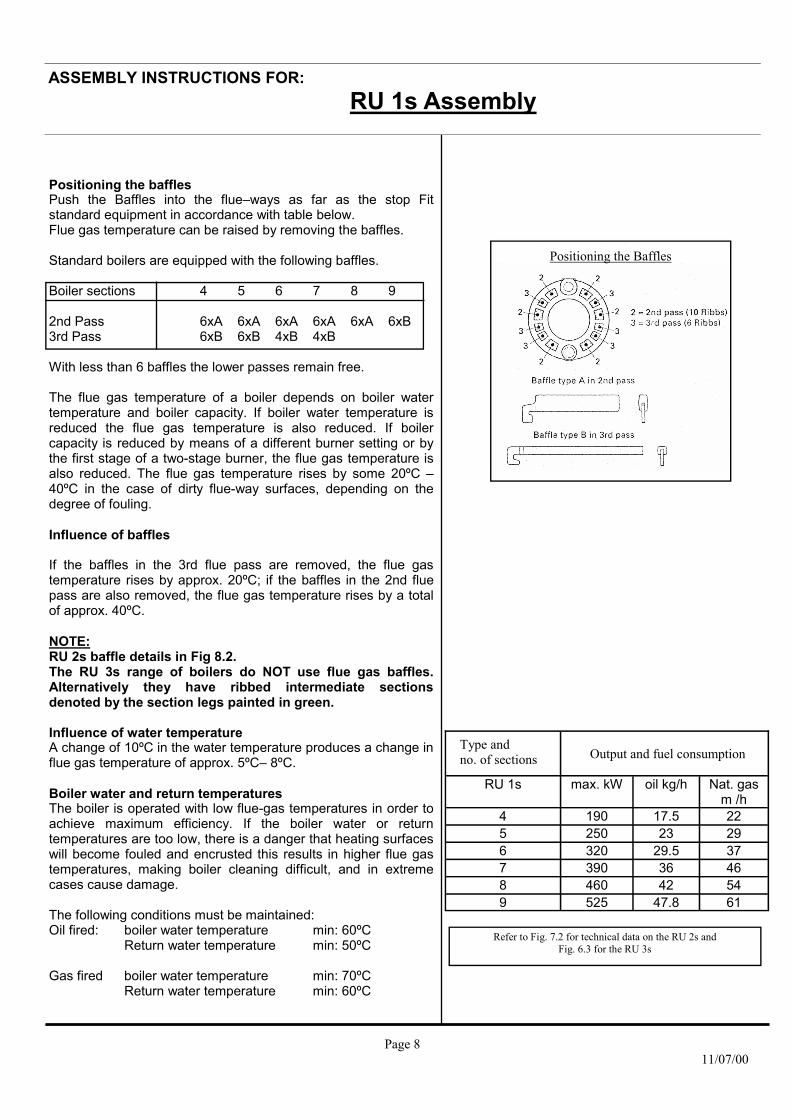
Positioning the baffles Push the Baffles into the flue–ways as far as the stop Fit standard equipment in accordance with table below. Flue gas temperature can be raised by removing the baffles. Standard boilers are equipped with the following baffles. Boiler sections 4 5 6 7 8 9 2nd Pass 6xA 6xA 6xA 6xA 6xA 6xB 3rd Pass 6xB 6xB 4xB 4xB With less than 6 baffles the lower passes remain free. The flue gas temperature of a boiler depends on boiler water temperature and boiler capacity. If boiler water temperature is reduced the flue gas temperature is also reduced. If boiler capacity is reduced by means of a different burner setting or by the first stage of a two-stage burner, the flue gas temperature is also reduced. The flue gas temperature rises by some 20ºC – 40ºC in the case of dirty flue-way surfaces, depending on the degree of fouling. Influence of baffles If the baffles in the 3rd flue pass are removed, the flue gas temperature rises by approx. 20ºC; if the baffles in the 2nd flue pass are also removed, the flue gas temperature rises by a total of approx. 40ºC. NOTE: RU 2s baffle details in Fig 8.2. The RU 3s range of boilers do NOT use flue gas baffles. Alternatively they have ribbed intermediate sections denoted by the section legs painted in green. Influence of water temperature A change of 10ºC in the water temperature produces a change in flue gas temperature of approx. 5ºC– 8ºC. Boiler water and return temperatures The boiler is operated with low flue-gas temperatures in order to achieve maximum efficiency. If the boiler water or return temperatures are too low, there is a danger that heating surfaces will become fouled and encrusted this results in higher flue gas temperatures, making boiler cleaning difficult, and in extreme cases cause damage. The following conditions must be maintained: Oil fired: boiler water temperature min: 60ºC Return water temperature min: 50ºC Gas fired boiler water temperature min: 70ºC Return water temperature min: 60ºC
RU 1s max. kW oil kg/h Nat. gas m /h
4 190 17.5 22 5 250 23 29 6 320 29.5 37 7 390 36 46 8 460 42 54 9 525 47.8 61
Type and no. of sections Output and fuel consumption
Refer to Fig. 7.2 for technical data on the RU 2s and Fig. 6.3 for the RU 3s
Positioning the Baffles
ASSEMBLY INSTRUCTIONS FOR: RU 1s Assembly

ASSEMBLY INSTRUCTIONS FOR:
Page 9 11/07/00
NOTE: Injector tube is not a requirement for the RU 2s and RU 3s boilers.
STREBEL RU 1s
Injector tube in the STREBEL RU 1s return
ASSEMBLY INSTRUCTIONS FOR: RU 1s Assembly
ASSEMBLY INSTRUCTIONS FOR:
Page 10 11/07/00
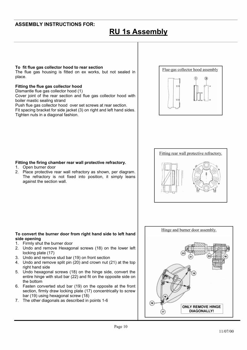
To fit flue gas collector hood to rear section The flue gas housing is fitted on ex works, but not sealed in place. Fitting the flue gas collector hood Dismantle flue gas collector hood (1) Cover joint of the rear section and flue gas collector hood with boiler mastic sealing strand Push flue gas collector hood over set screws at rear section. Fit spacing bracket for side jacket (3) on right and left hand sides. Tighten nuts in a diagonal fashion. Fitting the firing chamber rear wall protective refractory. 1. Open burner door 2. Place protective rear wall refractory as shown, per diagram.
The refractory is not fixed into position, it simply leans against the section wall.
To convert the burner door from right hand side to left hand side opening 1. Firmly shut the burner door 2. Undo and remove Hexagonal screws (18) on the lower left
locking plate (17) 3. Undo and remove stud bar (19) on front section 4. Undo and remove split pin (20) and crown nut (21) at the top
right hand side 5. Undo hexagonal screws (18) on the hinge side, convert the
entire hinge with stud bar (22) and fit on the opposite side on the bottom
6. Fasten converted stud bar (19) on the opposite at the front section, firmly draw locking plate (17) concentrically to screw bar (19) using hexagonal screw (18)
7. The other diagonals as described in points 1-6
Flue-gas collector hood assembly
Fitting rear wall protective refractory.
Hinge and burner door assembly.
ASSEMBLY INSTRUCTIONS FOR: RU 1s Assembly

ASSEMBLY INSTRUCTIONS FOR:
Page 11 11/07/00
Boiler Assembly Completion Assembly of the boiler connections - Fit blank flanges top and bottom at the front. - Fit boiler flow header to the rear at the top and boiler return
header to the rear at the bottom. Fit the 2 ½” plugs in the boiler return header Legend 1. Hexagonal screws M12 x 35 2. Supporting Washer 13/24 x 2.5 3. Blank flanges 105 4. Rubber seal 96/61 x 5 5. Hexagonal screw M16 x 40 6. Flat washer 17/30 x 3 7. Blank flange 170 8. Rubber seal 160/120 x 5 9. Rubber seal 152/115 x 5 10. Flat washer 17/30 x 3 11. Hexagonal nut M16 12. Hexagonal nut M16 13. Flat washer 17/30 x 3 14. Rubber seal 152/115 x 5 15. Weld neck flange NW100, ND6 16. Hexagonal screw M16 x 60 17. Hexagonal screw M12 x 55 18. Blank flange 105 or pre welded flange 105, NW65 19. Flat washer 13/24 x 2.5 20. Hexagonal nut M12 21. 2 x ½” plugs NOTE: RU 2s details shown in Fig. 5.2 and RU 3s details in Fig. 4.3 & Fig 5.3. Cold Water Pressure Test The assembled boiler block should be given a water pressure test of 1.3 times the excess operating pressure. The test excess pressure, however, must be at least 1 bar higher than the operating excess pressure. The highest test excess pressure is as follows: - with a normal construction 5.5 bar - with a multi-storey construction 7.8 bar
Assembly of boiler connections
ASSEMBLY INSTRUCTIONS FOR: RU 1s Assembly

ASSEMBLY INSTRUCTIONS FOR:
Page 12 11/07/00
To assemble the jackets and insulation Follow the number sequence. Floor insulation and side jackets 1. Floor insulation on right and left-hand side 125x440xL 2. Right and left hand side jackets 3. Insulation at the bottom front 50x90x990 4. Angle at the bottom front. 21x21-1156 5. Angle at the bottom rear (galv) 21x21-1156 Rear jacket insulation and rear jacket 1. Cross bar at the top rear 90x40x985 2. Flue gas housing insulation 50x180x2000 3. Rear jackets right and left hand 4. Protective metal sheet 5. Flue hood access door insulation 125x330x700 6. Flue hood access door jacket cover Boiler top insulation and front jackets 1. Cross-bar at the top front 135x40x985 2. Insulation at the top rear 125x90x990 3. Insulation at the top front 125x135x990 4. Boiler top insulation 125x1100xL 5. Instrument panel on top jacket (See instrument panel assembly instructions) 6. Boiler covering top jacket 7. Boiler front jackets right and left 8. Boiler front wall, ARF to the right 9. Sealing plate
ASSEMBLY INSTRUCTIONS FOR: RU 1s Assembly

ASSEMBLY INSTRUCTIONS FOR:
Page 13 11/07/00
10. Covering Rosette BICALOR Combination Boiler Assembly Completion The BICALOR can be fitted with top mounted calorifiers of types CS 400-9, CS 500-4, CS500-6 and CS 625-8 depending on the boiler output and the hot water requirement Assembly of calorifier - Fit blank flanges at the top and bottom front - Fit boiler flow header to the rear at the top and boiler return
header at the bottom Fit 2 ½” plugs in the boiler return header - Place calorifier support on the boiler block - Place calorifier on support - Align calorifier - Fit primary circulating pipework including pump and non
return valve ensuring it is fitted to suit direction of flow - Weld to pipework slip joint 1. Calorifier 2. Support 3. Non return valve 4. Circulating pump 5. ½” plugs in the boiler return header 6. Levelling screws 7. 2x½ “ x 150 Long immersion sensor pockets from the
instrument panel are to be fitted into the boiler flow header. If no circulating pipe has been supplied with the delivery then the piping must be constructed and made available. In addition, the non-return valve is to be fitted as per the diagram. The measurements from the centre of the pipe to the centre of the boiler (280 mm and 420 mm) must be observed. Cold Water Pressure Test The assembled boiler block should be given a water pressure test of 1.5 times the excess operating pressure. The test excess pressure, however, must be at least 1 bar higher than the operating excess pressure. The highest test excess pressure is as follows: - with a normal construction 6 bar - with a multi-storey construction 8 bar The hot water secondary side may be tested to 13 bar.
BRU 1s
BRU 1 Side View
BRU 1 Rear View

ASSEMBLY INSTRUCTIONS FOR:
Page 14 11/07/00
Assemble the jacket and insulation Floor insulation and boiler side jackets. 1. Floor insulation on right and left hand side 125x440xL 2. Right and left hand side jackets 3. Insulation at the bottom front 50x90x990 4. Angle at the bottom front 5. Angle at the bottom rear Boiler rear jacket insulation and boiler rear 1. Cross bar at the top rear 90x40x995 2. Flue gas housing insulation 50x180x2000 3. Right and left hand rear jackets 4. Protective metal sheet 5. Flue hood access door insulation 125x700x330 6. Flue hood access door jacket cover Boiler Top insulation, front jacket and rear under jacket to the calorifier 1. Cross bar at the top front 270x40x985 2. Insulation at the top rear 125x90x990 3. Boiler top insulation 125x1100xL 4. Rear under covering 5. Boiler front jacket right and left hand Fit the boiler top insulation to calorifier support through slits. Calorifier side jacket, Front and top jackets and instrument panel. 1. Calorifier side jacket right and left hand 2. Calorifier top insulation 125x960xL 3. Calorifier top jacket 4. Insulation at the front 125x270x990 5. Suspend calorifier front jacket using Straight hinge pins 6. Instrument panel on front wall (See instrument panel assembly instructions) 7. Front insulation to calorifier 50x810x980 8. Swing front calorifier jacket to closed position And secure with bent pins Calorifier rear jacket 1. Rear under jacket 2. Rear under insulation 125x500x990 3. Inner rear jacket insulation, right an left-hand 50x490x850 4. Right and left-hand rear jacket.
BRU 1s

ASSEMBLY INSTRUCTIONS FOR:
Page 15 11/07/00
Assembling the burner 1. The burner must be commissioned by a qualified combustion
engineer. Cables and pipes for electricity and oil should be fitted flexible to allow full swing of door.
2. Fit burner to burner door with a suitable burner mounting plate
3. When assembling the burner, the position of the diffuser disc (2) should be observed.
4. The largest possible diameter of the burner draught tube is limited by the boring (3) in the burner door.
5. With regard to the choice of burner, the burner head equipment stipulated by the manufacturer concerned should be used
6. Wrap burner draught tube with cerafelt fibre to insulate gap (4)
7. Electrical connection should be made according to the electrical wiring in the instrument panel and IEE regulations. Please follow operating instructions for details regarding burner setting.
The burner should only be commissioned by a Qualified Combustion Engineer.
ASSEMBLY INSTRUCTIONS FOR: RU 1s Assembly
ASSEMBLY INSTRUCTIONS FOR:
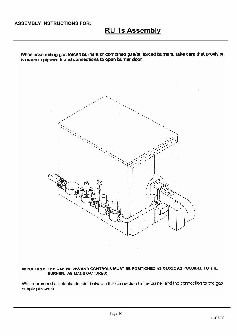
Page 16 11/07/00
ASSEMBLY INSTRUCTIONS FOR: RU 1s Assembly

ASSEMBLY INSTRUCTIONS FOR:
Page 17 11/07/00
ASSEMBLY INSTRUCTIONS FOR: RU 1s Assembly
ASSEMBLY INSTRUCTIONS FOR:
Page 18 11/07/00
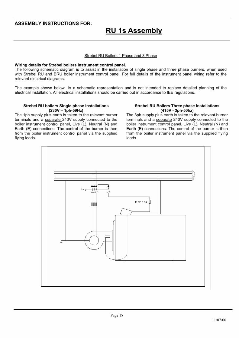
Strebel RU Boilers 1 Phase and 3 Phase Wiring details for Strebel boilers instrument control panel. The following schematic diagram is to assist in the installation of single phase and three phase burners, when used with Strebel RU and BRU boiler instrument control panel. For full details of the instrument panel wiring refer to the relevant electrical diagrams. The example shown below is a schematic representation and is not intended to replace detailed planning of the electrical installation. All electrical installations should be carried out in accordance to IEE regulations.
Strebel RU boilers Single phase Installations (230V – 1ph-59Hz)
The 1ph supply plus earth is taken to the relevant burner terminals and a separate 240V supply connected to the boiler instrument control panel, Live (L), Neutral (N) and Earth (E) connections. The control of the burner is then from the boiler instrument control panel via the supplied flying leads.
Strebel RU Boilers Three phase installations (415V - 3ph-50hz)
The 3ph supply plus earth is taken to the relevant burner terminals and a separate 240V supply connected to the boiler instrument control panel, Live (L), Neutral (N) and Earth (E) connections. The control of the burner is then from the boiler instrument panel via the supplied flying leads.
ASSEMBLY INSTRUCTIONS FOR: RU 1s Assembly

ASSEMBLY INSTRUCTIONS FOR:
Page 19 11/07/00
ASSEMBLY INSTRUCTIONS FOR: RU 2S / BRU 2S RU 2s Assembly
NOTE: RU 2s does NOT have a white patch section. Individual approximate weights of boiler components are listed in the table below: Rear section 254 kg Intermediate section 213 kg Front section with burner door 310 kg Front section without burner door 200 kg Burner door 110 kg Flue gas collection housing 50 kg
On completion of section assembly fit the 2 x ½” plugs in the boiler return header. Then fit the flow and return headers to the rear section and the blank flanges to the front section.
TICO Sound reducing framework
A B RU 2s-8 1560 1200 RU 2s-9 1760 1400
RU 2s-10 1960 1600 RU 2s-11 2160 1800 RU 2s-12 2360 2000 RU 2s-13 2560 2200 RU 2s-14 2760 2400
Fig.3.2
Fig.2.2
Fig 1.2
A B RU 2s-8 2110 1250 RU 2s-9 2310 1250 RU 2s-10 2510 1250 RU 2s-11 2710 1250 RU 2s-12 2910 1250 RU 2s-13 3110 1250 RU 2s-14 3310 1250
Boiler base details
A
B

ASSEMBLY INSTRUCTIONS FOR:
Page 20 11/07/00
Pulling-up kit Key: 1. Pulling-up flange at the top rear section 2. Pulling-up flange at the bottom rear section 3. Pulling tool for nipples 4. Pulling-up flange for intermediate sections 5. Pulling-up flange for front section 6.1 Basic bar 6.2 Extension bar 6.3 End piece bar 7. Case containing 7.1 Free-running ratchet spanner 7.2 Stop pins 7.3 Starting nut with thrust bearing. Assembly of boiler connections Legend: 1. Hexagonal screws M12 x 35 2. Supporting washer 13/24 x 2.5 3. Blank flanges 105 4. Rubber seal 95/61 x 5 5. Hexagonal screw M16 x 35 6. Flat washer 17/30 x 3 7. Blank flange 105 8. Rubber seal 207/196 x5 9. Rubber seal 95/61 x5 10. Flat washer 17/30 x3 11. Hexagonal nut M16 12. Hexagonal nut M16 13. Flat washer 17/30 x 3 14. Rubber seal 152/115 x 5 15. Weld neck flange NW 150, ND6 16. Hexagonal screw M16 x 60 17. Hexagonal screw M12 x 55 18. Blank flange 105 x 105, NW 65 19. Flat washer 13/24 x 2.5 20. Hexagonal nut M12 21. R½ plugs A pressure test, as per RU1s instructions, should be carried out.
ASSEMBLY INSTRUCTIONS FOR:
RU 2S / BRU 2S
Fig.5.2
Fig.4.2
ASSEMBLY INSTRUCTIONS FOR: RU 2S / BRU 2S RU 2s Assembly
ASSEMBLY INSTRUCTIONS FOR:
Page 21 11/07/00
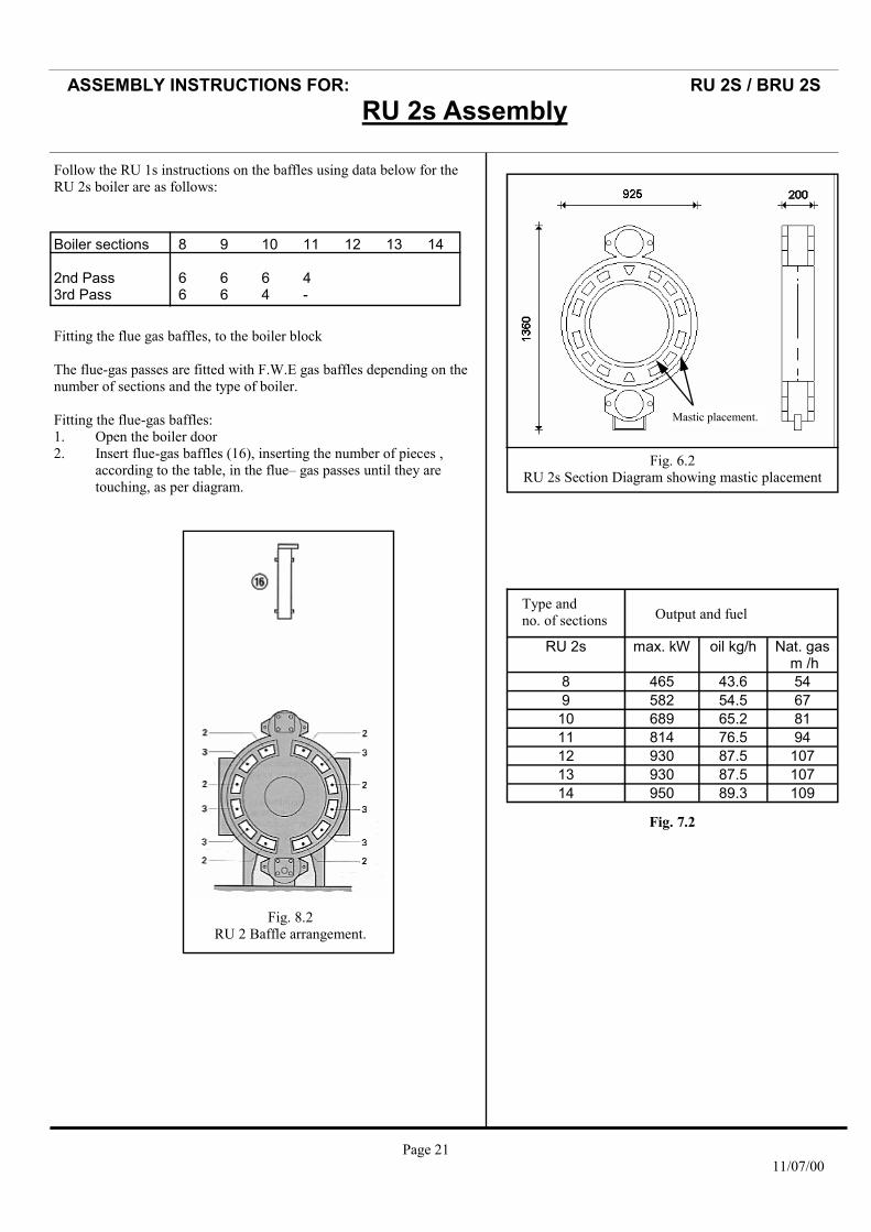
Boiler sections 8 9 10 11 12 13 14 2nd Pass 6 6 6 4 3rd Pass 6 6 4 -
Follow the RU 1s instructions on the baffles using data below for the RU 2s boiler are as follows:
Fitting the flue gas baffles, to the boiler block The flue-gas passes are fitted with F.W.E gas baffles depending on the number of sections and the type of boiler. Fitting the flue-gas baffles: 1. Open the boiler door 2. Insert flue-gas baffles (16), inserting the number of pieces ,
according to the table, in the flue– gas passes until they are touching, as per diagram.
Fig. 8.2 RU 2 Baffle arrangement.
RU 2s max. kW oil kg/h Nat. gas m /h
8 465 43.6 54 9 582 54.5 67 10 689 65.2 81 11 814 76.5 94 12 930 87.5 107 13 930 87.5 107 14 950 89.3 109
Type and no. of sections Output and fuel
Fig. 7.2
ASSEMBLY INSTRUCTIONS FOR: RU 2S / BRU 2S
Fig. 6.2 RU 2s Section Diagram showing mastic placement
Mastic placement.
ASSEMBLY INSTRUCTIONS FOR: RU 2S / BRU 2S RU 2s Assembly

ASSEMBLY INSTRUCTIONS FOR:
Page 22 11/07/00
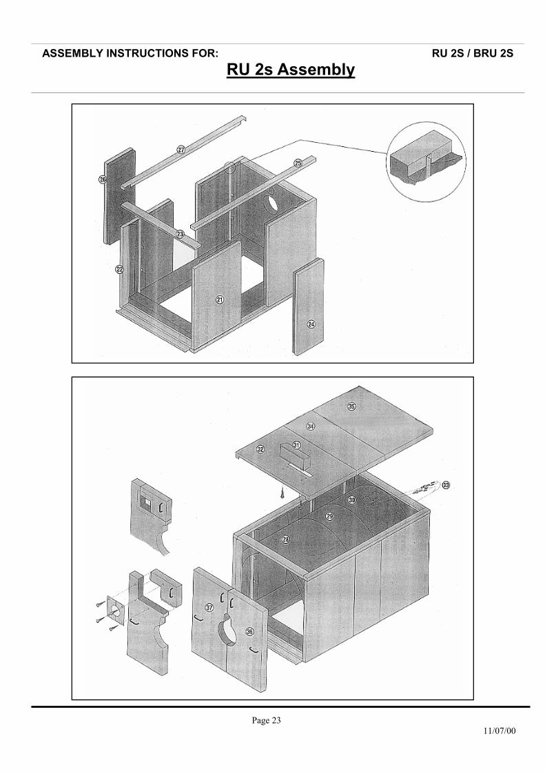
Follow the number order for jacket assembly completion
ASSEMBLY INSTRUCTIONS FOR: RU 2S / BRU 2S RU 2s Assembly
ASSEMBLY INSTRUCTIONS FOR:
Page 23 11/07/00
ASSEMBLY INSTRUCTIONS FOR: RU 2S / BRU 2S RU 2s Assembly
ASSEMBLY INSTRUCTIONS FOR:
Page 24 11/07/00
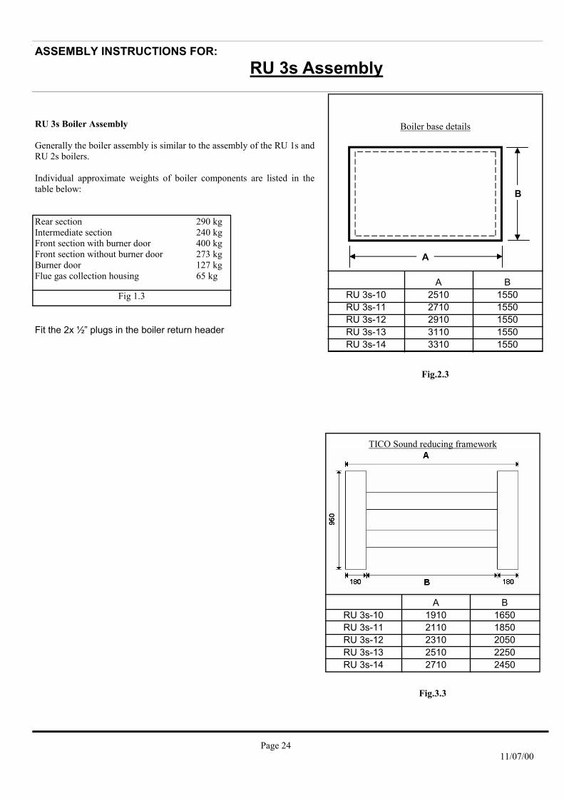
RU 3s Boiler Assembly Generally the boiler assembly is similar to the assembly of the RU 1s and RU 2s boilers. Individual approximate weights of boiler components are listed in the table below: Rear section 290 kg Intermediate section 240 kg Front section with burner door 400 kg Front section without burner door 273 kg Burner door 127 kg Flue gas collection housing 65 kg
Fit the 2x ½” plugs in the boiler return header
ASSEMBLY INSTRUCTIONS FOR:
ASSEMBLY INSTRUCTIONS FOR: RU 3s Assembly
TICO Sound reducing framework
A B RU 3s-10 1910 1650 RU 3s-11 2110 1850 RU 3s-12 2310 2050 RU 3s-13 2510 2250 RU 3s-14 2710 2450
Fig.3.3
Fig.2.3
Fig 1.3 A B
RU 3s-10 2510 1550 RU 3s-11 2710 1550 RU 3s-12 2910 1550 RU 3s-13 3110 1550 RU 3s-14 3310 1550
Boiler base details
A
B

ASSEMBLY INSTRUCTIONS FOR:
Page 25 11/07/00
Assembly of boiler connections. Legend (Fig. 4.3) 1. Door 2. Tapered centre pins 3. Door closing bolts 4. Channel jacking bracket 5. Hinge pins 6. Jacking bolts 7. Holding pins 8. Jacking bolts 9. Flange bolts 10. Blank flange and joint gasket 11. Blank flange and joint gasket 12. Slotted hinge bracket (Fig. 5.3) 12. Small sound absorbing inserts 13. Cleaning covers 14. Large section of sound absorber. 15. Flue gas collector hood 16. Flow 17. Return 18. Thermostat sensor pockets Continue to pressure test as per RU 1s instructions.
ASSEMBLY INSTRUCTIONS FOR:
Fig. 4.3
Fig. 5.3
ASSEMBLY INSTRUCTIONS FOR: RU 3s Assembly

ASSEMBLY INSTRUCTIONS FOR:
Page 26 11/07/00
ASSEMBLY INSTRUCTIONS FOR: RU 3S
Fig. 7.3 RU 3s Section diagram showing mastic placement
RU 3s max. kW oil kg/h Nat. gas m³/h
10 1050 96 122 11 1160 106 135 12 1280 117 149 13 1395 128 162 14 1400 128 165
Type and no. of sections Output and fuel consumption
Fig. 6.3
Pulling-up kit (Fig. 8.3) Key: 1. Pulling-up flange at the top rear section 2. Pulling-up flange at the bottom rear section 3. Nipple flange 4. Pulling-up flange for intermediate setions 5. Pulling-up flange for front section 6.1 Basic bar 6.2 Extension bar 6.3 End piece bar 7.1 Free-running ratchet spanner 7.2 Stop pins 7.3 Starting nut with thrust bearing
Fig.8.3
ASSEMBLY INSTRUCTIONS FOR: RU 3s Assembly

ASSEMBLY INSTRUCTIONS FOR:
Page 27 11/07/00
ASSEMBLY INSTRUCTIONS FOR: RU 3S
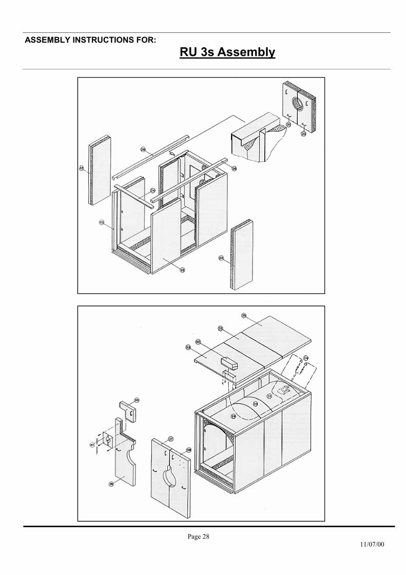
Follow the number order for jacket assembly completion
ASSEMBLY INSTRUCTIONS FOR: RU 3s Assembly
ASSEMBLY INSTRUCTIONS FOR:
Page 28 11/07/00
ASSEMBLY INSTRUCTIONS FOR: RU 3S
ASSEMBLY INSTRUCTIONS FOR: RU 3s Assembly

ASSEMBLY INSTRUCTIONS FOR:
Page 29 11/07/00

ASSEMBLY INSTRUCTIONS FOR:
Page 30 11/07/00
ASSEMBLY INSTRUCTIONS FOR: RU BOILERS
E. & O.E
STREBEL LTD 1F Albany Park Industrial Estate Frimley Road, Camberley, Surrey, GU16 7PB Telephone: 01276 685422 Fax: 01276 685405 E-mail address: [email protected] Website: www.strebel.co.uk
THE COMPANY RESERVES THE RIGHT TO CHANGE SPECIFICATIONS AND DIMENSIONS WITHOUT NOTICE